1
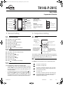
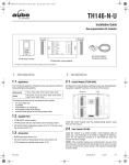
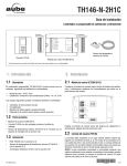
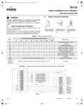
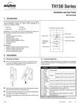
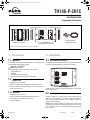
400-280-014-A (TH146-P-2H1C) ENG.fm Page 1 Wednesday, May 23, 2007 4:12 PM
TH146-P-2H1C
Installation Guide
Programmable 2H1C Controller
Removable
Connector *
Removable
Connector *
AC144-03 Outdoor
Temperature Sensor
TH146-P User Console
CT280-2H1C Control Module
* To remove a connector from the control module, pry with a screwdriver.
1. Introduction
2. Installation
1.1
2.1
Applications
The TH146-P-2H1C programmable controller can be used with any
of the following heating/cooling systems:
Control Module (CT280-2H1C)
Configure the control module according to your type of heating/cooling system using DIP switches on the back of the module.
Heat pump - 1H1C, 2H1C
HVAC - 1H, 1C, 1H1C
The following devices can be connected to the controller:
air recirculation fan
humidifier
dual-register meter (dual energy)
remote control device (for the unoccupied mode)
1.2
Supplied Parts
• CT280-2H1C control module
• TH146-P console with two wall anchors and mounting screws
• AC144-03 outdoor temperature sensor (3 m or 10 ft) with mounting clip (see section 2.6)
1.3
Accessories
• RC845 relay (see section 2.4)
• AC146-410 plenum temperature sensor (see section 2.7)
• CT241 telephone controller (see section 2.9)
• AC130-12 wall plate
Install the control module near the heating/cooling system, away
from any heat source.
2.2
User Console (TH146-P)
Install the console in a central location. Avoid locations with air
drafts (e.g., top of staircase or air outlet) or stagnant air (behind a
door). Do not install the console on a wall hiding air ducts nor
expose it to direct sunlight.
NOTE: If this controller replaces an old thermostat, any two of the
wires that were connected to the thermostat can be used to connect
the user console to the control module. The maximum wiring length
is 30 m (100 ft).
TH146-P-2H1C
400-280-014-A
5/23/07
1/11
400-280-014-A (TH146-P-2H1C) ENG.fm Page 2 Wednesday, May 23, 2007 4:12 PM
n
Choose a location about 1.5 m (5 ft) above the floor on an
inside wall.
o
p
q
r
Loosen the captive screw under the console.
Detach the console from its base by pulling the bottom section.
Secure the base using the wall anchors and screws.
Connect the console to controller terminals TH and TH (no
polarity).
2.3
Heating/Cooling System
The terminals used to connect the heating/cooling system depend
on the type of system. See the appropriate wiring table on page 4.
2.4
RC845 Relay
If you have an add-on installation, you might need an RC845 relay
to connect the furnace (auxiliary heating) and its fan to the controller. Install the relay near the control module and connect the wires
as follows:
Install the sensor on the side of the plenum and
position it such that its aperture faces the air
flow.
Connect the sensor to controller terminals PS
and CS (no polarity). For more information,
refer to the instructions provided with the sensor.
NOTE: The maximum wiring length is 30 m
(100 ft).
2.8
Dual-energy Input
NOTE: The dual-energy input can be used only with a heat pump
equipped with auxiliary heat.
The dual-energy input can be connected to the dual-register meter
equipped with a normally open (NO) dry contact. Connect the controller terminals DE and CC to the meter terminals (yellow and red
wires).
• relay terminals W, G and C to controller terminals W, G and C.
The contact closes when the outdoor temperature drops below the
temperature setting on the meter. When the contact is closed, the
heat pump is disabled and only the auxiliary heat can be used.
• relay terminals T and T to the appropriate furnace terminals: T
and T (oil); TH and TH (gas); R and W (electric).
2.9
NOTE: Refer to the relay’s installation instructions for more details.
2.5
Humidifier
Connect the humidifier in series with the power supply between
controller terminals H and H (dry contact).
2.6
Outdoor Sensor (AC144-03)
The outdoor sensor is required for the following:
• outdoor temperature display
• balance points (heat pumps only, see section 4.2)
• defrost point (heat pumps only, see section 4.3)
• automatic humidity control (see section 7.2)
When installing the sensor, observe the following guidelines:
• Avoid locations where the sensor can be covered with snow or
exposed to direct sunlight.
To use the unoccupied mode, the controller requires a remote control device such as Aube’s CT241 telephone controller equipped
with a normally open (NO) dry contact placed between terminals UN
and CC of the controller. The unoccupied mode is activated when
the contact closes. (See section 6.4.)
3. Configuration
3.1
NOTE: The maximum wiring length is 30 m (100 ft).
Configuration Switches
To access the configuration switches, loosen the captive screw
under the console and separate the console from its base by pulling
the bottom section.
3.1.1
Access Mode (SW1-1)
INST: Installer mode. Gives access to all configuration parameters.
NOTE: In installer mode, the short-cycle protection is disabled
and the interstage delay is reduced to 1 minute.
• Avoid air outlets and concealed chimneys or stove pipes.
Install the sensor using its mounting clip and connect it to controller
terminals OS and CS (no polarity).
Unoccupied Mode Input
USER: User mode. Gives access to configuration parameters 1 to 4
only.
3.1.2
Keypad Lock (SW1-2)
I: The keypad is locked. Settings cannot be changed.
2.7
Plenum Sensor (AC146-410)
The plenum sensor is required for the following:
• low temperature limit inside the plenum (HVAC only)
• high temperature limit inside the plenum (HVAC only)
• fan limit if gas heating is used (HVAC only)
• high pressure protection during defrost cycle (This protection is
generally needed for add-on installations only. It is not needed if
the heat pump is not connected to the controller terminal WW.)
TH146-P-2H1C
O: The keypad is unlocked.
3.2
n
o
p
q
r
s
Software Configuration
Place the console in Installer mode (INST) using the SW1-1
switch on the back of the console.
Press the Mode button for 3 seconds to access the configuration menu (see page 8). The first menu item (parameter) is displayed.
To view another menu item, briefly press the Mode button.
To modify a parameter, press either
button.
To exit the configuration menu, press
.
Return the console to User mode (USER).
400-280-014-A
5/23/07
2/11
400-280-014-A (TH146-P-2H1C) ENG.fm Page 3 Wednesday, May 23, 2007 4:12 PM
4. Principles of Operation
4.1
Automatic Heating/Cooling Changeover
4.4
The controller can be configured for either of the following types of
heat pump installations (see page 8, item 8).
•
With automatic heating/cooling mode changeover, there’s no need
to adjust the controller at every change of season or weather condition. The controller switches automatically between heating mode
and cooling mode to maintain the desired temperature.
Manual Mode
When the controller is in manual mode, the heating/cooling mode
changeover occurs as follows:
The controller switches to cooling mode when the indoor temperature is higher than the setpoint by more than 1.5°C (2.5°F)
for 15 minutes.
•
The controller switches the heating mode when the indoor temperature is lower than the setpoint by more than 1.5°C (2.5°F)
for 15 minutes.
Automatic Mode
•
•
When the controller is in automatic mode, it follows the programmed
schedule. Two temperature settings (heating setpoint and cooling
setpoint) are programmed for each period of the schedule. The
heating/cooling mode changeover occurs as follows:
•
•
When the controller is in heating mode, the indoor temperature
is maintained at the heating setpoint. However, if the temperature rises and remains above the cooling setpoint for 15 minutes, the controller will switch to cooling mode.
When the controller is in cooling mode, the indoor temperature
is maintained at the cooling setpoint. However, if the temperature drops and remains below the heating setpoint for 15 minutes, the controller will switch to heating mode.
4.2
Balance Points (heat pumps only)
Balance Points are used to disable the heat pump or the auxiliary
heating when the outdoor temperature is below or above a set temperature.
•
When the outdoor temperature is below the Balance Point Low
(bP L), the heat pump is disabled and only auxiliary heating can
be used (see page 8, item 5).
•
When the outdoor temperature is above the Balance Point High
(bP H), the auxiliary heat is disabled and only the heat pump
can be used (see page 8, item 6).
NOTE: Balance Points cannot be used if the AC144-03 outdoor
temperature sensor is not connected to the controller.
4.3
Heating During Defrost (heat pumps only)
The auxiliary heat is activated during defrost except under the following conditions:
•
When the outdoor temperature is above the defrost point (see
page 8, item 7). Note: This condition will not apply if the
AC144-03 outdoor sensor is not connected to the controller.
•
When the plenum temperature is above 40°C (104°F). The
auxiliary heat is re-activated when the plenum temperature
drops below 32°C (90°F). Note: This condition will not apply if
the AC146-410 plenum sensor is not connected to the controller.
NOTE: The auxiliary heat’s short-cycle protection is disabled during
defrost.
TH146-P-2H1C
Types of Heat Pump Installations
Add-on Installation: This type of installation is performed
when adding a heat pump to an existing furnace. When the
heat pump is installed, the furnace becomes the auxiliary heat
source. In this type of installation, the indoor coils are usually
installed downstream of the auxiliary heat source. When the
controller is configured for an add-on installation, the heat
pump is disabled during auxiliary heating to prevent overpressure.
New Installation: In this type of installation, as there is not
already a furnace, the auxiliary heat source is installed at the
same time as the heat pump. In this type of installation, the
indoor coils are located upstream of the auxiliary heat. When
the controller is configured for a new installation, the heat pump
and the auxiliary heat can operate simultaneously.
4.5
Interstage Delay
Interstage Delay is the time allocated for the temperature to return
to an acceptable value when it deviates too far from the setpoint. If
this time has elapsed, the next heating or cooling stage is activated.
The heating or cooling stage will be deactivated when the temperature returns to an acceptable value. The Interstage Delay is fixed at
4 minutes if the controller is configured for an HVAC system and is
user-adjustable if it is configured for a heat pump (see page 8,
item 9).
4.6
Low and High Temperature Limits
Low Temperature Limit (LLMT) and High Temperature Limit (HLMT)
are used to keep the plenum from becoming too cold or too hot.
During cooling, if the plenum temperature is lower than LLMT, a
cooling stage is deactivated starting with the one that was last activated. If, after a while, the temperature is still too low, another cooling stage is deactivated and so on. Likewise, during heating, if the
plenum temperature is higher than HLMT, a heating stage is deactivated starting with the one that was last activated. If, after a while,
the temperature is still too high, another heating stage is deactivated and so on. (see page 8, items 10 and 11.)
WARNING: LLMT and HLMT can be used in parallel with an
UL353-approved device but they do not replace such device.
NOTE: LLMT and HLMT cannot be used if the plenum temperature
sensor is not connected to the controller.
4.7
Smart Fan
When Smart Fan is enabled (see page 8, item 15), the fan operates
as follows:
•
During periods 2 and 4 of automatic mode and during the unoccupied mode (i.e., when you are away from home or sleeping),
the fan operates only when heating or cooling is activated.
•
The fan operates continuously the rest of the time.
NOTE: For Smart Fan to work, set the fan to On (see section 5.3).
400-280-014-A
5/23/07
3/11
400-280-014-A (TH146-P-2H1C) ENG.fm Page 4 Wednesday, May 23, 2007 4:12 PM
Wiring Tables
Heat Pump
Terminal
TH
TH
PS
Device
Console
Plenum sensor
CS
Common S
OS
Outdoor sensor
1H1C
2H1C
Connect the console between the TH terminals (no polarity)
Connect the plenum sensor between the PS and CS terminals (no polarity)
Common terminal for the plenum sensor and the outdoor sensor
Connect the outdoor sensor between the CS and OS terminals (no polarity)
DE
Dual Energy
Connect the dual-register meter between the DE and CC terminals (no polarity)
CC
Common C
Common terminal for the dual-energy meter and the unoccupied mode input
UN
Unoccupied mode input
Connect a dry contact between the UN and CC terminals (no polarity)
Humidifier (24 Vac / 1 A)
Connect the humidifier between the H terminals (dry contact)
H
H
R
C
Y
Power (24 Vac)
Compressor (24 Vac / 1 A)
√
√
√
√
√
√
√
W
Auxiliary heat (24 Vac / 1 A)
O/B
Reversing valve (24 Vac / 1 A)
√
√
G
Fan (24 Vac / 1A)
√
√
L
Fault (24 Vac / 5 mA)
√
√
WW
Defrost (24 Vac / 5 mA)
√
√
HVAC
Terminal
TH
TH
Device
Console
PS
Plenum sensor
CS
Common S
OS
Outdoor sensor
1H
1C
1H1C
Connect the console sensor between the TH terminals (no polarity)
Connect the plenum sensor between the PS and CS terminals (no polarity)
Common terminal for both plenum sensor and outdoor sensor
Connect the outdoor sensor between the OS and CS terminals (no polarity)
DE
Not used
CC
Common C
UN
Unoccupied mode input
Connect a dry contact between UN and R terminals (no polarity)
Humidifier (24 Vac / 1 A)
Connect the humidifier between the H terminals (dry contact)
H
H
R
C
Power (24 Vac)
Common terminal for the unoccupied mode input
√
√
√
√
√
√
√
Y
Cooling unit (24 Vac / 1 A)
W
Heating unit (24 Vac / 1 A)
√
Fan (24 Vac / 1 A)
√
O/B
G
Not used
√
L
Not used
WW
Not used
TH146-P-2H1C
√
√
√
400-280-014-A
5/23/07
4/11
400-280-014-A (TH146-P-2H1C) ENG.fm Page 5 Wednesday, May 23, 2007 4:12 PM
Wiring Diagram: 2H1C Heat Pump — New Installation
AC146-410
Compressor
AC144-03
Auxiliary Heat
Dual Energy
Reversing Valve
CT241
Fan
Humidifier
Fault
Defrost
TH146-P-2H1C
400-280-014-A
5/23/07
5/11
400-280-014-A (TH146-P-2H1C) ENG.fm Page 6 Wednesday, May 23, 2007 4:12 PM
Wiring Diagram: 2H1C Heat Pump — Add-on Installation
AC146-410
AC144-03
Compressor
Reversing Valve
Dual Energy
Fault
CT241
Defrost
Humidifier
Fan Limit
Furnace
TH146-P-2H1C
400-280-014-A
5/23/07
6/11
400-280-014-A (TH146-P-2H1C) ENG.fm Page 7 Wednesday, May 23, 2007 4:12 PM
Wiring Diagram: 1H1C HVAC
AC146-410
AC144-03
Cooling Unit
Heating Unit
Fan
CT241
Humidifier
TH146-P-2H1C
400-280-014-A
5/23/07
7/11
400-280-014-A (TH146-P-2H1C) ENG.fm Page 8 Wednesday, May 23, 2007 4:12 PM
Configuration Menu
Item
HP
HVAC
Parameters
1
√
√
Time format
2
3
√
√
√
√
√
Early Start
Display
Options
Default
12 Hr / 24
Hr
24 Hr
On / OF
OF
Automatic daylight
savings adjustment
OF / 1 / 2
Temperature format
°C / °F
°C
Description
Select the time display format.
•
On: Heating or cooling starts in advance (as determined by the controller) so that the desired temperature is attained at the set times.
•
OF (Off): Heating or cooling starts at the set times.
NOTE: Early Start applies for periods 1 and 3 (P1 and P3) only. When
this feature is enabled, heating or cooling will start in advance of the set
time for P1 and P3 but will start at the set time for P2 and P4.
•
OF (Off): The function is deactivated.
•
1 : The controller switches to daylight savings time on the first Sunday
of April and to normal time on the last Sunday of October.
•
2 : The controller switches to daylight savings time on the second
Sunday of March and to normal time on the first Sunday of November.
OF
4
√
5
√
Balance point low
-30 to 10°C
(-22 to 50°F)
-10°C
(14°F)
Set the bP L limit (see section 4.2).
NOTE: Lower bP L below its minimum (- -) if you do not wish to use this
function.
6
√
Balance point high
-5 to 30°C
(23 to 86°F)
5°C
(41°F)
Set the bP H limit (see section 4.2).
NOTE: Raise bP H above its maximum (- -) if you do not wish to use this
function.
7
√
Defrost point
-10 to 15°C
(14 to 59°F)
10°C
(50°F)
Set the defrost point temperature (see section 4.3).
NOTE: Raise the defrost point above its maximum (- -) if you do not wish
to use this function.
Select the temperature display format.
Set according to the type of heat pump installation (see section 4.4).
8
9
√
Installation type
√
Ad / nr
•
Ad (add-on): Use this setting when the indoor coils are located downstream of the auxiliary heat source. This is generally the case for addon installations.
•
nr (normal): Select this setting when the indoor coils are located
upstream of the auxiliary heat source. This is generally the case for
new installations.
Ad
Auxiliary
interstage delay
5 to 90 min.
30 min.
Set the interstage delay for the auxiliary stage (see section 4.5).
10
√
Low temperature
limit
-10 to 20°C
(14 to 68°F)
5°C
(41°F)
Set the low temperature limit of the plenum (see section 4.6).
NOTE: This function is not used if you lower LLMT below its minimum
(- -) or if the plenum sensor is not connected to the controller.
11
√
High temperature
limit
30 to 90°C
(86 to
194°F)
70°C
(158°F)
Set the high temperature limit of the plenum (see section 4.6).
NOTE: This function is not used if you raise HLMT above its maximum (-) or if the plenum temperature sensor is not connected to the controller.
√
Cycles per hour
2 to 6
4
Select the number of heating/cooling cycles per hour. For optimal heating
control, use the setting that matches your system as follows: 3=20 min
(hot water, 90%+ high-efficiency furnace), 4=15 min (gas or oil), 5=12 min
(gas or oil), 6=10 min (electric).
12
√
This setting determines the fan operation in automatic mode when the
system is in heating mode.
√
13
14
Heat type
GA / EL
EL
√
Fan limit
38 to 90°C
(100 to
194°F)
80°C
(176°F)
15
√
√
Smart Fan
On / OF
OF
16
√
√
Temperature
setback
0 to 9°C
(0 to 16°F)
0°C
(0°F)
17
√
√
Humidifier
operating mode
Co / HE / Fn
Fn
•
EL (electric heating): The fan starts and stops at the same time as
heating.
•
GA (gas or oil heating): The fan starts when the temperature inside
the plenum rises above the Fan Limit (see item 14) and stops when
the temperature drops 12°C below the Fan Limit. Note: The fan will
not start if the plenum temperature sensor is not connected to the controller.
This parameter is available only when gas heating is selected (see item 13).
WARNING: FLMT can be used in parallel with an UL353-approved
device but they do not replace such device.
NOTE: The fan will not start if you raise FLMT above its maximum (--).
On: Smart Fan is On (see section 4.7).
OF: Smart Fan is Off.
Set the amount of temperature setback when the controller is placed in
Unoccupied mode (see section 6.4).
•
Co (conventional): The humidifier will operate if the humidity is too
low. If the fan is not already On, it will turn On at the same time as the
humidifier.
•
HE (heat): The humidifier can operate only when heating is activated.
•
Fn (fan): The humidifier can operate as long as the fan is running,
whether heating is activated or not.
NOTE: The humidifier is disabled when cooling is activated.
Note: Only items 1 to 4 are available when the controller is placed in user mode (SW1-1 switch).
TH146-P-2H1C
400-280-014-A
5/23/07
8/11
400-280-014-A (TH146-P-2H1C) ENG.fm Page 9 Wednesday, May 23, 2007 4:12 PM
TH146-P-2H1C
User’s Guide
Programmable H/C Controller
Indicator LEDs
Time and day setting
Programming
Temperature
adjustment
mode selection
Program day selection
Fan operating
mode selection
Program clear
System operating
mode selection
Humidity setting
Up/Down buttons
Return
Indicator LEDs
Day
FAULT: System fault
EH: Emergency heat mode
DE: Dual energy
Clock
Backlight
Indoor temperature
The screen is lit for 12 seconds
when any button is pressed.
However, the screen remains lit
while you are configuring the
controller.
Indoor humidity
Outdoor temperature
5. General Setting
6. Temperature Setting
5.1
6.1
n
o
p
q
r
s
t
Press Clk. The hour display flashes.
Set the hour using
.
Set the minutes using
Appears when the
temperature setpoint
is displayed
Indoor temperature
Set the day using
Press
Heating is On
.
Press Clk. The day display flashes.
Cooling is On
System operating mode
Auxiliary heating is On
.
to return to the normal display.
Date Setting
Temperature adjustment
mode (appears when the
system is in automatic
mode, disappears when it
is in manual mode)
Fan operating mode (appears when the fan is in
continuous mode, disappears when it is in automatic mode)
Press Clk for 3 seconds to display the year.
Set the year using
.
Press Clk to display the month.
Set the month using
.
Press Clk to display the date.
Set the date using
Press
5.3
.
to return to the normal display.
Fan Operating Mode
Press the Fan button to select the fan operating mode.
•
In automatic mode, the fan runs only when heating or cooling is
activated. NOTE: For gas-operated HVAC systems, there might
be a delay before the fan starts or stops when heating is activated or deactivated.
•
Display
Press Clk. The minute display flashes.
5.2
n
o
p
q
r
s
t
Clock and Day Setting
In continuous mode, the fan runs continuously and the
symbol is displayed. NOTE: if Smart Fan is enabled, when the controller is in periods 2 and 4 of automatic mode and in
unoccupied mode, the fan will run only when heating or cooling
is activated. The fan will run continuously the rest of the time
TH146-P-2H1C
The controller normally displays the measured indoor temperature.
To view the setpoint, press one of the
buttons. The setpoint and
the symbol will be displayed for the next 5 seconds.
6.2
System Operating Mode
Press Mode to place the system in one of the following modes:
HEAT
The system is in heating mode.
COOL
The system is in cooling mode.
AUTO
The system is in automatic changeover mode. (The system
switches between heating mode and cooling mode to maintain the desired temperature.)
OFF
The system is off.
EHEAT
The system is in emergency heat mode. Only auxiliary heating is used when there is a call for heat. (This mode applies
only when the controller is connected to a heat pump
equipped with auxiliary heating).
400-280-014-A
5/23/07
9/11
400-280-014-A (TH146-P-2H1C) ENG.fm Page 10 Wednesday, May 23, 2007 4:12 PM
6.3
Temperature Adjustment
6.3.1 Manual Adjustment
Use this mode to set the temperature manually. To place the controller in this mode, press Auto/Man so that disappears from the
screen. Set the temperature using the
buttons.
NOTE: If the controller is in automatic heat/cool changeover (see
section 6.2), the setpoint is automatically reduced or raised by 1°C
(1.8°F) when the controller switches to heating mode or to cooling
mode respectively. For example, if the setpoint is 24°C (75°F) in
heating mode, it will become 25°C (77°F) in cooling mode and will
return to 24°C (75°F) when the controller switches back to heating
mode.
6.3.2 Automatic Adjustment
Use this mode if you want the controller to adjust the temperature
according to the programmed schedule. To place the controller in
this mode, press Auto/Man so that appears on the screen.
point is 22°C (72°F) and you set the heating setpoint to 23°C (73°F),
the cooling setpoint will automatically become 24°C (75°F). However, if you raise the heating setpoint to 21°C (70°F), the cooling
setpoint will remain at 22°C (72°F). The same principle applies
when you set the cooling temperature.
•
Press
to exit.
The following diagram shows how to navigate the programming
menu.
MO
TU
6:00
6:00
Day
Pgm
P1
Heat
21
Mode
Cool
Pgm
Heat
25.5
21
Mode
Cool
25.5
Pre-programmed Schedule
Pgm
Pgm
The following schedule has been programmed at the factory. Two
temperature settings are programmed for each period of the schedule: a heating setpoint and a cooling setpoint.
8:00
Pre-programmed Schedule
P1
Heating
21°C (70°F)
Cooling
25.5°C (78°F)
P2
Heating
16.5°C (62°F)
Cooling
29.5°C (85°F)
P3
Heating
21°C (70°F)
Cooling
25.5°C (78°F)
P4
Heating
16.5°C (62°F)
Cooling
28°C (82°F)
MO TU WE TH FR SA SU
Heat
16.5
8:00 a.m.
--
6:00 p.m.
--
10:00 p.m.
Modifying the Schedule
You can program up to 4 periods per day. To program a period, you
need to set the start time, the heating setpoint and the cooling setpoint. The program can be different for each day of the week.
•
Press Pgm to enter the programming mode. The settings for
Monday, Period 1 (P1) appear.
•
To select a day to program, press Day until the day is displayed. Press for 3 seconds to select all 7 days.
NOTE: If you select all 7 days, the settings of the displayed
period will be copied to all 7 days. For example, if you select all
7 days while period 1 is displayed, they will all now have the
same settings for period 1. If you display period 2 while all 7
days are selected, they will all now have the same settings for
period 2.
•
Pgm
P2
6:00 a.m.
8:00
Mode
Day
Cool
29.5
Pgm
Heat
16.5
Mode
Cool
29.5
Temporary Bypass
When you modify the temperature setpoint while the controller is in
automatic mode, the new temperature is used for the next 2 hours.
The icon flashes during the bypass. After the bypass, the temperature set for the current period is used.
6.4
Unoccupied Mode
You can place the controller in the unoccupied mode using a remote
control device such as Aube’s CT241 telephone controller. In this
mode, the temperature is lowered in heating mode or raised in cooling mode (see page 8, item 16). The message UNOC appears during
the unoccupied mode.
NOTE: Automatic changeover is disabled during the unoccupied
mode.
Temporary Bypass
In the unoccupied mode, only the
buttons work. When you
adjust the temperature during this mode, the new temperature will
be used for the next 2 hours, after which the controller will return to
the previous setpoint. The message UNOC flashes during the bypass.
To set the start time of a period, press Pgm until the period
number (P1 to P4) is displayed and the time display flashes.
Then press the
buttons. The time changes in increments of
15 minutes.
NOTE: To skip a period, display the period and press Clr. For
example, in the pre-programmed schedule, periods 2 and 3
have been skipped for Saturday and Sunday.
•
To set the temperatures for a period, press Pgm until the period
number (P1 to P4) is displayed and the temperature display
flashes. If necessary, press Mode to display the heating setpoint or the cooling setpoint. Press the
buttons to set the
temperature.
NOTE: The cooling setpoint is always higher than the heating setpoint by a minimum of 1°C (1.8°F). For example, if the cooling setTH146-P-2H1C
400-280-014-A
5/23/07
10/11
400-280-014-A (TH146-P-2H1C) ENG.fm Page 11 Wednesday, May 23, 2007 4:12 PM
7. Humidity Setting
7.1
TH146-P USER CONSOLE
Temperature setpoint range
Heating mode: 5°C to 30°C (40°F to 86°F)
Display
Cooling mode: 15°C to 40°C (59°F to 104°F)
Humidity setpoint range: 5 to 60%
Indoor temperature display range: 0°C to 70°C (32°F to 158°F)
Outdoor temp. display range: -50°C to 70°C (-58°F to 158°F)
Temperature display resolution: 0.5°C (1°F)
Program protection: non-volatile memory
Operating temperature: 0°C to 50°C (32°F to 122°F)
Storage temperature: -20°C to 50°C (-4°F to 122°F)
Appears when the
humidity setpoint
is displayed
Humidity conditions: 0 to 95%, non-condensing
Humidifier is On
Humidity control mode
(auto, manual or off)
Humidity level
7.2
Humidity Adjustment
Manual Adjustment
The humidity level is set by the user (5 to 60%).
n
o
p
Press the Hum button until MAN appears on the screen.
n
Press the Hum button until AUTO appears on the screen. The
humidity level set by the controller is also displayed.
o
p
Press one of the
Press one of the
buttons to adjust the humidity level.
Press the
button.
Automatic Adjustment
The humidity level is set by the controller based on the outdoor temperature to prevent ice formation or condensation on the windows
while providing enough humidity for your comfort. However, the user
can apply an offset (-9 to 9%). For example, the user can enter a
negative offset if there is ice formation or condensation on the windows.
Press the
buttons to enter or change the offset.
button.
Off
To turn off the humidity control:
n
o
Press the Hum button until OFF appears on the screen.
Press the
button to save and exit the programming.
8. Technical Specifications
Dimensions: 79 x 79 x 24 mm (3.1 x 3.1 x 1 in.)
9. Warranty
Aube warrants this product, excluding battery, to be free from defects in the
workmanship or materials, under normal use and service, for a period of three (3)
years from the date of purchase by the consumer. If at any time during the
warranty period the product is determined to be defective or malfunctions, Aube
shall repair or replace it (at Aube's option).
If the product is defective,
(i) return it, with a bill of sale or other dated proof of purchase, to the place from
which you purchased it, or
(ii) contact Aube. Aube will make the determination whether the product should
be returned, or whether a replacement product can be sent to you.
This warranty does not cover removal or reinstallation costs. This warranty shall
not apply if it is shown by Aube that the defect or malfunction was caused by
damage which occurred while the product was in the possession of a consumer.
Aube's sole responsibility shall be to repair or replace the product within the terms
stated above. AUBE SHALL NOT BE LIABLE FOR ANY LOSS OR DAMAGE OF
ANY KIND, INCLUDING ANY INCIDENTAL OR CONSEQUENTIAL DAMAGES
RESULTING, DIRECTLY OR INDIRECTLY, FROM ANY BREACH OF ANY
WARRANTY, EXPRESS OR IMPLIED, OR ANY OTHER FAILURE OF THIS
PRODUCT. Some provinces and states do not allow the exclusion or limitation of
incidental or consequential damages, so this limitation may not apply to you.
THIS WARRANTY IS THE ONLY EXPRESS WARRANTY AUBE MAKES ON
THIS PRODUCT. THE DURATION OF ANY IMPLIED WARRANTIES,
INCLUDING THE WARRANTIES OF MERCHANTABILITY AND FITNESS FOR
A PARTICULAR PURPOSE, IS HEREBY LIMITED TO THE THREE-YEAR
DURATION OF THIS WARRANTY. Some provinces and states do not allow
limitations on how long an implied warranty lasts, so the above limitation may not
apply to you.
This warranty gives you specific legal rights, and you may have other rights which
vary by province or state.
10.Support
If you have any questions about the product installation or
operation, or concerning the warranty, contact us at the address
shown below.
CT280-2H1C CONTROL MODULE
Power supply: 24 VAC
Current consumption: 150 mA
Maximum load per output: 1 A @ 24 VAC
Short cycle protection: 2 minutes
Control cycles: 2 to 6 per hour
Operating temperature: 0°C to 50°C (32°F to 122°F)
Storage temperature: -20°C to 50°C (-4°F to 122°F)
Humidity conditions: 0 to 95%, non-condensing
Dimensions: 95 x 137 x 30 (3.8 x 5.4 x 1.2 in.)
TH146-P-2H1C
705 Montrichard
Saint-Jean-sur-Richelieu, Quebec
J2X 5K8
Canada
Tel: (450) 358-4600
Toll-free: 1-800-831-AUBE
Fax: (450) 358-4650
Email: [email protected]
10, rue Ampère
95500 Gonesse
France
Tel: 33 (0) 1 34 07 99 00
Fax: 33 (0) 1 34 07 99 19
Email: [email protected]
For more information on our products, visit us at:
www.aubetech.com
®
As an ENERGY STAR partner, Aube Technologies
has determined that this product meets the
ENERGY STAR guidelines for energy efficiency.
400-280-014-A
5/23/07
11/11