1
TM-L90/TM-L90 Peeler
Technical Reference
Guide
EPSON
English
410019401
TM-L90/TM-L90 with Peeler Technical Reference Guide
Cautions
❏
No part of this document may be reproduced, stored in a retrieval system, or transmitted in any form or by any
means, electronic, mechanical, photocopying, recording, or otherwise, without the prior written permission of
Seiko Epson Corporation.
❏
The contents of this document are subject to change without notice. Please contact us for the latest information.
❏
While every precaution has been taken in the preparation of this document, Seiko Epson Corporation assumes no
responsibility for errors or omissions.
❏
Neither is any liability assumed for damages resulting from the use of the information contained herein.
❏
Neither Seiko Epson Corporation nor its affiliates shall be liable to the purchaser of this product or third parties
for damages, losses, costs, or expenses incurred by the purchaser or third parties as a result of: accident, misuse, or
abuse of this product or unauthorized modifications, repairs, or alterations to this product, or (excluding the U.S.)
failure to strictly comply with Seiko Epson Corporation’s operating and maintenance instructions.
❏
Seiko Epson Corporation shall not be liable against any damages or problems arising from the use of any options
or any consumable products other than those designated as Original EPSON Products or EPSON Approved
Products by Seiko Epson Corporation.
Trademarks
EPSON®
and
ESC/POS®
are registered trademarks of Seiko Epson Corporation
ESC/POS® Command System
EPSON has been taking industryinitiatives with its own POS printer command system (ESC/POS). ESC/POS has a
large number of commands, including patented ones. Its high scalability enables users to build versatile POS systems.
The system is compatible with all types of EPSON POS printers and displays. Moreover, its flexibility makes it easy to
upgrade in the future. The functionality and the user-friendliness are valued around the world.
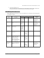
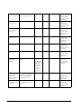
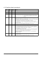
Revision Table
Rev. B
Rev
Page
Description
Rev. A
all pages
Newly authorized
Rev. B
all pages
Descriptions of horizontal installation deleted
i
For Safety
Key to Symbols
The symbols in this manual are identified by their level of importance, as defined below. Read
the following carefully before handling the product.
WARNING:
You must follow warnings carefully to avoid serious bodily injury.
CAUTION:
Provides information that must be observed to prevent damage to the equipment or
loss of data.
❏ Possibility of sustaining physical injuries.
❏ Possibility of causing physical damage.
❏ Possibility of causing information loss.
Note:
Provides important information and useful tips on handling the equipment.
ii
Rev. B
TM-L90/TM-L90 with Peeler Technical Reference Guide
Warnings
WARNING:
❏ Shut down your equipment immediately if it produces smoke, a strange odor, or
unusual noise. Continued use may lead to fire or electric shock. Immediately unplug
the equipment.
❏ Only disassemble this product as described in this manual. Do not make
modifications to the unit. Tampering with this product may result in injury, fire, or
electric shock.
❏ Do not install this product or handle cables during a thunderstorm in order to avoid
risk of electric shock.
❏ Be sure to use the specified power source. Connection to an improper power source
may cause fire or shock.
❏ Never insert or disconnect the power plug with wet hands. Doing so may result in
severe shock.
❏ Do not allow foreign matter to fall into the equipment. Penetration by foreign
objects may lead to fire or electric shock.
❏ If water or other liquid spills into this equipment, turn off the power supply switch and
unplug the power cord immediately. Continued usage may lead to fire or electric
shock.
❏ Do not place multiple loads on power outlet. Overloading the outlet may lead to
fire. Always supply power directly from a standard domestic power outlet.
❏ Handle the power cord with care. Improper handling may lead to fire or electric
shock.
Rev. B
•
Do not modify or attempt to repair the cord.
•
Do not place any heavy object on top of the cord.
•
Avoid excessive bending, twisting, and pulling.
•
Do not place the cord near heating equipment.
•
Check that the plug is clean before plugging it in.
•
Be sure to push the plug all the way in.
iii
Cautions
CAUTION:
❏ Do not connect cables in ways other than those mentioned in this manual. Different
connections may cause equipment damage and burning.
❏ Be sure to set this equipment on a firm, stable horizontal surface. Product may break
or cause injury if it falls.
❏ Do not use in locations subject to high humidity or dust levels. Excessive humidity and
dust may cause equipment damage, fire, or shock.
❏ Do not place heavy objects on top of this equipment. Never stand or lean on this
equipment. Equipment may fall or collapse, causing breakage and possible injury.
❏ To ensure safety, unplug this equipment prior to leaving it unused for an extended
period.
❏ Parts on the circuit board may become hot during operation. Therefore, wait
approximately 10 minutes after turning the power off before touching them.
❏ To avoid injury, take care not to insert fingers or any part of the hand in the roll paper
opening where the manual cutter is installed.
❏ Do not open the roll paper cover without taking the necessary precautions, as this
can result in injury from the autocutter fixed blade.
❏ Be sure to replace the batteries correctly. Improper replacement may cause a
battery burst. Only use batteries provided by EPSON. Follow the requirements of your
regional to properly dispose of used batteries.
Modular Connector
Use the modular connectors specifically designed for the cash drawer for this product. Do not
connect these connectors to an ordinary telephone line.
iv
Rev. B
TM-L90/TM-L90 with Peeler Technical Reference Guide
About This Manual
Aim of the Manual
This manual was created to provide all information necessary for system planning, design,
installations and application of the printer for designers and developers of POS systems.
Manual Content
The manual is made up of the following sections:
Chapter 1
Product Overview
Chapter 2
Setup
Chapter 3
Connecting the Host Computer and Options
Chapter 4
Application Development Information
Chapter 5
ESC/POS Command Related Information
Chapter 6
Product Specifications
Appendix A
Interfaces and Connectors
Appendix B
Consumable Supplies Specifications
Appendix C
Character Code Table
Appendix D
Option Specifications
Appendix E
Maintenance
Appendix F
Troubleshooting
Appendix G
Shipping Procedures
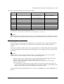
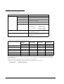
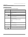
Related Documentation
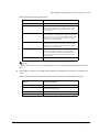
The following documents also relate to the TM-L90 / TM-L90 peeler specification.
Rev. B
Name of document
Description
TM-L90 User’s Manual
Comes with the printer.
Provides information to enable POS operators to use the
TM-L90 safely and correctly.
TM-L90 with Peeler User’s Manual
Comes with the printer.
Provides information to enable POS operators to use the
TM-L90 peeler specification safely and correctly.
ESC/POS Application Programming Guide
Provides detailed ESC/POS command information.
Contact us to obtain this guide.
v
vi
Rev. B
TM-L90/TM-L90 with Peeler Technical Reference Guide
Contents
Revision Table . . . . . . . . . . . . . . . . . . . . . . . . . . . . . . . . . . . . . . . . . . . . . . . . . . . . . . . . . . . . . . . . . . . . . . . . . . .
For Safety . . . . . . . . . . . . . . . . . . . . . . . . . . . . . . . . . . . . . . . . . . . . . . . . . . . . . . . . . . . . . . . . . . . . . . . . . . . . . .
Key to Symbols . . . . . . . . . . . . . . . . . . . . . . . . . . . . . . . . . . . . . . . . . . . . . . . . . . . . . . . . . . . . . . . . . . . . . .
Warnings . . . . . . . . . . . . . . . . . . . . . . . . . . . . . . . . . . . . . . . . . . . . . . . . . . . . . . . . . . . . . . . . . . . . . . . . . . .
Cautions . . . . . . . . . . . . . . . . . . . . . . . . . . . . . . . . . . . . . . . . . . . . . . . . . . . . . . . . . . . . . . . . . . . . . . . . . . . .
Modular Connector . . . . . . . . . . . . . . . . . . . . . . . . . . . . . . . . . . . . . . . . . . . . . . . . . . . . . . . . . . . . . . . . . . . . . .
About This Manual . . . . . . . . . . . . . . . . . . . . . . . . . . . . . . . . . . . . . . . . . . . . . . . . . . . . . . . . . . . . . . . . . . . . . . .
Aim of the Manual . . . . . . . . . . . . . . . . . . . . . . . . . . . . . . . . . . . . . . . . . . . . . . . . . . . . . . . . . . . . . . . . . . .
Manual Content . . . . . . . . . . . . . . . . . . . . . . . . . . . . . . . . . . . . . . . . . . . . . . . . . . . . . . . . . . . . . . . . . . . . .
Related Documentation . . . . . . . . . . . . . . . . . . . . . . . . . . . . . . . . . . . . . . . . . . . . . . . . . . . . . . . . . . . . . .
1-i
1-ii
1-ii
1-iii
1-iv
1-iv
1-v
1-v
1-v
1-v
Chapter 1 Product Overview
1.1 Product Structure . . . . . . . . . . . . . . . . . . . . . . . . . . . . . . . . . . . . . . . . . . . . . . . . . . . . . . . . . . . . . . . . . . . . .
1.1.1 Models . . . . . . . . . . . . . . . . . . . . . . . . . . . . . . . . . . . . . . . . . . . . . . . . . . . . . . . . . . . . . . . . . . . . . . . . .
1.1.2 Accessories . . . . . . . . . . . . . . . . . . . . . . . . . . . . . . . . . . . . . . . . . . . . . . . . . . . . . . . . . . . . . . . . . . . . .
1.1.3 Option . . . . . . . . . . . . . . . . . . . . . . . . . . . . . . . . . . . . . . . . . . . . . . . . . . . . . . . . . . . . . . . . . . . . . . . . .
1.2 Name and Description of Each Part . . . . . . . . . . . . . . . . . . . . . . . . . . . . . . . . . . . . . . . . . . . . . . . . . . . . .
1.2.1 Part Names (TM-L90) . . . . . . . . . . . . . . . . . . . . . . . . . . . . . . . . . . . . . . . . . . . . . . . . . . . . . . . . . . . . .
1.2.2 Part names (TM-L90 peeler specification) . . . . . . . . . . . . . . . . . . . . . . . . . . . . . . . . . . . . . . . . . . .
1.2.3 Control Panel . . . . . . . . . . . . . . . . . . . . . . . . . . . . . . . . . . . . . . . . . . . . . . . . . . . . . . . . . . . . . . . . . . .
1.2.4 Power Switch . . . . . . . . . . . . . . . . . . . . . . . . . . . . . . . . . . . . . . . . . . . . . . . . . . . . . . . . . . . . . . . . . . .
1.2.5 Power switch cover . . . . . . . . . . . . . . . . . . . . . . . . . . . . . . . . . . . . . . . . . . . . . . . . . . . . . . . . . . . . . .
1.2.6 Mode switch (TM-L90 peeler specification only) . . . . . . . . . . . . . . . . . . . . . . . . . . . . . . . . . . . . . .
1.2.7 Connectors . . . . . . . . . . . . . . . . . . . . . . . . . . . . . . . . . . . . . . . . . . . . . . . . . . . . . . . . . . . . . . . . . . . . .
1-1
1-1
1-1
1-2
1-3
1-3
1-4
1-5
1-7
1-8
1-8
1-9
Chapter 2 Setup
2.1 Setup Flow . . . . . . . . . . . . . . . . . . . . . . . . . . . . . . . . . . . . . . . . . . . . . . . . . . . . . . . . . . . . . . . . . . . . . . . . . . .
2.2 Installation Procedures . . . . . . . . . . . . . . . . . . . . . . . . . . . . . . . . . . . . . . . . . . . . . . . . . . . . . . . . . . . . . . . .
2.2.1 Precaution For Installation . . . . . . . . . . . . . . . . . . . . . . . . . . . . . . . . . . . . . . . . . . . . . . . . . . . . . . . .
2.2.2 Instructions for Installation . . . . . . . . . . . . . . . . . . . . . . . . . . . . . . . . . . . . . . . . . . . . . . . . . . . . . . . . .
2.3 Adjusting Roll Paper Near-End Detection Position . . . . . . . . . . . . . . . . . . . . . . . . . . . . . . . . . . . . . . . . . .
2.3.1 With TM-L90 . . . . . . . . . . . . . . . . . . . . . . . . . . . . . . . . . . . . . . . . . . . . . . . . . . . . . . . . . . . . . . . . . . . . .
2.3.2 With the TM-L90 peeler specification . . . . . . . . . . . . . . . . . . . . . . . . . . . . . . . . . . . . . . . . . . . . . . .
2.4 Connecting Power Supply Unit (PS-180) . . . . . . . . . . . . . . . . . . . . . . . . . . . . . . . . . . . . . . . . . . . . . . . . . .
2.4.1 Attaching Power Supply Unit . . . . . . . . . . . . . . . . . . . . . . . . . . . . . . . . . . . . . . . . . . . . . . . . . . . . . .
2.4.2 Caution about Power Supply unit and Supply Voltage . . . . . . . . . . . . . . . . . . . . . . . . . . . . . . . .
2.5 Autocutter settings (TM-L90 only) . . . . . . . . . . . . . . . . . . . . . . . . . . . . . . . . . . . . . . . . . . . . . . . . . . . . . . . .
2.6 Setting Roll Paper Width . . . . . . . . . . . . . . . . . . . . . . . . . . . . . . . . . . . . . . . . . . . . . . . . . . . . . . . . . . . . . . .
2.7 DIP Switch Settings . . . . . . . . . . . . . . . . . . . . . . . . . . . . . . . . . . . . . . . . . . . . . . . . . . . . . . . . . . . . . . . . . . . .
2.8 Setting Memory Switches . . . . . . . . . . . . . . . . . . . . . . . . . . . . . . . . . . . . . . . . . . . . . . . . . . . . . . . . . . . . . .
2.8.1 Items that can be set in the memory switch setting mode . . . . . . . . . . . . . . . . . . . . . . . . . . . . .
2.8.2 Starting the Memory Switch Setting mode . . . . . . . . . . . . . . . . . . . . . . . . . . . . . . . . . . . . . . . . . . .
2.8.3 Ending Memory Switch Setting mode . . . . . . . . . . . . . . . . . . . . . . . . . . . . . . . . . . . . . . . . . . . . . . .
2.8.4 Operating procedure of Memory Switch Settings . . . . . . . . . . . . . . . . . . . . . . . . . . . . . . . . . . . . .
2.9 Memory Switch Functions . . . . . . . . . . . . . . . . . . . . . . . . . . . . . . . . . . . . . . . . . . . . . . . . . . . . . . . . . . . . . .
2.9.1 TM-L90 memory switch settings . . . . . . . . . . . . . . . . . . . . . . . . . . . . . . . . . . . . . . . . . . . . . . . . . . . .
2.9.2 TM-L90 peeler specification memory switch settings . . . . . . . . . . . . . . . . . . . . . . . . . . . . . . . . . .
2.10 Paper Loading Method . . . . . . . . . . . . . . . . . . . . . . . . . . . . . . . . . . . . . . . . . . . . . . . . . . . . . . . . . . . . . . .
2.10.1 With TM-L90 . . . . . . . . . . . . . . . . . . . . . . . . . . . . . . . . . . . . . . . . . . . . . . . . . . . . . . . . . . . . . . . . . . . .
2-1
2-2
2-2
2-2
2-4
2-4
2-8
2-12
2-12
2-13
2-14
2-17
2-19
2-21
2-22
2-23
2-24
2-25
2-33
2-33
2-36
2-39
2-39
2.10.2 With the TM-L90 peeler specification . . . . . . . . . . . . . . . . . . . . . . . . . . . . . . . . . . . . . . . . . . . . . .
2.10.3 Setting Paper Layout . . . . . . . . . . . . . . . . . . . . . . . . . . . . . . . . . . . . . . . . . . . . . . . . . . . . . . . . . . .
2.10.4 Clearing Paper Layout Setting . . . . . . . . . . . . . . . . . . . . . . . . . . . . . . . . . . . . . . . . . . . . . . . . . . . .
2.11 TM Setup Items (Summary) . . . . . . . . . . . . . . . . . . . . . . . . . . . . . . . . . . . . . . . . . . . . . . . . . . . . . . . . . . . .
2.12 Operating Mode (Panel Switch Operation) . . . . . . . . . . . . . . . . . . . . . . . . . . . . . . . . . . . . . . . . . . . . . .
2.12.1 Self Test Mode . . . . . . . . . . . . . . . . . . . . . . . . . . . . . . . . . . . . . . . . . . . . . . . . . . . . . . . . . . . . . . . . .
2-40
2-44
2-48
2-49
2-51
2-51
Chapter 3 Connecting to the Host Computer and Options
3.1 Connecting the Cable . . . . . . . . . . . . . . . . . . . . . . . . . . . . . . . . . . . . . . . . . . . . . . . . . . . . . . . . . . . . . . . .
3.2 Connecting to the Host Computer . . . . . . . . . . . . . . . . . . . . . . . . . . . . . . . . . . . . . . . . . . . . . . . . . . . . . .
3.2.1 With the RS-232C interface . . . . . . . . . . . . . . . . . . . . . . . . . . . . . . . . . . . . . . . . . . . . . . . . . . . . . . .
3.2.2 With the parallel (IEEE1284) interface . . . . . . . . . . . . . . . . . . . . . . . . . . . . . . . . . . . . . . . . . . . . . . .
3.2.3 With the USB interface . . . . . . . . . . . . . . . . . . . . . . . . . . . . . . . . . . . . . . . . . . . . . . . . . . . . . . . . . . .
3.2.4 With the Ethernet interface 'IEEE802.3' (TM-L90 only) . . . . . . . . . . . . . . . . . . . . . . . . . . . . . . . . . .
3.3 Connecting to the Drawer . . . . . . . . . . . . . . . . . . . . . . . . . . . . . . . . . . . . . . . . . . . . . . . . . . . . . . . . . . . . .
3-1
3-2
3-2
3-5
3-5
3-7
3-9
Chapter 4 Application Development Information
4.1 Introduction of Control Methods . . . . . . . . . . . . . . . . . . . . . . . . . . . . . . . . . . . . . . . . . . . . . . . . . . . . . . . .
4.1.1 Windows Driver (EPSON Advanced Printer Driver) . . . . . . . . . . . . . . . . . . . . . . . . . . . . . . . . . . . .
4.1.1.1 EPSON Advanced Printer Driver Overview . . . . . . . . . . . . . . . . . . . . . . . . . . . . . . . . . . . . . .
4.1.1.2 EPSON Advanced Printer Driver Contents . . . . . . . . . . . . . . . . . . . . . . . . . . . . . . . . . . . . . .
4.1.1.3 EPSON Advanced Printer Driver Support Environment . . . . . . . . . . . . . . . . . . . . . . . . . . . .
4.1.1.4 Driver Information and Download Destination . . . . . . . . . . . . . . . . . . . . . . . . . . . . . . . . . .
4.1.2 EPSON OPOS ADK . . . . . . . . . . . . . . . . . . . . . . . . . . . . . . . . . . . . . . . . . . . . . . . . . . . . . . . . . . . . . . .
4.1.2.1 EPSON OPOS ADK (OPOS Control) Overview . . . . . . . . . . . . . . . . . . . . . . . . . . . . . . . . . . .
4.1.2.2 EPSON OPOS ADK Contents . . . . . . . . . . . . . . . . . . . . . . . . . . . . . . . . . . . . . . . . . . . . . . . . .
4.1.2.3 EPSON OPOS ADK Support Environment . . . . . . . . . . . . . . . . . . . . . . . . . . . . . . . . . . . . . . .
4.1.2.4 Driver Information and Download Destination . . . . . . . . . . . . . . . . . . . . . . . . . . . . . . . . . .
4.1.3 ESC/POS Commands . . . . . . . . . . . . . . . . . . . . . . . . . . . . . . . . . . . . . . . . . . . . . . . . . . . . . . . . . . . .
4.1.4 Various Utilities . . . . . . . . . . . . . . . . . . . . . . . . . . . . . . . . . . . . . . . . . . . . . . . . . . . . . . . . . . . . . . . . . .
4.1.4.1 Address Setup Utility for Ethernet Interface (for UB-E01/UB-E02) . . . . . . . . . . . . . . . . . . . .
4.1.4.2 Electronic Logo Registration Utility for NVRAM . . . . . . . . . . . . . . . . . . . . . . . . . . . . . . . . . .
4.1.4.3 TM Printer Memory Switch Setup Utility . . . . . . . . . . . . . . . . . . . . . . . . . . . . . . . . . . . . . . . . .
4.1.4.4 USB Interface ID Code Rewrite Utility . . . . . . . . . . . . . . . . . . . . . . . . . . . . . . . . . . . . . . . . . .
4.2 Sensors . . . . . . . . . . . . . . . . . . . . . . . . . . . . . . . . . . . . . . . . . . . . . . . . . . . . . . . . . . . . . . . . . . . . . . . . . . . . .
4.2.1 Paper sensors . . . . . . . . . . . . . . . . . . . . . . . . . . . . . . . . . . . . . . . . . . . . . . . . . . . . . . . . . . . . . . . . . . .
4.2.1.1 Roll paper near-end sensor . . . . . . . . . . . . . . . . . . . . . . . . . . . . . . . . . . . . . . . . . . . . . . . . . .
4.2.1.2 Roll Paper End Sensor . . . . . . . . . . . . . . . . . . . . . . . . . . . . . . . . . . . . . . . . . . . . . . . . . . . . . . .
4.2.2 Printer Cover Sensor . . . . . . . . . . . . . . . . . . . . . . . . . . . . . . . . . . . . . . . . . . . . . . . . . . . . . . . . . . . . .
4.2.2.1 Roll Paper Cover Open Sensor . . . . . . . . . . . . . . . . . . . . . . . . . . . . . . . . . . . . . . . . . . . . . . .
4.2.2.2 Offline . . . . . . . . . . . . . . . . . . . . . . . . . . . . . . . . . . . . . . . . . . . . . . . . . . . . . . . . . . . . . . . . . . . .
4.2.2.3 Busy state . . . . . . . . . . . . . . . . . . . . . . . . . . . . . . . . . . . . . . . . . . . . . . . . . . . . . . . . . . . . . . . . .
4.2.2.4 Receive buffer . . . . . . . . . . . . . . . . . . . . . . . . . . . . . . . . . . . . . . . . . . . . . . . . . . . . . . . . . . . . .
4.2.3 Label peeling sensor (peeler specification only) . . . . . . . . . . . . . . . . . . . . . . . . . . . . . . . . . . . . .
4.3 Setting of Paper Width . . . . . . . . . . . . . . . . . . . . . . . . . . . . . . . . . . . . . . . . . . . . . . . . . . . . . . . . . . . . . . . .
4.4 Print Density . . . . . . . . . . . . . . . . . . . . . . . . . . . . . . . . . . . . . . . . . . . . . . . . . . . . . . . . . . . . . . . . . . . . . . . . .
4.5 Print Speed . . . . . . . . . . . . . . . . . . . . . . . . . . . . . . . . . . . . . . . . . . . . . . . . . . . . . . . . . . . . . . . . . . . . . . . . . .
4.5.1 Paper to use for high speed . . . . . . . . . . . . . . . . . . . . . . . . . . . . . . . . . . . . . . . . . . . . . . . . . . . . . . .
4.6 Barcode Printing . . . . . . . . . . . . . . . . . . . . . . . . . . . . . . . . . . . . . . . . . . . . . . . . . . . . . . . . . . . . . . . . . . . . .
4.7 CODE 128 Barcode . . . . . . . . . . . . . . . . . . . . . . . . . . . . . . . . . . . . . . . . . . . . . . . . . . . . . . . . . . . . . . . . . . .
4.8 Precautions for Two-Dimensional Code Printing . . . . . . . . . . . . . . . . . . . . . . . . . . . . . . . . . . . . . . . . . . .
4.9 Two-Color Printing . . . . . . . . . . . . . . . . . . . . . . . . . . . . . . . . . . . . . . . . . . . . . . . . . . . . . . . . . . . . . . . . . . . .
4.10 NV Memory . . . . . . . . . . . . . . . . . . . . . . . . . . . . . . . . . . . . . . . . . . . . . . . . . . . . . . . . . . . . . . . . . . . . . . . .
4.11 FAQ List . . . . . . . . . . . . . . . . . . . . . . . . . . . . . . . . . . . . . . . . . . . . . . . . . . . . . . . . . . . . . . . . . . . . . . . . . . . .
4-1
4-1
4-1
4-2
4-3
4-4
4-4
4-5
4-5
4-6
4-7
4-7
4-7
4-7
4-7
4-7
4-7
4-8
4-8
4-8
4-8
4-8
4-8
4-9
4-9
4-10
4-10
4-11
4-11
4-11
4-11
4-12
4-12
4-16
4-16
4-16
4-17
TM-L90/TM-L90 with Peeler Technical Reference Guide
Chapter 5 ESC/POS Command-Related Information
5.1 TM Printer Operation Performed When Power Supply Switch is Disabled . . . . . . . . . . . . . . . . . . . . . . .
5.1.1 Power Supply Switch-Related User Operation List . . . . . . . . . . . . . . . . . . . . . . . . . . . . . . . . . . . . .
5.1.2 Power Off Control by the Host . . . . . . . . . . . . . . . . . . . . . . . . . . . . . . . . . . . . . . . . . . . . . . . . . . . . .
5.1.2.1 When the Power Supply Switch is Enabled . . . . . . . . . . . . . . . . . . . . . . . . . . . . . . . . . . . . .
5.1.2.2 When the Power Supply Switch is Disabled . . . . . . . . . . . . . . . . . . . . . . . . . . . . . . . . . . . . .
5.2 Head Divided Control . . . . . . . . . . . . . . . . . . . . . . . . . . . . . . . . . . . . . . . . . . . . . . . . . . . . . . . . . . . . . . . . .
5.3 Control After Paper Cut . . . . . . . . . . . . . . . . . . . . . . . . . . . . . . . . . . . . . . . . . . . . . . . . . . . . . . . . . . . . . . .
5.4 NV Memory . . . . . . . . . . . . . . . . . . . . . . . . . . . . . . . . . . . . . . . . . . . . . . . . . . . . . . . . . . . . . . . . . . . . . . . . . .
5.5 Customizing Printer . . . . . . . . . . . . . . . . . . . . . . . . . . . . . . . . . . . . . . . . . . . . . . . . . . . . . . . . . . . . . . . . . . .
5.5.1 Printer initial setting up . . . . . . . . . . . . . . . . . . . . . . . . . . . . . . . . . . . . . . . . . . . . . . . . . . . . . . . . . . .
5.5.2 Changing command default values . . . . . . . . . . . . . . . . . . . . . . . . . . . . . . . . . . . . . . . . . . . . . . .
5.5.3 Using the NV Memory . . . . . . . . . . . . . . . . . . . . . . . . . . . . . . . . . . . . . . . . . . . . . . . . . . . . . . . . . . . .
5.6 Printer Status . . . . . . . . . . . . . . . . . . . . . . . . . . . . . . . . . . . . . . . . . . . . . . . . . . . . . . . . . . . . . . . . . . . . . . . . .
5.6.1 Hexadecimal Dump Mode . . . . . . . . . . . . . . . . . . . . . . . . . . . . . . . . . . . . . . . . . . . . . . . . . . . . . . .
5-1
5-1
5-1
5-2
5-2
5-2
5-2
5-2
5-3
5-3
5-3
5-3
5-4
5-4
Chapter 6 Product Specifications
6.1 Product Specifications . . . . . . . . . . . . . . . . . . . . . . . . . . . . . . . . . . . . . . . . . . . . . . . . . . . . . . . . . . . . . . . .
6.1.1 TM-L90 . . . . . . . . . . . . . . . . . . . . . . . . . . . . . . . . . . . . . . . . . . . . . . . . . . . . . . . . . . . . . . . . . . . . . . . . .
6.1.2 TM-L90 peeler specification . . . . . . . . . . . . . . . . . . . . . . . . . . . . . . . . . . . . . . . . . . . . . . . . . . . . . . .
6.2 Print Specifications . . . . . . . . . . . . . . . . . . . . . . . . . . . . . . . . . . . . . . . . . . . . . . . . . . . . . . . . . . . . . . . . . . . .
6.3 Reliability . . . . . . . . . . . . . . . . . . . . . . . . . . . . . . . . . . . . . . . . . . . . . . . . . . . . . . . . . . . . . . . . . . . . . . . . . . . .
6.3.1 TM-L90 . . . . . . . . . . . . . . . . . . . . . . . . . . . . . . . . . . . . . . . . . . . . . . . . . . . . . . . . . . . . . . . . . . . . . . . . .
6.3.2 TM-L90 peeler specification . . . . . . . . . . . . . . . . . . . . . . . . . . . . . . . . . . . . . . . . . . . . . . . . . . . . . . .
6.4 Character Specifications . . . . . . . . . . . . . . . . . . . . . . . . . . . . . . . . . . . . . . . . . . . . . . . . . . . . . . . . . . . . . .
6.5 Paper Feed Specifications . . . . . . . . . . . . . . . . . . . . . . . . . . . . . . . . . . . . . . . . . . . . . . . . . . . . . . . . . . . . .
6.5.1 Precautions for Printing and Paper Feed . . . . . . . . . . . . . . . . . . . . . . . . . . . . . . . . . . . . . . . . . . . .
6.6 Paper Specifications . . . . . . . . . . . . . . . . . . . . . . . . . . . . . . . . . . . . . . . . . . . . . . . . . . . . . . . . . . . . . . . . . .
6.7 Printing Area . . . . . . . . . . . . . . . . . . . . . . . . . . . . . . . . . . . . . . . . . . . . . . . . . . . . . . . . . . . . . . . . . . . . . . . . .
6.7.1 Thermal Paper . . . . . . . . . . . . . . . . . . . . . . . . . . . . . . . . . . . . . . . . . . . . . . . . . . . . . . . . . . . . . . . . . .
6.7.2 Label . . . . . . . . . . . . . . . . . . . . . . . . . . . . . . . . . . . . . . . . . . . . . . . . . . . . . . . . . . . . . . . . . . . . . . . . . .
6.8 Printing Position in Relation to Cutter Position (TM-L90) . . . . . . . . . . . . . . . . . . . . . . . . . . . . . . . . . . . . . .
6.9 Printing Position, Peeling Position, Manual Cutter Position (TM-L90 Peeler Specification) . . . . . . . . . .
6.10 Overview of External Dimensions . . . . . . . . . . . . . . . . . . . . . . . . . . . . . . . . . . . . . . . . . . . . . . . . . . . . . . .
6.10.1 Operating specifications . . . . . . . . . . . . . . . . . . . . . . . . . . . . . . . . . . . . . . . . . . . . . . . . . . . . . . . .
6-1
6-1
6-3
6-4
6-5
6-5
6-7
6-8
6-9
6-9
6-9
6-10
6-10
6-11
6-12
6-13
6-14
6-16
Appendix A Interface And Connectors
A.1 RS-232 Serial Interface . . . . . . . . . . . . . . . . . . . . . . . . . . . . . . . . . . . . . . . . . . . . . . . . . . . . . . . . . . . . . . . .
A.1.1 Interface board specifications (RS-232 standard) . . . . . . . . . . . . . . . . . . . . . . . . . . . . . . . . . . . .
A.1.2 Functions of each connector pin . . . . . . . . . . . . . . . . . . . . . . . . . . . . . . . . . . . . . . . . . . . . . . . . .
A.1.3 XON/XOFF . . . . . . . . . . . . . . . . . . . . . . . . . . . . . . . . . . . . . . . . . . . . . . . . . . . . . . . . . . . . . . . . . . . . .
A.1.4 Code . . . . . . . . . . . . . . . . . . . . . . . . . . . . . . . . . . . . . . . . . . . . . . . . . . . . . . . . . . . . . . . . . . . . . . . . .
A.2 IEEE1284 Parallel Interface . . . . . . . . . . . . . . . . . . . . . . . . . . . . . . . . . . . . . . . . . . . . . . . . . . . . . . . . . . . . .
A.2.1 Mode . . . . . . . . . . . . . . . . . . . . . . . . . . . . . . . . . . . . . . . . . . . . . . . . . . . . . . . . . . . . . . . . . . . . . . . . .
A.2.2 Interface Signals . . . . . . . . . . . . . . . . . . . . . . . . . . . . . . . . . . . . . . . . . . . . . . . . . . . . . . . . . . . . . . . .
A-1
A-1
A-2
A-3
A-3
A-4
A-4
A-5
Appendix B Consumable Specifications
B.1 TM-L90 Roll Paper . . . . . . . . . . . . . . . . . . . . . . . . . . . . . . . . . . . . . . . . . . . . . . . . . . . . . . . . . . . . . . . . . . . . .
B.1.1 Receipt Roll Paper . . . . . . . . . . . . . . . . . . . . . . . . . . . . . . . . . . . . . . . . . . . . . . . . . . . . . . . . . . . . . . .
B.1.1.1 Specified Receipt Roll Paper . . . . . . . . . . . . . . . . . . . . . . . . . . . . . . . . . . . . . . . . . . . . . . . . .
B.1.1.2 Specified Original Roll Paper . . . . . . . . . . . . . . . . . . . . . . . . . . . . . . . . . . . . . . . . . . . . . . . . .
B.1.1.3 Print Density Adjustment . . . . . . . . . . . . . . . . . . . . . . . . . . . . . . . . . . . . . . . . . . . . . . . . . . . . .
B.1.1.4 Paper to Use for High Speed . . . . . . . . . . . . . . . . . . . . . . . . . . . . . . . . . . . . . . . . . . . . . . . . .
B-1
B-1
B-2
B-2
B-3
B-3
B.1.1.5 In case that paper other than the specified original paper is used . . . . . . . . . . . . . . . . .
B.1.1.6 Requirements for Black Mark Position for Receipt Paper . . . . . . . . . . . . . . . . . . . . . . . . . .
B.1.2 Die-Cut Label Roll Paper . . . . . . . . . . . . . . . . . . . . . . . . . . . . . . . . . . . . . . . . . . . . . . . . . . . . . . . . .
B.1.2.1 Die-Cut Label Paper . . . . . . . . . . . . . . . . . . . . . . . . . . . . . . . . . . . . . . . . . . . . . . . . . . . . . . . .
B.1.2.2 Specified Die-Cut Label Roll Paper Specifications . . . . . . . . . . . . . . . . . . . . . . . . . . . . . . .
B.1.2.3 Specified Original Paper . . . . . . . . . . . . . . . . . . . . . . . . . . . . . . . . . . . . . . . . . . . . . . . . . . . .
B.1.2.4 Print Density Adjustment . . . . . . . . . . . . . . . . . . . . . . . . . . . . . . . . . . . . . . . . . . . . . . . . . . . . .
B.1.2.5 Paper to Use for High Speed . . . . . . . . . . . . . . . . . . . . . . . . . . . . . . . . . . . . . . . . . . . . . . . . .
B.1.2.6 In case that paper other than the specified original paper is used . . . . . . . . . . . . . . . . .
B.1.2.7 Requirements for Die-Cut Label Paper Thickness, Peeling Strength,
and Adhesive Agent . . . . . . . . . . . . . . . . . . . . . . . . . . . . . . . . . . . . . . . . . . . . . . . . . . . . . . . . . . . . .
B.1.2.8 Requirements for Die-Cut Label Size . . . . . . . . . . . . . . . . . . . . . . . . . . . . . . . . . . . . . . . . . . .
B.1.2.9 Requirements for Transparency Rate of Die-Cut Label Paper . . . . . . . . . . . . . . . . . . . . .
B.1.2.10 Requirements for Black Mark Position for Die-Cut Label Paper . . . . . . . . . . . . . . . . . . . .
B.1.2.11 Requirements for Black Mark Position I . . . . . . . . . . . . . . . . . . . . . . . . . . . . . . . . . . . . . . . .
B.1.2.12 Requirements for Black Mark Position II . . . . . . . . . . . . . . . . . . . . . . . . . . . . . . . . . . . . . . .
B.1.3 Continuous Label Roll Paper . . . . . . . . . . . . . . . . . . . . . . . . . . . . . . . . . . . . . . . . . . . . . . . . . . . . . .
B.1.3.1 Continuous Label Paper . . . . . . . . . . . . . . . . . . . . . . . . . . . . . . . . . . . . . . . . . . . . . . . . . . . . .
B.1.3.2 Specified Continuous Label Roll Paper . . . . . . . . . . . . . . . . . . . . . . . . . . . . . . . . . . . . . . . .
B.1.3.3 Print Density Adjustment . . . . . . . . . . . . . . . . . . . . . . . . . . . . . . . . . . . . . . . . . . . . . . . . . . . . .
B.1.3.4 Paper to Use for High Speed . . . . . . . . . . . . . . . . . . . . . . . . . . . . . . . . . . . . . . . . . . . . . . . . .
B.1.3.5 Requirements for Size of Continuous Label Paper . . . . . . . . . . . . . . . . . . . . . . . . . . . . . . .
B.2 TM-L90 with Peeler Roll Paper . . . . . . . . . . . . . . . . . . . . . . . . . . . . . . . . . . . . . . . . . . . . . . . . . . . . . . . . . . .
B.2.1 Receipt Roll Paper . . . . . . . . . . . . . . . . . . . . . . . . . . . . . . . . . . . . . . . . . . . . . . . . . . . . . . . . . . . . . . .
B.2.1.1 Specified Original Roll Paper . . . . . . . . . . . . . . . . . . . . . . . . . . . . . . . . . . . . . . . . . . . . . . . . .
B.2.1.2 Print Density Adjustment . . . . . . . . . . . . . . . . . . . . . . . . . . . . . . . . . . . . . . . . . . . . . . . . . . . . .
B.2.1.3 Paper to Use for High Speed . . . . . . . . . . . . . . . . . . . . . . . . . . . . . . . . . . . . . . . . . . . . . . . . .
B.2.1.4 Requirements for Black Mark Position for Receipt Paper . . . . . . . . . . . . . . . . . . . . . . . . . .
B.2.2 Die-Cut Label Roll Paper . . . . . . . . . . . . . . . . . . . . . . . . . . . . . . . . . . . . . . . . . . . . . . . . . . . . . . . . .
B.2.2.1 Die-Cut Label Paper . . . . . . . . . . . . . . . . . . . . . . . . . . . . . . . . . . . . . . . . . . . . . . . . . . . . . . . .
B.2.2.2 Specified Original Paper . . . . . . . . . . . . . . . . . . . . . . . . . . . . . . . . . . . . . . . . . . . . . . . . . . . .
B.2.2.3 Print Density Adjustment . . . . . . . . . . . . . . . . . . . . . . . . . . . . . . . . . . . . . . . . . . . . . . . . . . . . .
B.2.2.4 Paper to Use for High Speed . . . . . . . . . . . . . . . . . . . . . . . . . . . . . . . . . . . . . . . . . . . . . . . . .
B.2.2.5 If paper other than the specified original paper is used . . . . . . . . . . . . . . . . . . . . . . . . . .
B.2.2.6 Requirements for Die-Cut Label Paper Thickness, Peeling Strength,
and Adhesive Agent . . . . . . . . . . . . . . . . . . . . . . . . . . . . . . . . . . . . . . . . . . . . . . . . . . . . . . . . . . . . .
B.2.2.7 Requirements for Die-Cut Label Size . . . . . . . . . . . . . . . . . . . . . . . . . . . . . . . . . . . . . . . . . . .
B.2.2.8 Requirements for Transparency Rate of Die-Cut Label Paper . . . . . . . . . . . . . . . . . . . . .
B.2.2.9 Requirements for Black Mark Position for Die-Cut Label Paper . . . . . . . . . . . . . . . . . . . . .
B.2.2.10 Requirements for Black Mark Position I . . . . . . . . . . . . . . . . . . . . . . . . . . . . . . . . . . . . . . . .
B.2.2.11 Requirements for Black Mark Position II . . . . . . . . . . . . . . . . . . . . . . . . . . . . . . . . . . . . . . .
B.3 Notes On Paper Handling . . . . . . . . . . . . . . . . . . . . . . . . . . . . . . . . . . . . . . . . . . . . . . . . . . . . . . . . . . . . .
B.3.1 Notes on Thermal Paper Handling . . . . . . . . . . . . . . . . . . . . . . . . . . . . . . . . . . . . . . . . . . . . . . . . .
B.3.2 Notes on Storage . . . . . . . . . . . . . . . . . . . . . . . . . . . . . . . . . . . . . . . . . . . . . . . . . . . . . . . . . . . . . . .
B.3.3 Notes on Two-Color Paper Handling . . . . . . . . . . . . . . . . . . . . . . . . . . . . . . . . . . . . . . . . . . . . . . .
B-4
B-4
B-5
B-5
B-5
B-6
B-6
B-6
B-7
B-7
B-8
B-9
B-9
B-9
B-10
B-11
B-11
B-11
B-12
B-12
B-12
B-13
B-13
B-13
B-14
B-14
B-15
B-16
B-16
B-16
B-17
B-17
B-17
B-17
B-18
B-19
B-19
B-20
B-21
B-22
B-22
B-22
B-23
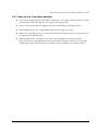
Appendix C Character Code Table
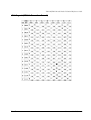
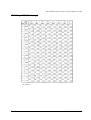
C.1 Page 0 (PC437 : USA, Standard Europe) . . . . . . . . . . . . . . . . . . . . . . . . . . . . . . . . . . . . . . . . . . . . . . . . .
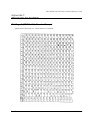
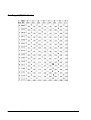
C.2 Page 1 (Katakana) . . . . . . . . . . . . . . . . . . . . . . . . . . . . . . . . . . . . . . . . . . . . . . . . . . . . . . . . . . . . . . . . . . .
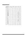
C.3 Page 2 (PC850: Multilingual) . . . . . . . . . . . . . . . . . . . . . . . . . . . . . . . . . . . . . . . . . . . . . . . . . . . . . . . . . . .
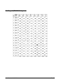
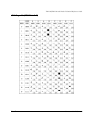
C.4 Page 3 (PC860: Portuguese) . . . . . . . . . . . . . . . . . . . . . . . . . . . . . . . . . . . . . . . . . . . . . . . . . . . . . . . . . . .
C.5 Page 4 (PC863: Canadian-French) . . . . . . . . . . . . . . . . . . . . . . . . . . . . . . . . . . . . . . . . . . . . . . . . . . . . .
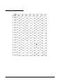
C.6 Page 5 (PC865: Nordic) . . . . . . . . . . . . . . . . . . . . . . . . . . . . . . . . . . . . . . . . . . . . . . . . . . . . . . . . . . . . . . .
C.7 Page 16 (WPC1252) . . . . . . . . . . . . . . . . . . . . . . . . . . . . . . . . . . . . . . . . . . . . . . . . . . . . . . . . . . . . . . . . . .
C.8 Page 17 (PC866: Cyrillic #2) . . . . . . . . . . . . . . . . . . . . . . . . . . . . . . . . . . . . . . . . . . . . . . . . . . . . . . . . . . . .
C.9 Page 18 (PC852: Latin2) . . . . . . . . . . . . . . . . . . . . . . . . . . . . . . . . . . . . . . . . . . . . . . . . . . . . . . . . . . . . . . .
C-1
C-2
C-3
C-4
C-5
C-6
C-7
C-8
C-9
TM-L90/TM-L90 with Peeler Technical Reference Guide
C.10 Page 19 (PC858: Euro) . . . . . . . . . . . . . . . . . . . . . . . . . . . . . . . . . . . . . . . . . . . . . . . . . . . . . . . . . . . . . . . C-10
C.11 Page 255 (Blank page) . . . . . . . . . . . . . . . . . . . . . . . . . . . . . . . . . . . . . . . . . . . . . . . . . . . . . . . . . . . . . . C-11
C.12 International Character Set . . . . . . . . . . . . . . . . . . . . . . . . . . . . . . . . . . . . . . . . . . . . . . . . . . . . . . . . . . . C-12
Appendix D Option Specifications
D.1 PS-180 . . . . . . . . . . . . . . . . . . . . . . . . . . . . . . . . . . . . . . . . . . . . . . . . . . . . . . . . . . . . . . . . . . . . . . . . . . . . . .
D.1.1 Electrical Characteristics . . . . . . . . . . . . . . . . . . . . . . . . . . . . . . . . . . . . . . . . . . . . . . . . . . . . . . . . .
D.1.2 Case Specifications . . . . . . . . . . . . . . . . . . . . . . . . . . . . . . . . . . . . . . . . . . . . . . . . . . . . . . . . . . . . .
D.1.2.1 Material . . . . . . . . . . . . . . . . . . . . . . . . . . . . . . . . . . . . . . . . . . . . . . . . . . . . . . . . . . . . . . . . . .
D.1.3 AC Cable Selection . . . . . . . . . . . . . . . . . . . . . . . . . . . . . . . . . . . . . . . . . . . . . . . . . . . . . . . . . . . . .
D-1
D-1
D-1
D-2
D-2
Appendix E Maintenance
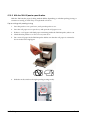
E.1 Cleaning the autocutter (TM-L90 only) . . . . . . . . . . . . . . . . . . . . . . . . . . . . . . . . . . . . . . . . . . . . . . . . . . . E-1
E.2 Print Head Cleaning . . . . . . . . . . . . . . . . . . . . . . . . . . . . . . . . . . . . . . . . . . . . . . . . . . . . . . . . . . . . . . . . . . E-3
E.3 Cleaning the peeler (TM-L90 peeler specification only) . . . . . . . . . . . . . . . . . . . . . . . . . . . . . . . . . . . . . E-5
Appendix F Troubleshooting
F.1 Panel LED and Error Status . . . . . . . . . . . . . . . . . . . . . . . . . . . . . . . . . . . . . . . . . . . . . . . . . . . . . . . . . . . . .
F.1.1 Power (POWER) LED . . . . . . . . . . . . . . . . . . . . . . . . . . . . . . . . . . . . . . . . . . . . . . . . . . . . . . . . . . . . . .
F.1.2 No Roll Paper (PAPER OUT) LED . . . . . . . . . . . . . . . . . . . . . . . . . . . . . . . . . . . . . . . . . . . . . . . . . . . .
F.1.3 Error (ERROR) LED . . . . . . . . . . . . . . . . . . . . . . . . . . . . . . . . . . . . . . . . . . . . . . . . . . . . . . . . . . . . . . . .
F.1.4 Error code . . . . . . . . . . . . . . . . . . . . . . . . . . . . . . . . . . . . . . . . . . . . . . . . . . . . . . . . . . . . . . . . . . . . . .
F.2 The autocutter is jammed or the roll paper cover will not open (TM-L90 only) . . . . . . . . . . . . . . . . . .
F.3 When a paper jam occurs (TM-L90 peeler specification) . . . . . . . . . . . . . . . . . . . . . . . . . . . . . . . . . . . .
F.4 The printer became inoperative after you change the interface reset signal
in the memory switch setting mode . . . . . . . . . . . . . . . . . . . . . . . . . . . . . . . . . . . . . . . . . . . . . . . . . . . . . . . .
Appendix G Shipping Procedures
F-1
F-1
F-2
F-2
F-3
F-8
F-9
F-9
TM-L90/TM-L90 with Peeler Technical Reference Guide
Chapter 1
Product Overview
1.1 Product Structure
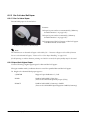
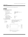
1.1.1 Models
❏ Product name:
•
TM-L90 series/ TM-L90 peeler specification
Printing
Thermal line
Serial interface (RS-232C)
Parallel interface (IEEE-1284 standard)
USB interface (Supports USB full speed mode (12Mbps))
Ethernet interface specification
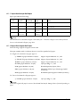
1.1.2 Accessories
TM-L90
❏ Printer
❏ Label roll paper
❏ User’s manual
❏ Power switch cover
❏ Control panel label used for horizontal installation
❏ Paper exit guide for horizontal installation
❏ Roll paper spacer
❏ Screw for installation of the roll paper spacer
❏ Hexagonal lock screws (2 pieces) (only for the serial interface)
TM-L90 peeler specification
❏ Printer (main unit)
❏ Label roll paper
❏ User's manual
❏ Power switch cover
❏ Operation label (an instruction label for the peeler open lever and the roll paper cover open
lever)
❏ Roll paper spacer
Rev. B
Product Overview 1-1
1.1.3 Option
TM-L90
❏ Velcro affixing tapes (model: DF-10)
❏ Wall hanging bracket (model: WH-10)
❏ External power supply unit EPSON PS-180 (*1)(PS-180 supports power-saving feature)
❏ Power cables (model: AC-170)
(*1) Power supply unit doesn’t come with the printer. Purchase separately if needed.
TM-L90 peeler specification
❏ Velcro for anchoring the printer (part number: DF-10)
❏ Wall fixture (part number: WH-10)
❏ External power unit Epson PS-180 (*1) (PS-180 is an energy saving item)
❏ Various interface boards (UB series excluding UB-U05)
(*1) The power unit is not included. Please purchase it separately.
1-2 Product Overview
Rev. B
TM-L90/TM-L90 with Peeler Technical Reference Guide
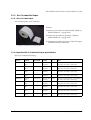
1.2 Name and Description of Each Part
1.2.1 Part Names (TM-L90)
cutter cover
power switch
manual cutter
roll paper cover
open lever
Perforation to pass
the cables through
roll paper cover
control panel
FEED Button
Printer Part Names
* Refer to page 2-19 for the location of the DIP switches.
* Another FEED button is located under the roll paper cover. Refer to page 2-23 for the location.
Rev. B
Product Overview 1-3
1.2.2 Part names (TM-L90 peeler specification)
cutter cover
power switch
label peeling
sensor
peeler cover
open lever
manual cutter
roll paper cover
open lever
peeler cover
FEED Button
wiring knockout
control panel
roll paper cover
Part Names of TM-L90 Peeler Specification
* Refer to page 2-19 for the DIP switch positions.
* There is also a FEED button under the roll paper cover. Refer to page 2-23 for the position.
1-4 Product Overview
Rev. B
TM-L90/TM-L90 with Peeler Technical Reference Guide
1.2.3 Control Panel
FEED Button
PAPER OUT LED
ERROR LED
POWER LED
FEED button (with TM-L90)
Pressing the FEED button feeds the roll paper.
The printer paper feed depends on the line feed amount set. However, in the following cases,
FEED cannot be used for paper feed.
•
When the roll paper cover is open
•
When performing cleaning
•
When performing self-testing (Press the FEED button to stop self-testing and press it
again to resume it.)
•
When the FEED button has a defined function in a macro definition command.
(When using ESC/POS commands)
FEED button (with the TM-L90 peeler specification)
FEED has the following 3 functions.
•
Feeding roll paper
•
Initializing the mechanism
(After closing the roll paper cover, the status changes to waiting to print when FEED is
pressed)
•
Recovering from errors
❏ Feeding roll paper
The printer paper feed depends on the line feed amount set. However, in the following cases,
FEED cannot be used for paper feed.
Rev. B
•
The roll paper runs out
•
When the roll paper cover is open
•
When waiting for label removal
•
When waiting for FEED to be pressed
•
When an error occurs
Product Overview 1-5
❏ Initializing the mechanism(with TM-L90)
You can initialize the mechanism (paper feed operation) with the following procedure.
1. Open the roll paper cover.
2. Close the roll paper cover.
3. Press FEED.
•
If the roll paper is inserted after the roll paper cover is opened and closed, the printer
waits for FEED to be pressed, and then the PAPER OUT LED flashes. In this case, press
FEED.
•
Caution: When memory switch 8-6 is set to "ON," If the roll paper is inserted when the
power is off, or if the roll paper cover is opened and closed then the power is turned on,
press FEED.
❏ Recovering from errors
When error recovery with FEED is enabled by memory switch 8-1, pressing FEED when a paper
layout error occurs recovers from the error and performs automatic paper layout.
❏ Initializing the mechanism(with TM-L90 with Peeler)
You can initialize the mechanism (paper feed operation) with the following procedure.
1. Open the peeler cover.
2. Open the roll paper cover.
3. Close the peeler cover and the roll paper cover.
4. Press FEED.
•
If the roll paper is inserted after the roll paper cover is opened and closed, the printer
waits for FEED to be pressed, and then the PAPER OUT LED flashes. In this case, press
FEED.
•
Caution: When memory switch 8-6 is set to "ON," If the roll paper is inserted when the
power is off, or if the roll paper cover is opened and closed then the power is turned on,
press FEED.
❏ Recovering from errors
When error recovery with FEED is enabled by memory switch 8-1, pressing FEED when a paper
layout error occurs recovers from the error and performs automatic paper layout.
1-6 Product Overview
Rev. B
TM-L90/TM-L90 with Peeler Technical Reference Guide
PAPER OUT LED (with TM-L90)
❏ Lights when there is no more roll paper or there is little remaining.
(Default setting. The LED condition varies according to the memory switch settings. Refer to
“Starting the Memory Switch Setting mode” on page 2-23 and“Error code” on page F-3 for
details.)
❏ Off when there is a sufficient amount of roll paper remaining.
(Default setting. The LED condition varies according to the memory switch settings. Refer to
“Starting the Memory Switch Setting mode” on page 2-23 and“Error code” on page F-3 for
details.)
❏ Flashes when a self test is in progress or when the printer waits for the macro execution
switch to go on.
PAPER OUT LED (with the TM-L90 peeler specification)
❏ Lights when there is no more roll paper or there is little remaining.
(Default setting. The LED condition varies according to the memory switch settings. Refer to
“Starting the Memory Switch Setting mode” on page 2-23 and“Error code” on page F-3 for
details.)
❏ Off when there is a sufficient amount of roll paper remaining.
(Default setting. The LED condition varies according to the memory switch settings. Refer to
“Starting the Memory Switch Setting mode” on page 2-23 and“Error code” on page F-3 for
details.)
❏ Flashes when a self test is in progress or when the printer waits for the macro execution
switch to go on.
❏ When the roll paper is inserted and the roll paper cover is closed, one label is ejected and the
LED starts flashing. It flashes until FEED is pressed.
❏ When a label is issued, flashing starts after it is issued. The LED flashes until the label is
removed from the peeler.
POWER LED
❏ Lights when the power supply is on.
❏ Off when the power supply is turned off.
❏ Flashes during execution of each operation.
ERROR LED
❏ Lights when the printer is offline.
❏ Off under normal conditions.
❏ Flashes when an error occurs. (Refer to “Error code” on page F-3 for details)
1.2.4 Power Switch
Refer to “Printer Part Names” on page 1-3 for the power switch location.
Turn on the power by holding down the POWER button 1 second or longer. Turn off the power
by holding down the POWER button 3 seconds or longer.
Rev. B
Product Overview 1-7
The printer is normally turned on/off with this switch. You can select whether to enable or
disable the power switch using the DIP switches.
When the DIP switches are set to OFF (power switch enabled), the power switch controls the TM
printer as follows.
When the TM is turned off:
The TM is powered ON when the power supply switch is pressed more than 1 second.
When the TM is turned on:
The TM is powered OFF when the power supply switch is pressed more than 3 seconds.
If for some reason pressing the power switch even more than 10 seconds does not turn the
power off, the TM executes a forced power off.
Note:
When the DIP switches are set to ON (power switch disabled), use direct control of the printer with ESC/
POS commands. (For details, refer to “TM Printer Operation Performed When Power Supply Switch is
Disabled” on page 5-1.) The printer may not operate normally when using OPOS or the Advanced
Printer Driver with the DIP switches set to ON.
Note:
When using OPOS or the Advanced Printer Driver, do not set the DIP switches to ON (power switch
disabled). The printer may not operate normally if the DIP switches are set to ON.
Note:
Make sure to check whether the AC adapter is connected to the power supply before turning on the power
switch of the printer.
1.2.5 Power switch cover
To prevent unintentional contact or improper changes and to improve the appearance, use a
cover. When using the power switch cover, to reset the TM printer, press the power switch
through the hole in the power switch cover.
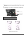
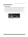
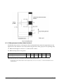
1.2.6 Mode switch (TM-L90 peeler specification only)
With the TM-L90 peeler specification, you can select the peeling issuing mode and continuous
issuing mode with the mode switch. The mode switch switches between the peeling issuing
mode and continuous issuing mode.
The mode switch is inside the top left of the printer when the roll paper cover is opened.
Note:
Be sure that the peeler cover and the roll paper cover are open when switching the modes. The
setting is effective when the power is turned on or the covers are closed. If the mode is switched
with the covers closed, the setting will not be changed.
Be sure not to use a ball point pen to switch the modes. A ball point pen can damage the switch.
1-8 Product Overview
Rev. B
TM-L90/TM-L90 with Peeler Technical Reference Guide
mode switch
To use the peeling issuing mode, move the mode switch to the right.
To use the continuous issuing mode, move the mode switch to the left.
Rev. B
Product Overview 1-9
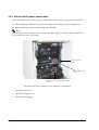
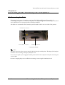
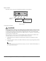
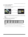
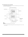
1.2.7 Connectors
Remove the bottom of the cover as shown in the illustration below. All cables are connected to
the connector panel located on the lower rear side of the printer.
power
drawer kick-out
interface
Connector Panel
Note:
The model pictured is a serial interface model. For other information on interfaces and connectors, refer to
“Connecting the Cable” (Chapter 3)
1-10 Product Overview
Rev. B
TM-L90/TM-L90 with Peeler Technical Reference Guide
Chapter 2
Setup
2.1 Setup Flow
Before using the printer, you need to set various settings to increase the printer's functionality.
Configure the printer appropriately depending on the environment.
Determine how to install the printer (install it vertically or horizontally)
↓
Set the Roll Paper Near-End Detector
↓
Connect the power supply
↓
Autocutter settings (TM-L90 only)
↓
Set the Roll Paper width
↓
DIP switch settings
↓
Memory switch settings
↓
Set the Paper layout
Rev. B
Setup 2-1
2.2 Installation Procedures
2.2.1 Precaution For Installation
❏ TM-L90
•
Locate the printer on a flat surface, whichever orientation you choose.
•
Avoid locations susceptible to dust and other foreign matter.
•
Make sure to avoid bumping or otherwise exposing the printer to strong impact during
operation.
•
Avoid resting the printer on the power supply or other cables or other objects.
•
Consider vibration during paper cutting and drawer usage. Take measures to prevent
the printer from moving.
❏ TM-L90 peeler specification
•
Locate the printer on a flat surface, whichever orientation you choose.
•
Avoid locations susceptible to dust and other foreign matter.
•
Make sure to avoid bumping or otherwise exposing the printer to strong impact during
operation.
•
Avoid resting the printer on the power supply or other cables or other objects.
•
Consider vibration during paper cutting and drawer usage. Take measures to prevent
the printer from moving.
•
To prevent malfunction of the label peeling sensor, do not locate the printer in direct
sunlight.
2-2 Setup
Rev. B
TM-L90/TM-L90 with Peeler Technical Reference Guide
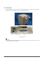
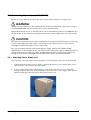
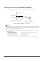
2.2.2 Instructions for Installation
The TM-L90 can be placed vertically (paper outlet in front), horizontally (paper outlet at the
top), or attached to a wall (using the optional wall hanging set WH-10).
With the TM-L90 with peeler, you can use it vertically or wall mounted with either peeling
issuing or with continuous issuing (not using the peeler).
Note:
For the TM-L90 with Peeler, horizontal installation is prohibited to avoid jams caused by re-sticking of
backing paper and a label.
The illustration below shows the vertical installation for the TM-L90 with Peeler.
Note:
To hang the printer on the wall, see the Wall Hanging Bracket Set Installation Manual provided with the
WH-10 for instructions.
It is recommended to take some measures so that the printer will be stable when paper is being loaded or a
drawer is being used. The DF-10 (velcro fastening) for fixing the printer is provided as an option.
When using the printer with the peeling issuing mode, be sure to install the printer so that a peeled label
will not contact the used backing paper. Re-sticking of a peeled label to the backing paper will cause jams.
Rev. B
Setup 2-3
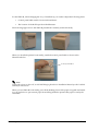
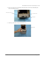
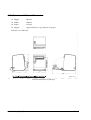
For the TM-L90, when changing the way of installation, you need to adjust the following items:
•
Control panel label used for horizontal installation
•
The location of the Roll Paper Near-End Detector
The following figure shows the TM-L90 placed both vertically and horizontally.
When you install the printer horizontally, attach the control panel label as shown in the
illustration below.
Control panel label
Note:
To hang the printer on the wall, see the Wall Hanging Bracket Set Installation Manual provided with the
WH-10 for instructions.
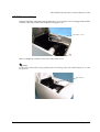
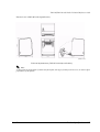
When you use TM-L90 horizontally, peel off the backing sheet of the paper exit guide and attach
it as shown below to prevent cut paper from falling inside the printer after paper is cut by the
autocutter.
2-4 Setup
Rev. B
TM-L90/TM-L90 with Peeler Technical Reference Guide
CAUTION:
When using the paper exit guide, do not use roll paper with a core that is smaller than
the specification (inside diameter: 25.4 mm, outside diameter: 31.4 mm). Using a smaller
one may cause a paper jam at the attached paper exit guide.
paper exit guide
Rev. B
Setup 2-5
2.3 Adjusting Roll Paper Near-End Detection Position
2.3.1 With TM-L90
Below are three situations when roll paper N.E. detector adjustment is required.
❏ When changing the way of installation. (Vertically⇔Horizontally)
❏ To adjust the location of detection to suit the diameter of the roll paper core used.
❏ To adjust the amount of remaining paper desired.
Note:
Roll paper centers are manufactured according to various specifications, making it impossible to exactly
detect the remaining amount of paper.
N.E. detector holder
Detector adjustment screw
N.E. detector window
when installing vertically
N.E. detector
(location when
installing horizontally)
Part names and the locations of N.E. detector components
1. Open the roll paper cover.
2. Remove the roll paper.
2-6 Setup
Rev. B
TM-L90/TM-L90 with Peeler Technical Reference Guide
3. Loosen the detector adjustment screw using a coin or similar tool.
Detector
adjustment
screw
4. The adjustment position of the roll paper Near-End detector changes depending on the way
of installation. In either case (vertical or horizontal), adjust the detector so that its tab comes
out from the hole near the bottom of the printer. (Refer to “Adjusting Roll Paper Near-End
Detection Position” on page 2-6, “Adjustment Positions of N.E. Detector” on page 2-8
Move the N.E. detector
holder in the direction
of the arrow to make
the detector come out
from the window for
either vertical or
horizontal installation.
Note:
When changing the position of the N.E. detector in accordance with the change of installation, move the
roll paper N.E. detector as the above arrow shows while holding down the detector.
Rev. B
Setup 2-7
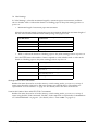
5. To fine tune the amount of remaining paper that is detected by the N.E. detector, move the
N.E. detector holder shown in the illustration “N.E. Detector Holder” on page 2-8 and adjust
the position.
Note:
Note that the direction to move the roll paper N.E. detector varies depending on the method of printer
installation (vertical/horizontal).
Adjustment direction for
vertical installation
N.E. detector holder
Adjustment direction for
horizontal installation
N.E. Detector Holder
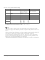
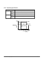
Adjustment Position Number
Specified Thermal Paper Dimension
#1
Approximately 36 mm {1.42"}
#2
Approximately 41 mm {1.61"}
Holder Position #1 for horizontal
Holder Position #2 for horizontal
Holder Position #1 for vertical
Holder Position #2 for vertical
Adjustment Positions of N.E. Detector
2-8 Setup
Rev. B
TM-L90/TM-L90 with Peeler Technical Reference Guide
6. Tighten the detector adjustment screw using a coin or similar tool.
7. Move the N.E. detect lever by hand (finger) to confirm that it moves freely.
Check that the N.E. detect lever
is operating properly.
8. Load the roll paper.
9. Close the roll paper cover.
Rev. B
Setup 2-9
2.3.2 With the TM-L90 peeler specification
In the following 2 cases, it is necessary to adjust the position of the roll paper near end sensor.
❏ When adjusting the detection position according to the thickness of the roll paper core
❏ When adjusting the amount remaining paper desired
Note:
Since the shape of the central part of the roll paper may differ slightly according to the specification, it is
not possible to detect near end exactly.
near end sensor
holder
sensor adjustment
screw
near end sensor window (the photo
shows the sensor projecting from the
window)
Part names and the locations of N.E. detector components
1. Open the peeler cover.
2. Open the roll paper cover.
3. Take out the roll paper.
2-10 Setup
Rev. B
TM-L90/TM-L90 with Peeler Technical Reference Guide
4. Using a coin or similar object, loosen the sensor adjustment screw.
sensor
adjustment
screw
5. Adjust the roll paper near end sensor so that the claw of the roll paper near end sensor
projects from the hole near the bottom of the device. (Refer to “Part names and the locations
of N.E. detector components” on page 2-6 and “Near end sensor adjustment position” on
page 2-12.)
Adjust the sensor so that it
projects from the window.
6. To make fine adjustments to the amount of paper remaining detected by the roll paper near
end sensor, finely adjust the position of the near end sensor holder by moving it in the
direction of the arrows as shown in the figure “N.E. Detector Holder” on page 2-8.
Rev. B
Setup 2-11
Note:
Move the N.E. detector in the direction shown by arrow.
Adjustment direction
N.E. detector holder
Near end sensor holder
Adjustment scale
Outside diameter of specified thermal paper
#1
Approximately 36 mm {1.42"}
#2
Approximately 41 mm {1.61"}
Note:
Adjust the sensor while checking the position of the parts circled in the following figure.
when the sensor holder position is #1
when the sensor holder position is #2
Near end sensor adjustment position
2-12 Setup
Rev. B
TM-L90/TM-L90 with Peeler Technical Reference Guide
7. Using a coin or similar object, tighten the sensor adjustment screw.
8. Push the near end sensor with your finger and check that it moves smoothly.
push the near end sensor with
your finger and check that it
moves smoothly
9. Set the roll paper.
10. Close the roll paper cover.
Rev. B
Setup 2-13
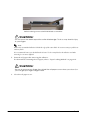
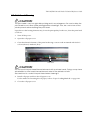
2.4 Connecting Power Supply Unit (PS-180)
Be sure to use the EPSON PS-180 or the equivalent product as the power supply unit.
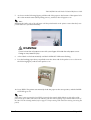
WARNING:
Always use the EPSON PS-180 or equivalent product as the power supply unit. Using a
nonstandard power supply can result in shocks and even fire.
Should a fault ever occur in the EPSON PS-180 or equivalent product, immediately turn
off the power to the printer and remove the power supply cable from the wall socket.
CAUTION:
Be sure to remove the power supply cable from the wall socket whenever connecting
or disconnecting the power supply unit to the printer. Failure to do so may result in
damage to the power supply unit or the printer.
Be sure to confirm that the wall socket power supply satisfies the rated voltage
requirements of the power supply unit. Never insert the power supply cable plug into a
socket that does not meet the rated voltage requirements of the power supply unit.
Doing so may result in damage to both the power supply unit and the printer.
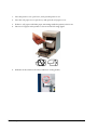
2.4.1 Attaching Power Supply Unit
The following is an explanation of the procedure for attaching the power unit to the TM-L90.
1. Confirm that the printer's power supply is turned off and the power supply unit's power
cable has been removed from the wall socket.
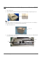
2. To place cables, first break off by hand any of the three perforations to pass the cables
through indicated by circles in the illustration (the other one is on the right). Then put the
cables through the holes and replace the bottom of the cover.
2-14 Setup
Rev. B
TM-L90/TM-L90 with Peeler Technical Reference Guide
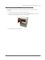
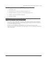
3. Remove the bottom of the cover as shown in the illustration below.
4. Install the connector of the power supply cable onto the power supply connector (labeled
DC24V).
Power supply connector
Power Supply Connector
Note:
When removing the DC cable connector from the EPSON PS-180, first confirm that the power supply
cable has been disconnected from the power supply unit; then grasp the arrow marked section of the
connector and pull straight out.
2.4.2 Caution about Power Supply unit and Supply Voltage
❏ ERROR LED flashes when a high voltage or low voltage error occurs. In such cases,
immediately turn the power off.
Rev. B
Setup 2-15
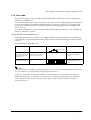
2.5 Autocutter settings (TM-L90 only)
The TM-L90 has an autocutter attached for cutting the paper. The autocutter can perform 2 cuts,
"partial cut," in which a small part is left uncut on the left edge, and "full cut" (default setting), in
which the paper is cut completely. By adjusting the attachment position of the cutter unit, you
can select between "partial cut" and "full cut."
Note:
You can't configure the autocutter setting (Partial cut/Full cut) through a software command.
You can't change from partial cut setting to full cut setting after using the printer with partial cut
setting. Since the partial cut doesn't use the tip of the blade, it might have deteriorated. Contact the
nearest EPSON service center if you'd like to do the above change.
To disable the autocutter, change the memory switch (MSW2-2) settings. (Refer to “Setting Memory
Switches” on page 2-23).
Performing full cut without the paper exit guide when the printer installed horizontally may cause a
double-cut, paper jam or autocutter error because a cut sheet may drop in the paper path. Be sure to attach
the paper exit guide when performing a full cut in the horizontal installation. (Refer to “Instructions for
Installation” on page 2-3 for instructions on attaching the guide.)
1. Turn off the power.
2. Press the roll paper cover open lever, and open the roll paper cover.
3. Push the body case outward (in the direction of the 2 arrows) and remove the cutter cover.
cutter cover
2-16 Setup
Rev. B
TM-L90/TM-L90 with Peeler Technical Reference Guide
4. Remove the single screw retaining the cutter unit and loosen the screw indicated by the
circle in the illustration below.
Remove this screw
Loosen this screw
Cutter unit
5. Lift the top of the cutter unit upward and remove it.
Lift upwards
Rev. B
Setup 2-17
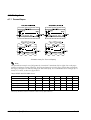
6. Moving the cutter unit in a lateral direction, shift to the dowel position of the desired cut
method.
Shift to dowel of
desired cut
method
dowels
P
F
Partial cut
P
F
Full cut
7. Secure the cutter unit again using the removed screw and the loosened screw.
8. Install the cutter cover.
9. Close the roll paper cover.
2-18 Setup
Rev. B
TM-L90/TM-L90 with Peeler Technical Reference Guide
2.6 Setting Roll Paper Width
The TM-L90 / TM-L90 peeler specification uses a roll paper 80 mm wide in the default state.
When using a roll paper 38 to 70 mm wide with this printer, attach the roll paper spacer in
accordance with the following procedure.
Note:
If a printer has already been used, the paper width cannot be changed from narrow to wide. This is because
the part of the head that made direct contact with the platen may have been damaged when narrow roll
paper was used. The paperless part of the cutter blade may also have worn.
Only when the printer is not yet used can the paper width be changed from narrow to wide.
The following explains the procedure for setting the roll paper width for the TM-L90.
1. When using 61 mm to 70 mm roll paper, break off the two tabs of the roll paper spacer.
Note:
You can still use widths from 38 mm to 60 mm after breaking the tabs off.
tabs
2. Open the roll paper cover.
Rev. B
Setup 2-19
3. As shown below, insert the roll paper spacer so that the front edge goes through the notch in
the printer, and fit the protrusion of the roll paper spacer on the shaft.
notch
front edge
shaft
protrusion
4. Push the roll paper spacer until it clicks.
Note:
Check that the roll paper spacer slides smoothly from side to side.
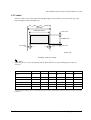
5. Slide the roll paper spacer side-to-side and set it to the appropriate position. Use the
measurement lines if necessary.
Note:
Roll paper is placed on the tab-free side of the roll paper spacer.
When positioning the roll paper spacer, provide 0.5 mm of room for the maximum roll paper width.
screw
measurement
6. Secure the roll paper spacer with the supplied screw. (See above.)
7. Set the paper width using any of various drivers, the memory setup utility or the memory
switch setting mode.
(For the memory switch setting mode, refer to “Setting Memory Switches” on page 2-23.
2-20 Setup
Rev. B
TM-L90/TM-L90 with Peeler Technical Reference Guide
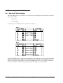
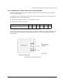
2.7 DIP Switch Settings
With the TM-L90 / TM-L90 peeler specification, you can make various settings with the DIP
switches. The DIP switches are inside the roll paper cover.
DIP switch cover
Before setting DIP switches, remove the DIP switch cover.
Note:
Set the DIP switches after turning off the printer. The settings will not be enabled if they are set with
the power on.
DIP switches
Rev. B
Setup 2-21
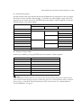
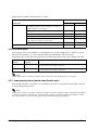
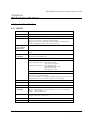
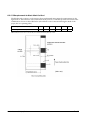
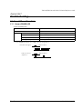
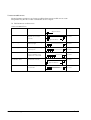
DIP switch settings (Serial interface model)
Switch No.
Function
ON
OFF
1
Enable/disable Power switch.
Switches power supply On/Off
using commands. (Power
supply switch is disabled.)
Power supply switch is used to
switch power On/Off.
2
Select for serial communication
condition.
Set using DIP switch
1-7, 1-8
Set using memory switches.
3
Handshake
XON/XOFF
DTR/DSR
4
Bit length
7 bits
8 bits
5
Parity check
Yes
No
6
Parity type
Even
Odd
7
Baud rate (bps)
8
7
ON
OFF
ON
OFF
8
ON
ON
OFF
OFF
:2400
:4800
:9600
:19200
bps: Indicates the number of bits transferred per second.
DIP switches 2 to 8 are for serial communication. Not used in parallel communication.
Note:
When using an OPOS or Advanced Printer Driver, do not change the DIP switch 1-1 from the OFF
position (power supply switch enabled). The printer may not operate normally if the DIP switches are set
to ON.
When you set the baud rate with the memory switch, you can set faster communication than with the DIP
switch. (Refer to “Communication Condition” on page 2-29, “Error code” on page F-3)
In serial communication, intermittent printing* may occur. This is because when the communication
speed is low, a data transmission waiting state occurs frequently since the printing mechanism speed is
high. Increasing the communication speed may reduce this symptom.
* Intermittent printing: White streaks as large as one or two hairs appear horizontally in a printing result.
2-22 Setup
Rev. B
TM-L90/TM-L90 with Peeler Technical Reference Guide
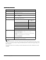
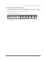
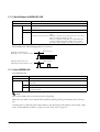
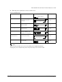
DIP switch settings (Parallel, USB, Ethernet model)
Switch No.
Function
ON
OFF
1
Enable/disable Power switch.
Switches power supply On/Off
using commands. (Power
supply switch is disabled.)
Power supply switch is used to
switch power On/Off.
2
Reserved
Fixed to on
--
3
Reserved
--
Fixed to off
4
Reserved
--
Fixed to off
5
Reserved
--
Fixed to off
6
Reserved
--
Fixed to off
7
Reserved
--
Fixed to off
8
Reserved
--
Fixed to off
bps: Indicates the number of bits transferred per second.
DIP switches 2 to 8 are for serial communication. Not used in parallel communication.
Note:
When using an OPOS or Advanced Printer Driver, do not change DIP switch 1-1 from the OFF position
(power supply switch enabled). The printer may not operate normally if the DIP switches are set to ON.
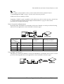
2.8 Setting Memory Switches
With the TM-L90 / TM-L90 peeler specification, you can make various other settings with the
software settings saved in the non-volatile memory inside the printer called the memory
switches.
The memory switches can be set in 2 ways, using the memory switch setting mode of the printer,
or from the application. Depending on the setting items, some settings can only be set from the
application.
Note:
When using the OPOS or Advanced Printer Driver, it is generally unnecessary to set the memory
switches. However, set the memory switches in either of the following cases.
• When you want to set the communication speed (38,400/57,600/115200 bps) higher than that
available with the DIP switches in serial communication speed setting
• When you set the thermal paper width and select single color or two colors (when using the
Advanced Printer Driver)
* For thermal paper width setting and single color/two colors selection in the OPOS ADK, you
need not set the memory switches separately since the memory switches are automatically set by
making changes with the Setup POS Utility packed with OPOS ADK.
(For the OPOS and Advanced Printer Drivers, refer to “Introduction of Control Methods” on
page 4-1.
Rev. B
Setup 2-23
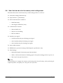
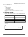
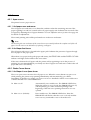
2.8.1 Items that can be set in the memory switch setting mode
The items that can be set in the memory switch setting mode are as follows.
❏ Autocutter settings (TM-L90 only)
❏ Paper selection / print density
❏ Serial communication conditions
•
Baud Rate Setup
•
data length, handshake, Parity
❏ Communication related
•
Receive buffer size
•
Receive error handling
•
BUSY conditions
❏ Interface reset signal
•
Parallel interface #31 pin: Selecting reset signal
•
Serial interface #25 pin: Selecting reset signal
•
Serial interface #6 pin: Selecting reset signal
❏ Paper width selection
❏ FEED button operational settings (TM-L90 peeler specification only)
❏ Label Settings
•
Maximum length of automatic paper measurement
•
With or without the function of feeding paper to the print starting position at power on
•
Recovery from paper layout error
Note:
Turning off the power supply in the memory switch setting mode clears all settings. After performing the
complete operation, turn off the power using the correct procedure.
2-24 Setup
Rev. B
TM-L90/TM-L90 with Peeler Technical Reference Guide
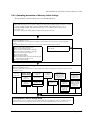
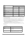
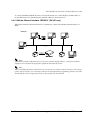
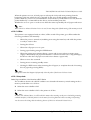
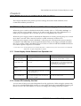
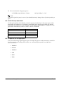
2.8.2 Starting the Memory Switch Setting mode
Use the following procedure to start the memory switch setting mode.
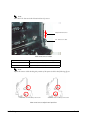
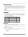
1. For the TM-L90, open the roll paper cover. For the TM-L90 with Peeler, open the peeler
cover and the roll paper cover.
2. Load roll paper.
3. Turn on the power while pressing FEED inside the printer. Keep pressing FEED until the
POWER, ERROR, and PAPER OUT LEDs all come on. The figure shows the TM-L90.
Paper FEED button
(inside the printer)
The location of the FEED button (inside the roll paper cover)
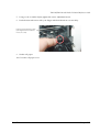
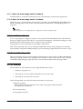
4. While the POWER, ERROR, and PAPER OUT LEDs are on, press FEED inside the printer
twice.
5. Close the cover. The printer will print out a guidance for the memory switch setting mode
and then enter the memory switch setting mode.With the peeling issuing mode, after closing
the roll paper cover, the PAPER OUT LED flashes. After inserting the label into the peeler
path, press FEED.
6. Follow the guidance to use the mode. (Refer to the flowchart “Operating procedure of
Memory Switch Settings” on page 2-27)
Rev. B
Setup 2-25
2.8.3 Ending Memory Switch Setting mode
Once the setting is completed, the contents of the setting are stored; then the printer executes the
initialization. When initialization is finished, the printer returns to normal operating mode.
Note:
We recommend that you to perform the memory switch setting after finishing the paper layout setting
since the roll paper cover needs to be opened and closed for the memory switch setting. For paper layout
settings, refer to “Setting Paper Layout” on page 2-45.
When executing the memory switch setting mode without setting the paper layout, paper is fed every time
the roll paper cover is opened and closed, so paper is wasted.
When you'd like to change the memory switch settings with paper layout unchanged, it is better to change
it using the memory switch setting utility or other means.
2-26 Setup
Rev. B
TM-L90/TM-L90 with Peeler Technical Reference Guide
2.8.4 Operating procedure of Memory Switch Settings
The procedures used for this process are described below.
Entering Memory Switch Settings Mode
1.Open the roll paper cover, and turn on the power while pressing FEED inside the printer. You need
to keep pressing the FEED button until the POWER, ERROR, and PAPER OUT LED come on.
2.While the POWER, ERROR, and PAPER OUT LEDs are on, press FEED inside the printer twice.
3.Close the cover.
The current setting and setting guidance will be printed automatically.
Selecting Items to Set
Open the roll paper cover.
Select setting items according to the number of times FEED is pressed, and close the roll paper
cover.
Pressing the FEED button 0 times or 12 or more times will terminate this procedure.
❒1 time: Autocutter (TM-L90 only)
❒2 times: Paper/Print Density
❒3 times: Basic Serial Interface Settings
❒4 times: Advanced Interface Settings
❒6 times: Interface Reset Signal
❒7 times: Paper Width
❒8 times: Other Settings
❒9 times: FEED button operational settings (TML90 peeler specifications only)
❒11 times: Label Settings
No change for numbers other
than at left
Selecting Individual Settings
Open the roll paper cover.
Press the FEED button the number of times required to select the setting for each item; then close the
roll paper cover.
Autocutter(TM
-L90 only)
(page 2-28)
Selection of Paper
and Print density
Serial
communication
condition
Selection of
Paper
(page 2-28)
Baud Rate Setup
(page 2-29)
Selection of Print
density
(page 2-28)
Data Length,
Handshake or Parity
(page 2-30)
Communication
related
Condition
(page 2-30)
FEED button
operational settings
(TM-L90 peeler
specifications only)
(page 2-33)
Interface reset
signal
(page 2-31)
Other settings
Setting PAPER
OUT LED
(page 2-32)
Paper layout
error recovery
methods
(page 2-32)
Label Settings
Maximal length of
paper automeasurement
(page 2-34)
With or without the
function of feeding
paper to the print
starting position at
power on
(page 2-34)
Ending Memory Switch Settings Mode
Turn the power off. The printer prints new settings and save the settings to the non-volatility memory.
Then the software is reset and the printer enters the normal printable status. Turn the power off.
Rev. B
Setup 2-27
Selecting individual settings
❏ Setting autocutter (TM-L90 only)
First, select the setting for the paper to use by the number of times FEED is pressed. Press the
FEED button the number of times required to select the desired autocutter setting.
Press FEED button
Setting to select
0 times:
No change
1 time:
Installed
2 times:
Not Installed
3 or more times:
No Change
❏ Selection of Paper and Print density
First, select the setting for the paper to use by the number of times FEED is pressed.
And then select the print density by pressing the FEED button the required number of times.
•
Selection of Paper
Press FEED button
Paper type
0 times:
No change
1 time:
Monochrome thermal roll paper
2 times:
Two-color thermal roll paper
3 or more times:
No change
•
Selection of Print density
Press FEED button
Print density
Press FEED button
Print density
0 times:
No change
9 times:
140%
1 time:
100%
10 times:
70%
2 times:
105%
11 times:
75%
3 times:
110%
12 times:
80%
4 times:
115%
13 times:
85%
5 times:
120%
14 times:
90%
6 times:
125%
15 times:
95%
7 times:
130%
16 or more times:
No change
8 times:
135%
2-28 Setup
Rev. B
TM-L90/TM-L90 with Peeler Technical Reference Guide
❏ Communication Condition
To select Transmission Conditions, first choose "Serial Interface Settings", then select "Data
Length, Handshake, or Parity."
Note:
The serial communication conditions in the memory switch setting mode take effect only when selecting
"Set using memory switches" for the DIP switch 2.
•
Serial Interface Communication Condition
Press the FEED button the number of times required to select the desired "Serial interface
setting" as the communication conditions.
Press FEED button
Setting to select
0 times:
No change
1 time:
115200 bps
2 times:
57600 bps
3 times:
38400 bps
4 times:
19200 bps
5 times:
9600 bps
6 times:
4800 bps
7 times:
2400 bps
8 or more times:
No Change
bps: Indicates the number of transmitted bits per second (bps).
Rev. B
Setup 2-29
•
Data Length, Handshake or Parity
Press the FEED button the number of times required to select the desired "Data length,
Handshake or Parity" as the communication conditions.
Press FEED button
Setting to select
Data Length
0 times:
No change
1 time:
8 bits
Handshake
Parity
DTR/DSR control
No parity
2 times:
Even
3 times:
Odd
4 times:
XON/XOFF control
No parity
5 times:
Even
6 times:
Odd
7 times:
7 bits
DTR/DSR control
No parity
8 times:
Even
9 times:
Odd
10 times:
XON/XOFF control
No parity
11 times:
Even
12 times:
Odd
13 or more times:
No change
❏ Communication Related Conditions
Press the FEED button the number of times required to select the desired "Receive buffer size,
Receive error sequence, or Busy condition" as communication related conditions.
Press FEED button
Setting to select
Receive buffer size
0 times:
No change
1 time:
Large (4,096 bytes)
Receive error handling
BUSY conditions
Change to '?'
Receive buffer full or offline
2 times:
Receive buffer full
3 times:
Ignore
4 times:
5 times:
Receive buffer full
Small (45 bytes)
Change to '?'
6 times:
Ignore
8 times:
2-30 Setup
Receive buffer full or offline
Receive buffer full
7 times:
9 or more times:
Receive buffer full or offline
Receive buffer full or offline
Receive buffer full
No change
Rev. B
TM-L90/TM-L90 with Peeler Technical Reference Guide
❏ Interface Reset Signal
Pins #25 and #6 of the serial interface board unit (UB-S01/02) are input pins for the reset signal.
This item is used to "Enable (acknowledge)" or "Disable (not acknowledge)" input of the reset
signal from one of these pins. Press the FEED button the number of times required to select the
desired Interface reset signal setting.
Press FEED button
Setting to select
Parallel interface #31 pin
0 times:
No change
1 time:
Enable
Serial interface #25 pin
Serial interface #6 pin
Disable
Disable
2 times:
Enable
3 times:
Enable
4 times:
5 times:
Enable
Disable
Disable
6 times:
Disable
Enable
7 times:
Enable
8 times:
9 or more times:
Disable
Disable
Enable
No change
❏ Selection of Paper width
Select Paper width by pressing the FEED button the number of times required.
Press FEED button
Paper width
0 times:
No change
1 time:
38mm
2 times:
58mm
3 times:
60mm
4 times:
70mm
5 times:
80mm
6 or more times:
No change
Note:
When using label roll paper that can't be selected in the memory switch setting mode within the range
from 38 mm to 80 mm, configure the paper width using any one of 3 control systems: OPOS, Advanced
Printer Driver, or ESC/POS. The brief introduction of the control systems is in “Introduction of
Control Methods” on page 4-1.
Rev. B
Setup 2-31
❏ Other Settings
In "Other Settings", select a PAPER OUT LED setting and then choose the paper layout error
recovery methods.
•
Setting PAPER OUT LED
Select the ON/OFF operation of the PAPER OUT LED at paper near-end occurrence. Make
the setting to suit your own preferences.
•
Press FEED button
ON/OFF operation of PAPER OUT LED at paper near-end
0 times:
No change
1 time:
ON
2 times:
OFF
3 or more times:
No change
Paper layout error recovery methods
Select the recovery methods at paper layout error occurrence. Make the setting to suit your
own preferences.
With TM-L90
2-32 Setup
Press FEED button
Paper layout error recovery means
0 times:
No change
1 time:
Transmit the error recovery command, or recover
from the error by opening and closing the roll paper
cover.
After recovering from the error, the printer
automatically feeds paper and changes the paper
layout setting to meet the loaded paper to avoid
error recurrence.
2 times:
Send the error recovery command.
(Since the printer paper layout is not changed, a
paper layout error recurs unless correct paper is
loaded.)
3 or more times:
No change
Rev. B
TM-L90/TM-L90 with Peeler Technical Reference Guide
With the TM-L90 peeler specification
Press FEED button
Paper layout error recovery means
0 times:
No change
1 time:
Transmit the error recovery command(Since the
printer paper layout is not changed, if the correct
paper is not inserted, the paper layout error will
occur again.)
2 times:
Transmit the error recovery command, or recover
from the error by opening and closing the roll paper
cover.After error recovery, the printer automatically
feeds paper. To avoid the error again, reset paper
layout for the paper inserted.
3 times:
Transmit the error recovery command, or press
FEED.After error recovery, the printer automatically
feeds paper. To avoid the error again, reset paper
layout for the paper inserted.
4 times:
Transmit the error recovery command, press FEED, or
open and close the roll paper cover.After error
recovery, the printer automatically feeds paper. To
avoid the error again, reset paper layout for the
paper inserted.
5 or more times:
No change
Note:
A paper layout error occurs when the paper layout set to the printer differs from that of the loaded
paper.
❏ FEED button operational settings (TM-L90 peeler specification continuous issuing mode
only)
With the TM-L90 peeler specification, this sets the operation when FEED is pressed.
Rev. B
Number of times FEED is
pressed
Feed button operation
0 times:
No change
1 time:
Moves the paper to the next printing start position
(feed to the start position)
2 times:
Moves the paper to the manual cutter position
3 or more times:
No change
Setup 2-33
❏ Label Settings
In "Label Settings", select the maximum length for automatic paper measurement, and then
choose whether with or without the function of feeding paper to the print starting position at
power on.
•
Maximum length of automatic paper measurement
Select the maximum length of automatic paper measurement. Match the maximum length of
the auto-measurement with the black mark spacing of the paper used.
•
Press FEED button
Selected maximum length for automatic paper
measurement
0 times:
No change
1 time:
160mm
2 times:
300mm
3 or more times:
No change
With or without the function of feeding paper to the print starting position at power on
Press the FEED button the number of times required to select whether with or without the
function of feeding paper to the print starting position at power on.
Press FEED button
Selected paper
0 times:
No change
1 time:
Feeding paper to print starting position is executed
at power-on
2 times:
Feeding paper to print starting position is not
executed at power-on
3 or more times:
No change
Setting Various Items via Utilities
Besides the items that can be set in the memory switch setting mode, you can set a variety of
items using the utility software for TM series printers provided by Epson. The utilities are
explained in “Various Utilities” on page 4-7. For details, refer to the relevant materials.
How to Set Various Items with ESC/POS Commands
Besides the items that can be set in the memory switch setting mode, you can set a variety of
items using the ESC/POS commands. The ESC/POS commands are explained in “Introduction
of Control Methods” on page 4-1. (For details, refer to “Error code” on page F-3.)
2-34 Setup
Rev. B
TM-L90/TM-L90 with Peeler Technical Reference Guide
2.9 Memory Switch Functions
This printer has the following software switches, called memory switches, in the non-volatile
memory.
•
Msw 1, Msw 2, Msw 8
•
Customized values
•
Serial communication conditions
These settings can be made by the memory switch setup utility (see page 4-7) or ESC/POS
commands. Refer to the “ESC/POS Application Programming Guide” for details of the
commands.
2.9.1 TM-L90 memory switch settings
Some settings of Msw 2 and Msw 8 can be made in the memory switch setting mode. (See page
2-27)
MSW1
Bit
Function
0 (OFF)
1 (ON)
1
Send power on notification
Not sent *
Sent
2
Select receive buffer capacity
Large (4K bytes) *
Small (45 bytes)
3
Conditions for Busy status
Receive buffer full or
offline *
Receive buffer full
4
Data processing when reception error occurs
Substitute with "?" *
Ignored
5
Automatic line feed
Invalid *
Valid
6
Reserved
Fixed *
—
7
#6 pin: Select reset signal
Not used *
Used
8
#25 pin: Select reset signal
Not used *
Used
Msw 1-7, 1-8 are effective only when serial interface is used.
*: Factory setting
MSW2
Bit
Function
0 (OFF)
1 (ON)
1
Reserved
--
Fixed to 1 (ON) (do not
change setting) *
2
Autocutter operation
Disabled
Enabled *
3-8
Reserved
Fixed to OFF
--
*: Factory setting
Rev. B
Setup 2-35
MSW8
Bit
Function
Value
0 (OFF)
1 (ON)
1
Reserved
Recovery by pressing FEED
No recovery by pressing
FEED
2
Paper layout error recovery means
Send the error recovery
command or open/close the
cover. *
Send the error recovery
command.
3
PAPER OUT LED behavior at paper near-end
occurrence
On *
Off
4
Select maximum length for automatic
measurement of paper
160 mm
300 mm
5
Insert left and right margins to barcode
Not inserted *
Inserted
6
Feeding paper to the print starting position
at power on
Enabled *
Disabled
7
Reserved
Fixed to OFF
--
8
Printer cover open during operation
Automatically recoverable
error
Recoverable error *
(Recovered by error
recovery command)
When [Msw 8-2] is OFF, the paper layout is automatically measured and saved into the non-volatile memory of the
printer after recovery from the error.
If [Msw8-2] is ON, the printer paper layout is not changed after error recovery. If the correct paper is not inserted, the
paper layout error will occur again.
The [Msw 8-4] setting influences initialization at power-on when “label paper” or “receipt paper with black mark” is
specified for the paper layout. Refer to “Setting Paper Layout” on page 2-45 for the paper layout.
When [Msw 8-6] is set to "Feeding paper to the print starting position at power on is disabled", the printer does not
execute the operation of feeding paper to the print starting position at power on (the printer executes the
operation when its cover is opened and closed). Hence, the user should note the following points since the printer
operates on the assumption that the paper has already been fed to the print starting position at power on.
a)Turn off the power supply after feeding of paper to the print starting position.
b)Do not open the cover while power is off.
c)If you have opened the cover with power off, turn power on, then open and close the cover once before
starting printing, and perform the operation of feeding paper to the print starting position.
If the print starting position has not been set at power-on, the printing position of the first sheet may shift, or a paper
layout error may occur.
*: Factory setting
Customized values
Item
Value
Selection of user NV memory
capacity
1 KB * 64 KB
128 KB 192 KB
Selection of NV graphics memory
capacity
None
64 KB
128 KB 192 KB
256 KB 320 KB
384 KB *
Selection of paper width
38 mm, 39 mm, ..... 70 mm, 80 mm *
(43 kinds in 1 mm increments (71 to 79 mm are unavailable as
the roll paper spacer does not support them))
2-36 Setup
Rev. B
TM-L90/TM-L90 with Peeler Technical Reference Guide
Customized values
Selection of the number of parts for
the thermal head energizing
One-part energizing *
Two-part energizing
Three-part energizing
Four-part energizing
Selection of print density
70%
80%
90%
100% *
110%
120%
130%
140%
Selection of print color
Single color *, two colors
Selection of print speed
Speed level 1 (max. 26 mm/s)
Speed level 2
Speed level 3
Speed level 4
Speed level 5
Speed level 6 (max. 120 mm/s) *
Speed level 7
Speed level 8
Speed level 9 (max. 150 mm/s)
Black density for two-color printing
Low, normal *, high
75%
85%
95%
105%
115%
125%
135%
Note:
The maximum print speed is available for only the one-part energizing mode. However, if the print duty is
too high in the one-part energizing mode, the printer will automatically reduce the printing speed.
The four-part energizing mode reduces power consumption.
The print width can be set in 43 ways with 1 mm pitches in the range from 38 mm to 80 mm. However, it
cannot be set in the range from 71 mm to 79 mm.
*: Factory setting
Serial Communication condition
Item
Option
Baud rate
115200 bps
57600 bps
38400 bps
19200 bps
Parity
None/ Odd/ Even
Flow Control
DTR/DSR Control
XON/XOFF Control
Data Length
7-bit/8-bit
9600 bps
4800 bps
2400 bps
Note:
The memory switch serial communication conditions are applied only if the DIP switch 2 setting is "set
with memory switch."
Rev. B
Setup 2-37
2.9.2 TM-L90 peeler specification memory switch settings
Among the settings shown below, some can be set with the memory switch setting mode. Refer
to page 2-27.
MSW1
Bit
Function
0 (OFF)
1 (ON)
1
Send power on notification
Not sent *
Sent
2
Select receive buffer capacity
Large (4K bytes) *
Small (45 bytes)
3
Conditions for Busy status
Receive buffer full or
offline *
Receive buffer full
4
Data processing when reception error occurs
Substitute with "?" *
Ignored
5
Automatic line feed
Invalid *
Valid
6
Reserved
Fixed *
—
7
#6 pin: Select reset signal
Not used *
Used
8
#25 pin: Select reset signal
Not used *
Used
Msw 1-7, 1-8 are effective only when serial interface is used.
*: Factory setting
MSW2
Bit
Function
0 (OFF)
1 (ON)
1
Reserved
--
Fixed to 1 (ON) (do not change
setting) *
2
Reserved
--
--
3-8
Reserved
OFF fixed
*:Default setting
MSW7
Bit
Function
0 (OFF)
1 (ON)
1-7
Reserved
--
--
8
FEED button operational settings
(applied only during printing with
continuous issuing)
Moves the paper to the next
printing start position
Pressing FEED once moves the paper
to the manual cutter
position.Pressing FEED twice moves
the paper to the next label printing
start position.Thereafter, pressing
FEED repeats the operation above.
*: Default setting
2-38 Setup
Rev. B
TM-L90/TM-L90 with Peeler Technical Reference Guide
MSW8
Bit
Function
Value
0 (OFF)
1 (ON)
1
Means of recovery from paper layout error
Recovery by pressing FEED
No recovery by pressing
FEED
2
Paper layout error recovery means
Recovery by pressing FEED
No recovery by pressing
FEED
3
PAPER OUT LED behavior at paper near-end
occurrence
On *
Off
4
Select maximum length for automatic
measurement of paper
160 mm
300 mm
5
Insert left and right margins to barcode
Not inserted *
Inserted
6
Feeding paper to the print starting position
at power on
Enabled *
Disabled
7
Reserved
Fixed to OFF
--
8
Printer cover open during operation
Automatically recoverable
error
Recoverable error *
(Recovered by error
recovery command)
If [Msw8-1] is OFF, the paper is determined automatically if the printer recovers from the paper layout error.
Furthermore, the results of automatic paper determination are overwritten if the settings for paper layout are
already saved in the NV memory.
If [Msw8-2] is OFF, the paper is determined automatically if the printer recovers from the paper layout error.
Furthermore, the results of automatic paper determination are overwritten if the settings for paper layout are
already saved in the NV memory.
The [Msw 8-4] setting influences initialization at power-on when “label paper” or “receipt paper with black mark” is
specified for the paper layout. Refer to “Setting Paper Layout” on page 2-45 for the paper layout.
When [Msw 8-6] is set to "Feeding paper to the print starting position at power on is disabled", the printer does not
execute the operation of feeding paper to the print starting position at power on (the printer executes the
operation when its cover is opened and closed). Hence, the user should note the following points since the printer
operates on the assumption that the paper has already been fed to the print starting position at power on.
a)Turn off the power supply after feeding of paper to the print starting position.
b)Do not open the cover while power is off.
c)If you have opened the cover with power off, turn power on, then open and close the cover once before
starting printing, and perform the operation of feeding paper to the print starting position.
If the print starting position has not been set at power-on, the printing position of the first sheet may shift, or a paper
layout error may occur.
*: Factory setting
Customized values
Item
Value
Selection of user NV memory
capacity
1 KB * 64 KB
128 KB 192 KB
Selection of NV graphics memory
capacity
None
64 KB
128 KB 192 KB
256 KB 320 KB
384 KB *
Rev. B
Setup 2-39
Customized values
Selection of paper width
38 mm, 39 mm, ..... 70 mm, 80 mm *
(43 kinds in 1 mm increments (71 to 79 mm are unavailable as
the roll paper spacer does not support them))
Selection of the number of parts for
the thermal head energizing
One-part energizing *
Two-part energizing
Three-part energizing
Four-part energizing
Selection of print density
70%
80%
90%
100% *
110%
120%
130%
140%
Selection of print color
Single color *, two colors
Selection of print speed
Speed level 1 (max. 26 mm/s)
Speed level 2
Speed level 3
Speed level 4
Speed level 5
Speed level 6 (max. 120 mm/s) *
Speed level 7
Speed level 8
Speed level 9 (max. 150 mm/s)
Black density for two-color printing
Low, normal *, high
75%
85%
95%
105%
115%
125%
135%
Note:
The maximum print speed is available for only the one-part energizing mode. However, if the print duty is
too high in the one-part energizing mode, the printer will automatically reduce the printing speed.
The four-part energizing mode reduces power consumption.
The print width can be set in 43 ways with 1 mm pitches in the range from 38 mm to 80 mm. However, it
cannot be set in the range from 71 mm to 79 mm.
*: Factory setting
Serial Communication condition
Item
Option
Baud rate
115200 bps
57600 bps
38400 bps
19200 bps
Parity
None/ odd/ even
Flow Control
DTR/DSR Control
XON/XOFF Control
Data Length
7-bit/8-bit
9600 bps
4800 bps
2400 bps
Note:
The serial communication condition of the memory switch is applied only when the setting of DIP switch
1-2 is set to "Set by the memory switch."
2-40 Setup
Rev. B
TM-L90/TM-L90 with Peeler Technical Reference Guide
2.10 Paper Loading Method
WARNING:
Do not open the roll paper cover (for the TM-L90 with Peeler, do not open the peeler
cover and the roll paper cover) during the operation. Doing so may damage the
printer.
Do not touch the manual cutter with your hands when installing or replacing roll paper.
Touching the manual cutter may result in injury.
For the TM-L90, when the printer is placed horizontally, the raised roll paper cover may
close suddenly depending on the inclining angle of the printer. Take care not to get
your finger caught in it.
Note:
Be sure to use roll paper that meet the specifications.
2.10.1 With TM-L90
1. Open the roll paper cover, using the cover open lever.
2. Pull out a small amount of remaining paper and insert new roll paper, aligning the paper
with the guide, as shown below.
3. Close the roll paper cover; then cut off the paper with the manual cutter.
WARNING:
Be careful that your finger is not inside the printer when you close the cover
because you can get your finger caught inside.
Rev. B
Setup 2-41
2.10.2 With the TM-L90 peeler specification
With the TM-L90, the paper loading method differs depending on whether peeling issuing or
continuous issuing is used. They are explained as follows.
Paper setting with peeling issuing
1. Press the peeler cover open lever, and open the peeler cover.
2. Press the roll paper cover open lever, and open the roll paper cover.
3. If there is a roll paper with little paper remaining inside the TM-L90 peeler, take it out.
4. Check that the printer is on. If it is not on, turn it on.
5. Put a new roll paper in the TM-L90 peeler. Make sure that the roll paper is oriented as
shown in the following figure.
6. Slide the mode switch to the right (peeling issuing mode).
2-42 Setup
Rev. B
TM-L90/TM-L90 with Peeler Technical Reference Guide
7. As shown in the following figure, pull the end of the paper to the bottom of the square hole
above the manual cutter (label peeling sensor), and close the roll paper cover.
Note:
Matching the leading edge of the roll paper with the printed marks on the printer ensures that the fewest
possible labels are ejected automatically.
WARNING:
Do not close the roll paper cover with your finger still inside the roll paper cover.
Doing so may lead to injury.
8. A few labels are fed automatically and the PAPER OUT LED starts flashing.
9. Pass the backing paper that you pulled out to the other side of the peeler cover as shown in
the following figure, and close the peeler cover.
10. Press FEED. The printer automatically feeds the paper to the start position, and the PAPER
OUT LED goes off.
Note:
If the paper is not set properly when FEED is pressed, there may be label adhesive on the rollers of the
peeler. Peel off one label, and remove the adhesive from the roller by lifting it off with the adhesive side of
the label. For the cleaning method, refer to page E-5. Paper setting with continuous issuing (not using the
peeler)
Rev. B
Setup 2-43
1. Press the peeler cover open lever, and open the peeler cover.
2. Press the roll paper cover open lever, and open the roll paper cover.
3. If there is roll paper with little paper remaining inside the printer, take it out.
4. Put new roll paper in the printer as shown in the following figure.
5. Slide the mode switch to the left (continuous issuing mode).
2-44 Setup
Rev. B
TM-L90/TM-L90 with Peeler Technical Reference Guide
6. As shown in the following figure, pull the end of the paper to the bottom of the square hole
above the manual cutter (label peeling sensor).
Note:
Matching the leading edge of the roll paper with the printed marks on the printer ensures that the fewest
possible labels are ejected automatically.
7. Pressing down the end of the paper, close the roll paper cover. The printer automatically
feeds the paper to the start position.
WARNING:
Do not close the roll paper cover with your finger still inside the roll paper cover.
Doing so may lead to injury.
8. Close the peeler cover and cut off the excess paper with the manual cutter.
2.10.3 Setting Paper Layout
Before printing, it is necessary to set the layout information for paper type and size in the
printer. Doing paper feeding or printing without this layout setting may result in a paper out
(no paper left) or an error. In all of the following cases, therefore, make layout settings before
use.
❏ When using label paper for the first time (except when replacing label paper of the same
type)
❏ When you change the paper type (full-surface label paper/receipt paper, label paper, receipt
paper with black mark)
❏ When changing the size of the label paper
❏ When you change the label liner color or change the liner for one of different transmittance.
There are automatic and manual layout settings. The setting procedure is as follows.
Rev. B
Setup 2-45
If you use the printer without making a layout setting and a paper out (no paper left) or an error
occurs as a result (refer to page F-3), opening and closing the cover automatically sets a new
layout.
Note:
The above automatic layout setting by opening and closing the cover is available with firmware
version 1.05 or later. It enables you to make layout setting by intentionally generating an error in
paper feeding on printing. This function can be turned off using the memory switch setup utility.
Automatic paper layout setting
Automatic paper layout setting sets a paper layout on the basis of the black mark or label
position detected by the printer.
This method is available for label paper, receipt paper, and receipt paper with black mark.
Note:
When using label paper with black mark, it is necessary to make manual setting of paper layout (set using
the memory switch setup utility or ESC/POS command).
This automatic paper layout setting can be used with any of the following three methods.
•
Use the automatic paper layout setting mode provided for the printer.
•
Use the memory switch setup utility.
•
Directly control the printer using ESC/POS commands.
Note:
For the memory switch setup utility and ESC/POS commands, refer to “Introduction of Control
Methods” on page 4-1.
When using Advanced Printer Driver (APD) or ESC/POS commands, set the print area as required. The
print area position influences the paper layout.
Described below is a procedure for automatic setting of paper layout that allows you to
independently set the paper layout on the printer.
It is also possible to cause an error intentionally so that the printer will feed several labels and
remember the label paper size. See the instructions below.
❏ TM-L90 setting procedure (Procedure for setting the paper type and size to the printer)
1. Install the printer.
2. Connect the power and other cables.
3. Open the roll paper cover (lid).
4. Set the roll paper in the printer.
2-46 Setup
Rev. B
TM-L90/TM-L90 with Peeler Technical Reference Guide
5. With the roll paper cover open, turn on the power while pressing FEED inside the
printer.
(Keep pressing FEED until the ERROR LED comes on.)
6. Check that the ERROR LED is on, and release FEED.
7. Press FEED 6 times.
8. Then, close the roll paper cover.
The printer feeds several labels and remembers the label paper size. This completes the
task.
❏ TM-L90 peeler specification setting procedure (procedure for setting the paper type and size
in the printer)
There are the following 2 cases.
<When the power is off>
1. Open the peeler cover.
2. Open the roll paper cover.
3. Set the roll paper in the printer.
4. With the roll paper cover open, turn on the power while pressing FEED inside the
printer.
(Keep pressing FEED until the ERROR LED comes on.)
5. Check that the ERROR LED is on, and release FEED.
6. Press FEED 6 times.
7. 6.For peeling issuing, set the end of the roll paper in the peeler, and for continuous
issuing, set it in the ejection path, and close the roll paper cover. The printer feeds
several labels and remembers the label paper size. This completes the task.
8. For peeling issuing, after setting the paper, the PAPER OUT LED flashes. To print, insert
the label into the peeler path, and press FEED.
<When the power is on>
1. Open the peeler cover.
2. Open the roll paper cover.
3. With the roll paper cover open, press FEED inside the printer.
4. Close the roll paper cover.
The PAPER OUT LED flashes.
Rev. B
Setup 2-47
5. For peeling issuing, set the end of the roll paper in the peeler, and for continuous
issuing, set it in the ejection path, and close the roll paper cover. The printer feeds
several labels and remembers the label paper size. This completes the task.
6. For peeling issuing, after setting the paper, the PAPER OUT LED flashes. To print, insert
the label into the peeler path, and press FEED.
If an error occurs without completing the setting, turn the power off, and repeat the
operation from step 3.
The automatic paper layout value is set according to the following expression.
2-48 Setup
L3:
(L2+1.5) mm:
L4:
(L2×2/5) mm:
L5:
(L1-L2-3) mm
L6:
4.7 mm (fixed value)
L7:
When the liner width is 78 mm or more:70 mm
When the liner width is less than 78 mm:(Liner width -8) mm
Rev. B
TM-L90/TM-L90 with Peeler Technical Reference Guide
Note:
L1 and L2 are measured by the printer. See the following sketch for the lengths L1 to L7.
Parameters Calculated for Automatic Layout Setting
Rev. B
Setup 2-49
❏ Manual paper layout setting
Manual paper layout setting is to directly enter paper data into the non-volatile memory of
the printer to execute the "paper layout setting" function. As compared to automatic setting,
manual setting enables finer adjustment of the paper layout. You can set the paper type,
mark-to-mark distance, mark length, paper width and print area.
This "manual paper layout setting" can be used in either of the following two methods. Refer
to the corresponding manuals for how to use these methods.
•
Use the memory switch setup utility.
(Manual: Memory Switch Setup Utility, User's Manual)
•
Directly control the printer using ESC/POS commands.
(Manual: ESC/POS Application Programming Guide)
Note:
For the memory switch setup utility and ESC/POS commands, refer to “Introduction of Control
Methods” on page 4-1.
When using the Advanced Printer Driver (APD) or ESC/POS commands, set the print area as
required. The print area position influences the paper layout. When using label paper with black mark,
always make a manual setting of paper layout.
2.10.4 Clearing Paper Layout Setting
This printer has a function to reset the paper layout set in the automatic paper layout setting
mode or by manual setting to the factory setting.
Note:
This function may be unavailable depending on when you purchased your printer. You cannot use this
function if the firmware version of the printer printed in a self test (“Self Test Mode” on page 2-53) is 1.04
or earlier. For more information, please contact your sales representative.
The method of clearing the paper layout settings in the printer is as follows.
1. Open the peeler cover.
2. Open the roll paper cover.
3. Load roll paper.
4. Until the ERROR lamp is on, hold down the FEED button (on the inside of the roll paper
cover: see page 2-25) and turn on the power supply.
(At this time, hold down the paper feed switch until the ERROR lamp is lit.)
5. When the ERROR LED comes on, release FEED (inside the roll paper cover).
6. Press FEED 4 times.
2-50 Setup
Rev. B
TM-L90/TM-L90 with Peeler Technical Reference Guide
7. Close the roll paper cover.
The paper information in the NV memory in the printer is cleared, and to indicate that
the layout information is cleared, the printer automatically feeds paper.
2.11 TM Setup Items (Summary)
Items of TM setup are shown below; refer to the table below for information about setting items
and adequate switches.
Setting method
Item
Description
Mechanic
DiP switch
Memory switch
Setting Memory
switch
Autocutter
Setting cut type
Refer to
“Autocutter
settings (TML90 only)” on
page 2-24
--
Switching Enable/
Disable
See “Items that can
be set in the
memory switch
setting mode” on
page 2-24
Paper width
When changing paper
width
See “Setting
Roll Paper
Width” on
page 2-19
--
Memory switch
See “Items that can
be set in the
memory switch
setting mode” on
page 2-24
Roll paper nearend adjusting
Adjusting detector of near
end roll paper
See
“Adjusting
Roll Paper
Near-End
Detection
Position” on
page 2-6
--
--
--
Enable/disable
power switch (*)
Power switch can be
invalidated.
--
DIP switch
1-1 “DIP
Switch
Settings”
on page
2-21
--
--
Select for serial
communication
condition
Serial communication
settings can be made
either by DIP switch or
memory switch. If DIP
switch 2 is on, the DIP
switch setting is read; if DIP
switch 2 is off, the memory
switch setting is read.
--
DIP switch
1-2 “DIP
Switch
Settings”
on page
2-21
--
--
Set for serial
communication
condition
Handshake, Bit length,
presence of Parity check,
Parity select, Baud rate
select.
--
DIP switch
1-3 to 1-8
“DIP
Switch
Settings”
on page
2-21
Rev. B
Memory switch
See “Items that can
be set in the
memory switch
setting mode” on
page 2-24
Setup 2-51
Select receive
buffer capacity(*)
Select capacity of receive
buffer: large or small.
--
--
Memory switch
See “Items that can
be set in the
memory switch
setting mode” on
page 2-24
Conditions for
Busy Status (*)
Select condition for Busy.
--
--
Memory switch
See “Items that can
be set in the
memory switch
setting mode” on
page 2-24
Data processing
when reception
error occurs
Select print “?” or ignored.
--
--
Memory switch
See “Items that can
be set in the
memory switch
setting mode” on
page 2-24
#6 pin signal
select for reset
Serial interface reset
--
--
Memory switch
See “Items that can
be set in the
memory switch
setting mode” on
page 2-24
#25 pin signal
select for reset
Serial interface reset
--
--
Memory switch
See “Items that can
be set in the
memory switch
setting mode” on
page 2-24
#31 pin signal
select for reset
Parallel interface reset
--
--
Memory switch
See “Items that can
be set in the
memory switch
setting mode” on
page 2-24
FEED button
operational
settings
FEED button operational
settings"
“FEED
button
operational
settings (TML90 peeler
specification
continuous
issuing
mode only)”
on page 233
--
Memory switch
See “Items that can
be set in the
memory switch
setting mode” on
page 2-24
Maximum
measurable
length in autosetting of paper
layout mode.
Maximum measurable
intervals between black
marks in auto-setting of
paper layout mode.
--
--
Memory switch
See “Items that can
be set in the
memory switch
setting mode” on
page 2-24
Feeding or not
feeding paper at
power on.
Determine with or without
the feeding function at
power on.
--
--
Memory switch
See “Items that can
be set in the
memory switch
setting mode” on
page 2-24
2-52 Setup
Rev. B
TM-L90/TM-L90 with Peeler Technical Reference Guide
2.12 Operating Mode (Panel Switch Operation)
In order to check the setting condition of the printer, it has the self-testing mode other than the
normal-printing mode.
2.12.1 Self Test Mode
In self test mode, following items are checked and printed out:
• Control circuit functions
• Printer mechanisms
• Print quality
• Control software ROM version
• DIP switch settings
• Memory switch setting
• Paper layout setting
Use the following procedure to start a self test.
With TM-L90
1. First, open the roll paper cover; then close the roll paper cover while pressing and holding
down the FEED button until the ERROR LED flashes. The printer prints out the various
printer states.
2. When all printer states have been printed, make sure that the following message is
displayed and the PAPER OUT LED flashes.
"If you want to continue SELF-TEST printing, please press FEED button."
The printer is now in the self test wait mode.
3. To start a test print, press the FEED button when the printer is in the self test wait mode.
4. Check that the following has been printed.
"*** completed ***"
This indicates that the printer has been initialized and made the transition to the normal mode.
Rev. B
Setup 2-53
With the TM-L90 peeler specification
1. With the roll paper cover open, turn on the power while pressing FEED. Keep pressing it
until the ERROR LED comes on.
The printer status is printed on the paper.
2. When the printer status has finished printing, the following content is printed. Check that
the PAPER OUT LED flashes.
•
Control ROM version
•
DIP switch setting status
•
Memory switch setting status
•
When the above has finished printing, the following message is printed.
"If you want to continue SELF-TEST printing, please press FEED button"
This status is the "waiting to continue self-test status."
3. Press FEED.
Test printing starts.
4. Check that the following message is printed.
"*** completed ***"
The printer is initialized, and changes to the normal mode.
2-54 Setup
Rev. B
TM-L90/TM-L90 with Peeler Technical Reference Guide
Chapter 3
Connecting to the Host Computer and Options
3.1 Connecting the Cable
This printer has 4 types of interface, serial, parallel, USB, and Ethernet. The method of
connecting such options as a customer display varies depending on the interface type. Note that
some interfaces do not accept specific connection methods.
All cables are connected to the connector panel located on the lower rear side of the printer.
Drawer kick connector
Power supply connector
Interface connector
Connector Panel
Note:
The figure above shows the connector panel for RS-232 interface model printer. The shape of the interface
connector varies according to the type of interface used.
Be sure to turn off the power supply for both the printer and the host computer unit before connecting the
various cables.
Be sure to unplug the power cord before inserting or removing the interface board.
Rev. B
Connecting to the Host Computer and Options 3-1
3.2 Connecting to the Host Computer
3.2.1 With the RS-232C interface
When the TM printer is connected to a host PC with a serial interface, the following connection
forms are possible:
•
Stand alone
•
Pass-through
Connections of available serial cross cables are as follows:
The types of cable (Type A or B) varies depending on the combination of the operation method
and the handshake for the TM printer. You can operate the TM printer by a Windows driver,
OPOS, or ESC/POS commands. Xon/Xoff, DTR/DSR or RTS/CTS are available as handshake
control. See tables in the following sections for the cable type for each connection.
3-2 Connecting to the Host Computer and Options
Rev. B
TM-L90/TM-L90 with Peeler Technical Reference Guide
Note:
Refer to Chapter 4 for the Windows driver, OPOS ADK, and ESC/POS commands. Refer to
“Connecting the Cable” on page 3-1 for the cable connection procedure.
DTR/DSR control is available for OPOS.
Xon/Xoff or CTS/RTS control is available for APD. When using APD in serial connection, read the Note
in “EPSON Advanced Printer Driver Support Environment” on page 4-3 that contains
precautions for TrueType font printing.
Direct Connection (Stand alone)
Both TM printer and DM-D are connected to the host PC directly via serial port. The following
table shows the application control and cable connection types.
2
1
Application Xon/Xoff
control
(except OPOS)
TM side
control setting
Xon/Xoff
DTR/DSR
DTR/DSR
(DOS, Windows
(only OPOS))
RTS/CTR
(DOS, Windows (hardware
control: Windows driver))
1
Type A or B
—
—
2
DM-D500: A, B
Other DM-D: not available
—
—
1
—
Type A or B
Type B
2
—
Type A or B
Type B
Pass-through Connections
TM printer is connected to DM-D via serial port and DM-D is connected to the host PC via serial
port. The following table shows the application control and cable connection types.
Rev. B
Connecting to the Host Computer and Options 3-3
Xon/Xoff
(except OPOS)
Application
control
DTR/DSR
(DOS, Windows
(only OPOS))
TM side
control setting
Xon/Xoff
DTR/DSR
RTS/CTR
(DOS, Windows (hardware
control: Windows driver))
Not available
—
—
1
—
Type A or B
Type B
2
—
Type A or B
Type A or B
Connection procedure
1. Press the connector on the end of the interface cable firmly onto the interface connector
located on the connector panel.
2. When using connectors equipped with screws, use the screws to tighten the connectors
firmly in place.
Tightening Screws
Note:
The printer comes with hexagon lock bolts with bolt-head threads designed to inch specifications.
Users with interface cables that use metric thread screws can replace the inch thread lock bolts with
the metric lock bolts that come with the printer using a hexagonal (5 mm) screwdriver.
Identified by encircling line mark
With hole threaded in inches
With hole threaded in millimeters
Hexagon Bolts Threaded in Inches and Millimeters
3. For interface cables equipped with a ground line, attach the ground line to the screw hole
marked "FG" on the printer.
4. Connect the other end of the interface cable to the host computer.
3-4 Connecting to the Host Computer and Options
Rev. B
TM-L90/TM-L90 with Peeler Technical Reference Guide
3.2.2 With the parallel (IEEE1284) interface
TM printer is connected to the host PC via parallel port mounting parallel interface board
(UB-P02II). DM-D is connected to the host PC via serial port.
Connection procedure
1. Press the connector on the end of the interface cable firmly onto the interface connector
located on the connector panel.
2. Press down the clips on either side of the connector to lock it in place.
3. For interface cables equipped with a ground line, attach the ground line to the screw hole
marked "FG" on the printer.
4. Connect the other end of the interface cable to the host computer.
3.2.3 With the USB interface
A USB interface TM printer is connected to the host PC via USB. The second TM printer can be
connected via a self-powered USB hub from the printer connected to the host PC.
<Example>
*1 Only the printer with the USB hub function allows another TM printer to be connected using a USB
cable.
*2 EPSON does not supply the port driver or similar program necessary to control the USB interface
printer with the ESC/POS commands. Control it with the driver (APD, OPOS).
Rev. B
Connecting to the Host Computer and Options 3-5
Connection procedure
1. Attach the locking wire saddle at the location shown in figure below.
2. Hook the USB cable through the locking wire saddle as shown in the figure below.
Note:
Hooking the USB cable through the locking wire saddle as shown in figure below will prevent the
cable from coming unplugged.
USB upstream connector
Control panel (USB model)
Locking wire saddle
USB cable
USB downstream connector
(Not all models)
DM connector
Attaching Locking Wire Saddle
3. Connect the USB cable from the host computer to the USB upstream connector.
4. For models that have the UB-U01 installed, a maximum of two USB devices can be
connected to the USB downstream connector.
Note:
The hub installed in the USB model's control panel is a bus power-supply hub. Therefore, it is
important to note that bus power supply hubs (including other USB models) and bus power supply
functions with 100 mA or more consumption current cannot be connected directly to the printer.
Note:
To use USB model TM printer, you need to install the USB device driver on host computer after
connecting TM printer to the host computer. For information on how to obtain the required device
drivers and their installation procedures, contact EPSON or your dealer.
If you connect a customer display (DM-D), set the DIP switch settings as follows. For details, see
the User’s Manual packed with your customer display.
Item
Transmission setting
Selection
Transmission speed
19200 bps
Parity
None
Data word length
8 bits
Before turning on the printer, be sure to turn on the customer display (DM-D). If you reverse the
order, the customer display will not be recognized correctly.
3-6 Connecting to the Host Computer and Options
Rev. B
TM-L90/TM-L90 with Peeler Technical Reference Guide
To satisfy the EMI standard, be sure to mount the ferrite core on the display module cable. To
mount the ferrite core, put the display module cable into the ferrite core.
3.2.4 With the Ethernet interface 'IEEE802.3' (TM-L90 only)
TM printer with the ethernet interface is connected to a network with the ethernet cable via a
Hub.
<Example>
Note:
The Ethernet interface TM printer does not accept a customer display (DM-D). Connect the customer
display to a POS terminal or appropriate equipment other than the printer.
Note:
When controlling the printer with OPOS, it is necessary to use exclusive control. Therefore, when using 1
printer with several PCs, it is necessary to take into account application programming whereby a PC that
already has the exclusive right must release it, then another PC must claim it.
Rev. B
Connecting to the Host Computer and Options 3-7
Names of parts
The names of the various parts of the Ethernet interface are shown below.
10 BASE-T Ethernet
interface
connector
LED (green)
LED (red)
Take care not to
press LEDs by
mistake.
Switch
Pressing the power-supply
switch for too long when
power is on will reset the
system to its factory
defaults.
Name of Parts
Connection procedure
CAUTION:
Connecting devices directly to LAN cables that are installed outdoors will expose them
to damage from power surges caused by lightning and other inductive sources. It is best
to make sure that devices without proper surge protection are cushioned by being
connected through devices that do have surge protection. Otherwise, it is better not to
connect them to outdoor lines.
Never attempt to connect the customer display cable, drawer kick out cable or the
standard telephone line cable to the 10 Base-T Ethernet connector.
1. Confirm that the power supplies for both the printer and the host computer have been
turned off.
2. Connect the 10 Base-T cable to the 10 Base-T Ethernet connector by pressing firmly until the
connectors click.
Note:
For the various methods of setting the Ethernet interface, refer to the "Detailed UB-E01 Manual," or
the "Detailed UB-E02 Manual"
3-8 Connecting to the Host Computer and Options
Rev. B
TM-L90/TM-L90 with Peeler Technical Reference Guide
3.3 Connecting to the Drawer
CAUTION:
Be sure to connect a drawer that meets printer specifications. Connecting a drawer of
the wrong specifications may result in damage to both the drawer and the printer.
Never connect the telephone line to the drawer kick out connector (labeled "DK").
Doing so may result in damage to both the telephone line and the printer.
Never connect the drawer cable to the customer display connector (labeled "DM-D”).
Doing so may result in damage to both the drawer cable and the printer.
1. Connect the drawer cable to the drawer kick out connector (labeled DK) on the connector
panel.
Drawer kick out connector
Rev. B
Connecting to the Host Computer and Options 3-9
3-10 Connecting to the Host Computer and Options
Rev. B
TM-L90/TM-L90 with Peeler Technical Reference Guide
Chapter 4
Application Development Information
This chapter introduces how to control this printer and the information useful for development
of applications using this printer.
4.1 Introduction of Control Methods
The TM printer can print and be controlled by any of the following three methods.
1. Windows printer driver (EPSON Advanced Printer Driver)
2. EPSON OPOS ADK
3. ESC/POS commands
Depending on the driver and interface used, the IP setup tool for Ethernet specifications, USB
device driver, printing logo registration utility (TMFlash logo utility), etc. are available. Get the
latest information from the following URL.
For customers from North America, go to the following web site: http://pos.epson.com/
For customers from other countries, go to the following web site: http://www.epson-pos.com/
Select the product name from the "Select any product" pull down menu.
4.1.1 Windows Driver (EPSON Advanced Printer Driver)
EPSON Advanced Printer Driver is a Windows driver for TM printers.
4.1.1.1 EPSON Advanced Printer Driver Overview
EPSON Advanced Printer Driver has the following features.
❏ Supplies the Windows printer driver for TM printers to enable printing from a general
Windows application.
❏ Can execute POS printer-specific functions such as paper cutting and drawer opening.
❏ Can print the printer resident font by selecting the font type.
❏ Can get the printer status using programming languages such as VB via Status API. This
uses the bidirectional communication of the TM printer in the Windows standard printer
driver operation environment.
Note:
Status API is the printer control API supplied originally by EPSON. This can be used to get the printer
status and send ESC/POS commands.
Rev. B
Application Development Information 4-1
4.1.1.2 EPSON Advanced Printer Driver Contents
The installer automatically judges the target PC environment and automatically installs the DLL
and software components necessary for operation. You can select the drivers, sample programs,
and manuals to be installed.
Drivers
You can select the driver according to the purpose of use. (Drivers can be installed
simultaneously.)
They include two-color printing, smoothing, continuous printing, cutting method option and
other functions.
❏ With TM-L90
•
Receipt: For receipt printing
•
Reduce 35: A4 vertical size can be reduced 35% to enable printing on receipts of 80 mm
width.
•
Label: For label printing
❏ With the TM-L90 peeler specification
•
Receipt: For continuous printing
•
Label: For printing label paper
Sample programs
Sample programs in Visual Basic and Visual C++ to use Status API can be installed.
Manuals
The following manuals can be installed.
❏ With TM-L90
•
Driver: User's Manual
•
Status API: Reference Manual
❏ With the TM-L90 peeler specification
•
User's Guide (Developer's Guide)
4-2 Application Development Information
Rev. B
TM-L90/TM-L90 with Peeler Technical Reference Guide
4.1.1.3 EPSON Advanced Printer Driver Support Environment
Supported interfaces
•
Serial, Parallel, USB, EtherNet
Supported OSs (with confirmation of system operation)
❏ WITH TM-L90
•
Windows 95 Standard, OSR 2.5
•
Windows 98 Second Edition
•
Windows NT Ver. 4.0 SP5, SP6
•
Windows 2000
•
Windows XP
❏ With the TM-L90 peeler specification
•
Windows NT Ver. 4.0 Workstation SP6
•
Windows 2000 Professional SP4
•
Windows XP Professional SP1
Refer to the release note of the driver for the latest information.
Supported development languages
•
Visual Basic (5.0 or later)
•
VisualC++
Supported devices
(Refer to the release note of the driver for details of available equipment.)
Rev. B
•
EPSON receipt printer
•
EPSON customer display
•
EPSON cash drawer
Application Development Information 4-3
Note:
With TM-L90, a USB device driver is required for USB specification printers, and an IP setting utility is
required for Ethernet specification printers. For details, refer to the packaged APD manual. With the TML90 peeler specification, an IP setting utility is required for Ethernet specification printers. For details,
refer to the packaged APD manual.
When the TM-L90 is connected via a serial interface, it is recommended to use the printer resident font
since use of the TrueType font will decrease printing speed due to the transfer speed of the serial interface.
For how to use the resident font, refer to the PDF User's Manual of APD.
The other interfaces (parallel, USB, Ethernet) do not pose problems in terms of the transfer speed but may
have some influence on customer applications. In that case, use the printer resident font. When OPOS is
used, this problem does not arise because only the printer resident font is available.
4.1.1.4 Driver Information and Download Destination
Please contact EPSON or your dealer.
4.1.2 EPSON OPOS ADK
EPSON OPOS ADK supports the development environment required for OPOS application
development by OPOS Control proposed by the OLE for Retail POS (hereafter OPOS)
Technology Association to supply the OPOS-compliant printer driver (OCX).
Use this control method to develop an OPOS-compliant application. EPSON OPOS ADK has the
following features.
❏ EPSON OPOS ADK totally supports the development environment required for OPOS
application development for customers, including not only OPOS Control (CO + SO)
proposed by the OPOS Association, but also the contents necessary for development,
ranging from the installers and setup utilities to sample programs and manuals, the function
to get a log for debugging, and silent installation that realizes ease of installation to a target
PC.
❏ EPSON OPOS ADK enables you to reduce the man-hours for the application development
since it includes the following functions that application developers have to consider. The
functions are: Support with the EPSON-original Direct IO with a parameter, the power-on
notification, and off-line buffer clear processing.
Note:
For detailed information on the API functions, see the UnifiedPOS specification available at the following
web site:
http://www.nrf-arts.org/UnifiedPOS/
4-4 Application Development Information
Rev. B
TM-L90/TM-L90 with Peeler Technical Reference Guide
4.1.2.1 EPSON OPOS ADK (OPOS Control) Overview
OPOS Control included with EPSON OPOS ADK has the following features.
❏ Supplies CO for each device class and SO for EPSON devices.
❏ Direct IO with parameters available.
•
Gets the maintenance counter value of the printer.
•
NVRAM-registered electronic logo (bit image) printing, etc. (For the electronic logo,
refer to “Electronic Logo Registration Utility for NVRAM” on page 4-7)
❏ Power-on notification function (at power-on, this function automatically restores the printer
to the state prior to the power-off)
❏ Offline buffer clear processing (clears the print buffer contents in the offline mode)
❏ Debugging function (trace function)
•
Gets a log between the application and CO (target: Used API and its return value)
•
Device status getting log (gets the offline and error factors that actually occurred in the
devices)
and so on.
4.1.2.2 EPSON OPOS ADK Contents
The installer of EPSON OPOS ADK Ver. 2.10 or later has the silent installation function, which
can install the OPOS environment without a user interface, to facilitate installation. With the
installer, the following OPOS-compliant OPOS Control for EPSON devices, manuals, various
utilities and sample programs can be installed.
❏ OPOS Control for EPSON devices
Header files for CO, SO, C++, header file for VB, TLB file of CO, device information file, etc. can
be installed.
❏ Manuals
Rev. B
•
User's Guide (Environment construction manual: Installation/uninstallation, various
utility using methods)
•
Application Development Guide (Manual for OPOS-compliant application developer:
Common manual, Each device manual)
Application Development Information 4-5
❏ Utilities packed with various drivers
•
SetUpPOS Utility
Equipment and connection ports can be selected, and various settings can be made.
(Paper size, single color/two colors selection (two-color printer only), print waiting time
setting, etc.)
•
TM Flash logo utility
A bitmap file can be registered to the printer or customer display, for example.
•
USB device driver
Driver necessary to connect the USB interface printer.
•
Sample programs
Sample programs in VB, VC++ can be installed.
4.1.2.3 EPSON OPOS ADK Support Environment
Supported interfaces
•
Serial, Parallel, USB, EtherNet
Supported OSs (with confirmation of system operation)
❏ WITH TM-L90
•
Windows 95 Standard, OSR 2.5
•
Windows 98 Second Edition
•
Windows NT Ver. 4.0 SP5, SP6
•
Windows 2000 Professional
•
Windows XP Professional
❏ With the TM-L90 peeler specification
•
Windows NT 4.0 Workstation SP6
•
Windows 2000 Professional SP4
•
Windows XP Professional SP1
Refer to the release notes of the driver for the latest information.
Supported development languages
•
Visual Basic
•
VisualC++
4-6 Application Development Information
Rev. B
TM-L90/TM-L90 with Peeler Technical Reference Guide
4.1.2.4 Driver Information and Download Destination
Please contact EPSON or your dealer
4.1.3 ESC/POS Commands
Printing/control via ESC/POS commands is a method proposed by EPSON to directly control
the TM printer using ESC/POS commands. The printer can be controlled directly by sending
ESC/POS commands from an application to the printer. For detailed information on the ESC/
POS commands, please contact EPSON.
Note:
The printer of Ethernet specifications requires the IP setup utility separately. Please contact EPSON or
your dealer to obtain the utility.
4.1.4 Various Utilities
We provide the utilities as described below. Get the utilities from the following URL.
For customers from North America, go to the following web site: http://pos.epson.com/
For customers from other countries, go to the following web site: http://www.epson-pos.com/
Select the product name from the "Select any product" pull down menu.
4.1.4.1 Address Setup Utility for Ethernet Interface (for UB-E01/UB-E02)
The utility, which sets an IP address to a 10BASE-T Ethernet interface for TM printer, and its
detailed manual for developers are available. The customer who purchases the Ethernet
interface TM printer needs this utility.
4.1.4.2 Electronic Logo Registration Utility for NVRAM
This utility is designed to register a logo to the NVRAM (non-volatile memory) built in the
printer. Using this utility saves shop logos to the NVRAM to increase logo printing speed.
4.1.4.3 TM Printer Memory Switch Setup Utility
This utility is designed to perform the memory switch-related functions of the TM printer easily.
❏ You can execute a communication test and self-test.
❏ You can set the switches, etc. (such as the memory switches and customized values).
❏ You can set the paper layout for the TM-L90.
4.1.4.4 USB Interface ID Code Rewrite Utility
This utility is designed to edit the identification code of a USB interface according to the purpose
of the user of USB interface TM printer. When you do not want to change the USB port setting of
the driver after replacement of the TM printer, you need not change the port number by setting
the same IP.
Rev. B
Application Development Information 4-7
4.2 Sensors
4.2.1 Paper sensors
The printer has two paper sensors.
4.2.1.1 Roll paper near-end sensor
The roll paper near-end sensor is to detect the condition when the remaining amount of the
paper is getting low and it is located on the roll paper supply unit. It detects the near-end of the
roll paper by detecting the roll paper diameter. You can adjust the sensor position. See page 2-6
for details for adjustment.
The normal printing task will be performed even in the near-end status.
Note:
The detecting the near-end status of the sensor does not necessarily indicate the complete end of the roll
paper. Use the sensor as an indication of replacing a roll paper.
4.2.1.2 Roll Paper End Sensor
The roll paper end sensor is located in the paper path. It detects the presence of paper through
the roll paper in the paper path.
When there is no paper in the path (paper end status), the ERROR LED and the PAPER OUT LED
indicator will light and it will be in the error status.
If the sensor detects the roll paper end, the printer will stop printing even in the process of
printing. It is recommended that you mainly use the roll paper near-end sensor and use the roll
paper end sensor secondarily.
4.2.2 Printer Cover Sensor
4.2.2.1 Roll Paper Cover Open Sensor
The cover-open sensor monitors the roll paper cover. When the sensor detects an open cover
while printing, the printer stops printing immediately and automatically goes offline.
Depending on the Msw 8-8 setting, an open cover error is handled as either a recoverable error
or unrecoverable error as described below.
❏ Msw 8-8 off:
Automatically recoverable error. The ERROR LED flashes.
When the printer cover is closed, the ERROR LED goes off,
and the printer goes online and starts printing at the
beginning of the line it was printing when the cover was
opened.
❏ Msw 8-8 on: (Default)
Recoverable error. The ERROR LED flashes. Since the
ERROR LED still flashes after the cover is closed, send the
error recovery command to recover from the error.
4-8 Application Development Information
Rev. B
TM-L90/TM-L90 with Peeler Technical Reference Guide
When the printer recovers, it feeds paper to take up the slack, and starts printing from the
beginning of the line where the error occurred. In this case, double printing and printing
position shift may occur. It is recommended to set the memory switch Msw 8-8 to ON, clear the
printer buffers by a command from the driver, and resend the print data.
Whether the cover is open or not does not affect the status reported by the roll paper end sensor.
Note:
When OPOS or Advanced Printer Driver is used, do not change the default setting of the memory switch.
4.2.2.2 Offline
This printer is not equipped with an online/offline switch. The printer goes offline under the
following conditions automatically.
•
When the power is turned on (including reset using the interface) and while the printer
is ready to receive data.
•
During the self test.
•
When the roll paper cover is open.
•
During paper feeding using the FEED button.
•
When the printer stops printing due to a paper-end (in cases when an empty paper
supply is detected by roll paper end detector or when it has been set to stop printing by
the driver when the roll paper near-end sensor detects a paper end.)
•
When an error has occurred.
•
During macro executing standby status.
•
Waiting for FEED status when inserting the roll paper (to complete the task of inserting
the roll paper by pressing FEED)
Note:
The off-line status also happens infrequently when the pulse of the drawer kick out is sent.
4.2.2.3 Busy state
Selecting conditions that invoke a BUSY State
The conditions that invoke a BUSY condition are selected with memory switch setting mode or
memory switch Msw1-3 as follows.
❏ When the receive buffer is full
❏ When the receive buffer is full or the printer is off-line
Note:
In either case indicated above, it will be a BUSY status when turning on the power (including resetting
with the interface), while the printer is in the state of receiving data and when executing a self-testing.
You do not need to change this item during the use of OPOS or Advanced Printer Driver.
Rev. B
Application Development Information 4-9
Printer BUSY conditions and the Msw1-3 status
Memory switch Msw 1-3 state
Printer status
Offline
ON
OFF
During the period from when the power is turned on
(including resetting using the interface) to when the
printer is ready to receive data.
BUSY
BUSY
During the self test.
BUSY
BUSY
When the cover is open.
-
BUSY
During paper feeding using the paper feed button.
-
BUSY
When the printer stops printing due to a paper-end.
(only when the roll paper is not present)
-
BUSY
When an error has occurred.
-
BUSY
BUSY
BUSY
When the receive buffer becomes full.
4.2.2.4 Receive buffer
The capacity of the receive buffer is set using memory switch setting mode or memory switch
Msw1-2. The definition of a receive buffer full is described in the following table.
The printer ignores the data received when the remaining space in the receive buffer is 0 bytes.
Memory switch
Msw1-2
Receive buffer
capacity
Buffer full definition
ON
45 bytes
From when the remaining space in the receive buffer drops to 16 bytes,
to when the space increase to 26 bytes.
OFF
4 Kbytes
From when the remaining space in the receive buffer drops to 128 bytes,
to when the space increase to 256 bytes.
Note:
When using OPOS or Advanced Printer Driver, you don't need to change the receive buffer.
4.2.3 Label peeling sensor (peeler specification only)
This detects whether or not there is a peeled label. If a label is removed, the next label is moved
to the printing start position.
Note:
If the printer is used in a location with direct sunlight, even when a label is removed, it may be determined
as being present due to misdetection, and the printer continues waiting for label removal status. In this
case, press FEED once to return the paper to the next label printing start position.
4-10 Application Development Information
Rev. B
TM-L90/TM-L90 with Peeler Technical Reference Guide
4.3 Setting of Paper Width
With the TM-L90 / TM-L90 peeler specification, you can set paper width to 38 to 70 mm or 80
mm.You can select the paper width by using memory switch setting mode (See “Operating
procedure of Memory Switch Settings” on page 2-27. When you'd like to set other paper width
that can't be selected in the memory switch setting mode, do the setting by using memory switch
setting utility (See “TM Printer Memory Switch Setup Utility” on page 4-7) or ESC/POS
commands.
Note:
Paper width is not set automatically by auto paper layout settings. You need to do paper width setting
before setting auto paper layout.
4.4 Print Density
It is recommended to set print density according to paper type for adequate print quality and
ensuring reliability. If the set density exceeds what is needed, it may lead to printer head dirt
and blank dot printing. Adjust the print density as needed using the memory switch setting
mode or memory switch setting utility.
Original paper number and density level
Roll Paper No.
Original Paper No.
Density Level
P350
90%
KF50
95%
ENTPC series
ENTPD series
TF60KS-E, TF50KS-E, PD750R
100%
ENTPE series
PD160R, TF11KS-ET
105%
ENTLA series
ENTLB series
--
130%
4.5 Print Speed
Default setting is normal print speed (120 mm/s maximum). High-speed printing (150 mm/s
maximum) is selectable when the specified paper is selected.
Adjust the print speed as needed using the memory switch setting mode or memory switch
setting utility.
4.5.1 Paper to use for high speed
If any one of the following types of thermal paper is used, the customized value setting can be
used to set the maximum print speed to 150 mm/s {5.91"/s} (level 9):
Rev. B
•
ENTLA series
•
TF60KS-E
Application Development Information 4-11
•
PD160R
•
F50KS-E
•
P350
•
KF50
4.6 Barcode Printing
The TM-L90 / TM-L90 peeler specification can print the types of bar code shown below.
UPC-A, UPC-E
JAN 8 (EAN 8), JAN 13 (EAN 13)
CODE 39
ITF (Interleaved 2 of 5)
CODABAR (NW-7)
CODE 93
CODE 128
Refer to each document of OPOS, Printer Driver or ESC/POS commands for the setting/
printing procedures of each barcode.
4.7 CODE 128 Barcode
The CODE 128 barcode allows a single barcode character to represent one character of a fullASCII 128-character set or two-digit number from among the combinations of 103 different bar
code characters and three different code sets.
•
Code set A: Can represent ASCII characters 00H to 5FH.
•
Code set B: Can represent ASCII characters 20H to 7FH.
•
Code set C: One character can represent a two-digit number (100 numbers from 00 to 99).
In addition to the above characters, CODE 128 also provides the following special characters.
•
Shift character (SHIFT)
The code set A handles the character right after SHIFT as a character of the code set B.
The code set B handles the character right after SHIFT as a character of the code set A.
SHIFT cannot be used in the code set C.
•
Code set selection character (CODE A, CODE B, CODE C)
Changes the subsequent code set to A, B or C.
•
Function character (FNC1, FNC 2, FNC3, FNC4)
The purpose of the function character changes depending on the application. The code
set C accepts only FNC1.
4-12 Application Development Information
Rev. B
TM-L90/TM-L90 with Peeler Technical Reference Guide
Printable characters for code set A
Transmission data
characters
Hexadecimal
code
Decimal
code
Transmission data
characters
Hexadecimal
code
Decimal
code
Transmission data
characters
Hexadecimal
code
Decimal
code
NUL
00
0
(
28
40
P
50
80
SOH
01
1
)
29
41
Q
51
81
STX
02
2
*
2A
42
R
52
82
ETX
03
3
+
2B
43
S
53
83
EOT
04
4
,
2C
44
T
54
84
ENQ
05
5
-
2D
45
U
55
85
ACK
06
6
.
2E
46
V
56
86
BEL
07
7
/
2F
47
W
57
87
BS
08
8
0
30
48
X
58
88
HT
09
9
1
31
49
Y
59
89
LF
0A
10
2
32
50
Z
5A
90
VT
0B
11
3
33
51
[
5B
91
FF
0C
12
4
34
52
\
5C
92
CR
0D
13
5
35
53
]
5D
93
SO
0E
14
6
36
54
^
5E
94
SI
0F
15
7
37
55
_
5F
95
DLE
10
16
8
38
56
FNC1
7B,31
123,49
DC1
11
17
9
39
57
FNC2
7B,32
123,50
DC2
12
18
:
3A
58
FNC3
7B,33
123,51
DC3
13
19
;
3B
59
FNC4
7B,34
123,52
DC4
14
20
<
3C
60
SHIFT
7B,53
123,83
NAK
15
21
=
3D
61
CODEB
7B,42
123,66
SYN
16
22
>
3E
62
CODEC
7B,43
123,67
ETB
17
23
?
3F
63
CAN
18
24
@
40
64
EM
19
25
A
41
65
SUB
1A
26
B
42
66
ESC
1B
27
C
43
67
FS
1C
28
D
44
68
GS
1D
29
E
45
69
RS
1E
30
F
46
70
US
1F
31
G
47
71
SP
20
32
H
48
72
!
21
33
I
49
73
"
22
34
J
4A
74
#
23
35
K
4B
75
$
24
36
L
4C
76
%
25
37
M
4D
77
&
26
38
N
4E
78
'
27
39
O
4F
79
Rev. B
Application Development Information 4-13
Printable characters for code set B
Transmission data
characters
Hexadecimal
code
Decimal
code
Transmission data
characters
Hexadecimal
code
Decimal
code
Transmission data
characters
Hexadecimal
code
Decimal
code
SP
20
32
H
48
72
p
70
112
!
21
33
I
49
73
q
71
113
"
22
34
J
4A
74
r
72
114
#
23
35
K
4B
75
s
73
115
$
24
36
L
4C
76
t
74
116
%
25
37
M
4D
77
u
75
117
&
26
38
N
4E
78
v
76
118
'
27
39
O
4F
79
w
77
119
(
28
40
P
50
80
x
78
120
)
29
41
Q
51
81
y
79
121
*
2A
42
R
52
82
z
7A
122
+
2B
43
S
53
83
{
7B,7B
123,123
,
2C
44
T
54
84
|
7C
124
_
2D
45
U
55
85
}
7D
125
.
2E
46
V
56
86
—
7E
126
/
2F
47
W
57
87
DEL
7F
127
0
30
48
X
58
88
FNC1
7B,31
123,49
1
31
49
Y
59
89
FNC2
7B,32
123,50
2
32
50
Z
5A
90
FNC3
7B,33
123,51
3
33
51
[
5B
91
FNC4
7B,34
123,52
4
34
52
\
5C
92
SHIFT
7B,53
123,83
5
35
53
]
5D
93
CODEA
7B,41
123,66
6
36
54
^
5E
94
CODEC
7B,43
123,67
7
37
55
_
5F
95
8
38
56
`
60
96
9
39
57
a
61
97
:
3A
58
b
62
98
;
3B
59
c
63
99
<
3C
60
d
64
100
=
3D
61
e
65
101
>
3E
62
f
66
102
?
3F
63
g
67
103
@
40
64
h
68
104
A
41
65
i
69
105
B
42
66
j
6A
106
C
43
67
k
6B
107
D
44
68
l
6C
108
E
45
69
m
6D
109
F
46
70
n
6E
110
G
47
71
o
6F
111
4-14 Application Development Information
Rev. B
TM-L90/TM-L90 with Peeler Technical Reference Guide
Printable characters for code set C
Transmission data
characters
Hexadecimal
code
00
00
01
01
02
characters
Hexadecimal
code
0
40
28
1
41
29
02
2
42
03
03
3
04
04
4
05
05
06
06
07
08
Decimal
code
Transmission data
characters
Hexadecimal
code
40
80
50
80
41
81
51
81
2A
42
82
52
82
43
2B
43
83
53
83
44
2C
44
84
54
84
5
45
2D
45
85
55
85
6
46
2E
46
86
56
86
07
7
47
2F
47
87
57
87
08
8
48
30
48
88
58
88
09
09
9
49
31
49
89
59
89
10
0A
10
50
32
50
90
5A
90
11
0B
11
51
33
51
91
5B
91
12
0C
12
52
34
52
92
5C
92
13
0D
13
53
35
53
93
5D
93
14
0E
14
54
36
54
94
5E
94
15
0F
15
55
37
55
95
5F
95
16
10
16
56
38
56
96
60
96
17
11
17
57
39
57
97
61
97
18
12
18
58
3A
58
98
62
98
19
13
19
59
3B
59
99
63
99
20
14
20
60
3C
60
FNC1
7B,31
123,49
21
15
21
61
3D
61
CODEA
7B,41
123,65
22
16
22
62
3E
62
CODEB
7B,42
123,66
23
17
23
63
3F
63
24
18
24
64
40
64
25
19
25
65
41
65
26
1A
26
66
42
66
27
1B
27
67
43
67
28
1C
28
68
44
68
29
1D
29
69
45
69
30
1E
30
70
46
70
31
1F
31
71
47
71
32
20
32
72
48
72
33
21
33
73
49
73
34
22
34
74
4A
74
35
23
35
75
4B
75
36
24
36
76
4C
76
37
25
37
77
4D
77
38
26
38
78
4E
78
39
27
39
79
4F
79
Rev. B
Decimal
code
Transmission data
Decimal
code
Application Development Information 4-15
4.8 Precautions for Two-Dimensional Code Printing
This printer can print two-dimensional codes. The following two-dimensional codes can be
printed.
❏ PDF417
❏ QR Code
❏ MaxiCode
Note the following for two-dimensional code printing.
❏ The two-dimensional code recognition ratio changes depending on the module width, print
density, environmental temperature, roll paper (thermal paper) type, reader performance,
etc. Therefore, pre-check the recognition ratio and set the operating conditions to satisfy the
restrictions of the reader.
❏ For PDF417 (two-dimensional code) printing, it is recommended to set the height of one
symbol to three to five times greater than the module width. It is also recommended to set
the overall height of the code to more than 5 mm (approximately).
4.9 Two-Color Printing
This printer can print two colors. For the two-color printing method, refer to the corresponding
data of OPOS, Printer Driver, or ESC/POS commands.
Note:
Depending on the print pattern, the colors of two-color printing may not be clear (Example: Red and black
checkered pattern). In this case, the print result may be improved to some degree by setting an unprinted
space between the first and second colors or by adjusting the print density. (The amount of space depends
on the print density and paper.)
The reliability of two-color printing differs from that of single-color printing. Refer to “Reliability” on
page 6-5 for details.
4.10 NV Memory
NV memory is embedded in the printer. Please use NV memory with attention to the following:
❏ The following restrictions apply when performing nonvolatile memory operations
(including data store and delete).
•
The paper feed switch must not be used to feed paper.
•
The real time command must not be executed.
•
The ASB status will not be sent, even when the ASB function in ESC/POS command is
set to enable.
4-16 Application Development Information
Rev. B
TM-L90/TM-L90 with Peeler Technical Reference Guide
❏ The printer will sometimes enter the Busy state when data is being written to nonvolatile
memory. It is important not to send data from the host computer while the printer is in the
Busy state as it will be incapable of processing any received data.
❏ Frequent use of the functions for defining data to and deleting data from nonvolatile
memory can damage the memory. As a rule, in using the various commands to write to NV
memory, avoid writing more than an average of 10 times per day.
4.11 FAQ List
The questions shown in the list below begin with "Q" and their replies with "A"
1. Look through sentences beginning with "Q" to find information relating to your question or
problem.
2. Then follow the instructions described in the "A" sentence below it.
Q: Print data dropout occurs.
A: Check the handshake process.
Data dropout can occur when the handshake between the host computer and the printer is not
performed correctly. This can result in errors related to print buffer capacity.
Confirmation procedure
Use the following steps to check the handshake process.
1. Select a comparatively large volume of data for printing and send it to the printer.
2. Enable the on-line state by opening the printer cover while the printer is printing.
3. Check the data send operation.
•
If data send terminates: Handshake process is normal
•
If data send continues: Handshake process is abnormal
4. In cases where the handshake process is found to be abnormal, follow the steps listed in
Corrective Procedure shown below and re-enter host unit and printer settings so that they
match.
Corrective procedure
1. Confirm the serial communication cable.
Confirm the specification of cable connection. “Connecting the Cable” on page 3-1.
2. Confirm serial communication condition.
Confirm serial communication condition of printer and host.
Rev. B
Application Development Information 4-17
Serial communication conditions
•
•
•
•
Baud rate
Parity
Flow control
Data length
Confirmation and setting of printer are as follows.
1. Confirm serial communication condition of the printer by self-test (See page 2-53).
2. Confirm DIP SW 1-2.
Printer serial communication condition can be set by DIP SW and memory switch. When he
printer is powered on, DIP SW 1-2 selects DIP SW setting or memory switch setting as initial
communication condition. Selected setting is printed by self-test.
DIP SW1-2 OFF: Used communication condition set by memory switch.
ON: Used communication condition set by DIP SW.
3. Set communication condition
When DIP SW1-2 is ON
Follow the procedure (page 2-21) and set.
When DIP SW1-2 is OFF
Follow the serial communication conditions (page 2-29). There are two ways to set it. Refer
to “Items that can be set in the memory switch setting mode” on page 2-24 or “TM Printer
Memory Switch Setup Utility” on page 4-7.
Q: Drawer Kick does not operate properly.
A: Drawer specifications differ depending on the manufacturer and the part number.
Refer to “Connecting to the Drawer” on page 3-9 and confirm connector pin assignments.
Make sure that the specifications of the drawer to be used meet the following conditions before
connecting it to the drawer kick-out connector. These conditions also apply to any other devices
that use the drawer kick-out connector.
Any devices that do not satisfy all the following conditions must not be used.
[Conditions]
•
A load must be provided between drawer kick-out connector pins 4 and 2 or between
pins 4 and 5. (*1)
•
When the drawer open/close signal is used, a switch must be provided between drawer
kick-out connector pins 3 and 6. (*2)
•
The input current must be 1 A or less. (*3)
NOTES
(*1) Operating the printer with incorrectly installed devices voids the warranty.
(*2) Connecting devices other than the drawer open/close switch voids the warranty.
(*3) Using with an input current of over 1A over current may cause a damage to the device.
4-18 Application Development Information
Rev. B
TM-L90/TM-L90 with Peeler Technical Reference Guide
Q: Unable to print a part of Page 0 (for example
) in Visual Basic.
A: When programming with Visual Basic, limitations prevent data from 81h through 9Fh and
E0h through FEh from being sent as characters. However, you can use the following
procedure to send this data.
Dim Send_ data(0) As Byte
Send_data(0) = &h81 ’1 byte of sending data
MSComm1.Output = Send_data
Q: Does USB 2.0-compatible equipment accept the USB interface printer?
A: Yes, but note that the speed of communication between the USB2.0 equipment and the
printer is “USB full speed mode.”
Note:
USB2.0 defines three speeds: High speed (480 Mbps), Full speed (12 Mbps) and Low speed (1.5 Mbps).
This printer supports only Full speed (12 Mbps) and Low speed (1.5 Mbps).lkLK
Rev. B
Application Development Information 4-19
4-20 Application Development Information
Rev. B
TM-L90/TM-L90 with Peeler Technical Reference Guide
Chapter 5
ESC/POS Command-Related Information
This chapter introduces the printer operation settings that can be made with ESC/POS
commands and their precautions.
5.1 TM Printer Operation Performed When Power Supply Switch is Disabled
When the power switch is disabled with the DIP switches (refer to “DIP Switch Settings” on
page 2-21), the power switch is always on. In other words, the power of the TM printer is on
when power is supplied, and is off when power is not supplied by the system.
When the power supply switch is disabled, the TM printer is reset by pressing the power switch
more than 3 seconds. This is true for both recoverable and unrecoverable errors.
When the power supply switch is disabled, a software power off preparation process must be
executed for the TM printer from the application before the power supply is turned off. When
the power supply switch is disabled, main power does not turn off and the POWER LED flashes
if a software power off process is executed.
* Power off process: The TM printer stores the latest TM printer condition before power down. Refer to the ESC/POS
Application Programming Guide for details.
5.1.1 Power Supply Switch-Related User Operation List
Power supply switch enabled
Power supply switch disabled
When you want to
power on the TM
Press the power supply switch more than 1
second.
Power on the system power supply.
Turn on the power breaker or outlet.
When you want to
power off the TM
Press the power supply switch more than 3
seconds.
Execute the software power off process
using a software command and wait until
the POWER LED starts flashing. Then power
off the system power supply.
When there is a power
outage
The TM is powered off.
The TM is powered off.
When the power
outage is over
The TM remains powered off. Press the
power supply switch more than 1 second
to turn the printer on.
The TM is powered on.
There is an
unrecoverable error
Press the power supply switch more than 3
seconds to turn the power off; then turn
the power on again.
Press the power supply switch over 3
seconds to reset the TM.
5.1.2 Power Off Control by the Host
You can turn off the powerof the TM printer from the application. When using the printer with
the power switch disabled (DIP switch 1 on), turn off the printer by command before turning off
the host. Power off control differs as follows according to the setting of the DIP switches.
Rev. B
ESC/POS Command-Related Information 5-1
5.1.2.1 When the Power Supply Switch is Enabled
The TM printer is powered off when the power off command is sent from the application.
5.1.2.2 When the Power Supply Switch is Disabled
When the power off command is sent from the application, the POWER LED of the TM printer
flashes, and the printer waits for the system power to be turned off. (“Error (ERROR) LED” on
page F-2.)
Note:
While the printer is executing the power off process, do not reset the printer.
5.2 Head Divided Control
If a low capacitypower supply is used, you can specify 2-4 head divided control and eliminate
the power supply for part of the dots to save current consumption. (The default setting is 1 head
divided control which supply power to all dots at the same time.)
Print speed is slower if you increase the number of divisions.
ESC/POS commands allow you to change head divided control while printing. You can keep
print speed by using the divided printing only when printing a high density area such as a logo.
5.3 Control After Paper Cut
When command control is used for printing, feed paper more than 1 mm {16/406"} immediately
after paper cutting, and then stop feeding. 1 mm {16/406"} is equivalent to about 8 dots. If paper
is left unfed after cutting, a paper jam may occur in the autocutter at the next paper feed.
5.4 NV Memory
The NV Memory of the printer can be roughly divided into 3 parts.
•
Firmware program area
•
NV memory area for product information. User cannot edit.
•
NV memory area that user can access.
The following items are in the NV memory that the user can access.
a) Memory switches
(Msw1, Msw2, Msw8, Customize value such as the paper width and Serial
communication conditions.)
b) User NV memory
c) NV graphics memory
5-2 ESC/POS Command-Related Information
Rev. B
TM-L90/TM-L90 with Peeler Technical Reference Guide
d) User defined code page (Page 255 (space page))
e) Area of command default values specified by users
By changing those values, you can customize your printer.
Note the following when writing to and erasing NV memory.
❏ The following restrictions apply when performing nonvolatile memory operations
(including data store and delete).
•
The paper feed switch must not be used to feed paper.
•
No real time command can be executed.
•
The ASB status will not be sent, even when the ASB function in ESC/POS command is
set to enable.
❏ The printer will sometimes enter the Busy state when data is being written to nonvolatile
memory. It is important not to send data from the host computer while the printer is in the
Busy state as it will be incapable of processing any received data.
❏ Frequent use of the functions for defining data to and deleting data from nonvolatile
memory can damage the memory. As a rule, in using the various commands to write to NV
memory, avoid writing more than an average of 10 times per day.
5.5 Customizing Printer
You can customize your TM printer by changing memory switches and the command default
value and saving the data onto the NV (nonvolatile) memory. Refer to the next section.
5.5.1 Printer initial setting up
Printer initial setting up can be made by memory switches and character code page. Refer to
page 2-23 for details of memory switches.
5.5.2 Changing command default values
You can customize your TM by changing the command default value and save the data onto the
nonvolatile memory.
5.5.3 Using the NV Memory
There is free area in NV memory for user can use. You can use this free area as memo, write
other character information or multipurpose. The data is enabled if you turn off the power. Refer
to the “ESC/POS Application Programming Guide“ how to read and write.
Rev. B
ESC/POS Command-Related Information 5-3
5.6 Printer Status
There are three ways to get the printer status, and each method has the following features. Refer
to the ESC/POS Application Guide for details.
•
Automatic status (ASB):
When processed as a normal command, the printer automatically transmits a status
message whenever the status changes. It is always necessary to check the ASB status.
•
Real time status:
When the printer receives this command, it responds with the specified printer status.
Reporting the printer status takes priority over any normal print data.
•
Status:
The printer transmits a specified printer status in the same way that it processes normal
print data.
5.6.1 Hexadecimal Dump Mode
TM printer can print the data transmitted from the host computer in hexadecimal numbers and
in its corresponding characters. This is called hexadecimal dump mode, which allow you to
make sure the transmission is correct by comparing the printed result with the programs.
Use the following procedure to output a hexadecimal dump.
1. With the roll paper cover open, press and hold down the FEED button to turn on the printer.
2. Close the roll paper cover.
Data received after this is printed in hexadecimal numbers and their corresponding
characters.
3. When printing stops, turn off the power or press the FEED button three times or send a reset
signal from the interface.
Note:
Do not use this mode when using OPOS. To do so will cause continuous polling, ending in undesirable
results.
5-4 ESC/POS Command-Related Information
Rev. B
TM-L90/TM-L90 with Peeler Technical Reference Guide
Chapter 6
Product Specifications
6.1 Product Specifications
6.1.1 TM-L90
Print method
Thermal line, 8 dots/mm × 8 dots/mm (203 dpi × 203 dpi)
Print width
80 mm (factory setting) or 38 to 70 mm can be set using a roll paper spacer
Cutting method
Separated-blade scissor
Cut type
Users can choose from the following two types.
❐ Full cut (cuts paper completely) (default setting)
❐ Partial cut (one point left uncut) is also available as a dealer option.
(Set by changing the position of the autocutter unit.)
Possible thickness
to be cut with a
manual cutter
100 µm or less
Character sets
95 alphanumeric, 37 international characters, Extended graphics 128 × 11
pages
Interface
(compatible)
RS-232C / Bi-directional parallel
Dealer option: USB, 10Base-T I/F
Buffer
Receive buffer: 4 KB/45 bytes
User-defined buffer
Downloaded bit image:
User-defined characters:
Approximately 12KB
(common for all models)
Approximately 11KB
(for ANK/Multilingual model)
Approximately 15KB
(for Japanese model)
Macro buffer: 2 KB
Non-volatile graphics data buffer: 384 KB maximum
User NV memory: 192 KB maximum
Note) The combination of NV graphics data buffer and user NV memory is
determined by the memory switch. Contact us for the details.
D.K.D. function
2 drives
Power Supply
Power supplied by AC adapter PS-180 (option)
Operating Voltage
DC24 V ± 7%
Current
consumption
<Single-/Two-color printing>
Average: Approximately 1.7 A (Character font α-N, 42-column printing)
Peak:
Approximately 7.7 A
Standby: Approximately 0.1 A
Temperature
Operating: 5 to 45 °C {41 to 113 °F}
Storage: –10 to 50 °C {14 to 122 °F}
Humidity
10 to 90%
Weight (mass)
Approximately 1.9 kg {4.19 lb}
Rev. B
Product Specifications 6-1
Note:
Install the paper exit guide packed in the box with the printer when the autocutter is used with a full cut,
positioning the printer horizontally. If the printer is installed horizontally without the paper exit guide
and the autocutter full cut is used, a cut sheet may drop in the paper path and it may cause a double-cut,
paper jam, or autocutter error. However, if the printer is installed vertically or if the autocutter is used
with a partial cut, the paper exit guide does not have to be used.
Refer to “Instructions for Installation” on page 2-3 for information on how to attach the paper exit guide.
Partial cut or full cut is not controlled by a software command.
When using die cut labels, use care to cut between the labels. Cutting the label itself may require cleaning
of the blade due to the label's bond adhesion.
The manual cutte in the autocutter unit is used to cut the receipt (paper thickness: approximately 75 mm)
manually.
The cutting type (partial cut or full cut) must be selected before the printer is first used. If the cutting type
is changed from partial cut to full cut after the printer has been used, the printer may not be reliable
because the wear-out level of the cutter blade differs.
6-2 Product Specifications
Rev. B
TM-L90/TM-L90 with Peeler Technical Reference Guide
6.1.2 TM-L90 peeler specification
Print method
Thermal line, 8 dots/mm × 8 dots/mm (203 dpi × 203 dpi)
Print width
80 mm (factory setting) or 38 to 70 mm can be set using a roll paper spacer
Manual cutter
specification
With continuous issuing, it is possible to cut the paper by hand
Possible thickness
to be cut with a
manual cutter
100 µm or less
Character sets
95 alphanumeric, 37 international characters, Extended graphics 128 × 11
pages
Interface
(compatible)
RS-232C / Bi-directional parallel
Dealer option: USB, 10Base-T I/F, Ethernet
Buffer
Receive buffer: 4 KB/45 bytes
User-defined buffer
Downloaded bit image:
User-defined characters:
Approximately 12KB
(common for all models)
Approximately 11KB
(for ANK/Multilingual model)
Approximately 15KB
(for Japanese model)
Macro buffer: 2 KB
Non-volatile graphics data buffer: 384 KB maximum
User NV memory: 192 KB maximum
Note) The combination of NV graphics data buffer and user NV memory is
determined by the memory switch. Contact us for the details.
Page mode area: 106 KB
D.K.D. function
2 drives
Power Supply
Power supplied by AC adapter PS-180 (option)
Operating Voltage
DC24 V ± 7%
Current
consumption
<Single-/Two-color printing>
Average: Approximately 1.7 A (Character font α-N, 42-column printing)
Peak:
Approximately 7.7 A
Standby: Approximately 0.1 A
Temperature
Operating: 5 to 45 °C {41 to 113 °F}
Storage: –10 to 50 °C {14 to 122 °F}
Humidity
10 to 90%
Weight (mass)
Approximately 1.9 kg {4.19 lb}
Rev. B
Product Specifications 6-3
6.2 Print Specifications
Item
Specifications
Printing method
Thermal line printing
Dot density
0.125 mm/dot x 0.125 mm/dot (203 dpi x 203 dpi)
(dpi: dots per 25.4 mm {1"})
Printing direction
Unidirectional with friction feed
Paper width
80mm
60mm
38mm
Maximum printable area
72 mm {2.83"}, 576 dot positions
(when the paper width is 80 mm)
Characters per line
Font
(79.5±0.5mm)
(59.5±0.5mm)
(37.5±0.5mm)
Characters per line
(with 80 mm paper
width )
Font A 12 ✕ 24
48
Font B 10 ✕ 24
57
Font C 8 ✕ 16
72
Kanji 24 ✕ 24
24
Kanji 20 ✕ 24
28
Kanji 16 ✕ 16
36
(Default setting is font A.)
Print Speed
<Normal printing> (default setting)
120 mm/s {4.72"} maximum
<High speed printing> (selected with the memory switch)
150 mm/s {5.91"} maximum
(The high speed printing can be selected when the specified paper
is used.)
<Ladder bar code, two-dimensional code printing>
90 mm/s {2.76"} maximum
<Two-color printing mode>
90 mm/s {2.76"} maximum
Carriage return width
3.75 mm {0.15"}
Programmable by control command.
Note:
The print speed listed above is the value when the printer prints with the default print density level at 24
V and 25°C. The print speed may be changed automatically with the condition of the supply voltage or the
head temperature.
Printing speed may be slower depending on the data transmission speed and the combination of control
commands.
6-4 Product Specifications
Rev. B
TM-L90/TM-L90 with Peeler Technical Reference Guide
6.3 Reliability
6.3.1 TM-L90
Life
When printing labels (face
stock) with the ENTLA
series (in monochrome
mode)
1,000,000 labels issued
(When the length of the label in the paper feeding direction is 25.4
mm {1"} through 63.5 mm {2.5"}. The value above corresponds to
approximately 30 km to 70 km {18.64 to 43.5 miles} of running length.
When printing labels whose length exceeds 63.5 mm, the labelissuing life is 70 km {43.5 miles} of running length.)
When issuing receipts
(thickness type) of the
ENTPE series (in
monochrome mode)
10,000,000 lines printed (3.75 mm {0.15"} for one line)
(The value above is calculated based on the printer using 15-line
feeding and 10-line printing repeatedly with a 145 µm paper
thickness. The value above corresponds to approximately 60 km
{37.28 miles} of running length.)
When printing receipts
with the ENTPD series (in
monochrome mode)
20,000,000 lines printed (3.75 mm {0.15"} for one line)
(The value above is calculated based on the printer using 15-line
feeding and 10-line printing repeatedly with 75 µm of paper
thickness. The value above corresponds to approximately 120 km
{74.57 miles} of running length.)
When printing labels (face
stock) with the ENTLB series
(in two-color mode)
500,000 labels issued
(When the length of the label in the paper feed direction is 25.4 mm
{1"} through 63.5 mm {2.5"}. The value above corresponds to
approximately 15 km to 35 km {9.32 to 21.75 miles} of running
length.)
When printing receipts
with the ENTPC series (in
two-color mode)
10,000,000 lines printed (3.75 mm {0.15"} for one line)
(The value above is calculated based on the printer using 15-line
feeding and 10-line printing repeatedly. The value above
corresponds to approximately 60 km {37.28 miles} of running length.)
Thermal head
150 million pulses
Autocutter
When cutting receipts:
2,000,000 cuts (except for KF50, when the paper thickness is less
than 75 µm)
1,200,000 cuts (for KF50 (KANZAN))
1,000,000 cuts (when the paper thickness is more than 75 µm and
less than 145 µm)
When cutting labels:
1,000,000 cuts (Cutting between the labels)
500,000 cuts (Cutting labels not die-cut. 1,000,000-cut is available
by cleaning the blade.)
Note:When cutting die cut labels, cut between the labels.
MTBF
360,000 hours
(when printing receipts with the ENTPD series in monochrome)
(Failure is defined as a random failure occurring during the random
failure period.)
MCBF
70,000,000 lines printed
(when printing receipts with the ENTPD series in monochrome.
This is an average failure interval based on failures relating to wear
out and random failures up to the life of 20,000,000 lines printed.)
Rev. B
Product Specifications 6-5
Vibration
resistance
When packed: Frequency:
5 to 55 Hz
Acceleration:
Approximately 19.6 m/s2 {2 G}
Sweep:
10 minutes (half cycle)
Duration:
1 hour
Directions:
x, y, and z
No external or internal damage should be found after the vibration
test, and the unit should operate normally.
Impact
resistance
When packed: Package:
EPSON standard package
Height:
60 cm {23.62"}
Directions:
1 corner, 3 edges, and 6 surfaces
No external or internal damage should be found after the drop test,
and the unit should operate normally.
When unpacked:Height:
5 cm {1.97"}
Directions:
Lift one edge and release it
(for all 4 edges).
When the printer is not printing, no external or internal damage
should be found after the drop test.
Acoustic
noise
(operating)
Approximately 53 dB (ANSI bystander position)
NOTE:The value as shown above is measured when the EPSON
evaluation printing pattern is used. This value may be
different, depending on the paper to be printed, the print
duty, or the print conditions, such as the print speed or the
print density.
The values in the above table are based on use of EPSON specified paper.
6-6 Product Specifications
Rev. B
TM-L90/TM-L90 with Peeler Technical Reference Guide
6.3.2 TM-L90 peeler specification
Life
Labels (single color)
Issues 1,000,000 labels
(With feed direction label length of 25.4 {1 inch} to 63.5 mm {2.5
inch}. Equivalent to a travel distance of about 30 to 70 km. When
printing labels in excess of 63.5 mm, product lifetime in number of
labels comes after a travel distance of 70 km)
Receipts (single color)
20,000,000 lines printed (with 1 line at 3.75 mm)
(Assuming repeated printing of 10 lines with paper thickness of 75
µm or less and 15 line feed. Equivalent to a travel distance of about
120 km)
Labels (2- color)
Issues 500,000 labels
(With feed direction label length of 25.4 {1 inch} to 63.5 mm {2.5
inch}. Equivalent to a travel distance of about 15 to 35 km
Receipts (2- color)
10,000,000 lines printed (with 1 line at 3.75 mm)
(Assuming repeated printing of 10 lines with 15 line feed. Equivalent
to a travel distance of about 60 km)
Thermal head
150 million pulses
MTBF
360,000 hours
(Using receipts (single color) during the product lifetime. Failure
means random failure in the random failure period)
MCBF
70,000,000 lines printed
(Using receipts (single color) during the product lifetime. Indicates
the overall mean time between failures including wear-out failure
and random failure up to product lifetime of 20 million lines printed)
Vibration
resistance
When packed: Frequency:
5 to 55 Hz
Acceleration:
Approximately 19.6 m/s2 {2 G}
Sweep:
10 minutes (half cycle)
Duration:
1 hour
Directions:
x, y, and z
No external or internal damage should be found after the vibration
test, and the unit should operate normally.
Impact
resistance
When packed: Package:
EPSON standard package
Height:
60 cm {23.62"}
Directions:
1 corner, 3 edges, and 6 surfaces
No external or internal damage should be found after the drop test,
and the unit should operate normally.
When unpacked:Height:
5 cm {1.97"}
Directions:
Lift one edge and release it
(for all 4 edges).
When the printer is not printing, no external or internal damage
should be found after the drop test.
Acoustic
noise
(operating)
Approximately 53 dB (ANSI bystander position)
NOTE:The value as shown above is measured when the EPSON
evaluation printing pattern is used. This value may be
different, depending on the paper to be printed, the print
duty, or the print conditions, such as the print speed or the
print density.
The values in the above table are based on use of EPSON specified paper.
Depending on the paper, paper dust and adhesive may stick to the platen, head, and peeler unit.
Rev. B
Product Specifications 6-7
6.4 Character Specifications
Character Specifications
Item
Character type
Specifications
Alphanumeric
95 characters
International
37 types
Extended graphics
128 characters ✕ 11 pages
(including 1 blank page)
JIS (JISX0208-1990)
6879 characters
Special font
845 characters
JIS code
2D-21 to 2D-7E
79-21 to 7C-7E
Shift JIS code
87-40 to 87-9D
ED-40 to EE-FC
FA-40 to FC-4E
Character configuration
See "Character Configurations and Dimensions"
table. (Default is Font A.)
Character dimensions
See "Character Configurations and Dimensions"
table. (Spaces between characters not
included.)
Character Configurations and Dimensions
Standard
Double-height
Double-width
Double-width /
Double-height
W ✕ H (mm)
W ✕ H (mm)
W ✕ H (mm)
W ✕ H (mm)
Font A 12 ✕ 24
1.50 ✕ 3.0
1.50 ✕ 6.0
3.0 ✕ 3.0
3.0 ✕ 6.0
Font B 10 ✕ 24
1.25 ✕ 3.0
1.25 ✕ 6.0
2.5 ✕ 3.0
2.5 ✕ 6.0
Font C 8 ✕ 16
1.0 ✕ 2.0
1.0 ✕ 4.0
2.0 ✕ 2.0
2.0 ✕ 4.0
Kanji 24 ✕ 24
3.0 ✕ 3.0
3.0 ✕ 6.0
6.0 ✕ 3.0
6.0 ✕ 6.0
Kanji 20 ✕ 24
2.5 ✕ 3.0
2.5 ✕ 6.0
5.0 ✕ 3.0
5.0 ✕ 6.0
Kanji 16 ✕ 16
2.0 ✕ 2.0
2.0 ✕ 4.0
4.0 ✕ 2.0
4.0 ✕ 4.0
The actual print character is smaller than the size shown in the table above, because the above size includes
spaces in the font.
Characters can be scaled up to 64 times as large as the standard size.
Character size not including the horizontal spacing in the standard scale is as follows:
Font A (12 ✕ 24):
1.25 (W) ✕ 3.0 (H) mm
Font B (9 ✕17):
0.88 (W) ✕ 2.13 (H) mm
6-8 Product Specifications
Rev. B
TM-L90/TM-L90 with Peeler Technical Reference Guide
6.5 Paper Feed Specifications
Item
Specifications
Paper feed method
Friction feed
Paper feed direction
Single-direction
6.5.1 Precautions for Printing and Paper Feed
❏ Being a line printer, this printer always feeds paper to print. Therefore, when the line
spacing of a single line is set to less than that of the print data, paper may be fed more than
the setting to print.
For example, when the line spacing of a single line is set to 10 dots, paper feed of 10 dots is
executed to only make a carriage return, but paper feed of 24 dots is executed to print a bit
image. (See the following table.)
Paper feed
Necessary paper feed (dots)
Standard
character
Rotatable
character
Font A
24 × vertical magnification
Font B
24 × vertical magnification
Font C
16 × vertical magnification
Font A
12 × vertical magnification
Font B
10 × vertical magnification
Font C
8 × vertical magnification
Bit image
24 × vertical magnification
❏ When the printer is placed in the wait state for data from the host during printing, it
temporarily stops printing and paper feed. When data is entered and printing restarts, paper
feed may be disturbed between 1 to 3 dot lines at a print start. This especially affects the
printing of a bit image.
❏ It is recommended to start autocutter operation after printing or paper feed of 10 or more
lines. (This is because a small piece of cut paper is difficult to eject and may cause a paper
jam.)
6.6 Paper Specifications
Refer to “Consumable Specifications” on page B-1.
Rev. B
Product Specifications 6-9
6.7 Printing Area
6.7.1 Thermal Paper
Printable Area (For Thermal Paper)
Note:
The printable area may be out of alignment by 2 mm {0.08"} maximum (left or right), due to the paper
position or tolerance of parts. Therefore, the print area must be set in the range of more than 2 mm from
the edges of the paper. To make the margin for both sides safely, it is recommended to set a margin of 2.6
mm {0.1"} or more, as shown in figure above.
Paper Width and Printable Area
Paper width (mm)
(80)
(70)
(65)
(60)
(58)
(50)
(45)
(38)
Printable area (mm)
72
64
59
54
52
44
39
32
Left margin (mm)
2.65
2.65
2.65
2.65
2.65
2.65
2.65
2.65
Right margin (mm)
4.85
2.85
2.85
2.85
2.85
2.85
2.85
2.85
Positioning dot number
1-576
1-512
1-472
1-432
1-416
1-352
1-312
1-256
Total number of dots
576
512
472
432
416
352
312
256
Numeric values used above table are center values in designing. Paper width is only for nominal dimension. The
values in parentheses are the maximum value for the paper tolerance.
6-10 Product Specifications
Rev. B
TM-L90/TM-L90 with Peeler Technical Reference Guide
6.7.2 Label
Allow 2.8 mm or more from the left and right edges, and 1.5 mm or more from the top and
bottom edges for the printable area.
Liner width
Label (face stock)
1.5 or more
Printable area
2.8 or more
2.8 or more
1.5 or more
[Units: mm]
Printable Area (for Label)
Note:
If the margins are not set, the printing may be off the label due to paper misalignment or the part
tolerance.
Liner width (mm)
(80)
(70)
(60)
(50)
(45)
(38)
Label (face stock) width
(mm)
76
66
56
46
41
34
Printable area (mm)
70
60
50
40
35
28
Left margin (mm)
2.9
2.9
2.9
2.9
2.9
2.9
Right margin (mm)
3.1
3.1
3.1
3.1
3.1
3.1
Positioning dot number
17 - 576
17 - 496
17 - 416
17 - 336
17 - 296
17 - 240
Total number of dots
560
480
400
320
280
224
The label must be positioned in the center of the liner. Numeric values used above table are center values in
designing. Paper width is only for nominal dimension. The values in parenthesis are the maximum value for the paper
tolerance.
Rev. B
Product Specifications 6-11
6.8 Printing Position in Relation to Cutter Position (TM-L90)
The TM-L90 printing position and cutter positions are shown in the following figure.
Manual-cutter position
Auto-cutter blade position
26.3
29
14.8
14
4
Paper feed direction
Center of the print dotline
[ Units: mm (All the numeric values are typical.) ]
Printing Position in Relation to Cutter Position
Note:
The values in the figure are central values. Slackness and differences in paper type can result in differences
developing between central values and cutter paper cut position. It is important to allow for a certain
margin of error when setting cutter paper cut position.
When operating using the ESC/POS commands, some paper-related commands allow you to feed paper
backward after an autocut.
•Back feed maximum amount
Receipt (without black mark):
Approximately 11.5 mm (back feed amount is fixed)
Receipt (with black mark):
Approximately 10.5 mm
Die cut label (without black mark):
Approximately 10.5 mm
Die cut label (with black mark):
Approximately 10.5 mm
Label (no die cut) (without black mark): Approximately 11.5 mm (back feed amount is fixed)
6-12 Product Specifications
Rev. B
TM-L90/TM-L90 with Peeler Technical Reference Guide
6.9 Printing Position, Peeling Position, Manual Cutter Position (TM-L90 Peeler
Specification)
The TM-L90 peeler specification printing position, peeling position and manual cutter positions
are shown in the following figure.
label
backing paper eject
peeler cover
from printing position to
peeling position approx. 15mm
from printing position to manual cutter
approx. 20mm
peeling label
sensor
roll paper cover
backing paper
approx.
23.5mm
paper sensor
Printing Position in Relation to Cutter Position
Note:
The values in the figure above are design center values, and since the paper may be warped or irregular,
allow a sufficient margin when setting the cutting position of the manual cutter.
Rev. B
Product Specifications 6-13
6.10 Overview of External Dimensions
❏ Height:
203 mm
❏ Width:
140 mm
❏ Depth:
148 mm
❏ Weight:
Approximately 1.9 kg (without roll paper)
External view (TM-L90)
[Units: mm]
External Appearance (TM-L90)
6-14 Product Specifications
Rev. B
TM-L90/TM-L90 with Peeler Technical Reference Guide
External view (TM-L90 Peeler Specification)
[Units: mm]
External Appearance (TM-L90 Peeler Specification)
Note:
As the printer is partly made of coated steel-faced plate, the edges of it may rust. However, it doesn't affect
performance of the printer.
Rev. B
Product Specifications 6-15
6.10.1 Operating specifications
Item
Temperature
Humidity
Specifications
When
printing
5 to 45 °C {41 to 113 °F}
During
storage
-10 to 50 °C {14 to 122 °F} (except for paper)
When
printing
10 to 90% RH
During
storage
10 to 90% RH (except for paper)
6-16 Product Specifications
Rev. B
TM-L90/TM-L90 with Peeler Technical Reference Guide
Appendix A
Interface And Connectors
A.1 RS-232 Serial Interface
A.1.1 Interface board specifications (RS-232 standard)
Item
Specifications
Data transfer
method
Serial
Synchronization
Asynchronous
Handshake
Select one of the following using DIP switch 3 or the memory switches (switch
operation/command (operation).
❏DTR/DSR
❏XON/XOFF
Signal level
MARK
-3 V to -15 V logic "1" /On
SPACE
+3 V to +15 V logic "0" /Off
Bit length
Select one of the following using DIP switch 4 or the memory switches (switch
operation/command (operation).
❏7 bit
❏8 bit
Baud rate
Select one of the following using DIP switches 7/8 or the memory switches (switch
operation/command (operation).
❏115200 bps (can be set only using the memory switches)
❏57600 bps (can be set only using the memory switches)
❏38400 bps (can be set only using the memory switches)
❏19200 bps
❏9600 bps
❏4800 bps
❏2400 bps
[bps: bits per second]
Parity check
Select one of the following using DIP switch 5 or the memory switches (switch
operation/command (operation).
❏Yes
❏No
Parity selection
Select one of the following using DIP switch 6 or the memory switches (switch
operation/command (operation).
❏Even
❏Odd
Stop bit
1 or more bits
However, the stop bit of the transfer data from the printer is fixed at 1 bit.
Connector
Rev. B
Printer
side
Dsub-25pin (female) connector
Interface And Connectors A-1
A.1.2 Functions of each connector pin
Pin no.
Signal
name
Signal
direction
Function
1
FG
-
Frame ground
2
TXD
Output
Transfer data
3
RXD
Input
Reception data
4
RTS
Output
Memory Switch Msw 1-6 OFF: Same as DTR signal (Pin 20)
Memory Switch Msw 1-6 ON: Logical product of DTR signals of DM-D and TM
(If both are SPACE, the printer can receive data
(SPACE).)
6
DSR
Input
This signal indicates whether the host computer can receive data.
SPACE indicates that the host computer can receive data, and MARK indicates
that the host computer cannot receive data.
When DTR/DSR control is selected, the printer transmits data after confirming this
signal.(Except as transmitted using some ESC/POS commands)
When XON/XOFF control is selected, the printer does not check this signal.
Changing the memory switch 1-7 setting enables this signal to be used as a reset
signal for the printer.
The printer is reset when the signal remains MARK for 1 ms or more.
7
SG
-
Signal ground
20
DTR
Output
1) When DTR/DSR control is selected, this signal indicates whether the printer is
busy. SPACE indicates that the printer is ready to receive data, and MARK
indicates that the printer is busy. The busy condition can be changed by using
memory switch 1-3. (Refer to “Busy state” on page 4-9)
2) When XON/XOFF control is selected:
The signal indicates whether the printer is correctly connected and is ready to
receive data. SPACE indicates that the printer is ready to receive data. The
signal is always SPACE except in the following cases:
• During the period from when the power is turned on to when the printer is
ready to receive data.
• During the self test
25
INIT
Input
Changing the memory switch 1-8 setting enables this signal to be used as a reset
signal for the printer.
The printer is reset when the signal remains SPACE for 1 ms or more.
A-2 Interface And Connectors
Rev. B
TM-L90/TM-L90 with Peeler Technical Reference Guide
A.1.3 XON/XOFF
When XON/XOFF control is selected, the printer transmits XON or XOFF signals as follows.
Transmit timing differs depending on the memory switch 1-3 setting.
Signal
XON
XOFF
Printer status
Memory Switch 1-3
1(ON)
0(OFF)
1) When the printer goes online after turning on the power (or reset
using interface)
Transmit
Transmit
2) When the receive buffer is released from the buffer full state
Transmit
Transmit
3) When the printer switches from offline to online
-
Transmit
4) When the printer recovers from an error using some ESC/POS
commands.
-
Transmit
5) When the receive buffer becomes full
Transmit
Transmit
6) When the printer switches from online to offline
-
Transmit
A.1.4 Code
The XON/XOFF codes are shown below.
❏ XON code: <11>H
❏ XOFF code: <13>H
Note:
When the printer goes from offline to online mode and the receive buffer is full, XON is not transferred.
When the printer goes from online to offline mode and the receive buffer is full, XOFF is not transferred.
When memory switch Msw 1-3 is off, XON is not transferred as long as the printer is offline even if a
receive buffer full state has been cleared.
Rev. B
Interface And Connectors A-3
A.2 IEEE1284 Parallel Interface
A.2.1 Mode
The IEEE1284 parallel interface is comprised of the following two modes.
Mode
Communication direction
Other information
Compatibility Mode
Host → printer
communication
Centronics standard
Reverse Mode
Printer → host
communication
Assumes a data transfer from an asynchronous printer.
❏ Compatibility Mode
Compatibility Mode is Data Transmission from Host to Printer: Centronics compatible.
Specifications
• Data transmission:8-bit Parallel
• Synchronization:
Externally supplied n*Strobe signals
• Handshaking:
n*Ack and Busy signals
• Signal levels:
TTL compatible
• Connector:
equivalent (IEEE 1284 Type B)
ADS-B36BLFDR176 (HONDA) or
• Reverse communication (Printer Host):Nibble or Byte Mode
* n before the signal name indicates active LOW.
❏ Reverse Mode
The status data transmission from the printer to the host proceeds in the Nibble or Byte mode.
This mode allows data transmission from the asynchronous printer under the control of the
host.
Data transmissions in the Nibble Mode are made via the existing control lines in units of four
bits (Nibble). In the Byte Mode, data transmissions proceed by making the eight-bits data lines
bidirectional.
Both modes fail to proceed concurrently with the Compatibility Mode, thereby causing half
duplex transmission.
A-4 Interface And Connectors
Rev. B
TM-L90/TM-L90 with Peeler Technical Reference Guide
A.2.2 Interface Signals
Connector Pin Assignment
Pin
Source
Compatibility Mode
Nibble Mode
Byte Mode
1
Host
2
Host/Ptr
nStrobe
HostClk
HostClk
Data0(LSB)
Data0(LSB)
Data0(LSB)
3
Host/Ptr
Data1
Data1
Data1
4
Host/Ptr
Data2
Data2
Data2
5
Host/Ptr
Data3
Data3
Data3
6
Host/Ptr
Data4
Data4
Data4
7
Host/Ptr
Data5
Data5
Data5
8
Host/Ptr
Data6
Data6
Data6
9
Host/Ptr
Data7(MSB)
Data7(MSB)
Data7(MSB)
10
Printer
nAck
PtrClk
PtrClk
11
Printer
Busy
PtrBusy/Data3,7
PtrBusy
12
Printer
Perror
AckDataReq/Data2,6
AckDataReq
13
Printer
Select
Xflag/Data1,5
Xflug
14
Host
nAutoFd
HostBusy k
HostBusy
15
NC
ND
ND
16
GND
GND
GND
17
FG
FG
FG
Logic-H
Logic-H
Logic-H
19
GND
GND
GND
20
GND
GND
GND
21
GND
GND
GND
22
GND
GND
GND
23
GND
GND
GND
24
GND
GND
GND
25
GND
GND
GND
26
GND
GND
GND
27
GND
GND
GND
28
GND
GND
GND
29
GND
GND
GND
30
GND
GND
GND
nInit
nInit
nInit
18
Printer
31
Host
32
Printer
33
34
Printer
nFault
nDataAvail/Data0,4
nDataAvail
GND
ND
ND
DK_STATUS
ND
ND
35
Printer
+5V
ND
ND
36
Host
nSelectIn
1284-Active
1284-Ative
*NC : None Connect
ND : Not Defined
Rev. B
Interface And Connectors A-5
Note:
A signal name prefixed by "n" indicates an "L" active signal.
Bidirectional communications cannot take place unless all signal names for both sides correspond to each
other.
Connect all signal lines using twisted pair cables. Connect the return side to the signal ground level.
Make sure that the signals satisfy electrical characteristics.
Set the leading edge and trailing edge times to 0.5 µs or less.
Do not ignore nAck or BUSY signals during a data transfer. Ignoring such signals may result in data
corruption.
Make the interface cables as short as possible.
A-6 Interface And Connectors
Rev. B
TM-L90/TM-L90 with Peeler Technical Reference Guide
Appendix B
Consumable Specifications
This chapter includes information on receipt roll paper and label roll paper.
For information on TM-L90 paper, see below. For information on TM-L90 peeler specification
paper, refer to "TM-L90 with Peeler Roll Paper" on page B-13
B.1 TM-L90 Roll Paper
This printer can use receipt roll paper and label roll paper with the following roll paper
specifications:
Paper type
Thermal paper
• Receipt paper
• Die-cut label paper
• Continuous label paper
Form
Roll paper
Paper width
• 79.5 ± 0.5 mm {3.13 ± 0.02"}
• 37.5 ± 0.5 mm ~ 59.5 ± 0.5 mm
{1.48 ± 0.02 ~ 2.34 ± 0.02"}
Take-up roll paper width
• 80 + 0.5/-1.0 mm {3.15 + 0.02/-0.04"}
• 38 ~ 70 mm +0.5/-1.0 mm {1.5 ~ 2.76 +0.02/-0.04"}
Roll paper spool diameter
(inside)
• Receipt paper: 12 {0.47"} mm or more (*)
• Die-cut label paper: 25.4 mm {1"} or more
• Continuous label paper: 12 {0.47"} mm or more (*)
Roll direction
Printed side must face outside.
Be sure that roll paper does not have any cuts or tears at any place in the roll.
Roll end position
Paper must not be pasted to the roll paper spool.
Outside diameter
Outside roll paper diameter: Maximum 90 mm {3.54"}
(*) Using roll paper with an inside diameter of 25.4 mm {1"} or less may decrease the detection accuracy of the roll
paper near-end sensor.
B.1.1 Receipt Roll Paper
The printer can use the following receipt paper:
❏ Receipt thermal paper with a thickness of 145 µm or less
❏ Receipt thermal paper with a thickness of 62 ~ 75 µm
Rev. B
Consumable Specifications B-1
B.1.1.1 Specified Receipt Roll Paper
Epson provides the following:
Roll paper
type no.
Printing
method
Paper width
Length
Rolls/b
ox
Other
NTP080-80
Thermal
80mm {3.15"}
Approx. 78m
{3070.87 "}
3 rolls
--
NTP060-80
Thermal
60mm {2.36"}
Approx. 78m
{3070.87 "}
3 rolls
Warranty period: 5 years with 20 degrees,
humidity 60%
NTP080-ATG
Thermal
80mm {3.15"}
Approx. 39m
{1535.43"}
3 rolls
Paper thickness: 0.145mm {0.0057"}
NTP080-RB
Thermal
(two-color)
80mm {3.15"}
Approx. 80m
{3149.61"}
3 rolls
Paper for two-color printing
Note:
The TM-L90 can use thermal roll paper with width of 38 ~ 70 mm or roll paper with width of 80 mm.
For two-color thermal roll paper, page B-23.
B.1.1.2 Specified Original Roll Paper
The following original roll paper can be used:
The type number with (*) indicates that it is used for specified roll paper.
❏ Single-color thermal roll paper type no.:
(*) TF50KS-E (paper thickness: 65 µm)
Nippon Paper Industries Co., Ltd.
(*) TF11KS-ET (paper thickness: 145 µm) Nippon Paper Industries Co., Ltd.
TF60KS-E (paper thickness: 75 µm)
Nippon Paper Industries Co., Ltd.
PD160R (paper thickness: 75 µm)
Oji Paper Mfg. Co., Ltd.
P350 (paper thickness: 62 µm)
Kanzaki Specialty Paper (USA)
F5041 (paper thickness: 60 µm)
Mitsubishi HiTec Paper Flensburg GmbH
(Germany)
KF50 (paper thickness: 62 µm)
KANZAN Spezialpapiere GmbH (Germany)
❏ Two-color thermal roll paper type no.:
(*) PD750R (paper thickness: 75 µm)
Oji Paper Mfg. Co., Ltd.
Note:
If specified original roll paper is not used, the thermal head may be damaged due to friction depending on
paper.
B-2 Consumable Specifications
Rev. B
TM-L90/TM-L90 with Peeler Technical Reference Guide
B.1.1.3 Print Density Adjustment
For best print quality and reliability, select the proper print density for the paper type used as
described in the table below. If printing is performed with a density that exceeds the density
described in the table below, the reliability ("TM-L90" on page 6-5) is not guaranteed. Print
density can be set with a software command.
Roll paper type no.
Original paper no.
Density level
--
P350
90%
--
KF50
95%
NTP080-80, NTP060-80, NTP080-RB
TF60KS-E, TF50KS-EY, PD750R, F5041
100%
NTP080-ATG
PD160R, TF11KS-ET
105%
B.1.1.4 Paper to Use for High Speed
If any of the following original paper types of receipt roll paper is used, the memory switch for
the customized value setting can be used to set a maximum print speed up to 150 mm/s
{5.91"/s} (level 9):
Rev. B
•
TF60KS-E
•
PD160R
•
TF50KS-E
•
P350
•
F5041
•
KF50
Consumable Specifications B-3
B.1.1.5 In case that paper other than the specified original paper is used
If the paper other than the specified original paper is used, confirm whether the paper meets the
requirements for the thickness, the peeling strength, and the transparency rates.
B.1.1.6 Requirements for Black Mark Position for Receipt Paper
When manufacturing receipt paper with black marks, be sure to make paper that meets the
following requirements.
The reflecting rates of black mark portions (1) and non black mark portions (2) must meet the
combinations shown in the table below:
❏ Black mark length in vertical: 4 ~ 7.5 mm {0.157~ 0.295"}
❏ Black mark position: Any places
Reflecting rate of black mark portion (1)
17%
16%
15%
14%
13%
Less
Reflecting rate of the portion where the
black mark does not exist (2)
90%
85%
80%
75%
70%
More
NOTE:Reflecting rates are measured by the Macbeth PCM-II (Filter D) meter.
Paper without intervals between labels, such as continuous label paper, paper with perforated
lines between labels, and paper with slits between labels, can also be used under the same
requirements.
Black Mark Interval Requirement
B-4 Consumable Specifications
Rev. B
TM-L90/TM-L90 with Peeler Technical Reference Guide
B.1.2 Die-Cut Label Roll Paper
B.1.2.1 Die-Cut Label Paper
Die-cut label paper is shown below.
Features:
❏ Paper layout can be set automatically ("Memory
Switch Functions" on page 2-35)
❏ Paper layout can be set manually ("Memory
Switch Functions" on page 2-35)
❏ Transparency label roll paper or label roll paper
with black marks can be used.
Example of transparency label roll paper
B.1.2.2 Specified Die-Cut Label Roll Paper Specifications
Epson provides the following:
Roll paper
type no.
Printing
method
NTL080-901
Rolls/b
ox
Paper width
Length
Thermal
label
80mm {3.15"}
Approx. 40m
{1574.8"}
3 rolls
Number of labels: Approx. 1310 labels/roll
Label size: 76mm(W) × 25.4mm(H)
NTL080-902
Thermal
label
80mm {3.15"}
Approx. 40m
{1574.8"}
3 rolls
Number of labels: Approx. 710 labels/roll
Label size: 76mm(W) × 50.8mm(H)
NTL080-903
Thermal
label
80mm {3.15"}
Approx. 40m
{1574.8"}
3 rolls
Number of labels: Approx. 490 labels/roll
Label size: 76mm(W) × 76.2mm(H)
NTL080-904
Thermal
label
80mm {3.15"}
Approx. 40m
{1574.8"}
3 rolls
Number of labels: Approx. 370 labels/roll
Label size: 76mm(W) × 101.6mm(H)
NTL060-901
Thermal
label
60mm {2.36"}
Approx. 40m
{1574.8"}
3 rolls
Number of labels: Approx. 1310 labels/roll
Label size: 56mm(W) × 25.4mm(H)
NTL060-902
Thermal
label
60mm {2.36"}
Approx. 40m
{1574.8"}
3 rolls
Number of labels: Approx. 710 labels/roll
Label size: 56mm(W) × 50.8mm(H)
NTL060-903
Thermal
label
60mm {2.36"}
Approx. 40m
{1574.8"}
3 rolls
Number of labels: Approx. 490 labels/roll
Label size: 56mm(W) × 76.2mm(H)
NTL060-904
Thermal
label
60mm {2.36"}
Approx. 40m
{1574.8"}
3 rolls
Number of labels: Approx. 370 labels/roll
Label size: 56mm(W) × 101.6mm(H)
NTL038-901
Thermal
label
38mm {1.50"}
Approx. 40m
{1574.8"}
3 rolls
Number of labels: Approx. 1310 labels/roll
Label size: 34mm(W) × 25.4mm(H)
Rev. B
Other
Consumable Specifications B-5
Note:
The TM-L90 can use thermal roll paper with width of 38 ~ 70 mm or roll paper with width of 80 mm.
For two-color thermal roll paper, "Notes on Two-Color Paper Handling" on page B-23.
If solid printing or outline character printing on a label is executed, the print quality may be decreased.
B.1.2.3 Specified Original Paper
Use the following original paper types for die-cut label roll paper:
The type number with (*) indicates that it is used for specified die-cut label roll paper.
❏ Single-color thermal label paper type no.:
(*)HD-75
Nippon Paper Industries Co., Ltd.
150HA
Richo Co., Ltd.
❏ Two-color thermal label paper type no.:
BR21
OJITAC Co., Ltd.
B.1.2.4 Print Density Adjustment
For best print quality and reliability, select the proper print density for the paper type used as
described in the table below. If printing is performed with a density that exceeds the density
described in the table below, the reliability ("TM-L90" on page 6-5) is not guaranteed. Print
density can be set with a software command.
Original paper no.
Original roll paper no.
Density level
NTL series
HD75
130%
--
150HA
120%
B.1.2.5 Paper to Use for High Speed
If any of the following original paper types of thermal paper are used, the memory switch for
the customized value setting can be used to set the maximum print speed up to 150 mm/s
{5.91"/s} (level 9):
❏ HD-75, 150HA
B-6 Consumable Specifications
Rev. B
TM-L90/TM-L90 with Peeler Technical Reference Guide
B.1.2.6 In case that paper other than the specified original paper is used
If the paper other than the specified original paper is used, confirm whether the paper meets the
requirements for the thickness, the peeling strength, and the transparency rates.
B.1.2.7 Requirements for Die-Cut Label Paper Thickness, Peeling Strength, and Adhesive
Agent
Requirements for the thickness of the die-cut label paper, peeling strength against backing
paper, and the adhesive agent that can be used with the printer are shown in the figure below:
Die-Cut Label Paper Thickness, Peeling Strength, and Adhesive Agent
Peeling strength of the label against backing paper, measured by FINAT FTM-1 (Europe), ASTM D3330/D3330M-02
(U.S.A.).
Note:
❏ Total of thermal paper and backing paper: 145 µm or less (excluding adhesive agent)
❏ Adhesive agent: acrylic emulsion
Rev. B
Consumable Specifications B-7
B.1.2.8 Requirements for Die-Cut Label Size
When manufacturing die-cut label paper, be sure that the paper meets the following
requirements.
Label length + L2
L2 = 3 ~ 10
Label Size Requirement
Note:
❏ Be sure to set the cutting position (L4) between labels.
❏ Be sure that the distance from the cutting position to the print starting position (=L3-L4) is 3.6 mm
{0.14"} or more.
B-8 Consumable Specifications
Rev. B
TM-L90/TM-L90 with Peeler Technical Reference Guide
B.1.2.9 Requirements for Transparency Rate of Die-Cut Label Paper
If transparency (without black marks) label is used, use a label that meets the following
requirements so that the printer can recognize the label position:
(label + backing paper):
transparency 18% or less
(backing paper): transparency
47% or more
Note:
❏ Transparency rates are measured by the Macbeth TD-904 (with a filter for infrared) photometer. The
transparency rates are calculated as follows:
Use
Density = Log10 (Amount of irradiation / Amount of transparency)
Then,
Transparency rate (%) = (Amount of transparency / Amount of irradiation)× 100
B.1.2.10 Requirements for Black Mark Position for Die-Cut Label Paper
If die-cut label with black marks is used, there are two reflective rate requirements, depending
on the size and position of black marks. Be sure to use label paper that meets either black mark
position requirement I or II as follows:
B.1.2.11 Requirements for Black Mark Position I
The black mark positions on the paper to be manufactured must meet the requirements in the
figure below. The reflective rates of the black mark portions 1 and label portions 2 must meet the
combinations shown in the table below (the reflective rate is measured using the back of the
paper, the non-printing side):
Reflecting rate for black mark portion 1
17%
16%
15%
14%
13%
Less
Reflecting rate for label portion 2
90%
85%
80%
75%
70%
More
NOTE:Reflective rates are measured by the Macbeth PCM-II (Filter D) meter.
Rev. B
Consumable Specifications B-9
B.1.2.12 Requirements for Black Mark Position II
The black mark positions on the paper to be manufactured must meet the requirements in the
figure below (the reflective rate is measured using the back of the paper, the non-printing side):
❏ Black mark length in vertical: 4 ~ 7.5 mm {0.157~ 0.295"}
❏ Black mark position: Any places
Reflecting rate of black mark portion (1)
17%
16%
15%
14%
13%
Less
Reflecting rate of the portion where the
black mark does not exist (2)
90%
85%
80%
75%
70%
More
NOTE: Reflective rates are measured by the Macbeth PCM-II (Filter D) meter.
If label paper meets Black Mark Position Requirement I, it is not necessary to consider Black Mark Position
Requirement II.
B-10 Consumable Specifications
Rev. B
TM-L90/TM-L90 with Peeler Technical Reference Guide
B.1.3 Continuous Label Roll Paper
B.1.3.1 Continuous Label Paper
Continuous label paper is label roll paper without labels die cut in predefined sizes. There are
types, back slit type or cut-off edge type:
Back slit type
Cut-off edge type
Feature: Label size (length) is variable with an autocutter; therefore, it is possible to print labels
of various sizes. Compared with die-cut label, it is economic because of no die-cut cut-off edges.
Note:
Cut-off edges make it easier to remove a label from backing paper.
B.1.3.2 Specified Continuous Label Roll Paper
Epson provides the following:
Roll paper
type no.
Printing
method
NTL080-ZEN
Thermal
label
Paper width
Length
80mm {3.15"}
Approx.
40m{1574.8"}
Rolls/b
ox
3 rolls
Other
Continuous label, label size
76mm {2.99" }width
Note:
The TM-L90 can use thermal roll paper with width of 38 ~ 70 mm or roll paper with width of 80 mm.
For two-color thermal roll paper, "Notes on Two-Color Paper Handling" on page B-23.
If solid printing or outline character printing on a label is executed, the print quality may be decreased.
Rev. B
Consumable Specifications B-11
B.1.3.3 Print Density Adjustment
For best print quality and reliability, select the proper print density for the paper type used as
described in the table below. If printing is performed with a density that exceeds the density
described in the table below, the reliability ("TM-L90" on page 6-5) is not guaranteed. Print
density can be set with a software command.
Original paper no.
Density level
NTL series
× 1.3
B.1.3.4 Paper to Use for High Speed
If any of the following original paper types of thermal paper are used, the memory switch for
the customized value setting can be used to set the maximum print speed up to 150 mm/s
{5.91"/s} (level 9):
❏ NTL series
B.1.3.5 Requirements for Size of Continuous Label Paper
To prevent the print head from sticking to the adhesive agent, be sure to use continuous label
paper that has a cut-off edge.
Note:
“cut-off edge” is a method of cutting and removing the edge of the label in advance so that the label can be
peeled off easily from the backing paper.
Requirements for Size of Label Paper of the Cut-Off Edge Type
Note:
When using a label with 80 mm {3.15"} paper width, the cut-off edge (b) is not necessary; however, it is
recommended that cut-off edges with approximately 2 mm {0.79"} width be provided for both edges so that
the label can be peeled off easily from the backing paper.
B-12 Consumable Specifications
Rev. B
TM-L90/TM-L90 with Peeler Technical Reference Guide
B.2 TM-L90 with Peeler Roll Paper
This printer can use receipt roll paper and label roll paper with the following roll paper
specifications:
Paper type
Thermal paper
• Receipt paper (without black marks)
• Receipt paper (with black marks)
• Die-cut label paper (without black marks)
• Die-cut label paper (with black marks)
Form
Roll paper
Paper width
• 79.5 ± 0.5 mm {3.13 ± 0.02"}
• 37.5 ± 0.5 mm ~ 59.5 ± 0.5 mm
{1.48 ± 0.02 ~ 2.34 ± 0.02"}
Take-up roll paper width
• 80 + 0.5/-1.0 mm {3.15 + 0.02/-0.04"}
• 38 ~ 70 mm +0.5/-1.0 mm {1.5 ~ 2.76 +0.02/-0.04"}
Roll paper spool diameter
(inside)
• Receipt paper: 12 {0.47"} mm or more (*)
• Die-cut label paper: 25.4 mm {1"} or more
Roll direction
Printed side must face outside.
Be sure that roll paper does not have any cuts or tears at any place in the roll.
Roll end position
Paper must not be pasted to the roll paper spool.
Outside diameter
Outside roll paper diameter: Maximum 90 mm {3.54"}
(*) Using roll paper with an inside diameter of 25.4 mm {1"} or less may decrease the detection accuracy of the roll
paper near-end sensor.
B.2.1 Receipt Roll Paper
The printer can use the following receipt paper:
❏ Receipt thermal paper with a thickness of 62 ~ 75 µm
B.2.1.1 Specified Original Roll Paper
The following original roll paper can be used:
The type number with (*) indicates that it is used for specified roll paper.
❏ Single-color thermal roll paper type no.:
Rev. B
(*) TF50KS-E (paper thickness: 65 µm)
Nippon Paper Industries Co., Ltd.
TF60KS-E (paper thickness: 75 µm)
Nippon Paper Industries Co., Ltd.
PD150R (paper thickness: 75 µm)
Oji Paper Mfg. Co., Ltd.
PD160R (paper thickness: 75 µm)
Oji Paper Mfg. Co., Ltd.
P350 (paper thickness: 62 µm)
Kanzaki Specialty Paper (USA)
F5041 (paper thickness: 60 µm)
Mitsubishi HiTec Paper Flensburg GmbH
(Germany)
KF50 (paper thickness: 62 µm)
KANZAN Spezialpapiere GmbH (Germany)
Consumable Specifications B-13
❏ Two-color thermal roll paper type no.:
(*) PD750R (paper thickness: 75 µm)
Oji Paper Mfg. Co., Ltd.
Note:
If specified original roll paper is not used, the thermal head may be damaged due to friction depending on
paper.
B.2.1.2 Print Density Adjustment
For best print quality and reliability, select the proper print density for the paper type used as
described in the table below. If printing is performed with a density that exceeds the density
described in the table below, the reliability ("TM-L90 peeler specification" on page 6-7) is not
guaranteed. Print density can be set with a software command.
Original paper no.
Density level
P350
90%
KF50
95%
TF60KS-E, TF50KS-EY, PD750R, F5041
100%
PD160R, TF11KS-ET
105%
B.2.1.3 Paper to Use for High Speed
If any of the following original paper types of receipt roll paper is used, the memory switch for
the customized value setting can be used to set a maximum print speed up to 150 mm/s
{5.91"/s} (level 9):
•
TF60KS-E
•
PD160R
•
TF50KS-E
•
P350
•
F5041
•
KF50
B-14 Consumable Specifications
Rev. B
TM-L90/TM-L90 with Peeler Technical Reference Guide
B.2.1.4 Requirements for Black Mark Position for Receipt Paper
When manufacturing receipt paper with black marks, be sure to make paper that meets the
following requirements.
The reflecting rates of black mark portions (1) and non black mark portions (2) must meet the
combinations shown in the table below:
❏ Black mark length in vertical: 4 ~ 7.5 mm {0.157~ 0.295"}
❏ Black mark position: Any places
Reflecting rate of black mark portion (1)
17%
16%
15%
14%
13%
Less
Reflecting rate of the portion where the
black mark does not exist (2)
90%
85%
80%
75%
70%
More
NOTE:Reflecting rates are measured by the Macbeth PCM-II (Filter D) meter.
Paper without intervals between labels, such as continuous label paper, paper with perforated
lines between labels, and paper with slits between labels, can also be used under the same
requirements.
Black Mark Interval Requirement
Rev. B
Consumable Specifications B-15
B.2.2 Die-Cut Label Roll Paper
B.2.2.1 Die-Cut Label Paper
Die-cut label paper is shown below.
Features:
❏ Paper layout can be set automatically ("Memory
Switch Functions" on page 2-35.)
❏ Paper layout can be set manually ("Memory
Switch Functions" on page 2-35.)
❏ Transparency label roll paper or label roll paper
with black marks can be used.
Example of transparency label roll paper
Note:
The TM-L90 can use thermal roll paper with width of 38 ~ 70 mm or roll paper with width of 80 mm.
For two-color thermal roll paper, "Notes on Two-Color Paper Handling" on page B-23.
If solid printing or outline character printing on a label is executed, the print quality may be decreased.
B.2.2.2 Specified Original Paper
Use the following original paper types for die-cut label roll paper:
The type number with (*) indicates that it is used for specified die-cut label roll paper.
❏ Single-color thermal label paper type no.:
(*)HW76B
Nippon Paper Industries Co., Ltd.
KL470
NAKAGAWA MFG (USA). Inc.
(Face stock is Kanzaki Specialty Paper (USA))
KL80GT
NAKAGAWA MFG (Germany). GmbH.
(Face stock is KANZAN Spezialpapiere GmbH (Germany))
B-16 Consumable Specifications
Rev. B
TM-L90/TM-L90 with Peeler Technical Reference Guide
B.2.2.3 Print Density Adjustment
For best print quality and reliability, select the proper print density for the paper type used as
described in the table below. If printing is performed with a density that exceeds the density
described in the table below, the reliability ("TM-L90 peeler specification" on page 6-7) is not
guaranteed. Print density can be set with a software command.
Original paper no.
Density level
HW76B, KL470, KL80GT
130%
B.2.2.4 Paper to Use for High Speed
If any of the following original paper types of thermal paper are used, the memory switch for
the customized value setting can be used to set the maximum print speed up to 150 mm/s
{5.91"/s} (level 9); however when the peeling issuing mode is selected, set the maximum print
speed to 120 mm/s or less.
B.2.2.5 If paper other than the specified original paper is used
If paper other than the specified original paper is used, confirm whether the paper meets the
requirements for the thickness, the peeling strength, and the transparency rates.
B.2.2.6 Requirements for Die-Cut Label Paper Thickness, Peeling Strength, and Adhesive
Agent
Requirements for the thickness of the die-cut label paper, peeling strength against backing
paper, and the adhesive agent that can be used with the printer are shown in the figure below:
Die-Cut Label Paper Thickness, Peeling Strength, and Adhesive Agent
Peeling strength of the label against backing paper, measured by FINAT FTM-1 (Europe), ASTM D3330/D3330M-02
(U.S.A.).
Note:
❏ Total of thermal paper and backing paper: 145 µm or less (excluding adhesive agent)
❏ Adhesive agent: acrylic emulsion
Rev. B
Consumable Specifications B-17
B.2.2.7 Requirements for Die-Cut Label Size
When manufacturing die-cut label paper (with or without black marks), be sure that the paper
meets the following requirements.
Label length + L2
L2 = 3 ~ 10
Label Size Requirement
Note:
❏ Be sure to set the cutting position (L4) between labels.
❏ Be sure that the distance from the cutting position to the print starting position (=L3-L4) is 3.6 mm
{0.14"} or more.
B-18 Consumable Specifications
Rev. B
TM-L90/TM-L90 with Peeler Technical Reference Guide
B.2.2.8 Requirements for Transparency Rate of Die-Cut Label Paper
If transparency (without black marks) label is used, use a label that meets the following
requirements so that the printer can recognize the label position:
(label + backing paper):
transparency 18% or less
(backing paper): transparency
47% or more
Note:
❏ Transparency rates are measured by the Macbeth TD-904 (with a filter for infrared) photometer. The
transparency rates are calculated as follows:
Use
Density = Log10 (Amount of irradiation / Amount of transparency)
Then,
Transparency rate (%) = (Amount of transparency / Amount of irradiation)× 100
B.2.2.9 Requirements for Black Mark Position for Die-Cut Label Paper
If a die-cut label with black marks is used, there are two reflective rate requirements, depending
on the size and position of black marks. Be sure to use label paper that meets either black mark
position requirement I or II as follows:
Rev. B
Consumable Specifications B-19
B.2.2.10 Requirements for Black Mark Position I
The black mark positions on the paper to be manufactured must meet the requirements in the
figure below. The reflective rates of the black mark portions 1 and label portions 2 must meet the
combinations shown in the table below (the reflective rate is measured using the back of the
paper, the non-printing side):
Reflecting rate for black mark portion 1
17%
16%
15%
14%
13%
Less
Reflecting rate for label portion 2
90%
85%
80%
75%
70%
More
NOTE:Reflective rates are measured by the Macbeth PCM-II (Filter D) meter.
B-20 Consumable Specifications
Rev. B
TM-L90/TM-L90 with Peeler Technical Reference Guide
B.2.2.11 Requirements for Black Mark Position II
The black mark positions on the paper to be manufactured must meet the requirements in the
figure below (the reflective rate is measured using the back of the paper, the non-printing side):
❏ Black mark length in vertical: 4 ~ 7.5 mm {0.157~ 0.295"}
❏ Black mark position: Any places
Reflecting rate of black mark portion (1)
17%
16%
15%
14%
13%
Less
Reflecting rate of the portion where the
black mark does not exist (2)
90%
85%
80%
75%
70%
More
NOTE: Reflective rates are measured by the Macbeth PCM-II (Filter D) meter.
If label paper meets Black Mark Position Requirement I, it is not necessary to consider Black Mark Position
Requirement II.
Rev. B
Consumable Specifications B-21
B.3 Notes On Paper Handling
B.3.1 Notes on Thermal Paper Handling
Substances such as chemicals on thermal paper may cause color development or faded printing;
therefore, pay attention to the following:
❏ Use water paste, starch paste, polyvinyl paste, or CMC paste when gluing thermal paper.
❏ Volatile organic solvents such as alcohol, ester, and ketone can cause discoloration.
❏ Some discoloration may occur, depending on adhesive materials. Printing may be faded,
depending on materials of tapes.
❏ If thermal paper touches anything that includes phthalic acid ester plasticizer for a long
time, it can reduce the image-formation ability of the paper and can cause the printed image
to fade. Therefore, when storing thermal paper in a card case or sample notebook, be sure to
use only products made from polyethylene, polypropylene, or polyester.
❏ If thermal paper touches diazo copy paper immediately after copying, the printed surface
may be discolored.
❏ Thermal paper must not be stored with the printed surfaces against each other because the
printing may be transferred between surfaces.
❏ If the surface of thermal paper is scratched with a nail or hard metal object, the paper may
become discolored.
B.3.2 Notes on Storage
Since discoloration begins at 70 °C {158 °F}, thermal paper should be protected from high
temperatures, humidity, and light, both before and after printing.
❏ Store paper away from high temperatures and humidity.
Do not store thermal paper near a heater or in enclosed places exposed to direct sunlight.
❏ Avoid direct light.
❏ Extended exposure to direct light (as with placement of the printer near windows) may
cause discoloration or faded printing.
❏ When the printer is not used for one week or more, it is recommended not to leave the
thermal paper between the platen and the print head.
B-22 Consumable Specifications
Rev. B
TM-L90/TM-L90 with Peeler Technical Reference Guide
B.3.3 Notes on Two-Color Paper Handling
❏ Two-color printing can be performed by selecting two-color paper with the memory switch
(customized value) and using two-color paper as the print paper.
❏ In two-color printing, the hue might not be clear, depending on printing patterns.
❏ The reliability of two-color paper differs from that of single-color paper.
❏ With 2-color printing, be sure to use the specified 2-color thermal paper. Using other paper
may damage the thermal head.
❏ When printing with a secondary color (red on the specified 2-color thermal paper),
discoloration may occur depending on the environment. When it is necessary to keep the
output paper, print with a primary color (black on the specified 1-color thermal paper).
Rev. B
Consumable Specifications B-23
B-24 Consumable Specifications
Rev. B
TM-L90/TM-L90 with Peeler Technical Reference Guide
Appendix C
Character Code Table
C.1 Page 0 (PC437 : USA, Standard Europe)
Rev. B
(NOTE) Characters shown in this table are just showing their shapes. They are not actual print samples.
DC4
(International character set : when America is selected)
Character Code Table C-1
C.2 Page 1 (Katakana)
C-2 Character Code Table
Rev. B
TM-L90/TM-L90 with Peeler Technical Reference Guide
C.3 Page 2 (PC850: Multilingual)
Rev. B
Character Code Table C-3
C.4 Page 3 (PC860: Portuguese)
C-4 Character Code Table
Rev. B
TM-L90/TM-L90 with Peeler Technical Reference Guide
C.5 Page 4 (PC863: Canadian-French)
Rev. B
Character Code Table C-5
C.6 Page 5 (PC865: Nordic)
C-6 Character Code Table
Rev. B
TM-L90/TM-L90 with Peeler Technical Reference Guide
C.7 Page 16 (WPC1252)
Rev. B
Character Code Table C-7
C.8 Page 17 (PC866: Cyrillic #2)
C-8 Character Code Table
Rev. B
TM-L90/TM-L90 with Peeler Technical Reference Guide
C.9 Page 18 (PC852: Latin2)
Rev. B
Character Code Table C-9
C.10 Page 19 (PC858: Euro)
C-10 Character Code Table
Rev. B
TM-L90/TM-L90 with Peeler Technical Reference Guide
C.11 Page 255 (Blank page)
UD:undefined
Rev. B
Character Code Table C-11
C.12 International Character Set
Country
America
France
Germany
UK
Denmark I
Sweden
Italy
Spain I
Japan
Norway
Denmark II
Spain II
Latin America
Korea
C-12 Character Code Table
Rev. B
TM-L90/TM-L90 with Peeler Technical Reference Guide
Appendix D
Option Specifications
This appendix describes the optional power supply (PS-180).
D.1 PS-180
D.1.1 Electrical Characteristics
❏ Input conditions
Input voltage (rating):
Frequency (rating):
Power consumption (rating):
AC switch
LED
AC90V to AC264V
(AC100 V -10% to AC230 V +15%)
50/60Hz ± 3 Hz
100VA
-----
❏ Output conditions
Output voltage (rating):
Output current (rating):
Output electric power (rating):
Output peak current:
DC24 V ± 5%
2.0 A
48 VA
4.5 A
D.1.2 Case Specifications
❏ Size:
68 mm (D) × 136 mm (L) × 32 mm (H) (excluding
projections) Refer to figure below.
Approx. 0.4 kg (excluding the AC cable)
Flame-resistance grade: V0
Black (matte)
❏ Weight:
❏ Material:
❏ Color:
136
68
32
Case specifications
Rev. B
Option Specifications D-1
D.1.2.1 Material
No specific brominated flame retardants such as PBBE, PBB are used in this product.
D.1.3 AC Cable Selection
❏ Select an AC cable that satisfies the following conditions.
•
Safety Standard product
•
Plug with P.E terminal
❏ Ground connection:
D-2 Option Specifications
Ground certainly for safety.
Rev. B
TM-L90/TM-L90 with Peeler Technical Reference Guide
Appendix E
Maintenance
E.1 Cleaning the autocutter (TM-L90 only)
If label paper adhesive has stuck to the autocutter, it may dull the cutting edge. In such a case,
clean the cutter blade using the following procedure.
1. Turn off the power.
2. Disconnect the printer from the power connector.
3. Open the roll paper cover.
Note:
If the roll paper cover will not open, take action in accordance with the troubleshooting of the
autocutter (page F-8).
4. As shown below, remove the adhesive residues accumulated on the cutter blade on the roll
paper cover side with a cutter knife or similar tool.
Adhesive adheres on cutter blade
Rev. B
Maintenance E-1
Adhesive being removed with flat-blade screwdriver
WARNING:
Do not touch the area beyond the cutter blade edge. To do so may lead to injury
to your fingers.
Note:
Remove the accumulated adhesive behind the edge of the cutter blade. It is not necessary to polish it to
a mirror finish.
It is recommended not to use alcohol-based solvents. To do so may dissolve the adhesive and make
removing it even more difficult.
5. Insert the roll paper after removing the adhesive.
For the method of inserting the roll paper, refer to "Paper Loading Method" on page 2-41.
WARNING:
Be sure to remove your finger from inside the roll paper cover when you close it, or
you can get your finger caught inside.
6. Close the roll paper cover.
E-2 Maintenance
Rev. B
TM-L90/TM-L90 with Peeler Technical Reference Guide
E.2 Print Head Cleaning
CAUTION:
The print head is very hot right after printing and is very dangerous. Be sure to allow the
print head to cool down (after printing) before cleaning it. Also, be sure to turn off the
printer power before cleaning the print head.
Paper dust on the heating elements may lower the print quality. In this case, clean the print head
as follows.
1. Turn off the power.
2. Open the roll paper cover.
3. Clean the thermal elements of the print head using a cotton swab moistened with alcohol
solvent (ethanol, methanol, IPA).
Print Head
CAUTION:
Do not touch the print head thermal elements with your bare hands. Doing so may have
a bad effect on the head thermal elements due to the adhesion of dirt.
Be careful not to scratch the print head when cleaning it.
4. Inatall roll paper and close the roll paper cover.
For the method of inserting the roll paper, refer to "Paper Loading Method" on page 2-41.
5. Close the roll paper cover.
Rev. B
Maintenance E-3
Note:
Depending on the roll paper used, paper dust may stick to the platen roller and roll paper end sensor. To
remove the paper dust, clean the platen roller and roll paper end sensor with a cotton swab moistened with
water.
EPSON recommends cleaning of the thermal head periodically (generally every three months) to maintain
receipt print quality.
Keep pieces of metal away from contact with the head thermal elements and driver IC as they are extremely
susceptible to damage.
If thermal paper contains Na, K, CI or other ions, be sure to use the specified paper as ions may adversely
affect the head thermal elements.
E-4 Maintenance
Rev. B
TM-L90/TM-L90 with Peeler Technical Reference Guide
E.3 Cleaning the peeler (TM-L90 peeler specification only)
If label adhesive accumulates on the rollers of the peeler, remove it with the following
procedure.
1. Press the peeler cover open lever, and open the peeler cover.
2. Using a waste label or the like, remove the adhesive by dabbing the label on the roller.
If it is left as it is, the adhesive may stick to an issued label.
3. After cleaning, close the peeler cover.
Rev. B
Maintenance E-5
E-6 Maintenance
Rev. B
TM-L90/TM-L90 with Peeler Technical Reference Guide
Appendix F
Troubleshooting
F.1 Panel LED and Error Status
F.1.1 Power (POWER) LED
Power (POWER) LED
Item
Specifications
LED color
Green
On states
On
Power is supplied
Off
Power is not supplied
Flashing with short intervals *1
Execution in progress
Flashing with long intervals *1
Powering down
*1: Power (POWER) LED flashes according to the following patterns.
Rev. B
Execution in Progress
Approx.320 ms
End of power-off
sequence
Approx.320 ms
Troubleshooting F-1
F.1.2 No Roll Paper (PAPER OUT) LED
Item
Specifications
LED color
Red
ON states
On
Roll paper near end (only small amount of paper left on roll) or paper end (no paper
left) detected
Off
Plenty of paper left on roll
Blinking
TM-L90:
Waiting for self-test status, or waiting for macro execution
status
TM-L90 peeler specification: Waiting for self-test status, waiting for macro execution
status, or waiting for label removal
After removing the issued label, if the PAPER OUT LED
continues flashing, the label peeling sensor may be
reacting to direct sunlight or the like. Press FEED once.
The PAPER OUT LED flashing pattern is as follows.
Waiting for self-test status
Waiting for macro execution status
Approx.320 ms
Waiting for label removal
(TM-L90 peeler specification only)
Approx.320 ms
F.1.3 Error (ERROR) LED
Error (ERROR) LED
Item
Specifications
LED color
Red
ON states
On
Roll paper near end (only small amount of paper left on roll) or paper end (no paper left)
detected
Off
Plenty of paper left on roll
Blinking
Error state or self-test standby state or more standby state when the macro execution
command is used.
Note:
If an unrecoverable error occurs, turn the power off quickly.
When the error status occurs, stop all of the operations (printing, feeding, autocutting, drawer driving,
etc.)
You may choose to make the printer status BUSY or not depending on the memory switch setting. (Refer
to the "Setting Memory Switches" on page 2-23 and "Error code" on page F-3.
F-2 Troubleshooting
Rev. B
TM-L90/TM-L90 with Peeler Technical Reference Guide
F.1.4 Error code
There are three types of error possible: Automatically Recoverable Errors, Recoverable Errors,
and Unrecoverable Errors.
For the automatically recover errors, the users do not have to do anything special; instead it will
recover automatically when the head temperature cools down or the cover is correctly closed.
For the recoverable errors, the user needs to perform some appropriate action suitable for the
error to recover.
If an unrecoverable error occurs, the printer may be damaged. Turn the power off, and take the
printer to a dealer for repairs.
Automatically recoverable errors
Although normal printer operation is no longer possible when automatically recoverable errors
occur, they do not represent printer failure. They are easily corrected through use of the printer's
controls.
Automatically recoverable errors
Error name
Type of error
Error LED
Flash code
Recovery measure
Approx.320 ms
Roll paper cover
open error (when the
recoverable error is
selected) (*1)
Printing on the roll paper is
not performed correctly
due to a cover-open
Automatic recovery by
closing the roll paper
cover
Print head
temperature error (*2)
The head has become very
hot.
Recovers automatically
when the print head
cools.
Note:
*1 Use the memory switch Msw8-8 to determine the cover open error as an automatically recoverable error
or a recoverable error. (Factory default setting is Recoverable Error.)
*2 This is not any failure or abnormal condition; it just indicates an error condition in case the head
temperature has become very hot due to the continuous use with heavy printing duty. If an abnormal
value is detected because of the circuit, the printer judges it a drive circuit error and it becomes an
unrecoverable error.
Rev. B
Troubleshooting F-3
Recoverable errors
Although normal printer operation is no longer possible when recoverable errors occur, they do
not represent printer failure.You can recover from a recoverable error by turning on the power
switch or issuing a command from the driver after eliminating the cause.
Recoverable Errors
Error name
Type of error
Error LED flash code
Recovery operation
Approx.320 ms
Roll paper cover
open error(*1)
Printing on the roll
paper is not performed
correctly due to a
cover-open
After having closed the cover,
perform either A or B to recover.
A, Send the error recover
command from the driver.
B, Turn on the power switch
again.
Autocutter error
(TM-L90 only)
(*2)
The autocutter does
not work correctly.
After having eliminated the
cause of the error, perform either
A or B to recover.
A, Send the error recover
command from the driver.
B, Turn on the power switch
again.
Approx.2560 ms
Paper layout error
(*3)
Cannot detect the
label or the black
mark.
The wrong type of the
paper, which is not
stored in the printer, is
currently set.
Approx.5120 ms
Perform either A or B to recover.
A, Install the same type of
paper that is stored in the
printer, and then send the
error recover command
from the driver or turn on the
power switch again.
B, Turn off the power switch,
and then reset the paper
layout of the current paper
in the printer.
Note:
*1: Use the memory switch Msw8-8 to determine the cover open error as an automatically recoverable
error or a recoverable error. (Factory default setting is Recoverable Error.)
*2: With the TM-L90, if an autocutter error occurs due to a paper jam, turn off the power, remove the
jammed paper, and turn the power on again.
*3: When a paper layout error occurs causing by jamming paper while printing, turn the power off and
remove the jammed paper, then turn the power on again.
You can easily set the paper layout by using the automatic paper layout setting. Refer to "Memory
Switch Functions" on page 2-35.
Error recover command is valid only when a recoverable error (excluding automatically
recoverable errors) occurs. When a recoverable error occurs, you can recover from the error by
sending an error recover command from the driver after eliminating the cause of the error; you
do not need to turn on the power switch again.
F-4 Troubleshooting
Rev. B
TM-L90/TM-L90 with Peeler Technical Reference Guide
How to send the error recover command from each of the drivers is as follows.
❏ OPOS ADK
Either use the ClearOutput method or send the error recover command of ESC/POS to the
printer.
For more details, see the manual supplied with your OPOS.
❏ APD (Advanced Printer Driver)
Send the error recover command of ESC/POS to the printer using ControlA font
For more details, see the manual supplied with your APD and the ESC/POS Application
Programming Guide.
❏ ESC/POS
Send the error recover command to the printer
For more details, see the ESC/POS Application Programming Guide.
Note:
Please contact EPSON for the ESC/POS Application Programming Guide.
Rev. B
Troubleshooting F-5
Unrecoverable errors
Normal printer operation is no longer possible when unrecoverable errors occur.
The printer may be out of order. Contact the store for repair.
❏ TM-L90 unrecoverable errors
Unrecoverable Errors
Error name
Type of error
Error LED
Flash code
Recovery measure
Approx.320 ms
R/W error in memory
After R/W checking, the
printer does not work
correctly.
Impossible to
recover.
Approx.5120 ms
High voltage error
The power supply voltage is
extremely high.
Impossible to
recover.
Low voltage error
The power supply voltage is
extremely low.
Impossible to
recover.
CPU execution error
The CPU executes an
incorrect address or I/F
board is not connected.
Impossible to
recover.
Internal circuit
connection error
Internal circuits are not
connected correctly.
Impossible to
recover.
Approx.2560 ms
UIB error
F-6 Troubleshooting
An abnormal operation
occurs in UIB.
Impossible to
recover.
Rev. B
TM-L90/TM-L90 with Peeler Technical Reference Guide
❏ TM-L90 peeler specification unrecoverable errors
Unrecoverable Errors
Error name
Type of error
Error LED
Flash code
Recovery measure
Approx.320 ms
R/W error in memory
After R/W checking, the
printer does not work
correctly.
Impossible to
recover.
Approx.5120 ms
High voltage error
The power supply voltage is
extremely high.
Impossible to
recover.
Low voltage error
The power supply voltage is
extremely low.
Impossible to
recover.
CPU execution error
The CPU executes an
incorrect address or I/F
board is not connected.
Impossible to
recover.
Internal circuit
connection error
Internal circuits are not
connected correctly.
Impossible to
recover.
Approx.2560 ms
UIB error
An abnormal operation
occurs in UIB.
Impossible to
recover.
Note:
When an unrecoverable error occurs, turn off the power supply immediately.
Unplug the power cablefrom the printer body when the power switch is invalid.
Rev. B
Troubleshooting F-7
F.2 The autocutter is jammed or the roll paper cover will not open (TM-L90
only)
1. Turn off the power.
2. Insert a flathead screwdriver into the groove shown in the figure, and push up the cover.
Side view closeup
Note:
There is also a similar slot on the opposite side face. You can easily remove the cutter cover by lifting it
while pushing the printer cover out from both sides simultaneously.
3. Remove the cutter cover.
cutter cover
4. Use a ballpoint pen or tweezers to turn the knob in the direction of the arrow indicated until
you see the triangle in the window.
window
arrow
F-8 Troubleshooting
knob
Rev. B
TM-L90/TM-L90 with Peeler Technical Reference Guide
F.3 When a paper jam occurs (TM-L90 peeler specification)
1. Turn off the power.
2. Press the peeler cover open lever, and open the peeler cover.
3. Press the roll paper cover open lever, and open the roll paper cover.
4. Check for a paper jam, and remove the paper.
5. Insert the roll paper.
F.4 The printer became inoperative after you change the interface reset
signal in the memory switch setting mode
If you make a signal setting different from that of the connected interface while changing the
interface reset signal in the memory switch setting mode, the printer may become inoperative
(e.g. the FEED switch quits working).
In such a case, disconnect the connected cable to recover from the inoperative status
temporarily. After that, set the interface reset signal again to meet your interface in the memory
switch setting mode.
Rev. B
Troubleshooting F-9
F-10 Troubleshooting
Rev. B
TM-L90 /TM-L90 with Peeler Technical Reference Guide
Appendix G
Shipping Procedures
Perform the following measures before shipping the printer.
1. Hold down the POWER switch 3 seconds or more, or turn off the printer from the host
computer.
2. Check that the POWER LED is off.
3. Remove the power supply connectors.
4. Pack the printer, keeping it right-side-up.
Rev. B
Shipping Procedures G-1
G-2 Shipping Procedures
Rev. B
EPSON
SEIKO EPSON CORPORATION
Printed in Japan