1
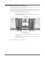
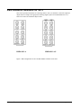
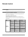
Cobalt Digital Inc. 9011 Standard Definition Digital to Analog Converter 10-bit SDI to Analog Composite, Y/C, RGB and Component Owner’s Manual 9011-OM Version: 1.2 9011 • Standard Definition D/A 10-bit SDI to Analog Composite, Y/C, RGB and Component Owner’s Manual • • • • • Cobalt Part Number: 9011-OM Document Version: 1.2 Printed in the United States. Last Author: CGG Printing Date: 2/11/2014 The information contained in this Owner’s Manual is subject to change without notice or obligation. Copyright © 2014 Cobalt Digital Inc. All rights reserved. Contents of this publication may not be reproduced in any form without the written permission of Cobalt Digital Inc. Reproduction or reverse engineering of copyrighted software is prohibited. Notice The material in this manual is furnished for informational use only. It is subject to change without notice and should not be construed as a commitment by Cobalt Digital Inc. Cobalt Digital Inc assumes no responsibility or liability for errors or inaccuracies that may appear in this manual. Trademarks • is a registered trademark of Ross Video Limited. • • is a registered trademark of Cobalt Digital Inc. All other product names and any registered and unregistered trademarks mentioned in this manual are used for identification purposes only and remain the exclusive property of their respective owners. 9011 Owner’s Manual • (V 1.2) Page 2 of 22 Important Regulatory and Safety Notices Before using this product and any associated equipment, refer to the “Important Safety Instructions” listed below so as to avoid personnel injury and to prevent product damage. Products may require specific equipment, and /or installation procedures be carried out to satisfy certain regulatory compliance requirements. Notices have been included in this publication to call attention to these specific requirements. Symbol Meanings This symbol on the equipment refers you to important operating and maintenance (servicing) instructions within the Product Manual Documentation. Failure to heed this information may present a major risk of damage or injury to persons or equipment. The symbol with the word “Warning” within the equipment manual indicates a potentially hazardous situation, which if not avoided, could result in death or serious injury. Warning The symbol with the word “Caution” within the equipment manual indicates a potentially hazardous situation, which if not avoided, may result in minor or moderate injury. It may also be used to alert against unsafe practices. Caution The symbol with the word “Notice” within the equipment manual indicates a situation, which if not avoided, may result in major or minor equipment damage or a situation which could place the equipment in a non-compliant operating state. Notice This symbol is used to alert the user that an electrical or electronic device or assembly is susceptible to damage from an ESD event. ESD Susceptibility Important Safety Instructions Caution This product is intended to be a component product of the openGearTM frame. Refer to the openGearTM frame Owner’s Manual for important safety instructions regarding the proper installation and safe operation of the frame as well as it’s component products. Warning Certain parts of this equipment namely the power supply area still present a safety hazard, with the power switch in the OFF position. To avoid electrical shock, disconnect all A/C power cords from the chassis' rear appliance connectors before servicing this area. Warning Service barriers within this product are intended to protect the operator and service personnel from hazardous voltages. For continued safety, replace all barriers after any servicing. This product contains safety critical parts, which if incorrectly replaced may present a risk of fire or electrical shock. Components contained within the product’s power supplies and power supply area, are not intended to be customer serviced and should be returned to the factory for repair. To reduce the risk of fire, replacement fuses must be the same type and rating. Only use attachments/accessories specified by the manufacturer. 9011 Owner’s Manual • (V 1.2) Page 3 of 22 Environmental Information The equipment that you purchased required the extraction and use of natural resources for its production. It may contain hazardous substances that could impact health and the environment. To avoid the potential release of those substances into the environment and to diminish the need for the extraction of natural resources, Cobalt Digital encourages you to use the appropriate take-back systems. These systems will reuse or recycle most of the materials from your end-of-life equipment in an environmentally friendly and health conscious manner. The crossed-out wheeled bin symbol invites you to use these systems. If you need more information on the collection, reuse, and recycling systems, please contact your local or regional waste administration. You can also contact Cobalt Digital for more information on the environmental performances of our products. 9011 Owner’s Manual • (V 1.2) Page 4 of 22 Contents Introduction 6 In This Chapter .......................................................................................................................... 6 A Word of Thanks ..................................................................................................................... 6 Overview.................................................................................................................................... 6 Features...................................................................................................................................... 7 Color Framing ............................................................................................................. 7 Software Version ....................................................................................................................... 7 Functional Block Diagram ......................................................................................................... 8 Supported Audio and Video Formats......................................................................................... 8 Input and Output Video ............................................................................................... 8 Documentation Terms................................................................................................................ 9 Installation and Setup 10 In This Chapter ........................................................................................................................ 10 Static Discharge ....................................................................................................................... 10 Unpacking................................................................................................................................ 10 Rear Module Installation (Optional) ........................................................................................ 11 Rear Module Available for 9011 ............................................................................................. 12 Board Installation..................................................................................................................... 13 Card Control and Status ........................................................................................................... 14 Card Control Switches............................................................................................... 14 Card Status LEDs ...................................................................................................... 15 Reference Configuration and Termination ................................................................ 15 Factory Default Settings ............................................................................................ 15 Remote Control 16 In This Chapter ........................................................................................................................ 16 DashBoard Control System Software ...................................................................................... 16 Technical Specifications 17 Service Information 18 In This Chapter ........................................................................................................................ 18 Troubleshooting Checklist ....................................................................................................... 18 Warranty and Repair Policy..................................................................................................... 19 Ordering Information 21 9011 and Related Products ...................................................................................................... 21 Contact Us 22 Contact Cobalt Digital Inc. ...................................................................................................... 22 Visit us at the Cobalt Digital Inc. website................................................................................ 22 9011 Owner’s Manual • (V 1.2) Page 5 of 22 Introduction In This Chapter This chapter includes the following sections: • A Word of Thanks • Overview • Functional Block Diagram • Supported Video Formats • Documentation Terms A Word of Thanks Congratulations on choosing the 9011 Standard Definition D/A 10-bit SDI to Analog Composite, Y/C, RGB and Component. The 9011 is part of a full line of modular conversion gear for broadcast TV environments. The Cobalt Digital openGearTM line includes video decoders and encoders, audio embedders and de-embedders, distribution amplifiers, format converters, and much more. Cobalt openGearTM modular conversion gear will meet your signal conversion needs now and well into the future. Should you have questions pertaining to the installation or operation of your 9011, please contact us at the numbers listed on the back cover of this manual. We are happy to help with any questions regarding this or any other openGearTM card. Overview The 9011is a high quality standard definition digital to analog converter for converting 525/625 4:2:2 SDI signals to analog Composite, Y/C and Component signals (YPbPr or RGB). The 9011 autodetects the line input standard and outputs the corresponding NTSC or PAL standard. The user can configure the default PAL outputs to be PAL-B/D/G/H/I, PAL N or PAL 60 and NSTC M or N. Pedestal selection can be enabled or disabled for NTSC operation. The 9011 can be externally configured to three different analog output configurations: all Composite, dual Composite with Y/C or Composite with Component. The 9011 supports four different Component output modes: BetaCam™, MII™, SMPTE/N10 and RGB. The encoding process is 10-bit with sample up-conversion from 4:2:2 to 8:8:8 (2x output mode) or 16:16:16 (4x output mode). Full user digital processing (proc.) controls are available to the end user for adjusting black level, Y Gain, Saturation and Hue. Advanced controls include VBI Blanking, line by line VBI Pedestal control, 9011 Owner’s Manual • (V 2.1) Page 6 of 32 extended filtering, DNR and Gamma configuration. All adjustments can be saved to non-volatile memory or Factory defaults can be restored. A De-jitter VCXO is included to reduce input jitter from high frequencies down to 2Hz. The 9011 has four reclocked digital output copies of the input SDI signal or three when the Genlock input is used, and one BNC reserved for Black Burst input. The user must adjust the SDI source’s HPhase for horizontal sync alignment. A full 360 degrees of SCH phase is user adjustable on the 9011. The input and outputs of the 9011 are the following: Inputs: One 10-bit SD-SDI video input One black burst reference input for color framing purposes Outputs: Four reclocked SD-SDI video outputs Four analog SD video outputs Features Color Framing Although an SD-SDI signal carries more information than a composite signal, it does not properly encode the SCH (Sub-Carrier to Horizontal) phase of the original composite signal. SCH phase is a measure of the relationship of the start of the color burst to the start of the horizontal sync. In NTSC each field has an SCH phase of 90° more than the previous field, thus the SCH sequence repeats every four fields. Since each SDI field encodes the field type (odd or even) but not the SCH phase, a given video encoder cannot recreate the SCH phase without a reference signal. This creates problems when trying to align the signals to the inputs of certain switching device that rely on the color phase being unified across channels. The 9011 circumvents this problem by accepting reference on either of the two frame inputs, or on a dedicated BNC on the rear IO module (rear module RM20-9011-A only). When reference is detected, the card will automatically ensure that the SCH phase of the output matches that of the reference signal. The reference must be synchronous with the input video for this to work, due to the nature of the comparison. There is a control to adjust the offset between output SCH phase and detected reference SCH phase. It is not needed in most applications. Software Version This manual is written for software release number 1.2. To view the current software release number of your 9011 check the card info menu in Dashboard. To upgrade your 9011 software, go to the download page at www.cobaltdigital.com to download the latest release, and upload the file through Dashboard™ (see Dashboard™ user manual, 3-5). 9011 Owner’s Manual • (V 1.2) Page 7 of 22 Functional Block Diagram This section diagrams the basic signal flow of your 9011 product. SDI Input SDI Output Frame Ref or BNC 2 Ref SDI Input Processing De-jitter SDI DA Microprocessor SW Ref GL 10 bit Encoding,Dig. Proc., Gamma Cntl., DNR, Filtering, 8:8:8 or 16:16:16 Output Filter, Mux Output Amps Config & Proc SW Analog Outputs Config. as: 4 Composite 2 Composite & Y/C 2 Y/C 1 Composite & Component 9011 Block Diagram Figure 1. Simplified Block Diagram of 9011 Functions Supported Audio and Video Formats Input and Output Video The 9011 supports both NTSC and PAL formats. Raster structure 486i1 575i1 Frame Rate 29.97 25 Notes: 1. All rates displayed as frame rates, interlaced (“i”) field rates are two times the number shown. 9011 Owner’s Manual • (V 1.2) Page 8 of 22 Documentation Terms The following terms are used throughout this guide: • “Frame” refers to the HPF-9000 or similar 20-slot frame that houses the 9011 card. • “Operator” and “User” both refer to the person who uses the 9011. • “Board” and “Card” all refer to the 9011 card itself, including all components and switches. • “System” and “Video system” refers to the mix of interconnected production and terminal equipment in which the 9011 operates. 9011 Owner’s Manual • (V 1.2) Page 9 of 22 Installation and Setup In This Chapter This chapter includes the following sections: • Static Discharge • Unpacking • Rear Module Installation (Optional) • Board Installation • BNC Connections • Menu Structure • Factory Defaults Static Discharge Whenever handling the card and other related equipment, please observe all static discharge precautions as described in the following note: Static discharge can cause serious damage to sensitive semiconductor devices. Avoid handling circuit boards in high static environments such as carpeted areas, and when wearing synthetic fiber clothing. Always exercise proper grounding precautions when working on circuit boards and related equipment. ESD Susceptibility Unpacking Unpack each card you received from the shipping container, and check the contents against the packing list to ensure that all items are included. If any items are missing or damaged, contact your sales representative or Cobalt Digital directly. 9011 Owner’s Manual • (V 1.2) Page 10 of 22 Rear Module Installation (Optional) If you are installing the card in a 8310-C-BNC or 8310-BNC frame (one with a 100 BNC rear module installed across the entire back plane), skip this section. If you are installing the card into a slot with no rear module, you should have ordered and received an appropriate 9011 rear module. You will need to install it in your frame before you can connect cables. Use the following steps to install a rear module in a frame: 1. On the rear of the frame, locate the card frame slot. 2. As shown in Figure 2, seat the bottom of the rear module in the seating slot at the base of the frame’s back plane. Figure 2. Rear Module Installation 3. Align the top hole of the rear module with the screw hole on the top edge of the frame back plane. 4. Using a Phillips driver and the supplied screw, fasten the rear module to the frame back plane. Do not over tighten. All modules are installed using the same method above. 9011 Owner’s Manual • (V 1.2) Page 11 of 22 Rear Modules Available for 9011 This section provides instructions for connecting cables to 9011 rear modules. Connect the input and output cables according to the appropriate following diagram. Split rear module RM20-9011-A/S allows two cards to be installed in adjacent slots. RM20-9011-A RM20-9011-A/S Figure 3. BNC Designations for the Card Rear Module available for the 9011. 9011 Owner’s Manual • (V 1.2) Page 12 of 22 Board Installation Use the following steps to install the card in the frame: 1. Warning Refer to the frame product manual to ensure that the frame is properly installed according to instructions. Heat and power distribution requirements within a frame may dictate specific slot placement of cards. Cards with many heat-producing components should be arranged to avoid areas of excess heat build-up, particularly in frames using convection cooling. 2. After selecting the desired frame installation slot, hold the card by the edges and carefully align the card edges with the slots in the frame. Then, fully insert the card into the frame until the rear connection plugs are properly seated on the midplane and rear modules. 3. Connect the input and output cables according to the diagram for the rear module being used. The inputs are internally terminated with 75 Ohms. It is not necessary to terminate unused outputs. This completes the procedure for installing the card in the frame. 9011 Owner’s Manual • (V 1.2) Page 13 of 22 Card Control and Status Card Control Switches The majority of the card control can be performed by the 8 switches on switch bank S1. Their operation is detailed in the following table. S1.2 ON* ON ON OFF OFF OFF OFF S1.4 ON* OFF S1.5 ON OFF* S1.6 ON* OFF S1.7 ON* OFF S1.8 ON* OFF S1.2 ON* OFF OFF ON ON OFF OFF S1.3 ON* ON OFF ON OFF ON OFF VIDEO INPUT AND COLOR SEPARATION MODE All Composite BNC 7 – Y, BNC 8 – C, BNC 9 – Composite, BNC 10 – Composite BNC 7 – Y, BNC 8 – C, BNC 9 – Y, BNC 10 – C BETACAM™ BNC 7 – Y, BNC 8 – Pr, BNC 9 – Pb, BNC 10 – Composite MII™ BNC 7 – Y, BNC 8 – Pr, BNC 9 – Pb, BNC 10 – Composite SMPTE BNC 7 – Y, BNC 8 – Pr, BNC 9 – Pb, BNC 10 – Composite RGB BNC 7 – Y, BNC 8 – Pr, BNC 9 – Pb, BNC 10 – Composite OUTPUT COLOR ENABLE Enable color on output Disable color on output OUTPUT TEST PATTERN Enable 75% color bars as output pattern, regardless of input signal Disable output test pattern ENABLE SETUP/PEDESTAL ON NTSC OUTPUT Output signal with 7.5 IRE setup/pedestal Output signal with 0 IRE of pedestal ENABLE OUTPUT OVERSAMPLING Output DAC runs at 2x SDI Y channel data rate (8:8:8 sampling) Output DAC runs at 4x SDI Y channel data rate (16:16:16 sampling) ENABLE OUTPUT DEJITTER FILTER DAC clock de-jitter filter enabled DAC clock de-jitter filter disabled Other, less used, parameters are adjusted by dialing S3 and S4 to certain values, and then moving the thumb switch S2 up or down. These parameters are detailed in the following table. For any given parameters, pressing the REGISTER RESTORE button (S5) will restore the parameter to it’s saved setting. S3 0 1 1 1 1 1 1 2 5 5 5 5 5 8 9 S4 0 1 2 3 4 5 6 7 0 1 2 3 4 8 9 Internal Parameter Normal card operation Y Gain Y Offset (Black level) Color Saturation Hue (for Composite and Y/C outputs only) +/-22.5º in 0.18º increments SCH Phase Sharpness –4dB to +4dB in 12 steps VBI lines 10-20 Encoded (LED On = Encoded, Off = VBI Blanked) Add setup/pedestal to odd lines 10-18 (NTSC only) Add setup/pedestal to odd lines 19-25 (NTSC only) Add setup/pedestal to even lines 10-18 (NTSC only) Add setup/pedestal to even lines 19-25 (NTSC only) Add setup/pedestal to all lines 10-25 (Note: overwrites settings of 5-0 through 5-3) Restore Factory Defaults (Press S2 Up) Save Settings (Press S2 Up) 9011 Owner’s Manual • (V 1.2) Page 14 of 22 Card Status LEDs The card LEDs report the lock status of the device. See the table below for an explanation of each function. LED NAME LOCK LED NTSC LED PAL LED RMT LED DESCRIPTION Flashes green when not locked to input signal. When locked illuminates steady green. When S3 or S4 not at 0, indicates state of parameter. On when locked to NTSC input, off otherwise On when locked to PAL input, off otherwise reserved for future use Reference Configuration and Termination The 9011 can use either a reference connected to the openGear™ frame, or a reference connected directly to BNC 2 to align the SCH phase of the output video. To use BNC 2 as the reference, set S12 to BNC2. To use the openGear™ frame’s reference, set S12 to FRAME and then select which of the two frame references to be used using S11. It is important to note that the 9011 does not operate as a frame synchronizer. The output video timing will always match the SDI input timing. Factory Default Settings The factory default settings are as follows 1) S1.2-3 Output is composite on all ports 2) S1.4 - Color is On 3) S1.5 – Test Pattern is Off 4) S1.6 – Setup is On 5) S1.7 – Output Sample Mode is 16:16:16 6) S1.8 – De-Jitter Filter is On 9011 Owner’s Manual • (V 1.2) Page 15 of 22 Remote Control In This Chapter This section provides a detailed explanation on using remote control functions with your card. DashBoard Control System Software The DashBoard Control System enables you to monitor and control openGearTM frames and controller cards from a computer. The DashBoard software and manual can be downloaded from the Cobalt Digital Inc. website (www.cobaltdigital.com). Using the Menus and Menu Descriptions You must first install the DashBoard Control System software on your computer. Refer to the DashBoard User Manual for software installation procedures and for using the DashBoard interface. The following pages list the parameters from the menu tabs available in the DashBoard software when connected to a 9011. Menu Item Format Description Product CDI-9011 The product name Cobalt Digital Inc. The manufacturer of the product Manufacturer Card Info (Read-only) 9011 Owner’s Manual • (V 1.2) Serial Number ############ The product serial number Software Release Number ### The release number of the firmware in this card PIC Software Build Number ## The internal build number of this software Degrees C / Degrees F The surface temp of the board +12 V Power Rail #.## W Positive Supply Power -7.5 Power Rail #.## W Negative Supply Power Power #.# W Total power consumed by the board Input Signal ############ Detected standard of the input signal. Temperature Page 16 of 22 Technical Specifications Table 4. Card - Technical Specifications Category Parameter Serial Digital Video Input Analog Video Output Reference Video Input Other Specification Data Rates Supported SMPTE 259M-C SD-SDI: 270 Mbps Frame Rates Supported 486i 29.97 NTSC, 575i 25 PAL Impedance 75Ω terminating Equalization 1000ft (300 meters) Belden 1694A Return Loss >18dB at 5MHz – 270MHz Number of Outputs 4 Video Outputs Composite, Component YPbPr (BetaCam™, MII™, SMPTE/N10), RGB, and Y/C Conversion Bit Depth 10-Bits Frequency Response 4x Y: 0-5.5 MHz +/- 0.15 dB 4x PbPr: 0-2.2 MHz +/-0.25 dB Differential Phase < ±0.5° typical Differential Gain < ±0.5% typical S/N > 75 dB Conversion Time < 2 us K-Factor 2T < 0.6% SCH Phase < 0.8% Return Loss > 35dB to 5 MHz Number of Inputs 1 1 Standards Supported 486i 29.97 NTSC, 575i 25 PAL Signal Level 1Vp-p nominal Signal Analog video sync (black burst or tri-level) Impedance 75Ω Return Loss > 30dB to 30MHz Max DC on Ref Input ±1V Total Power Consumption < 7W Warranty Five Year Transferable Terminating Frame Reference Inputs Terminating Reference on BNC 2 Specifications are subject to change without notice. 9011 Owner’s Manual • (V 1.2) Page 17 of 22 Service Information In This Chapter This chapter includes the following sections: • Troubleshooting Checklist • Warranty and Repair Policy Troubleshooting Checklist Routine maintenance to this openGearTM product is not required. In the event of problems with your card, the following basic troubleshooting checklist may help identify the source of the problem. If the module still does not appear to be working properly after checking all possible causes, please contact your openGearTM products distributor, or the Technical Support department at the numbers listed under the “Contact Us” section at the end of this manual. 1. Visual Review Performing a quick visual check may reveal many problems, such as connectors not properly seated or loose cables. Check the module, the frame, and any associated peripheral equipment for signs of trouble. 2. Power Check Check the power indicator LED on the distribution frame front panel for the presence of power. If the power LED is not illuminated, verify that the power cable is connected to a power source and that power is available at the power main. Confirm that the power supplies are fully seated in their slots. If the power LED is still not illuminated, replace the power supply with one that is verified to work. 3. Reseat the Card in the Frame Eject the card and reinsert it in the frame. 4. Check Control Settings Refer to the Installation and Operation sections of the manual and verify all user-adjustable component settings. 5. Input Signal Status Verify that source equipment is operating correctly and that a valid signal is being supplied. 6. Output Signal Path Verify that destination equipment is operating correctly and receiving a valid signal. 7. Module Exchange Exchanging a suspect module with a module that is known to be working correctly is an efficient method for localizing problems to individual modules. 9011 Owner’s Manual • (V 1.2) Page 18 of 22 Warranty and Repair Policy Cobalt Digital Inc. Limited Warranty This product is warranted to be free from defects in material and workmanship for a period of five (5) years from the date of shipment to the original purchaser, except that 4000, 5000, 6000, 8000 series power supplies, and Dolby® modules (where applicable) are warranted to be free from defects in material and workmanship for a period of one (1) year. Cobalt Digital Inc.'s (“Cobalt”) sole obligation under this warranty shall be limited to, at its option, (i) the repair or (ii) replacement of the product, and the determination of whether a defect is covered under this limited warranty shall be made at the sole discretion of Cobalt. This limited warranty applies only to the original end-purchaser of the product, and is not assignable or transferrable therefrom. This warranty is limited to defects in material and workmanship, and shall not apply to acts of God, accidents, or negligence on behalf of the purchaser, and shall be voided upon the misuse, abuse, alteration, or modification of the product. Only Cobalt authorized factory representatives are authorized to make repairs to the product, and any unauthorized attempt to repair this product shall immediately void the warranty. Please contact Cobalt Technical Support for more information. To facilitate the resolution of warranty related issues, Cobalt recommends registering the product by completing and returning a product registration form. In the event of a warrantable defect, the purchaser shall notify Cobalt with a description of the problem, and Cobalt shall provide the purchaser with a Return Material Authorization (“RMA”). For return, defective products should be double boxed, and sufficiently protected, in the original packaging, or equivalent, and shipped to the Cobalt Factory Service Center, postage prepaid and insured for the purchase price. The purchaser should include the RMA number, description of the problem encountered, date purchased, name of dealer purchased from, and serial number with the shipment. Cobalt Digital Inc. Factory Service Center 2406 E. University Avenue Office: (217) 344-1243 Urbana, IL 61802 USA Fax: www.cobaltdigital.com Email: [email protected] (217) 344-1245 THIS LIMITED WARRANTY IS EXPRESSLY IN LIEU OF ALL OTHER WARRANTIES EXPRESSED OR IMPLIED, INCLUDING THE WARRANTIES OF MERCHANTABILITY AND FITNESS FOR A PARTICULAR PURPOSE AND OF ALL OTHER OBLIGATIONS OR LIABILITIES ON COBALT'S PART. ANY SOFTWARE PROVIDED WITH, OR FOR USE WITH, THE PRODUCT IS PROVIDED “AS IS.” THE BUYER OF THE PRODUCT ACKNOWLEDGES THAT NO OTHER REPRESENTATIONS WERE MADE OR RELIED UPON WITH RESPECT TO THE QUALITY AND FUNCTION OF THE GOODS HEREIN SOLD. COBALT PRODUCTS ARE NOT AUTHORIZED FOR USE IN LIFE SUPPORT APPLICATIONS. COBALT'S LIABILITY, WHETHER IN CONTRACT, TORT, WARRANTY, OR OTHERWISE, IS LIMITED TO THE REPAIR OR REPLACEMENT, AT ITS OPTION, OF ANY DEFECTIVE PRODUCT, AND SHALL IN NO EVENT INCLUDE SPECIAL, INDIRECT, INCIDENTAL, OR CONSEQUENTIAL DAMAGES (INCLUDING LOST PROFITS), EVEN IF IT HAS BEEN ADVISED OF THE POSSIBILITY OF SUCH DAMAGES. 9011 Owner’s Manual • (V 1.2) Page 19 of 22 In Case of Problems Should any problem arise with your openGear® card, please contact the Cobalt Digital Inc. Technical Support Department. (Contact information is supplied at the end of this publication.) A Return Material Authorization number (RMA) will be issued to you, as well as specific shipping instructions, should you wish our factory to repair your openGear® card. If required, a temporary replacement module will be made available at a nominal charge. Any shipping costs incurred will be the responsibility of you, the customer. All products shipped to you from Cobalt Digital Inc. will be shipped collect. The Cobalt Digital Inc. Technical Support Department will continue to provide advice on any product manufactured by Cobalt Digital Inc., beyond the warranty period without charge, for the life of the equipment. 9011 Owner’s Manual • (V 1.2) Page 20 of 22 Ordering Information 9011 and Related Products Your 9011 Standard Definition D/A 10-bit SDI to Analog Composite, Y/C, RGB and Component is a part of the openGearTM family of products. Cobalt Digital offers a full line of openGearTM terminal equipment including distribution, conversion, monitoring, synchronizers, encoders, decoders, embedders, and de-embedders, as well as analog audio and video products. Standard Equipment • 9011 Standard Definition D/A 10-bit SDI to Analog Composite, Y/C, RGB and Component • 9011-OM Standard Definition D/A 10-bit SDI to Analog Composite, Y/C, RGB and Component Owner’s Manual Optional Equipment • 9011-OM Standard Definition D/A 10-bit SDI to Analog Composite, Y/C, RGB and Component Owner’s Manual (additional Owner’s Manual) RM20-9011-A 20-Slot Frame Rear I/O Module (Standard Width) SDI Input, 4 Reclocked SDI Outputs, 4 Analog Outputs (4x Composite or Component, Y/C) RM20-9011-A/S 20-Slot Frame Rear I/O Module (Split) SDI Input, 2 Reclocked SDI Outputs, 2 Analog Outputs (connectors are per card) • HPF-9000-CN High-Power 20-Slot Frame; 2RU with fans, cover plates for unused slots. Includes one PSU-9000 Power Supply Module and MFC-8320-N Network Controller Card. • OG3-FR 20-Slot Frame and Power Supply with Cooling Fans and Network Controller Card (2RU, holds 20 cards maximum) 9011 Owner’s Manual • (V 1.2) Page 21 of 22 Contact Us Contact Cobalt Digital Inc. PHONE E-MAIL POSTAL SERVICE General Business Office and Technical Support 217.344.1243 Fax 217.344.1245 General Information [email protected] Sales Information [email protected] Cobalt Digital Inc. 2406 East University Avenue Urbana, IL 61802 USA Visit us at the Cobalt Digital Inc. website. http://www.cobaltdigital.com • Online catalog • Related products and full product lines • Trade show information • Dealer information • Cobalt Digital Inc. news 9011 Owner’s Manual • (V 1.2) Page 22 of 22