1
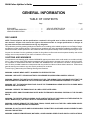
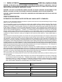
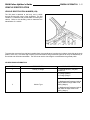
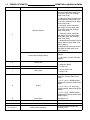
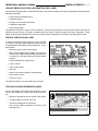
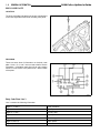
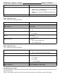
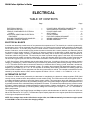
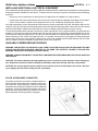
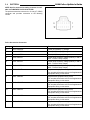
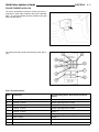
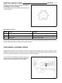
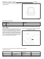
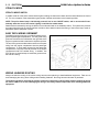
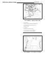
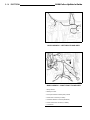
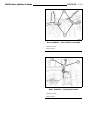
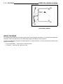
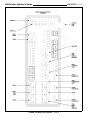
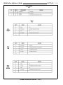
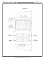
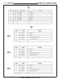
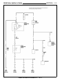
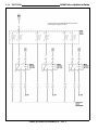
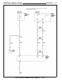
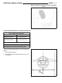
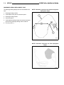
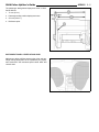
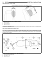
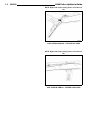
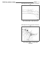
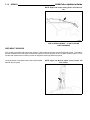
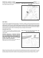
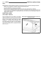
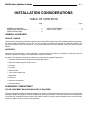
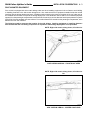
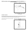
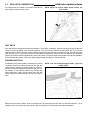
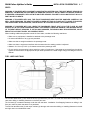
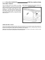
2008 Dodge Charger/Magnum
Police Upfitter's Guide
Table of Contents
INTRODUCTION
1
2
GENERAL INFORMATION
ELECTRICAL
3
4
AIRBAGS
INSTALLATION CONSIDERATIONS
2008 Police Upfitter’s Guide
0-1
INTRODUCTION
TABLE OF CONTENTS
Page
INTRODUCTION . . . . . . . . . . . . . . . . . .
1
INTRODUCTION
The Police Upfitter’s Guide has been prepared with the assistance of service and engineering specialists to assist vehicle
upfitters in achieving the highest standards of safety and quality in their products.
This guide is divided into topics pertinent to upfitters of police vehicles. References are made to the 2008 Dodge Charger
and Magnum Service Manual for appropriate service procedures, torques specifications, component separation clearances, and other standard information that is common with the unmodified vehicle.
The Police Upfitter’s Guide does not provide information on how to remove, install, or repair vehicle parts or equipment.
This guide must be used as a reference to help ensure that certain important steps in the modification process have
been considered. Chrysler LLC provides this information only to assist the upfitters, and does not warrant the products,
procedures, materials, or the workmanship of the upfitters. Chrysler LLC does not provide warranty coverage against
failures that result from modification of the vehicle.
Following the guidelines contained in this guide does not assure the individual upfitters that the products they modify
comply with the U.S. Federal or Canadian Motor Vehicle Safety Standards in effect at the time of the modification. The
guidelines set forth are based on engineering analyses of the typical police vehicles. If followed, the upfitter’s efforts in
certifying vehicles to applicable standards should be aided. Compliance testing that may be required for certification of
specific vehicle configurations or constructions is, however, the sole responsibility of the individual modifier.
2008 Police Upfitter’s Guide
1-1
GENERAL INFORMATION
TABLE OF CONTENTS
Page
DISCLAIMER . . . . . . . . . . . . . . . . . . . .
CAUTIONS AND WARNINGS . . . . . . . . . . .
VEHICLE MODIFICATION . . . . . . . . . . . . .
1
1
2
Page
VEHICLE IDENTIFICATION . . . . . . . . . . . .
NEW VEHICLE STORAGE . . . . . . . . . . . .
5
10
DISCLAIMER
NOTE: The descriptions and the specifications contained in this guide were in effect at the time this manual
was released. Chrysler LLC reserves the right to discontinue models or change specifications or designs at
any time without notice and without incurring any obligation.
This publication provides general guidelines and directions for installing police related equipment on the Dodge Charger
and Magnum police certified vehicles. Following these guidelines and using appropriate installation procedures is essential for the safe, reliable operation of the vehicles as well as the personal safety of the individual performing the work.
Anyone who deviates from the guidelines provided in this guide must first make sure that personal safety and vehicle
integrity are not compromised by his choice of methods, tools or parts.
CAUTIONS AND WARNINGS
It is important to note that this guide contains WARNINGS against procedures which could result in an accident or bodily
injury. It also contains CAUTIONS against procedures which could result in damage to the vehicle or render it unsafe.
It is important to understand that these CAUTIONS and WARNINGS are not exhaustive, because it is impossible to
warn of all the possible hazardous consequences that may result from failure to follow these instructions. Follow these
general warnings and cautions any time work is performed on a vehicle.
To avoid injury, please obey the following Warnings and Cautions:
WARNING: ALWAYS WEAR SAFETY GLASSES FOR EYE PROTECTION.
WARNING: USE SAFETY STANDS ANYTIME A PROCEDURE REQUIRES BEING UNDER A VEHICLE.
WARNING: REMOVE THE IGNITION OFF DRAW (IOD) FUSE, THE AIRBAG FUSES, AND MAKE SURE THAT THE
IGNITION SWITCH IS ALWAYS IN THE OFF POSITION, UNLESS THE PROCEDURE REQUIRES IT TO BE ON.
WARNING: SET THE PARKING BRAKE AND PLACE THE TRANSMISSION GEAR SELECTOR IN PARK WHEN
WORKING ON ANY VEHICLE.
WARNING: OPERATE THE ENGINE ONLY IN A WELL-VENTILATED AREA.
WARNING: KEEP AWAY FROM MOVING PARTS WHEN THE ENGINE IS RUNNING, ESPECIALLY THE FAN AND
BELTS.
WARNING: TO PREVENT SERIOUS BURNS, AVOID CONTACT WITH HOT PARTS SUCH AS THE RADIATOR, EXHAUST MANIFOLD(S), TAIL PIPE CATALYTIC CONVERTERS AND MUFFLERS.
WARNING: ALWAYS REMOVE THE FUEL TANK, DRAIN, PURGE, AND PLUG THE FUEL LINES WHEN UNDERBODY OR FLOOR PAN WELDING IS REQUIRED.
WARNING: DO NOT ALLOW FLAME OR SPARKS NEAR THE BATTERY. GASES ARE ALWAYS PRESENT IN AND
AROUND THE BATTERY.
WARNING: ALWAYS REMOVE RINGS, WATCHES, LOOSE HANGING JEWELRY AND AVOID LOOSE CLOTHING.
1-2
2008 Police Upfitter’s Guide
GENERAL INFORMATION
WARNING: AFTER INSTALLING ANY EQUIPMENT OR AFTER ANY OTHER WORK IS COMPLETED, TURN THE
IGNITION KEY TO THE ON POSITION AND MONITOR THE AIRBAG INDICATOR TO MAKE SURE THERE ARE NO
FAULTS IN THE SUPPLEMENTAL RESTRAINTS SYSTEM.
WARNING: USE ONLY THE APPROVED POWER, GROUND, OR SIGNAL SOURCES AS DESCRIBED IN THIS
MANUAL. SPLICING, CUTTING, OR ALTERING THE VEHICLE HARNESS CIRCUITS IS NOT PERMITTED.
WARNING: ALWAYS DISCONNECT THE BATTERY CABLE BEFORE PERFORMING ANY ELECTRICAL WORK ON
THE VEHICLE.
VEHICLE MODIFICATION
INFORMATION CONCERNING UNITED STATES AND CANADA SAFETY STANDARDS
Chrysler LLC has prepared the following information for persons who intend to modify the 2008 Dodge Charger or Dodge
Magnum police prep package vehicles.
The vehicle modifier or alterer is responsible for re-certifying the modified vehicle as altered pursuant to Title 49 of the
Code of Federal Regulations S567.7 and S568.6 in the United States or to Section 9 of the Canadian Motor Safety
Regulations in Canada. A vehicle modifier is a person or company who modifies a previously certified vehicle other than
by the addition, substitution or removal of readily attachable components. Upon completion of the modified vehicle, the
vehicle modifier is required by law to certify that it continues to comply with all applicable Federal and Canada Motor
Vehicle Safety Standards/Regulations. In addition, the modified vehicle must continue to comply with all applicable
Federal, Canada and/or California Emissions regulations. In the United States, sale of a non-complying new vehicle
is illegal and is punishable by a fine of up to $27,500 (Federal) and $5,000 (California) per vehicle for emissions noncompliance, $1,000 per vehicle for safety non-compliance, plus recall and other sanctions. Other penalties apply in
Canada.
This material is for informational purposes only and sets forth some general observation on this subject. Dealers and/or
vehicle modifiers should seek assistance from the legal counselor of their choice to aid them in understanding their specific obligations. Specific questions concerning compliance and/or certification to safety standards and emissions and
related (e.g. fuel economy) regulations should be directed to the vehicle modifiers legal counsel or the United States National Highway Traffic Safety Administration (Federal Motor Vehicle Safety Standards and Federal Economy Standards
and Requirements), the Canada Department of Transport/Transport Canada (Canada Motor Vehicle Safety/Regulations,
including emissions and noise regulations), Industry Canada (Interference-Causing Equipment Standards), the United
States Environmental Protection Agency (United States emissions and fuel vapor requirements) or The California Air
Resources Board (California emissions and fuel vapor requirements).
Chrysler LLC makes no representations with regard to conformity of the modified vehicle to any Federal or Canadian
Motor Vehicle Safety Standards/Regulations that may be affected by the vehicle modification; it is the responsibility of
the vehicle modifier to certify that the vehicle conforms to any standards affected by the vehicle modification. Additional
information concerning United States Federal Motor Vehicle Safety Standards and Canada Motor Vehicle Safety Regulations is provided in the current 2008 Dodge Truck Body Builder’s Guide CD-ROM.
The vehicles listed in the following table will conform to the safety standards noted above provided the following conditions are satisfied:
• The altered vehicle’s unloaded vehicle weight does not exceed the value designated in the table corresponding
to the vehicle’s model and engine size. “Unloaded vehicle weight”, as defined in the Title 49 Code of Federal
Regulations, Part 571.3, means “the weight of a vehicle with maximum capacity of all fluids necessary for operation
of the vehicle, but without cargo or occupants”, and following alteration it still conforms to all applicable Federal
Motor Vehicle Safety Standards (or Canadian Motor Vehicle Safety Standards).
Engine Size (Liters)
Maximum Unloaded Vehicle Weight (Pounds) w/Max
Options
Dodge Charger
3.5
3966
5.7
4181
3.5
4044
5.7
4257
Dodge Magnum
2008 Police Upfitter’s Guide
GENERAL INFORMATION
1-3
SAFETY DEVICES
The Dodge Charger and Magnum are factory equipped with many safety devices and features required by the Federal
Motor Vehicle Safety Standards (FMVSS) or the Canada Motor Vehicles Safety Regulations. These features, which
include for example brakes, lights, tires, seat belts, airbags, the key-in-ignition chime, the brake lights, etc., should not
be modified or disabled.
The United States Code (USC), Section 30122 Making Safety Devices and Elements Inoperative, states that “A manufacturer, distributor, dealer, or motor vehicle repair business may not knowingly make inoperative any part of a device or
element of design installed on or in a motor vehicle or motor vehicle equipment in compliance with an applicable motor
vehicle safety standard prescribed under this chapter unless the manufacturer, distributor, dealer, or repair business reasonably believes the vehicle or equipment will not be used (except for testing or a similar purpose during maintenance
or repair) when the device or element is inoperative.”
VEHICLE DIMENSIONS
The Dodge Charger vehicles have the following overall exterior dimensions:
•
•
•
•
•
•
Length (A) = 5,082 mm (200.1 in.)
Front overhang (B) = 924 mm (36.4 in.)
Wheelbase (C) = 3,048 mm (120.0 in.)
Rear overhang (D) = 1,109 mm (43.7 in.)
Height (E) = 1,479 mm (58.2 in.)
Width (F) = 1,891 mm (74.5 in.)
1-4
2008 Police Upfitter’s Guide
GENERAL INFORMATION
The Dodge Magnum vehicles have the following overall exterior dimensions:
•
•
•
•
•
•
Length (A) = 5,021 mm (197.7 in.)
Front overhang (B) = 886 mm (34.9 in.)
Wheelbase (C) = 3,048 mm (120.0 in.)
Rear overhang (D) = 1,087 mm (42.8 in.)
Height (E) = 1,481 mm (58.3 in.)
Width (F) = 1,881 mm (74.1 in.)
BUMPER HEIGHTS
Every time a vehicle is modified, measure the front and rear bumper heights to verify compliance with the FMVSS/CMVSS
Part 581 - Bumper Standard, and with the Chrysler LLC specifications. Take bumper height measurements with the vehicle at curb weight.
Measure the bumper heights as follows:
NOTE: Take the measurements from the bottom of the bumper structural beam, not from the bumper fascia
surface.
•
•
•
•
Place the vehicle on a flat, level surface.
Place the transmission gear selector lever in the PARK position.
Exit the vehicle.
At the center of the bumper, measure the vertical distance from the floor surface to the bottom of the front bumper
structural beam.
• At the center of the bumper, measure the vertical distance from the floor surface to the bottom of the rear bumper
structural beam.
• Record and compare the measurements with the specifications below.
Front bumper height
393.4 ±12.5 mm (15.5 ±0.5 inches)
Rear bumper height
367.6 ±12.5 mm (14.5 ±0.5 inches)
2008 Police Upfitter’s Guide
GENERAL INFORMATION
1-5
VEHICLE IDENTIFICATION
VEHICLE IDENTIFICATION NUMBER (VIN)
The VIN plate is attached to the body, and is visible
through the lower left corner of the windshield. The VIN
contains 17 characters that provide data concerning the
vehicle. Refer to the decoding chart to determine the
identification of a vehicle.
To protect the consumer from theft and possible fraud, the manufacturer is required to include a check digit at the ninth
position of the VIN. The check digit is used by the manufacturer and government agencies to verify the authenticity of
the vehicle and official documentation. The formula to use the check digit is not released to the general public.
VIN DECODING INFORMATION
POSITION
INTERPRETATION
1
Country of Origin
CODE = DESCRIPTION
2 = Manufactured by Chrysler
Canada Inc.
B = Dodge (Sedan)
D = Dodge (Wagon
3 = Passenger Car
3
Vehicle Type
4 = Multipurpose Passenger Vehicle
Without Side Air Bags Sales Code
(CGS) (Wagon)
8 = Multipurpose Passenger Vehicle
With Side Air Bags Sales Code
(CGS) (Wagon)
1-6
2008 Police Upfitter’s Guide
GENERAL INFORMATION
POSITION
INTERPRETATION
CODE = DESCRIPTION
H = Restraint System Air bags Front
Next Generation Multi-Stage Sales
Code (CG1) With Side Air Bags
Sales Code (CGS)
J = Restraint System Air Bags Front
Next Generation Multi-Stage Sales
Code (CG1) Without Side Air Bags
Sales Code (CGS)
Restraint System
K = Restraint System Advanced
Multi-Stage Front Air Bags Sales
Code (CG3) With Side Air Bags
Sales Code (CGS)
L = Restraint System Advanced
Multi-Stage Front Air Bags Sales
Code (CG3) With Side Air Bags
Sales Code (CGS)
4
4 = Multipurpose Passenger Vehicle
Without Side Air Bags Sales Code
(CGS) (Wagon)
8= Multipurpose Passenger Vehicle
With Side Air Bags Sales Code
(CGS) (Wagon)
Gross Vehicle Weight Rating
5
Vehicle Line
6
Series
7
Body Style
E = 1361-1814 kg (3001-4000 lbs)
(Wagon)
F = 1815-2267 kg (4001-5000 lbs)
(Wagon)
A = Charger (RWD)
V = Magnum (RWD)
4 - H High Line
3 = 4 Door Sedan Tall
7 = Wagon Tall
G = 3.5L V-6 cyl. High Output 24
Valve MPI Gasoline Sales Code
(EGG)
8
Engine
H = 5.7L V-8 cyl. HEMI® Multiple
Displacement Gasoline Sales Code
(EZB)
V = 3.5L V-6 cyl. 24 Valve High
Output Gasoline, Sales Code (EZB)
(Wagon)
2 = 5.7L V-8 cyl. HEMI® Multiple
Displacement Gasoline Sales Code
(EZB) (Wagon)
9
Check Digit
0 through 9 or X
10
Model Year
8 = 2008
11
Assembly Plant
12 Through 17
Vehicle Build Sequence
H = Brampton Assembly
Six Digit Number Assigned By
Assembly Plant
2008 Police Upfitter’s Guide
GENERAL INFORMATION
1-7
VEHICLE EMISSION CONTROL INFORMATION (VECI) LABEL
All vehicles are equipped with a combined VECI label. This label is located in the engine compartment and contains the
following information.
•
•
•
•
•
Engine family and displacement
Evaporative family
Emission control system schematic
Certification application
Spark plug and gap
The label also contains an engine vacuum schematic. There are unique labels for vehicles built for sale in the state of
California and the country of Canada. Canadian labels are written in both the English and French languages. These
labels are permanently attached and cannot be removed without defacing the information and destroying the label.
VEHICLE CERTIFICATION LABEL
A vehicle certification label is attached to every Chrysler
LLC vehicle. The label certifies that the vehicle conforms
to all applicable Federal Motor Vehicle Standards. The label also lists:
• Month and year of vehicle manufacture
• Gross vehicle weight rating (GVWR). The gross front
and rear axle weight ratings (GAWRs) are based on
a minimum rim size and maximum cold tire inflation
pressure.
•
•
•
•
•
•
•
Vehicle identification number (VIN)
Type of vehicle
Type of rear wheels
Bar code
Month, day and hour (MDH) of final assembly
Paint and trim codes
Country of origin
The label is located on the driver-side door shut-face.
TIRE AND LOADING INFORMATION LABEL
The tire and loading information label is located on the
driver’s side B-pillar and contains the following information:
•
•
•
•
Number of people that can be carried in the vehicle.
The total weight the vehicle can carry.
The tire size designed for the vehicle.
The cold tire inflation pressures for the front, rear,
and spare tires.
1-8
2008 Police Upfitter’s Guide
GENERAL INFORMATION
BODY CODE PLATE
LOCATION
The body code plate is located in the engine compartment
on the front right side shock tower mounting front panel.
DECODING
There are seven lines of information on the body code
plate. Lines 4, 5, 6, and 7 are not used to define service
information. Information reads from left to right, starting
with line 3 in the center of the plate to line 1 at the bottom
of the plate.
Body Code Plate Line 3
Line 3 contains the following information.
Digits 1, 2, and 3
Paint procedure
Digit 4
Open space
Digits 5, 6, and 7
Primary paint
Digits 8 and 9
Open space
Digits 10, 11, and 12
Secondary paint
Digits 13 and 14
Open space
Digits 15, 16, 17, and 18
Interior trim code
2008 Police Upfitter’s Guide
GENERAL INFORMATION
Digit 19
Open space
Digits 20, 21, and 22
Engine code
1-9
• EGG = 3.5 L, V-6 Cylinder, 24 Valve, High Output,
Gasoline, Aluminum Block (MPI)
• EZB = 5.7 L, V-8 Cylinder, HEMI®, Multi-Displacement,
Gasoline,
Digit 23
Open space
Body Code Plate Line 2
Line 2 contains the following information.
Digits 1 through 12
Vehicle order number
Digits 13, 14, and 15
Vinyl roof code
Digits 16 and 17
Open space
Digits 18 and 19
Vehicle shell line
• LX
Digit 20
Car line
• D = Dodge
Digit 21
Price class
• H = High Line
Digits 22 and 23
Body type
• 48 = Four Door Sedan Tall
• 49 = Hatchback Tall
Body Code Plate Line 1
Line 1 contains the following information.
Digits 1, 2, and 3
Transmission codes
• DGK = 5-Speed Automatic Transmission
Digit 4
Open space
Digit 5
Market code
• C = Canada
• M = Mexico
• U = United States
Digit 6
Open space
Digits 7 through 23
Vehicle identification number (VIN)
Second Body Code Plate
The last code shown on either plate is followed by END. When two plates are required, the last code space on the first
plate indicates CTD.
When a second plate is required, the first four spaces of each line are not used due to overlap of the plates.
1 - 10
GENERAL INFORMATION
2008 Police Upfitter’s Guide
MANUFACTURER PLATE
The manufacturer plate is located in the engine compartment on the passenger side rear corner of the hood. The
plate contains five lines of information:
•
•
•
•
•
Vehicle identification number (VIN)
Gross vehicle mass (GVM)
Gross train mass (GTM)
Gross front axle rating (GFAR)
Gross rear axle rating (GRAR)
NEW VEHICLE STORAGE
If a vehicle is not immediately delivered to the customer, store the vehicle according to the following guidelines:
1. If possible, store the vehicle indoors, in a clean and dry place. If vehicles must be stored outside;
• Avoid storage locations near obvious sources of industrial or environmental contamination (such as, trees, factories, steam or vapor vents, railroad tracks, etc.)
• Maintain tight security to help prevent vandalism. Inspect the vehicle regularly to check for such damage.
• If the vehicle must be parked on an incline, park it with the front end higher than the rear. This prevents hydrostatic
lock caused by fuel draining into the engine.
• Rinse the vehicle at least once a week. Wash away the snow more often since it can trap harmful contaminants.
Dry all horizontal surfaces.
2. Remove the IOD fuse to prevent battery drain and possible damage.
3. Check the engine coolant and anti-freeze protection.
WARNING: THE BATTERY IN THIS VEHICLE HAS A VENT HOSE THAT SHOULD NOT BE DISCONNECTED
AND SHOULD ONLY BE REPLACED WITH A BATTERY OF THE SAME TYPE (VENTED). FAILURE TO FOLLOW THIS WARNING CAN RESULT IN SERIOUS OR FATAL INJURY.
4. Check the vehicle battery at least once a month for proper charge (at least 12.4 volts). Charge the battery as necessary to help prevent freezing and deterioration. Always make sure that the battery vent tube is properly connected
to the battery and to the floor pan.
5. Check the vehicle tires and inflate them to the maximum recommended levels. To avoid flat spotting, move the
vehicle at least once a month so that a different portion of the tire tread contacts the ground.
6. Leave the parking brake in the OFF position.
7. Keep all windows closed, all doors locked, and all trim covers intact and in place.
8. Do not use chalk, crayon or any marker containing abrasives on painted, plated, or glass surfaces.
9. Use protective thin plastic film to avoid soiling seats when moving a vehicle.
2008 Police Upfitter’s Guide
2-1
ELECTRICAL
TABLE OF CONTENTS
Page
ELECTRICAL BASICS . . . . . . . . . . . .
ALTERNATOR OUTPUT . . . . . . . . . . .
VEHICLE COMPONENTS ELECTRICAL
LOADS . . . . . . . . . . . . . . . . . . .
INSTALLING ADDITIONAL ELECTRICAL
EQUIPMENT . . . . . . . . . . . . . . . .
AVAILABLE POWER/GROUND SOURCES
AVAILABLE VEHICLE SIGNALS . . . . . .
. . .
. . .
1
1
. . .
2
. . .
. . .
. . .
3
3
6
Page
POLICE RADIO SPEAKERS CONNECTION.
SUPPLEMENTAL EQUIPMENT WIRING . . .
POLICE DOME LAMP . . . . . . . . . . . . .
SPOT LAMPS . . . . . . . . . . . . . . . . . .
STEALTH MODE . . . . . . . . . . . . . . . .
EASY PATH WIRING GROMMET . . . . . . .
WIRING HARNESS ROUTING . . . . . . . .
WIRING DIAGRAMS . . . . . . . . . . . . . .
.
.
.
.
.
.
.
.
.
.
.
.
.
.
.
.
8
9
10
11
12
12
12
16
ELECTRICAL BASICS
A vehicle uses electricity to make some of its systems and components work. The electricity in a vehicle is produced by
the alternator, which can be compared with a water pump. As a water pump moves the water molecules, the alternator
moves the electrons. As a water pump pushes a certain amount of water molecules, the alternator pushes a certain
amount of electrons, and as a water pump pushes the water molecules with a certain pressure, the alternator pushes
the electrons with a certain pressure. The amount of electrons pushed by the alternator is called amperage, and the
“pressure” is called voltage. Electricity is distributed to the battery and to various components through a network of
conductors called a wiring harness. The same way the water is pushed through pipes, is the same way the electrons
are pushed through metallic conductors called wires. As the pipe diameter limits the number of water molecules that
can travel at any given point, the size of the wire limits the amount of the electrons that can travel at any given point.
In 1827 Georg Simon Ohm published what is called today Ohm’s law. According to Ohm’s law, the relation between
voltage (V), amperage (I), and the resistance (R) encountered by the electricity while traveling through conductors is V
= I x R. The rate at which a device converts the electricity to a different form of energy (visual, acoustical, mechanical,
or hydraulic) is called power, and is measured in watts. An equation that expresses the relationship between volts (V),
amperes (A), and watts (W), is V x A = W. This equation is necessary when making calculations for making proper and
safe electrical installation of new equipment and new wiring harnesses in a vehicle. For example to calculate the current
needed by an amplifier rated at 120W, use the equation as follows: 12V x A = 120W, => A = 120W/12V, => A = 10.
ALTERNATOR OUTPUT
The amount of direct current produced by the alternator is controlled by the electronic voltage regulator (EVR) (field
control) circuitry contained within the powertrain control module (PCM). The PCM uses the inlet air temperature sensor
or ambient temperature sensor to control the charge system voltage. This temperature, along with data from monitored
line voltage, is used by the PCM to vary the battery charging rate. The system voltage is higher at cold temperatures and
is gradually reduced as the calculated battery temperature increases. The ambient temperature sensor is used to control
the battery voltage based upon ambient temperature (approximation of battery temperature). The PCM maintains the
optimal output of the generator by monitoring battery voltage and controlling it to a range of 13.5 - 14.7 volts based on
battery temperature.
The amperage rating of the Dodge Charger and Magnum police vehicles alternator is 160A full output, and 135A max
idle at SAE standard of 27°C (80°F). The alternator output capacity depends on the engine speed and the temperature
in the engine compartment as follows:
NOTE: If the voltage drops under 12V while the engine idles, the PCM automatically increases the engine speed
to 1200 RPM in order to increase the charging voltage.
2-2
2008 Police Upfitter’s Guide
ELECTRICAL
Alternator Output
Condition
Engine Speed
Alternator Temperature
Output Current
Idle
624 RPM
93°C (200°F)
90A
PARK idle
1200 RPM
93°C (200°F)
120A
Run (max)
2500 RPM
93°C (200°F)
140A
VEHICLE COMPONENTS ELECTRICAL LOADS
The amount of electrical power available for police equipment can be calculated based on the vehicle components electrical load. The vehicle electrical load depends on the number of features powered at the same time. The following table
shows typical vehicle loads based on average voltage of 13.5V.
Electrical Loads
Component
Condition
Load (Amps)
Base vehicle
Key ON/Engine OFF
5.1
Base vehicle
Engine idle
22.8
Radiator fan
Low
21.5
Radiator fan
High
31.6
Radiator fan
Both
48.3
Passenger compartment climate control (with A/C ON)
Low/Recirculated
8.1
Passenger compartment climate control (with A/C ON)
Low/Vent
8.2
Passenger compartment climate control (with A/C ON)
High/Recirculated
22.5
Passenger compartment climate control (with A/C ON)
High/Vent
21.8
Passenger compartment climate control (heating
mode
Low/Def Floor
7.5
Passenger compartment climate control (heating
mode
High/Def Floor
18.5
Rear window defrost
—
28.2
Windshield wiper
Low (average)
8.5
Windshield wiper
High (average)
10.8
Headlamps
Low beam
20.2
Headlamps
High beam
28.6
Parking lamps
Instrument panel dimmable lights
OFF/Low
10.4
Parking lamps
Instrument panel dimmable lights
ON/High
12
Turn signal lamps
Average
7.1
Stop lamps
—
9.6
Spot lamp
LH only
7.4
Spot lamps
Dual
14.8
Radio
Mid volume
5.5
2008 Police Upfitter’s Guide
ELECTRICAL
2-3
INSTALLING ADDITIONAL ELECTRICAL EQUIPMENT
Prior to determining what equipment is to be installed into the police vehicle, assess the power demands of the equipment
as well as the power available from the vehicle. To reduce the risk of running out of power, develop a power load strategy
as follows:
• Add up the current requirements of all the pieces of equipment to be installed onto a police vehicle.
• Compare the total current requirements with the vehicle’s current producing capability while taking into consideration the current needs of regular vehicle equipment such as A/C, headlamps, parking lamps, wipers, etc.
If the police equipment current requirements exceed what the vehicle is expected to provide, the battery begins to discharge in order to provide power to the equipment that cannot be provided by the generator. After some time, the vehicle
shuts off as the battery voltage level drops under the minimum voltage required to keep the engine running.
To minimize electrical system overload, consider the current requirements of the equipment before it is purchased and
installed. For example, the radios and the light bars built using the most recent technology use substantially less current
than those built using technology that is 8-10 years old. Also the habits of the police officer while using the vehicle can
make a difference in the current consumption as well. For example, turning the A/C (the largest non-police equipment
current user) off while the empty vehicle is sitting at the scene of an accident with the lights flashing until the officer
returns, makes more power available for lights and for other police equipment.
AVAILABLE POWER/GROUND SOURCES
WARNING: THE BATTERY IN THIS VEHICLE HAS A VENT HOSE THAT SHOULD NOT BE DISCONNECTED AND
SHOULD ONLY BE REPLACED WITH A BATTERY OF THE SAME TYPE (VENTED). FAILURE TO FOLLOW THIS
WARNING CAN RESULT IN SERIOUS OR FATAL INJURY.
WARNING: ALWAYS DISCONNECT THE BATTERY CABLE BEFORE PERFORMING ANY ELECTRICAL WORK ON
THE VEHICLE.
CAUTION: The battery cable pass-through tightening torque is critical for proper operation of the starting system. Additional connections (double stacking) at the battery cable pass-through studs are not permitted.
CAUTION: Use only the approved power and ground connection sources as described in this section. No splicing or tapping into the vehicle wiring harness is permitted.
POLICE ACCESSORIES CONNECTOR
An auxiliary power source connector, located under the instrument panel center stack area, provides 6 power supply circuits with a total capacity of 120A from the police
fuse/relay block and 6 pairs of twisted circuits for additional
equipment. Access to the police accessories connector is
gained by removing the plastic cover located in front of the
police equipment mounting bracket (if equipped).
2-4
2008 Police Upfitter’s Guide
ELECTRICAL
NOTE: A police accessories mating connector is available in the MOPAR® kit P/N 05191127AB.
The police accessories connector is a 12–way (LT. GRAY)
connector and provides connection to the following
circuits:
Police Accessories Connector
Cavity
Circuit
Function
1
A100 16RD/WT
Fused (20A) Battery (+) Voltage
2
A101 16VT/RD
Fused (20A) Battery (+) Voltage
3
A102 16WT/RD
Fused (20A) Battery (+) Voltage
4
F100 16PK/VT
Fused (20A) Accessory Voltage (with key in ON or
ACC – Police 1 Relay Output)
5
F101 16VT/PK
Fused (20A) Accessory Voltage (with key in ON or
ACC – Police 3 Relay Output)
6
F102 16WT/PK
Fused (20A) Accessory Voltage (with key in ON or
ACC – Police 2 Relay Output)
7
Z950 18BK/TN
Supplemental equipment wiring circuit
For complete information refer to the Supplemental
Equipment Wiring in this section
8
Z951 18BK/WT
Supplemental equipment wiring circuit
For complete information refer to the Supplemental
Equipment Wiring in this section.
9
Z952 18BK/OR
Supplemental equipment wiring circuit
For complete information refer to the Supplemental
Equipment Wiring in this section.
10
Z953 18BK/LG
Supplemental equipment wiring circuit
For complete information refer to the Supplemental
Equipment Wiring in this section.
11
Z954 18BK/RD
Supplemental equipment wiring circuit
For complete information refer to the Supplemental
Equipment Wiring in this section.
12
Z955 18BK/DB
Supplemental equipment wiring circuit
For complete information refer to the Supplemental
Equipment Wiring in this section.
2008 Police Upfitter’s Guide
ELECTRICAL
2-5
POLICE FUSE/RELAY BLOCK
The police accessories connector circuits are fed by 3
fuses and 3 fused relays located in the police fuse/relay
block. The police fuse/relay block is located at the right
hand side kick panel.
The police fuse/relay contains the following fuses and relays:
Police Fuse/Relay Block
Item
Component
Corresponding Police Accessories Connector
Cavity
1
Fuse No. 1 (20A)
Cavity 1
2
Fuse No. 2 (20A)
Cavity 4 (through police 1 relay)
3
Fuse No. 3 (20A)
Cavity 2
4
Fuse No. 4 (20A)
Cavity 6 (through police 2 relay)
5
Fuse No. 5 (20A)
Cavity 3
6
Fuse No. 6 (20A)
Cavity 5 (through police 3 relay)
7
Police 1 Relay
Cavity 4
8
Police 2 Relay
Cavity 6
9
Police 3 Relay
Cavity 5
2-6
2008 Police Upfitter’s Guide
ELECTRICAL
POWER DISTRIBUTION CENTER (PDC) STUD
If a power source is required in the trunk, a connection can be made at the PDC stud. No more than one eyelet with a
properly sized and fuse protected circuit can be added to the PDC stud.
GROUND CONNECTIONS
The Dodge Charger and Magnum are equipped with numerous ground nuts and studs located in the engine compartment, passenger compartment and in the trunk cargo area. If grounding of additional equipment is required it is strongly
recommended to use these ground points. Sheet metal drilling and use of sheet metal screws are not recommended as
they are subject to corrosion and poor grounding.
When using the ground nuts or studs, no more than 2 ground eyelets per nut or stud can be stacked.
NOTE: For complete ground points location information refer to the 8W section of the 2008 Dodge Charger and
Magnum Service Manual.
Ground Locations
Ground
General Location
G100
Left front side of the engine compartment
G101
Right front side of the engine compartment
G102
Right side of the engine compartment
G104
Right side of the engine compartment
G105 (3.5L)
On engine near the harness take out for the Ignition Coil No. 5
G105 (5.7L)
Rear of the engine
G106 (3.5L)
Left side of the engine
G106 (5.7L)
Rear of the engine
G107 (3.5L)
Right side of the engine near the generator
G108
Left side of the engine
G109
On the right shock tower
G110
On engine harness
G111
Right front of engine
G200
Left side of the instrument panel near the harness take out for the ignition switch
G201
Passenger side of the instrument panel
G202
Driver side of the instrument panel near the take out for the instrument cluster
G300
On the floor pan under the driver seat
G301
On the floor pan under the passenger seat
G302
Right front side of the of the cargo pan
G303
Right rear side of the cargo pan
G304
Next to the decklid latch
AVAILABLE VEHICLE SIGNALS
CAUTION: Use only the approved power, ground, or signal sources as described in this manual. Splicing, cutting, or altering the vehicle harness circuits is not permitted.
All police vehicles are equipped with a standard police/taxi interface module (PTIM), also referred to as police equipment
interface module (PEIM), that serves as an interface between an upfitter installed module and various control modules
of the vehicle. The PTIM retrieves information from the front control module (FCM), sentry key remote entry module
(SKREM)/wireless control module (WCM), occupant restraint controller (ORC), cabin compartment node (CCN), and
steering column module (SCM) via the controller area network (CAN) B data bus and makes them available for specific
applications at the police/taxi interface connector.
2008 Police Upfitter’s Guide
ELECTRICAL
2-7
The police/taxi interface connector is located under the instrument panel center stack area and can be accessed
by removing the plastic cover located in front of the police
equipment mounting bracket (if equipped).
NOTE: A police/taxi interface mating connector is
available in the MOPAR® kit P/N 05191127AB.
The police/taxi interface connector is a 24–way (NATURAL) connector and is wired as follows:
Police/Taxi Interface Connector
NOTE: A 47 kΩ resistor no longer needs to be installed in the input circuits from cavities 1, 2, 3, 20, and 21.
Circuit locations have been revised from the 2006 and 2007 model years.
Cavity
Circuit
Function
Hardware Description
1
W500 20BR/OR
Front flashing lights signal
12V input
2
W501 20BR/VT
Rear flashing lights signal
12V input
3
W511 20BR/WT
Police radio input signal
12V input
4
W512 20BR/VT
Brake lamp switch sense
12V output
5
W513 20BR/GY
Horn switch sense
12V output
6
W514 20BR/YL
P/N switch sense
12V, 20mA voltage signal
7
W515 20BR/LB
Security/Panic alarm on signal
12V, 20mA voltage signal
8
W516 20BR/DB
Headlamp switch sense
12V, 20mA voltage signal
9
W517 20BR/LG
Side airbag status signal
12V, 20mA voltage signal
2-8
2008 Police Upfitter’s Guide
ELECTRICAL
10
W518 20BR/DG
Front airbag status signal
12V, 20mA voltage signal
11
W530 20BR/DG
PTIM CAN B bus (+)
CAN B
12
W531 20BR/LG
PTIM CAN B bus (-)
CAN B
13
W521 20BR/WT
Cluster dimmer switch sense
12V, 20mA, 100Hz, pulse width
modulated (PWM) signal
14
W522 20BR/VT
Engine running
Charging voltage output
15
W523 20BR/GY
Driver door ajar switch sense
12V, 20mA voltage signal
16
Z384 20BK
Ground
Common ground
17
—
—
—
18
—
—
—
19
W526 20BR/DB
Vehicle speed signal
12V, 20mA, 10Hz/mph
20
W536 20BR/YL
Horn mute signal
12V input
21
W537 20BR/VT
Security alarm mute signal
12V input
22
W538 20BR/OR
Fuel level status signal
12V, 20mA, 100Hz, pulse width
modulated (PWM) signal
23
W539 20BR/DB
Driver seat belt switch sense
12V, 20mA voltage signal
24
W540 20BR/DG
Malfunction indicator signal
12V, 20mA voltage signal
POLICE RADIO SPEAKERS CONNECTION
A connector that allows the use of the front vehicle speakers as output for the police radio is provided under the instrument panel center stack area. Access to the police
radio speakers connector is gained by removing the plastic cover located in front of the police equipment mounting
bracket (if equipped).
2008 Police Upfitter’s Guide
ELECTRICAL
2-9
NOTE: A police radio mating connector is available in
the MOPAR® kit P/N 05191127AB.
The connector is a 3–way (LT. GRAY) male connector, and
is wired as follows:
Police Radio Connector
Cavity
Circuit
Function
1
X703 20DG/OR
Left Audio Output
2
X704 20DG/YL
Right Audio Output
3
X795 20DG
Common Audio Output
In order for the radio mute to function, send a 1 volt max. root mean square (RMS) analog signal to mimic hands free
module (HFM) messages via the police/taxi interface connector.
SUPPLEMENTAL EQUIPMENT WIRING
Supplemental equipment wiring consisting of 3 pairs of 18 gauge wires for speakers, sirens, or other controls is provided
standard on each police vehicle. The wires are part of the headlamp and dash and body wiring harnesses and run from
the 12–way (police accessories) connector and end at the front of the vehicle.
The front end of the supplemental equipment wiring is located at the front bumper beam and has an additional 24
inches of wire reserve that are blunt cut terminated.
2 - 10
2008 Police Upfitter’s Guide
ELECTRICAL
The 12–way (police accessories) connector is located at
the bottom of center stack of the instrument panel. Access
to the police accessories connector is gained by removing
the plastic cover located in front of the police equipment
mounting bracket (if equipped). Refer to page 4 in this
section for more information on the 12–way police accessories connector.
The supplemental equipment wires are twisted in pairs as follows:
Supplemental Equipment Circuits
Pair
Paired Circuits
1
Z950 18BK/TN — Z951 18BK/WT
2
Z952 18BK/OR — Z953 18BK/LG
3
Z954 18BK/RD — Z955 18BK/DB
For complete police accessories connector view and pinout, refer to the Police Accessories Connector (page 4) in this
section.
POLICE DOME LAMP
Each police vehicle comes equipped with wires for a police dome lamp whether the vehicle comes equipped with
a police dome lamp or not. The police dome lamp connector (1) is available above the front center section of the
headliner.
2008 Police Upfitter’s Guide
ELECTRICAL
2 - 11
The police dome lamp is a 2–way (BLACK) connector, and
is wired as follows:
Police Dome Lamp Connector
Cavity
Circuit
Function
1
A932 18RD
Fused B(+)
2
Z909 18BK/LG
Ground
SPOT LAMPS
Each police vehicle comes equipped with wires for spot
lamps, and it may be ordered as left only, or both sides. If
the vehicle is not equipped with spot lamps, the spot lamp
wires and connectors are available above the front end
corners of the headliner. To access the spot lamp connectors, remove the A–pillar trim panel, reach above the
front end corner of the headliner and pull the spot lamp
wire. Some resistance may be encountered while pulling
the wire as it is spot glued to the headliner.
The left side spot lamp wire is shown, the right side
spot lamp wire is similar.
The spot lamp circuits are fused in the power distribution center as follows:
Spot Lamp Connectors
Spot Lamp
Circuit
Power Distribution
Center Fuse
Fuse Rating
Left
A931 18RD/WT
Fuse 10
15A
Right
A930 18RD/LG
Fuse 7
15A
2 - 12
ELECTRICAL
2008 Police Upfitter’s Guide
STEALTH MODE
STEALTH MODE SWITCH
In stealth mode all of the police vehicle interior lights including the instrument cluster and the radio indicators are turned
off. The only exception is the transmission gear position indicator which dims to the lowest legal limit.
NOTE: The police dome lamp is individually powered, has its own ON/OFF switch, and is not turned off automatically when the rest of the interior lighting is switched to stealth mode.
Stealth mode is activated by turning the dimmer control thumb wheel on the headlamp switch. The system also provides
an output signal through the police interface module to allow stealth mode and dimming of the interior lamps used on
aftermarket police equipment controls.
EASY PATH WIRING GROMMET
An additional wiring grommet is provided between the engine and passenger compartments. The easy path wiring
grommet is located in the bulkhead on the right side of the
engine compartment and is standard on all police vehicles.
The end of the grommet rubber tube must be cut off to pass
wiring from the engine compartment into the passenger
compartment. To avoid water ingress into the passenger
compartment, a drip loop must be provided on the engine
compartment side of the added wiring. In addition, use
RTV silicone or electrical tape to reseal the grommet rubber tube and wiring.
WIRING HARNESS ROUTING
Always consider the routing of the vehicle wiring harness when planning to install additional equipment. Take care to
avoid damaging the wiring when drilling and/or installing fasteners. No wiring harness relocation is permitted.
The following graphics represent the location of the wiring harnesses and the safety related components inside
the vehicle. Make sure to avoid damaging the wiring or the safety related components when installing additional
equipment.
2008 Police Upfitter’s Guide
ELECTRICAL
2 - 13
BODY HARNESS – CENTER TUNNEL AREA
1. Body harness
2. Dynamics electronic stability program (ESP) sensor
3. Occupant restraint controller (ORC) module
4. Battery B+ cable
5. I/P harness
6. Police radio connector (LT. GRAY)
7. Police/taxi interface connector (NATURAL)
8. Police accessories connector (LT. GRAY)
BODY HARNESS – LEFT FRONT FLOOR AREA
2 - 14
2008 Police Upfitter’s Guide
ELECTRICAL
BODY HARNESS – LEFT REAR FLOOR AREA
BODY HARNESS – RIGHT FRONT FLOOR AREA
1. Body harness
2. Battery B+ cable
3. Occupant restraint controller (ORC) module
4. Police radio connector (LT. GRAY)
5. Police/taxi interface connector (NATURAL)
6. Police accessories connector (LT. GRAY)
7. I/P harness
2008 Police Upfitter’s Guide
ELECTRICAL
2 - 15
BODY HARNESS – RIGHT REAR FLOOR AREA
1. Battery B+ cable
2. Body harness
BODY HARNESS – TRUNK/CARGO AREA
1. Battery B+ cable
2. Body harness
2 - 16
ELECTRICAL
2008 Police Upfitter’s Guide
HEADLINER HARNESS
WIRING DIAGRAMS
The following pages represent the police vehicle specific wiring diagrams information. For complete wiring diagrams
information, refer to the 8W section of the 2008 Dodge Charger and Magnum Service Manual.
To order Service Manuals, Diagnostic Procedure Manuals, or Owner’s Manuals, you may use the phone numbers or the
web sites listed below:
• In the United States — call toll free at 1–800–890–4038
• In Canada — call toll free at 1–800–387–1143
2008 Police Upfitter’s Guide
POWER DISTRIBUTION CENTER – 1 OF 4
ELECTRICAL
2 - 17
2 - 18
ELECTRICAL
2008 Police Upfitter’s Guide
POWER DISTRIBUTION CENTER – 2 OF 4
2008 Police Upfitter’s Guide
POWER DISTRIBUTION CENTER – 3 OF 4
ELECTRICAL
2 - 19
2 - 20
ELECTRICAL
2008 Police Upfitter’s Guide
POWER DISTRIBUTION CENTER – 4 OF 4
2008 Police Upfitter’s Guide
POLICE FUSE/RELAY BLOCK – 1 OF 2
ELECTRICAL
2 - 21
2 - 22
ELECTRICAL
2008 Police Upfitter’s Guide
POLICE FUSE/RELAY BLOCK – 2 OF 2
2008 Police Upfitter’s Guide
POWER DISTRIBUTION SCHEMATICS – 1 OF 2
ELECTRICAL
2 - 23
2 - 24
ELECTRICAL
2008 Police Upfitter’s Guide
POWER DISTRIBUTION SCHEMATICS – 2 OF 2
2008 Police Upfitter’s Guide
POLICE VEHICLE COMMUNICATION SCHEMATICS – 1 OF 2
ELECTRICAL
2 - 25
2 - 26
ELECTRICAL
2008 Police Upfitter’s Guide
POLICE VEHICLE COMMUNICATION SCHEMATICS – 2 OF 2
2008 Police Upfitter’s Guide
POLICE VEHICLE INTERIOR/EXTERIOR LIGHTING SCHEMATICS
ELECTRICAL
2 - 27
2 - 28
ELECTRICAL
2008 Police Upfitter’s Guide
POLICE RADIO AND SUPPLEMENTAL EQUIPMENT WIRING SCHEMATICS
2008 Police Upfitter’s Guide
3-1
AIRBAGS
TABLE OF CONTENTS
Page
OCCUPANT RESTRAINT SYSTEM. . . . . . . .
PASSENGER COMPARTMENT . . . . . . . . . .
1
7
Page
FRONT GRILL AREA. . . . . . . . . . . . . . . .
12
OCCUPANT RESTRAINT SYSTEM
WARNING
INSTALLING A CONVENTIONAL PRISONER PARTITION IS NOT RECOMMENDED ON VEHICLES EQUIPPED
WITH LEFT AND RIGHT SIDE CURTAIN AIRBAGS, AS POLICE CAGES MAY INTERFERE WITH THE DEPLOYING
AIRBAG. THE AREA WHERE THE SIDE CURTAIN AIRBAG IS LOCATED SHOULD REMAIN FREE FROM ANY
OBSTRUCTIONS.
IF YOUR VEHICLE IS EQUIPPED WITH LEFT AND RIGHT SIDE CURTAIN AIRBAGS, CARE MUST BE TAKEN
WHEN INSTALLING ANY TYPE OF ROOF EQUIPMENT. DRILLING AND INSTALLATION OF FASTENERS OR
OTHER EQUIPMENT THAT MAY INTERFERE WITH THE SIDE CURTAIN AIRBAGS AND AIRBAG WIRING
HARNESS IS NOT PERMITTED. MAKE SURE THAT NO EQUIPMENT OR FASTENERS ARE LOCATED IN THE
AIRBAG DEPLOYMENT ZONE.
DO NOT PLACE OBJECTS OR MOUNT EQUIPMENT IN FRONT OF THE AIRBAG MODULE COVER OR IN FRONT
OF THE SEAT AREAS THAT MAY COME IN CONTACT WITH A DEPLOYING AIRBAG. FAILURE TO FOLLOW THIS
INSTRUCTION COULD RESULT IN PERSONAL INJURY.
DO NOT PLACE DASH, TUNNEL OR CONSOLE-MOUNTED EQUIPMENT OUTSIDE OF THE SPECIFIED ZONE.
FAILURE TO FOLLOW THIS INSTRUCTION COULD RESULT IN PERSONAL INJURY.
IF EQUIPPED WITH OCCUPANT CLASSIFICATION SYSTEM (OCS), THE SEAT WEIGHT SENSOR IS A SENSITIVE,
CALIBRATED UNIT AND MUST BE HANDLED CAREFULLY. DO NOT DROP OR HANDLE ROUGHLY. IF DROPPED
OR DAMAGED, REPLACE WITH ANOTHER SENSOR. FAILURE TO DO SO MAY RESULT IN OCCUPANT INJURY
OR DEATH.
IF EQUIPPED WITH OCS, THE FRONT PASSENGER SEAT MUST BE HANDLED CAREFULLY AS WELL. WHEN
REMOVING THE SEAT, BE CAREFUL WHEN SETTING ON FLOOR NOT TO DROP. IF DROPPED, THE SENSOR
MAY BE INOPERATIVE, COULD RESULT IN OCCUPANT INJURY, OR POSSIBLY DEATH.
IF EQUIPPED WITH OCS, WHEN THE PASSENGER FRONT SEAT IS ON THE FLOOR, NO ONE SHOULD SIT IN
THE FRONT PASSENGER SEAT. THIS UNEVEN FORCE MAY DAMAGE THE SENSING ABILITY OF THE SEAT
WEIGHT SENSORS. IF SAT ON AND DAMAGED, THE SENSOR MAY BE INOPERATIVE, COULD RESULT IN OCCUPANT INJURY, OR POSSIBLY DEATH.
ANY WEIGHT ADDED BY PLACING OR INSTALLING EQUIPMENT ON THE PASSENGER FRONT SEAT MAY TURN
THE PASSENGER AIRBAG DISABLE (PAD) INDICATOR LIGHT ON. FOR A COMPLETE OPERATION DESCRIPTION OF THE OCS SYSTEM, REFER TO THE VEHICLE OWNER’S MANUAL.
OCCUPANT RESTRAINT SYSTEM COMPONENTS
The occupant restraint system is comprised of the following components:
•
•
•
•
•
•
Left front impact sensor
Right front impact sensor
Driver airbag
Driver side airbag
Passenger airbag
Passenger side airbag
3-2
•
•
•
•
•
•
•
•
•
AIRBAGS
2008 Police Upfitter’s Guide
Occupant restraint controller (ORC) module
Driver seat belt tensioner
Passenger seat belt tensioner
Left side impact sensors
Right side impact sensors
Left side curtain airbag
Right side curtain airbag
Driver seat track position sensor
Passenger seat track position sensor
AIRBAG DEPLOYMENT ZONES
There are 3 zones to be aware of:
•
•
•
•
Driver airbag deployment zone
Passenger airbag deployment zone
Side curtain airbags deployment zone
Side airbags deployment zone
DRIVER AIRBAG DEPLOYMENT ZONE
The driver airbag deployment zone is identified as follows:
1. Vertical plane passing through the center of the steering wheel
2. 475 mm (18.7 in.)
3. Vertical plane passing through the maximum rearward
point that the driver airbag cushion reaches
4. Steering wheel
5. Driver airbag retainer/housing
6. Driver airbag cushion
NOTE: Illustration represents the maximum dynamic
deployment shape.
2008 Police Upfitter’s Guide
AIRBAGS
3-3
NOTE: Illustration represents the final deployment
shape.
DRIVER AIRBAG/STEERING COLUMN SPECIFICATIONS
Driver Airbag Cushion Position
DAB diameter when full
673 mm (26.5 in.)
DAB depth when full
381 mm (15 in.)
Maximum rearward
displacement during
fill
475 mm (18.7 in.)
Steering Column Tilt Position Range
±2.7 degrees from steering column tilt pivot point
21.0 degrees from vertical is the nominal position
The driver airbag lateral deployment zone is identified as
follows:
1. Driver seating reference
2. Driver airbag cushion lateral deployment zone is 711
mm (28.0 in.)
3-4
AIRBAGS
2008 Police Upfitter’s Guide
PASSENGER AIRBAG DEPLOYMENT ZONE
The passenger airbag deployment zone is identified as follows:
NOTE: Illustration represents the maximum dynamic
deployment shape.
1. Passenger airbag cushion
2. Vertical plane from point of instrument panel
3. Passenger airbag module
4. Instrument panel
5. Vertical plane passing through the maximum rearward
point that the passenger airbag cushion reaches
6. 470 mm (18.5 in.)
NOTE: Illustration represents the final deployment
shape.
2008 Police Upfitter’s Guide
The passenger airbag lateral deployment zone is identified as follows:
1. 71 mm (2.8 in.)
2. Passenger airbag cushion deployment zone
3. 518 mm (20.4 in.)
4. Reference point
INSTRUMENT PANEL CENTER STACK AREA
Make sure to allow sufficient space so the driver and passenger airbag deployment is not impeded by any equipment mounted in the instrument panel center stack and
console area.
AIRBAGS
3-5
3-6
2008 Police Upfitter’s Guide
AIRBAGS
SIDE AIRBAG DEPLOYMENT ZONE
NOTE: Illustration represents the final deployment shape.
The side airbag deployment zone is identified as follows:
1. 200 mm (7.9 in.)
2. 315 mm (12.4 in.)
3. 285 mm (11.2 in.)
If your vehicle is equipped with left and right seat mounted side airbags, do not have any accessory or equipment items
installed in the deployment zones.
SIDE CURTAIN AIRBAG DEPLOYMENT ZONE
If your vehicle is equipped with left and right side curtain airbags, do not have any accessory items installed which will
alter the roof. Do not add roof racks that require permanent attachments (bolts or screws) for installation on the vehicle
roof. Do not drill into the roof of the vehicle for any reason. Do not install any equipment on the A, B, C, or D pillar above
the bottom of the side glass.
The side curtain airbag deployment zone is identified as follows:
1. Cross–sectional area side view
2. 155.0 mm (6.1 in.)
3. 79.0 mm (3.1 in.)
2008 Police Upfitter’s Guide
AIRBAGS
3-7
4. 401.3 mm (15.8 in.)
5. 970.3 mm (38.2 in.)
6. 559.0 mm (22.0 in.)
7. 91.4 mm (3.6 in.)
8. 310.0 mm (12.2 in.)
9. 389.0 mm (15.3 in.)
10. B-pillar trim
11. Side curtain airbag inflator module
12. 89.0 mm (3.5 in.)
VEHICLE MODIFICATIONS
CAUTION: It is imperative that all occupant restraint system components remain in their original location and
orientation. Any modification, removal, or relocation of components may be detrimental to the occupant restraint system performance and is prohibited. Any vehicle modification that may affect the occupant restraint
system characteristics should be verified through vehicle calibration/impact testing.
OCCUPANT RESTRAINT SYSTEM WIRING
All occupant restraint system wiring must remain intact and may not be used for any other purpose. This includes the
driver and front passenger seat wiring. Any electrical connector that is yellow is part of the occupant restraint system
and should not be modified or used for other purposes.
OCCUPANT RESTRAINT SYSTEM VERIFICATION
After any modification work is complete, confirm the occupant restraint system readiness as follows:
• Turn the ignition key to the ON position. The airbag lamp in the instrument cluster illuminates for 6 to 8 seconds,
and then turns off. If the airbag lamp fails to illuminate, repeatedly cycles on and off, or does not turn off, have the
condition corrected by an authorized Chrysler LLC dealership before shipping the vehicle to the customer.
PASSENGER COMPARTMENT
ROOF MOUNTED EQUIPMENT
If the vehicle is equipped with side curtain airbags, take care when installing equipment in the roof area to avoid drilling
or installing fasteners in the side curtain airbags area. Also make sure that no equipment installed inside the vehicle
interferes with the airbag deployment areas. If additional wiring needs to be routed on the sides of the roof, take care so
the installed harness does not impede the airbag deployment. Point fasteners used to attach roof mounted equipment
outward from the passenger compartment to minimize risk of head injury and not alter the head impact protection system
(FMVSS 201) that is standard on these vehicles. Do not allow fasteners to extend into the passenger compartment, even
between the roof and headliner.
The following graphics represent the location of the side curtain airbags. Installing equipment or installing
fasteners that interfere with the side curtain airbag components or impede the side curtain airbags deployment
is not permitted.
3-8
AIRBAGS
2008 Police Upfitter’s Guide
NOTE: Right side curtain airbag shown, left side similar.
SIDE CURTAIN AIRBAG – FRONT ROOF AREA
NOTE: Right side curtain airbag shown, left side similar.
SIDE CURTAIN AIRBAG – CENTER ROOF AREA
2008 Police Upfitter’s Guide
AIRBAGS
3-9
NOTE: Right side curtain airbag shown, left side similar.
SIDE CURTAIN AIRBAG – REAR ROOF AREA
NOTE: Right side curtain airbag shown, left side similar.
SIDE CURTAIN AIRBAG – C-PILLAR AREA
(CHARGER)
3 - 10
AIRBAGS
2008 Police Upfitter’s Guide
NOTE: Right side curtain airbag shown, left side similar.
SIDE CURTAIN AIRBAG – C AND D-PILLAR
AREA (MAGNUM)
SIDE IMPACT SENSORS
If the vehicle is equipped with side curtain airbags, 4 side impact sensors are mounted inside the vehicle. The location
and the orientation of the side impact sensors are critical for correct operation of the occupant restraint system. Do not
use the side impact sensor mounting screws as equipment mounting attachment points.
An impact sensor is mounted on the inside of each B-pillar
beneath the trim panel.
NOTE: Right side B-pillar impact sensor shown, left
side similar.
2008 Police Upfitter’s Guide
An impact sensor is mounted on the inside at the base of
each C-pillar beneath the trim panel.
AIRBAGS
3 - 11
NOTE: Right side C-pillar impact sensor shown, left
side similar.
SEAT BELTS
All 5 seat belts are equipped with seat belt retractors. The position, orientation, and the mounting bolt torque value are
critical for correct operation of the seat belt retractors. Do not move any seat belt mounting point and do not use the
seat belt bolts to install equipment. When installing equipment make sure that no interference with the seat belts exist
when they are in use. If any of the seat belt mounting bolts are temporarily removed make sure that they are reinstalled
properly and that the bolts are tightened to correct torque value. For torque values and complete removal and installation
of the seat belts information, refer to the 2008 Dodge Charger and Magnum Service Manual.
PRISONER PARTITION
If installation of a prisoner partition is intended, the vehicle
in question needs to be ordered without left and right side
curtain airbags.
NOTE: Left side curtain airbag deployed shown, right
side curtain airbag similar.
WARNING: INSTALLING A PRISONER PARTITION
IS NOT RECOMMENDED ON VEHICLES EQUIPPED
WITH LEFT AND RIGHT SIDE CURTAIN AIRBAGS, AS
THE PRISONER PARTITION MAY INTERFERE WITH
AIRBAG DEPLOYMENT AND RESULT IN SERIOUS
OR FATAL INJURY IN AN ACCIDENT.
Make sure the area where the side curtain airbag is located remains free from any obstructions.
Make sure the prisoner partition does not interfere with the passenger seat and with the seat belt retractors. Once
installed, make sure that the prisoner partition does not restrict the front seats and the seat belt operation. In addition,
the prisoner partition must block the access to the front passenger seat tracks by a person sitting in the back seat.
3 - 12
AIRBAGS
2008 Police Upfitter’s Guide
SEATS
CAUTION: When installing additional equipment around the front seats, consider the following restrictions:
• Make sure no equipment is installed or attached to the passenger seat.
• No seat modifications of any type are permitted.
• Make sure that no equipment interferes with the seats when the seating position is adjusted.
• Do not use the seat mounting bolts to attach any piece of equipment. If the seats are removed from the
vehicle, tighten the seat bolts to the appropriate torque value specified in the 2008 Dodge Charger and
Magnum Service Manual.
FRONT GRILL AREA
FRONT IMPACT SENSORS
Two front impact sensors are installed on the Dodge
Charger and Magnum, one each for the left and right
sides of the vehicle. Each front impact sensor is mounted
with two screws to the backs of the right and left vertical
members of the radiator support within the engine
compartment. The location and the orientation of the
front impact sensors are critical for correct operation
of the occupant restraint system. Do not use the front
impact sensor mounting screws as equipment mounting
attachment points.
NOTE: Right front impact sensor shown, left front impact sensor similar.
2008 Police Upfitter’s Guide
4-1
INSTALLATION CONSIDERATIONS
TABLE OF CONTENTS
Page
GENERAL GUIDELINES . . . . . . . . . . . . . .
PASSENGER COMPARTMENT . . . . . . . . . .
CARGO/TRUNK AREA. . . . . . . . . . . . . . .
1
1
8
Page
VEHICLE UNDERBODY . . . . . . . . . . . . . .
FRONT GRILL AREA. . . . . . . . . . . . . . . .
9
9
GENERAL GUIDELINES
VEHICLE LOADING
To avoid vehicle overloading conditions, always observe the vehicle loading limits when installing additional equipment.
For vehicle loading information, refer to the Tire And Loading Information and the Vehicle Certification labels in the
General Information Section of this manual. For complete instructions on load calculation, refer to the vehicle Owner’s
Manual.
FASTENERS
Always use proper fasteners for each application. If possible select the length of the fastener so that the protrusion
beyond the equipment or beyond the sheet metal is kept to a minimum.
Be aware of the following component locations when mounting any additional equipment:
•
•
•
•
•
•
•
•
•
•
Occupant restraint system components (see Airbags Section )
Electronic stability program (ESP) sensor
Fuel tank
Fuel lines
EVAP canister
Trunk mount battery vent
Brake lines
Driveshaft
Electronic components
Wiring harnesses
PASSENGER COMPARTMENT
POLICE EQUIPMENT MOUNTING BRACKET (IF EQUIPPED)
The police equipment mounting bracket is installed in the center console area between the front seats, and is optional on
all Dodge Charger and Magnum vehicles equipped with police prep package. The police equipment mounting bracket
is provided with longitudinal slots that allows the vehicle modifier to securely mount equipment such as police radios,
emergency lights and siren controls, and computers.
4-2
INSTALLATION CONSIDERATIONS
2008 Police Upfitter’s Guide
The police equipment mounting bracket has the following
dimensions:
•
•
•
•
A = 42.77 mm (1.7 in.)
B = 77.72 mm (3.1 in.)
C = 635.0 mm (2.5 in.)
D = 140.0 mm (5.5 in.)
The bracket channels (A) have the following dimensions:
•
•
•
•
1 = 7.56 mm (0.29 in.)
2 = 11.70 mm (0.46 in.)
3 = 9.2 mm (0.36 in.)
4 = 3.18 mm (0.13 in.)
The bracket channels (B) have the following dimensions:
• 5 = 5.53 mm (0.22 in.)
• 6 = 9.62 mm (0.38 in.)
• 7 = 5.95 mm (0.23 in.)
The holes (C) are 4.41 mm (0.17 in.) in diameter and can be threaded for end of bracket attachments.
2008 Police Upfitter’s Guide
INSTALLATION CONSIDERATIONS
4-3
ROOF MOUNTED EQUIPMENT
If the vehicle is equipped with side curtain airbags, take care when installing equipment in the roof area to avoid drilling
or installing fasteners in the side curtain airbags area. Also make sure that no equipment installed inside the vehicle
interferes with the airbag deployment areas. If additional wiring needs to be routed on the sides of the roof, take care so
the installed harness does not impede the airbag deployment. Point fasteners used to attach roof mounted equipment
outward from the passenger compartment to minimize risk of head injury and not alter the head impact protection system
(FMVSS 201) that is standard on these vehicles. Do not allow fasteners to extend into the passenger compartment, even
between the roof and headliner.
The following graphics represent the location of the side airbags. Installing equipment or installing fasteners
that interfere with the side airbag components or impede the side airbags deployment is not permitted.
NOTE: Right side curtain airbag shown, left side similar.
SIDE CURTAIN AIRBAG – FRONT ROOF AREA
NOTE: Right side curtain airbag shown, left side similar.
SIDE CURTAIN AIRBAG – CENTER ROOF AREA
4-4
INSTALLATION CONSIDERATIONS
2008 Police Upfitter’s Guide
NOTE: Right side curtain airbag shown, left side similar.
SIDE CURTAIN AIRBAG – REAR ROOF AREA
NOTE: Right side curtain airbag shown, left side similar.
SIDE CURTAIN AIRBAG – C-PILLAR AREA
(CHARGER)
2008 Police Upfitter’s Guide
INSTALLATION CONSIDERATIONS
4-5
NOTE: Right side curtain airbag shown, left side similar.
SIDE CURTAIN AIRBAG – C AND D-PILLAR
AREA (MAGNUM)
SIDE IMPACT SENSORS
If the vehicle is equipped with side curtain airbags, 4 side impact sensors are mounted inside the vehicle. The location
and the orientation of the side impact sensors are critical for correct operation of the occupant restraint system. Do not
use the side impact sensor mounting screws as equipment mounting attachment points.
An impact sensor is mounted on the inside of each B-pillar
beneath the trim panel.
NOTE: Right side B-pillar impact sensor shown, left
side similar.
4-6
INSTALLATION CONSIDERATIONS
An impact sensor is mounted on the inside at the base of
each C-pillar beneath the trim panel.
2008 Police Upfitter’s Guide
NOTE: Right side C-pillar impact sensor shown, left
side similar.
SEAT BELTS
All 5 seat belts are equipped with seat belt retractors. The position, orientation, and the mounting bolt torque value are
critical for correct operation of the seat belt retractors. Do not move any seat belt mounting point and do not use the
seat belt bolts to install equipment. When installing equipment make sure that no interference with the seat belts exist
when they are in use. If any of the seat belt mounting bolts are temporarily removed make sure that they are reinstalled
properly and that the bolts are tightened to correct torque value. For torque values and complete removal and installation
of the seat belts information, refer to the 2008 Dodge Charger and Magnum Service Manual.
PRISONER PARTITION
If installation of a prisoner partition is intended, the vehicle
in question needs to be ordered without left and right side
curtain airbags. Installing a prisoner partition is not recommended on vehicles equipped with left and right side curtain airbags, as the prisoner partition may interfere with
airbag deployment. Make sure the area where the side
curtain airbag is located remains free from any obstructions.
NOTE: Left side airbag deployed shown, right side
airbag similar.
Make sure the prisoner partition does not interfere with the passenger seat and with the seat belt retractors. Once
installed, make sure that the prisoner partition does not restrict the front seats and the seat belt operation.
2008 Police Upfitter’s Guide
INSTALLATION CONSIDERATIONS
4-7
SEATS
WARNING: IF EQUIPPED WITH OCCUPANT CLASSIFICATION SYSTEM (OCS), THE SEAT WEIGHT SENSOR IS A
SENSITIVE, CALIBRATED UNIT AND MUST BE HANDLED CAREFULLY. DO NOT DROP OR HANDLE ROUGHLY.
IF DROPPED OR DAMAGED, REPLACE WITH ANOTHER SENSOR. FAILURE TO DO SO MAY RESULT IN OCCUPANT INJURY OR DEATH.
WARNING: IF EQUIPPED WITH OCS, THE FRONT PASSENGER SEAT MUST BE HANDLED CAREFULLY AS
WELL. WHEN REMOVING THE SEAT, BE CAREFUL WHEN SETTING ON FLOOR NOT TO DROP. IF DROPPED,
THE SENSOR MAY BE INOPERATIVE, COULD RESULT IN OCCUPANT INJURY, OR POSSIBLY DEATH.
WARNING: IF EQUIPPED WITH OCS, WHEN THE PASSENGER FRONT SEAT IS ON THE FLOOR, NO ONE
SHOULD SIT IN THE FRONT PASSENGER SEAT. THIS UNEVEN FORCE MAY DAMAGE THE SENSING ABILITY
OF THE SEAT WEIGHT SENSORS. IF SAT ON AND DAMAGED, THE SENSOR MAY BE INOPERATIVE, COULD
RESULT IN OCCUPANT INJURY, OR POSSIBLY DEATH.
When installing additional equipment around the front seats, consider the following restrictions:
•
•
•
•
•
•
Make sure no equipment is installed or attached to the passenger seat.
No seat modifications of any type are permitted.
Make sure that no weight is added to the passenger seat.
Make sure that no equipment interferes with the seats when the seating position is adjusted.
Maintain 10–12 mm (0.4-0.5 in) of clearance around the passenger seat.
Do not use the seat mounting bolts to attach any piece of equipment. If the seats are removed from the vehicle,
tighten the seat bolts to the appropriate torque value specified in the 2008 Dodge Charger and Magnum Service
Manual.
FUEL LINES AND TANK
The fuel and brake lines (1) are routed under the right side floor pan area. To avoid fuel and brake line damage, take
care when drilling or installing fasteners on the floor pan area.
The fuel tank (2) is located underbody under the rear seat area. Installation of self-tapping fasteners or drilling in the
floor pan under the back seat area is not permitted.
To avoid fuel tank filler tube (3) and vapor canister (4) damage, take care when drilling or installing fasteners in the left
and right rear inner wheelhouse areas.
4-8
INSTALLATION CONSIDERATIONS
CARGO/TRUNK AREA
BATTERY COVER
If the vehicle is equipped with a full size spare tire, the
battery has an individual cover. Permanent removal of the
battery cover is not permitted. Always make sure that the
battery cover is seated properly after work is performed in
the trunk/cargo area.
FULL SIZE SPARE TIRE MOUNTING BRACKET
If the vehicle is equipped with a full size spare tire, a spare
tire bracket is bolted to the trunk/cargo area floor pan.
2008 Police Upfitter’s Guide
2008 Police Upfitter’s Guide
INSTALLATION CONSIDERATIONS
4-9
VEHICLE UNDERBODY
BELLY PANS
The Dodge Charger and Magnum are equipped with 6 underbody shield panels. Removal of these panels may alter the
vehicle functions and is not recommended.
SKID PLATES
Additional skid plates can obstruct the air flow under the vehicle and may alter the vehicle functions.
DRIVESHAFT CLEARANCE
Always consider the clearance between the underbody sheet metal and the driveshaft when installing any equipment in
the driveshaft tunnel area.
FRONT GRILL AREA
FRONT BUMPER
If the front bumper and bumper mounting system are removed temporarily, reinstall the front bumper and bumper mounting system in accordance with the instructions provided in the 2008 Dodge Charger and Magnum Service Manual. The
front bumper and bumper mounting system cannot be replaced with parts other than OEM. The crash sensing of the
front airbag systems is tuned, in part, to the front bumper. Retain the original front bumper system (beam, brackets and
fascia). Modifications, deletions or additions to the front bumper (such as pushbars, bullbars, and bumper-mounted bicycle racks) are not recommended as they may change the crash sensitivity and protection of the frontal impact inflatable
occupant restraint system.
Reduced air flow through the radiator grille could put additional strain on the engine cooling system, reduce the engine
performance, and shorten the operational life of related components.
HEADLAMPS MOUNTING CROSSMEMBER
The headlamps mounting crossmember is a critical component of the body structure and cannot be replaced with parts
other than OEM. No drilling or any other modification of the headlamps mounting crossmember is permitted. Any modification, including welding or drilling, of the headlamps mounting crossmember may reduce its strength and alter its
intended deformation in event of a vehicle crash.
4 - 10
INSTALLATION CONSIDERATIONS
2008 Police Upfitter’s Guide
FRONT IMPACT SENSORS
Two front impact sensors are installed on the Dodge
Charger and Magnum, one each for the left and right
sides of the vehicle. Each front impact sensor is mounted
with two screws to the backs of the right and left vertical
members of the radiator support within the engine
compartment. The location and the orientation of the
front impact sensors are critical for correct operation
of the occupant restraint system. Do not use the front
impact sensor mounting screws as equipment mounting
attachment points.
NOTE: Right front impact sensor shown, left front impact sensor similar.
SIREN AND GRILLE LIGHTS
Proper air flow through the radiator grille area needs to be maintained in order to keep the engine cooling system operating at its intended capacity. When installing any additional equipment such as sirens or additional lights, make sure
that the air flow through the radiator grille is not obstructed by any equipment.
Reduced air flow through the radiator grille could put additional strain on the engine cooling system, reduce the engine
performance, and shorten the operational life of related components.