1
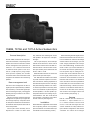
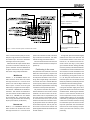
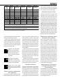
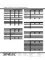
LSE Series
Operating Manual
Genelec 7060B, 7070A and 7071A
Active Subwoofers
7060B, 7070A and 7071A Active Subwoofers
General description
Genelec 7060B, 7070A and 7071A are pow-
easy subwoofer level matching with various
Before connecting the audio signals, ensure
main speakers. All outputs have 0 dB pass-
that both the subwoofer and the main moni-
band gain.
tors are switched off. Check that the voltage
erful active subwoofers, incorporating all the
The low pass frequency of the LFE input
selector switch is set according to your local
amplifier and crossover electronics needed
channel can be set to 85 Hz, 120 Hz or 85 Hz
mains voltage (subwoofers sold in Europe
for bass management and reproduction in
with "Redirect" function that routes LFE con-
have a fixed 230V setting). Connections are
modern 6.1 or 5.1 channel surround sound
tent above 85 Hz to the front center monitor.
easier to make if you roll the subwoofer on
or traditional stereo systems. Their 19 to
The input sensitivity of the LFE channel can
its side with the connector panel facing up.
120 Hz (±3 dB) frequency range, ample
be set to 0 dB or +10 dB.
Use this position only for making the con-
sound pressure capability and versatile
connections make these subwoofers ideal
companions for Genelec's active monitoring
speakers.
Bass management unit
Balanced XLR connectors are used for the
system audio inputs and outputs.
nections and roll the subwoofer back to its
normal upright position before use. Audio
Two "Bass Roll-Off" switches are included
connections to the subwoofer are made via
to provide a flat bass response in all acous-
balanced XLR connectors. An unbalanced
tical environments, enabling adjustments of
source can also be used with a special RCA
the subwoofer response in three -2 dB steps.
to XLR cable; the correct connection for the
The built-in bass management unit has six
Two phase matching switches in the crosso-
cable is shown in Fig. 2. However, we recom-
signal input and output channels (L/C/R Front
ver allow compensation for the delay which
mend the use of balanced cables and con-
and L/C/R Rear), a discrete LFE signal input
occurs if the subwoofer is placed away from
nectors due to their better noise immunity.
and a summed signal output, providing great
the main speakers, or for other speaker sys-
The connectors are arranged in three rows
flexibility and easy connection in all monitor-
tems phase behaviour. Four settings are pro-
on the connector panel (see Fig. 1):
ing environments.
vided between 0° and -270°. An 85 Hz test
The active crossover contained in the bass
management unit splits the input signals into
low and high frequency components at 85
tone generator is included to help achieve
accurate crossover phase alignment.
Top row
LFE IN / SUM IN: Use this connector for
the LFE or .1 output channel of a 5.1-
Hz. Frequencies below 85 Hz are directed to
Installation
the subwoofer and frequencies above 85 Hz
Each subwoofer is supplied with a mains cable
source, or the SUM OUT signal from the
to the main speakers.
and an operating manual. Once unpacked,
"master" subwoofer in a daisy-chained mul-
place the subwoofer in a suitable location (for
tiple subwoofer configuration. Note that the
more details see the "Positioning" section).
"subwoofer out" channel of an analogue
The low pass section sensitivity can be
adjusted from +12 dBu to -6 dBu to allow
or 6.1-channel discrete surround sound
Figure 2. XLR to RCA connector for
unbalanced operation.
Figure 1. 7070A's connector panel, connectors and controls.
Figure 3. Recommended distances to
the front wall
matrix surround decoder (Dolby Surround,
system. The connection is made in the same
To begin with, place the subwoofer slightly
Dolby Pro Logic) should not be connected to
way as with the Front channels. Also these
offset from the center of the front wall. The
the "LFE IN" input. See section "Subwoofer
channels are high pass filtered at 85 Hz.
recommended distance to the wall is less
in analogue matrix sound systems".
SUM OUT: Use this output connector when
you want to link another subwoofer to your
system. "SUM OUT" carries an unfiltered sum
of signals combined from all input channels.
See section "Using multiple subwoofers".
Once all connections have been made, the
than 60 cm / 24" measured from the sub-
subwoofer and main monitors are ready to be
woofer's driver (See Fig. 3). This position
powered up.
gives increased acoustic loading (and SPL)
Positioning in the room
due to the proximity of the front wall and floor.
Cancellations from the front wall and floor are
The placement of the subwoofer in the room
also avoided. Front wall cancellation for the
affects the overall frequency response and
85 Hz high pass filtered main speakers can
Middle row
sound level of the system dramatically, as at
be eliminated by placing them at least 110
FRONT L, C, R CHANNELS IN/OUT: Use
low frequencies the effects of the room are
cm / 43" away from the front wall. In a mul-
these connectors for the Front Left, Center
strong. Even a slight change in the subwoof-
tichannel system the main monitors should
and Right channels of a surround sound
er's location can make a marked difference
ideally be positioned symmetrically and at an
system or the Left and Right channels of a
in the frequency balance and often patient
equal distance from the listening position.
Stereo system. Connect line level signal
and methodical experimentation and testing
cables from your signal source to their respec-
is needed to find the optimum placement.
If the frequency balance is not right, try
moving the subwoofer slightly to the left or
tive "LEFT IN", "CENTER IN" and "RIGHT IN"
The placement will affect the phase dif-
right so that different room modes are excited
connectors. Then connect the subwoofer to
ference between the main monitors and the
at different levels. Positioning the subwoofer
your main monitors with XLR cables from the
subwoofer, and also the bass roll-off rate.
close to a corner will boost the bass level
"LEFT OUT", "CENTER OUT" and "RIGHT
These effects can be compensated by the
at lower frequencies and may cause asym-
OUT" connectors. All "L, C and R OUT" chan-
use of the controls in the amplifier unit; but
metrical spatial imaging. If you are using two
nels are high pass filtered with the filtering
we recommend that at first you leave the
subwoofers, try placing them asymmetrically
frquency fixed at 85 Hz (12 dB/octave).
switches untouched and concentrate on find-
relative to the side walls. Sometimes moving
ing the position where the subwoofer gives
the subwoofers apart into the front corners
Bottom row
the smoothest response, and only then use
helps with problematic rear wall reflections
REAR L, C, R CHANNELS IN/OUT: Use
the controls to fine-tune the balance and
and the loss of mutual coupling is compen-
these connectors for the Rear Left, Center
phase alignment between the subwoofer and
sated by the bass boost caused by corner
and Right channels of a surround sound
the main monitors.
positioning.
Subwoofer placement
Phase Difference: 0°
85 Hz
Phase Difference: 90°
Bass Roll-Off
setting
Near to a wall
-2 dB
In a corner
-6 dB
Flush mounted
-2 dB
Table 1. Suggested Bass Roll-Off settings
85 Hz
Phase Difference: 270°
Phase Difference: 180°
85 Hz
85 Hz
Figure 4. The effect of phase difference between the subwoofer and the main monitors
Figure 5. Flush mounting the subwoofer.
Note the clearance needed on the reflex
port side.
Although the 7060B, 7070A and 7071A
fier cooling. This can be done by making the
panel. Table 1 provides some suggestions
subwoofers are magnetically shielded, they
recess 7,5 centimeters (3") wider than the
for the "Bass Roll-Off" switch settings. When
may cause some picture distortion if placed
subwoofer. Place the subwoofer into the right
both roll-off switches are set to "OFF", a flat
near very sensitive video monitors or com-
end of the recess with the driver side facing
anechoic response is obtained.
puter displays. Move the subwoofer further
the room. This leaves sufficient 7,5 centime-
away or try turning the driver side of the
ters (3") of free space on the reflex port side.
Setting the phase control
subwoofer away from the screen.
The height and depth of the recess should
Incorrect phase alignment between main
not be any bigger than those needed to fit
monitors and subwoofer causes a drop in the
the subwoofer flush with the wall surface.
frequency response of the whole system at
Minimum clearances to walls
or other objects
the crossover frequency. The graphs above
The power amplifiers are attached to the
Setting the input sensitivity
lower part of the aluminium grille, which func-
The subwoofer requires input sensitivity
tions as a heatsink. Do not cover the grille
alignment to the source to obtain a correctly
The phase difference between the main
or place the subwoofer so that there is less
balanced system. The input sensitivity con-
monitors and subwoofer at the listening posi-
than 10 centimeters (4") of free space in front
trol is located on the connector panel of the
tion is dependent upon the position of the
of the grille.
(Fig. 4) show the effect of phase difference
to the frequency response.
subwoofer. An input voltage of -6 dBu with a
subwoofer, so the phase adjustment should
Make sure that the space underneath the
-6 dBu input sensitivity setting will produce
be done only after the preferred position is
subwoofer is clear from obstructions. Thick
100 dB SPL @ 1m in free field. To obtain a
found. Acoustic measuring equipment is
carpets may block the ventilation clearance
110 dB SPL output an input voltage of +10
required for accurate system alignment. If
needed for cooling the electronics' box.
dBu is required when the input sensitivity is
this equipment is not available, the following
set to 0 dBu.
coarse phase matching can be applied.
The reflex port side (opposite of the connector panel side) should always have a
Setting the Bass Roll-Off
switches
Coarse phase adjustment
method
The acoustic response of the subwoofer may
Genelec 7060B, 7070A and 7071A
have to be matched to the characteristics of
subwoofers are equipped with a built-in 85
the room and the positioning in which it will
Hz frequency test tone generator for easy
If the subwoofer is flush mounted into a wall
be used. To adjust the subwoofer to match
phase alignment. The test tone generator
or a cabinet, it is important to ensure unre-
these characteristics use the ''Bass Roll-Off'
is connected to the subwoofer's "FRONT
stricted airflow from the reflex port and ampli-
control switches located on the connector
CENTER OUT" channel only. In a stereo
clearance of at least 7,5 centimeters (3") to
any objects to ensure proper functioning of
the reflex port.
Flush mounting the subwoofer
Maximum
room
volume,
m3 (ft3)
Maximum
listening
distance,
m (ft)
Front
loudspeakers
Stereo & LCR
Side and rear
loudspeakers
Subwoofers
for 2-channel
Stereo
Subwoofers
for 5-channel
Surround
can be used to bring it into view. The kit consists of a LED in a compact case and a RJ11
cable to connect the case and the "REMOTE"
RJ11 connector on the connector panel.
75
(2,600)
2.0m (6’7”)
8030A
8030A
7050B
7060A
75
(2,600)
2.0m (6’7”)
8130A
8130A
7050B
7060A (1)
85
(3,000)
2.2m (7’3”)
8040A
8040A
7060B
7070A
Subwoofer bypass control
95
(3,400)
2.3m (7’7”)
8050A
8050A
7070A
7070A
A bypass control feature is included in the
110 (3,900)
2.4m (7’10”)
1032A
1032A
7070A
7071A
subwoofer circuits so that the effect of the
125 (4,400)
3.5m (11’6”)
1037C
1037C
7071A
2x7071A
subwoofer on the whole monitor system can
170 (6,000)
4.0m (13’1”) 1038B & 1038BC
1038B
7071A
2x7071A
be determined. With the bypass switch on,
200 (7,000)
4.5m (14’9”) 1034B & 1034BC
1038B
7071A
2x7071A (2)
the high pass filters for the main monitors are
240 (8,500)
4.7m (15’5”)
1039A
1038B
2x7071A
2x7071A (2)
overridden and the system behaves as if the
400 (14,000)
5.5m (18’1”)
1035B
1038B
2x7071A (2)
3x7071A (2)
subwoofer was not connected. The bypass
400 (14,000)
5.5m (18’1”)
1036A
1038B
(3)
(3)
(1)
When using a digital input signal, the 8130A cannot be used with the subwoofer’s analogue crossover
filters. The subwoofer can be used for reproducing the LFE channel only.
(2)
Additional subwoofers of the same type may be required in a larger room with bass heavy program material.
(3)
Subwoofers are not necessarily required for a 1036A installation as these monitors are already full range.
For surround systems, subwoofers can be used to reproduce the LFE channel.
Table 2. Recommended subwoofer/main monitor combinations.
function has no effect on the LFE input. Two
different bypass remote controllers are available as optional equipment: 1092-400 switch
that can be connected to a 1/4" jack connector on the connector panel and 7000-416 that
connects to the "REMOTE" RJ11 connector.
The 7000-416 option also includes remote
control of the "LFE +10 dB" function and a
link for the 7000-415 remote LED option.
noise generator. Connect a high grade
Subwoofer in analogue matrix
surround sound systems.
Power up the system and set the DIP
measuring microphone to the analyser and
When using Genelec 7060B, 7070A or
switches 3 (SUM IN MODE) and 4 (LFE +10
feed pink noise into the "CENTER IN" input
7171A subwoofers in a consumer analogue
dB) on the first switch group to "ON" Now you
of the subwoofer. The subwoofer's bass
matrix surround sound system, such as
should hear an 85 Hz test signal from the
management system will direct the frequen-
Dolby Surround, Dolby Pro-Logic or Pro-
subwoofer and the main monitor connected
cies above 85 Hz to the center main monitor
Logic II or a professional matrix decoder
to the center channel output.
while the subwoofer reproduces the frequen-
such as a Dolby SDU-4, route the front chan-
cies below 85 Hz.
nels through the subwoofer so that the output
system it is necessary to temporarily connect
tors using a frequency analyser and a pink
either of the channels to this output.
Toggle the -180° phase switch
Position the microphone at the listening
of the subwoofer is matched to the rest of the
(DIP 4 on the second switch
position and adjust the input sensitivity of
system and select "Large" setting for the
group) on and off, and set it to
the subwoofer until frequencies below and
front speakers on the decoder. If there is a
the position which gives the
above 85 Hz are reproduced at equal level.
subwoofer channel output on the decoder it
lowest sound level at the listen-
Then adjust the phase control switches for
should NOT be connected to the subwoofer's
ing position.
the maximum dip of at least -6 dB at the
"LFE IN" input since the processing within an
crossover frequency (85 Hz).
analogue decoder will conflict with the filter-
Next toggle the -90° phase
Change the -180° switch to the opposite
ing in the subwoofer. Connecting the rear
switch (DIP 3) on and off, and
setting. The phase should now be set cor-
channels to the subwoofer is optional since
again set it to the position which
rectly and the frequency analyser should
the rear channels from most matrix decoders
gives the lowest sound level.
show a smooth response around 85 Hz.
are band limited down to 100 Hz.
Finally, set the -180° phase
Overload indicators
switch (DIP 4) to the opposite
The mode indicator LED on the connector
setting and deactivate the test
panel will turn from green to yellow to indi-
Monitoring the LFE channel
in digital discrete surround
sound systems
signal.
cate clipping and then to red to indicate that
Some digital surround sound systems use
the protection circuit has activated. If this
a discrete Low Frequency Effects channel
occurs frequently, reduce the input level to
which should be connected to the "LFE IN"
the subwoofer until the LED remains green.
input on the connector panel. This enables
Phase correction method with
test equipment
The following procedure matches the phase
If the LED on the connector panel is not
between the subwoofer and the main moni-
easily visible, the optional Remote LED Kit
the subwoofer to correctly reproduce all the
bass information in the mix.
The LFE channel on the 7060B, 7070A and
+10 dB gain in relation to the main channels.
woofer in the chain, especially if they are not
7071A can be set to two frequency ranges:
The object is to increase the recording head-
placed close together. To check the phase
19 to 85 Hz or 19 to 120 Hz by using the
room of the LFE channel. Consumer and the-
alignment for the "master" subwoofer switch
"LFE BANDWIDTH" switch. If the LFE signal
atrical decoders automatically add +10 dB of
off the "slave" subwoofer and follow the
includes higher frequencies than 120 Hz,
LFE gain to restore the level balance.
instructions given in the previous sections.
they can be monitored by using the "Redi-
The "LFE +10 dB" function on the 7060B,
To adjust the phase alignment of the
rect" function: Set "LFE BANDWIDTH" switch
7070A and 7071A subwoofers is designed to
"slave" subwoofer, you need to switch off
to "85" and the "REDIRECT" switch to "ON".
add the +10 dB gain to the LFE channel in the
the "master" subwoofer, connect a signal
Now the subwoofer reproduces LFE frequen-
production stage, if it is not already done in
cable from the "slave" subwoofer's "FRONT
cies up to 85 Hz and reroutes all higher LFE
the output matrix of the mixing console. The
CENTER OUT" connector to the center chan-
content to the front center channel. This is
function is activated by switching the "LFE
nel monitor and switch the "SUM IN MODE"
the most flexible setting for LFE signal man-
+10 dB" dip switch on the subwoofer's first
switch to "OFF". This effectively changes
agement, as it ensures that all LFE content
switch group to "ON" or by using the remote
the "slave" to "master" mode and the phase
can be monitored in all situations and encod-
control. A yellow LED indicates that the func-
adjustment can be carried out. Return the
ing formats. Note that the "Redirect" function
tion has been activated.
connections and "SUM IN MODE" setting on
is not enabled when the "LFE BANDWIDTH"
switch is set to 120 Hz.
Typical applications of different
LFE bandwidth settings
The "LFE +10 dB" function should not be
used in following cases:
the "slave" subwoofer back to the "SUM IN"
mode after completing the adjustment.
• If the +10 dB LFE gain is already
Safety considerations
implemented by another device.
The LSE series subwoofers have been
As stated above, using the 85 Hz LFE band-
• When producing an audio format that
width setting with "Redirect" function is the
does not require the use of +10 dB
safety standards. However, to ensure safe
most universal configuration for LFE monitor-
gain on the LFE channel, such as
operation and maintain the unit in safe oper-
ing. However, there are situations when the
DVD-Audio (MLP), SACD (DSD) etc.
ating condition, the following warnings and
band-limited LFE settings serve a definite
purpose.
Limiting the LFE bandwidth to 85 Hz without
using the "Redirect" function can be used to
simulate the effect of some consumer decod-
• When monitoring a decoded Dolby
Digital or DTS soundtrack. The decoder
will automatically provide +10 dB
LFE gain.
designed in accordance with international
cautions must be observed:
• Do not expose the subwoofer to water
or moisture. Do not place any objects
filled with liquid, such as vases on
ers that do not replay information above 80
Using multiple subwoofers
Hz on the LFE channel when the bass man-
Genelec 7060B, 7070A and 7071A subwoofers
agement is used. Checking the multichannel
are equipped with a "SUM OUT" connector to
lighted candles on or near the
mix with this setting on lets you know how it
provide an easy way of coupling two or more
subwoofer
translates in systems with this limitation.
the subwoofer or near it.
• Do not place naked flame sources like
subwoofers together in high SPL applications.
• Servicing and adjustment must only
The 120 Hz LFE bandwidth setting com-
Table 2 shows the recommended configura-
be performed by qualified service
plies with the replay systems of movie theat-
tions with different Genelec monitors. Connect
ers and cinemas. 35 mm movie soundtracks
an XLR cable from the "SUM OUT" connector
use the LFE channel to reproduce a band-
of the "master" subwoofer to which the main
width of 20 - 120 Hz through dedicated
monitor channels are connected, to the "LFE
subwoofers. In this case the LFE and main
IN / SUM IN" connector of the other, "slave"
• Always use a mains power connection
channel bandwidths overlap between 85 and
subwoofer and turn the "SUM IN MODE" dip
and cable with protective earth. Failing
120 Hz, which may create unwanted acous-
switch on the "slave" subwoofer to "ON".
personnel.
• Opening the connector panel is
strictly prohibited except by
qualified service personnel.
to do this may lead to personal injury.
• Note that the amplifier is not completely
tical summing if the same signal is present
When two subwoofers connected in this
in both channels. To avoid this, the LFE con-
way are positioned close to one another,
disconnected from the AC mains
tent should be kept completely different (de-
bass level increases by 6 dB. Three sub-
service unless the mains power cord
correlated) from the low frequency content
woofers give an SPL increase of 9,5 dB and
is removed from the amplifier or the
of the main channels when mixing music
four subwoofers 12 dB compared to a single
mains outlet.
and sound effects for film release.
subwoofer. Adjust the sensitivity control of all
Using the LFE +10 dB function
subwoofers in the group to match the SPL
Warning!
level of the main monitor system.
This equipment is capable of delivering sound
In Dolby Digital and DTS encoding formats
Phase and Bass Roll-Off adjustments
the LFE channel has to be monitored with
should be done individually for each sub-
pressure levels in excess of 85 dB, which
may cause permanent hearing damage.
Figure 6. 1092-400 "Bypass" switch
Figure 7. 7000-415 Remote
Power/OVL LED
Figure 8. 7000-416 Remote control switch
for "Bypass" and "+10 dB LFE" functions
Maintenance
No user serviceable parts are inside the amplifier unit. Any maintenance work must only be
performed by qualified service personnel.
Guarantee
This product is supplied with a one year guarantee against manufacturing faults or defects
that might affect the performance of the unit.
Refer to supplier for full sales and guarantee
terms.
Accessories
1092-400
1/4” jack "Bypass" switch
7000-415
RJ11 remote Power/Overload
indicator LED
7000-416
RJ11 remote control for
"Bypass" and "+10 dB LFE"
functions
EC Declaration of Conformity
This is to certify that Genelec 7060B, 7070A
and 7071A active subwoofers conform to
the following standards:
Safety:
EN 60065 / IEC 60065:1998 7th Edition
EMC:
EN 55013: (2001)
EN 55020: (1994), A11: (1996), A12: (1999),
A13: (1999), A14: (1999)
EN 61000-3-2 (2000), EN 61000-3-3 (1995)
The products herewith comply with the
requirements of The Low Voltage Directive
73/23/EEC, EMC Directive 89/336/EEC and
93/68/EEC
Signed:
Ilpo Martikainen
Position: Chairman of the Board
Date:
28-February-2006
Figure 9. The free field frequency response
of the 7060B subwoofer at different Bass
Roll-Off settings
Figure 10. The free field frequency
response of 7070A and 7071A subwoofers
at different Bass Roll-Off settings.
7060B, 7070A and 7071A Operating Manual
SYSTEM SPECIFICATIONS
Free field frequency response
(+/- 3 dB)
Maximum short term sine wave
SPL output averaged from
30 to 85 Hz, measured in
half space at 1 meter
AMPLIFIER SECTION
7060B
7070A
7071A
19 Hz…85 Hz
LFE 85/120 Hz
19 Hz…85 Hz
LFE 85/120 Hz
19 Hz…85 Hz
LFE 85/120 Hz
≥ 108 dB SPL
Maximum peak SPL output with
random pink noise, measured
in half space at 1 meter
≥ 113 dB SPL
Self generated noise level in
free field @ 1 m on axis
(A-weighted)
≤ 15 dB
Harmonic distortion
at @ 1 m on axis in half space
2nd
3rd
@ 90 dB SPL
30 … 85 Hz
≤3%
≤2%
≥ 112 dB SPL
≥ 118 dB SPL
≥ 117 dB SPL
≥ 123 dB SPL
7060B
7070A
7071A
Short term amplifier output
power (Long term output power
is limited by driver unit
protection circuitry)
120 W
250 W
500 W
Amplifier system distortion
at nominal output
THD
≤ 0.05%
Mains voltage
230 V, 115/230V or 100/200V
according to region
Power consumption (average)
Idle
Full output
@ 95 dB SPL
30 … 85 Hz
≤3%
≤3%
15 VA
150 VA
15 VA
250 VA
30 VA
500 VA
7060B
7070A
7071A
@ 100 dB SPL
30 … 85 Hz
≤3%
≤3%
Driver, magnetically shielded
250 mm (10”)
305 mm (12”)
2 x 305 mm (12”)
Weight
26 kg (57 lbs)
50 kg (110 lbs)
81 kg (178 lbs)
Dimensions
Height
Width
Depth
527 mm (20 3/4”)
462 mm (18 3/16”)
363 mm (14 5/16”)
625 mm (24 5/8”)
555 mm (21 7/8”)
490 mm (19 5/16”)
755 mm (29 3/4”)
803 mm (31 5/8”)
490 mm (19 5/16”)
INPUT SECTION
Input connector XLR female
pin 1
pin 2
pin 3
gnd
+
–
Input impedance
10 kOhm balanced
Input level for 100 dB SPL
output @ 1 m
Variable from +12 to –6 dBu
CROSSOVER SECTION
7060B
7070A
7071A
Subsonic filter
(18 dB/octave) below
19 Hz
19 Hz
19 Hz
Crossover frequency,
(sub/main channels)
85 Hz
LFE cutoff Hz
85 Hz/120 Hz selectable
Crossover slopes
Lowpass
Highpass
36 dB/octave
12 dB/octave
Midband rejection >400 Hz
≥ 50 dB
Bass Roll-Off control operating
range in 2 dB steps
From 0 to –6 dB
@ 20 Hz
Phase matching control
in 90° steps
From 0 to 270
@ 85 Hz
OUTPUT SECTION
7060B
From 0 to –6 dB
@ 20 Hz
Output connector XLR male
pin 1
pin 2
pin 3
From 0 to –6 dB
@ 20 Hz
7070A
7071A
gnd
+
–
Remote LED connector (RJ11)
Remote LED for Power/Overload+Bypass and LFE +10 dB
Main monitor Out gain
0 dB
Sum Out gain
0 dB
CONTROLS
7060B
7070A
7071A
Input sensitivity
+12 to –6 dBu for 100 dB @ 1 m
Bypass
Bypasses the bass management for the main channels
LFE bandwidth
85 / 120 Hz
LFE sensitivity
0 / +10 dB
Redirect
Redirects LFE channel signal above 85 Hz to center channel
Sum in
Changes subwoofer to Sum in mode
Test tone for phase adjustment
85 Hz
Bass Roll-Off
0/-2 dB/ -4 dB/ -6 dB 0/-2 dB/ -4 dB/ -6 dB
@ 20 Hz
@ 20 Hz
Phase
0/90/180/270° @ 85 Hz
0/-2 dB/ -4 dB/ -6
dB @ 20 Hz
www.genelec.com
Genelec Document D0032R001b. Copyright Genelec Oy 3.2006. All data subject to change without prior notice
International enquiries:
In the U.S. please contact
In China please contact:
In Sweden please contact
Genelec, Olvitie 5
Genelec, Inc., 7 Tech Circle
Beijing Genelec Audio Co. Ltd.
Genelec Sverige
FIN-74100, Iisalmi, Finland
Natick, MA 01760
Jianwai SOHO, Tower 12, Room 2306
Ellipsvägen 10B
Phone +358 17 83 881
Phone +1 508 652 0900
39 East 3rd Ring Road
P.O. Box 5521, S-141 05 Huddinge
Fax +1 508 652 0909
Chaoyang District
Phone +46 8 449 5220
Email [email protected]
Beijing 100022, China
Fax +46 8 708 7071
Phone +86 0 5869 7915, Fax +86 10 5869 7914
Email [email protected]
Fax +358 17 812 267
Email [email protected]