1
Documax 5380
24-Pin Dot Matrix Printer
User’s Guide
© March 2013, AMT Datasouth Corp.
Document # 131022
Copyright Declaration
Information in this manual is subject to change without notice and does not represent a
commitment on the part of AMT Datasouth Corporation. No part of this manual may be
reproduced or transmitted in any form by any means, for any purpose other than the
purchaser’s personal use, without the expressed written permission of AMT Datasouth
Corporation.
Trademark Credits:
EPSON is a registered trademark of Seiko Epson Corporation.
ESC/P-K2 is a registered trademark of Seiko Epson Corporation.
OKI is a registered trademark of Oki Data Corporation.
OKI 5530SC is a registered trademark of Oki Data Corporation.
Windows is a registered trademark of Microsoft Corporation.
Regulatory Statement:
FCC
This device complies with Part 15 of the FCC Rules.
Operation is subject to the following two conditions:
Class B
(1) This device may not cause harmful interference, and (2)
this device must accept any interference received, including
interference that may cause undesired operation.
The manufacturer is not responsible for any radio or TV
interference caused by unauthorized modifications to this
equipment. Such modifications could void the user’s
authority to operate the equipment.
LISTED
16PU
NWGQ
E247562
120VAC ~ 60Hz ~ 1.0A
AMT Datasouth Support:
http://www.amtdatasouth.com/support-1/downloads/
- ii -
Table of Contents
User Caution...................................................................................................................5
Packaging .......................................................................................................................6
Unpacking the printer .................................................................................................................................... 6
Removing protective material ........................................................................................................................ 6
Part identification ........................................................................................................................................... 7
Installation ......................................................................................................................8
Installing paper support ................................................................................................................................. 8
Installing the ribbon cartridge ........................................................................................................................ 9
Connecting the printer to the power source ................................................................................................ 10
Connecting the printer to the PC ................................................................................................................. 11
Loading Paper .............................................................................................................. 13
Paper thickness adjustment ........................................................................................................................ 13
Loading cut-sheet paper/forms .................................................................................................................... 13
Loading tractor paper .................................................................................................................................. 15
Tractor paper tear off ................................................................................................................................... 17
Top of form adjustment ................................................................................................................................ 18
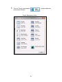
Print Driver Installation ............................................................................................... 19
Win2000 (XP~Vista~Win7) .......................................................................................................................... 19
Printer settings via driver ............................................................................................................................. 20
Control Panel................................................................................................................ 23
Indicator LED’s ............................................................................................................................................ 23
Basic control panel operations .................................................................................................................... 23
Printer settings via printer control panel ...................................................................................................... 24
Factory default settings ............................................................................................................................... 25
Printer setting definitions ............................................................................................................................. 26
Ethernet Interface Settings ......................................................................................... 28
NetFinder search ......................................................................................................................................... 28
Setting printer static IP address................................................................................................................... 29
-3-
Diagnostic Testing ....................................................................................................... 32
ASCII Self-test ............................................................................................................................................. 32
Print head pin test ........................................................................................................................................ 32
Hex dump mode .......................................................................................................................................... 32
Interface Specification ................................................................................................. 33
USB 2.0 full speed interface ........................................................................................................................ 33
Serial DB-25 interface ................................................................................................................................. 33
Ethernet interface ........................................................................................................................................ 35
Parallel interface .......................................................................................................................................... 36
Printer Maintenance..................................................................................................... 37
Printer Specification .................................................................................................... 38
-4-
Operational
safety
User Caution
CAUTION
To avoid burns, do not touch the print
head immediately after printing.
Do not put your fingers under the tractor
covers while loading fanfold paper.
Cautions in setting up
Unplug this product from the power
outlet before cleaning.
Do not use this product near water.
Mechanical and electrical repairs
should be conduct by qualified
service personnel.
CAUTION
Unpack the printer. Make sure that the
printer body and all accessories are
included in the package and no parts are
damaged.
Place the printer on a rigid,
horizontal base in a location that is
free of vibration.
Do not use the printer in a location
exposed to direct sunlight or close to a
heater or other heat generating
equipment.
Before connecting or disconnecting
the interface cable, be sure to turn
off the printer.
Do not use the printer in a dusty location
or any location subject to sudden
changes in temperature and humidity.
Do not connect the printer to a nonstandard power source.
Never try to print without a ribbon
cartridge installed and paper loaded.
Take care not to twist the ribbon while
installing the ribbon cartridge.
If the case or cover becomes dirty,
clean it with a soft cloth moistened
with a small quantity of neutral
detergent diluted with water. Never
use a hard cloth or volatile solvent
such as alcohol, thinner, or benzene.
Do not turn off the printer during
printing, as this may lead to a
malfunction.
Push the lock levers of both tractors to
the LOCK positions firmly when loading
fanfold paper.
-5-5-
Rear Operating Clearance
Fanfold Paper: 2” plus Paper Length
Manual Cut Sheets: Paper Length
Minus 9”
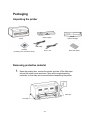
Packaging
Unpacking the printer
Paper Support
Printer
Ribbon Cartridge
USB Cable
CD ROM
(Including user's manual and driver)
Power Cord
Quick Start Guide
Removing protective material
1.
Open the packing box, remove the printer and tear off the fiber tape
around the printer cover as shown. Save all the original packing
materials, so that they can be reused when transporting the printer.
Fiber tape
Fiber tape
-6-
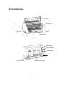
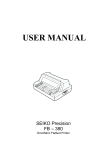
Part identification
Top Cover
Gap adjust lever
Ribbon cartridge
Control panel
Pinch roller
assembly
Power switch
Paper guide
Paper support
Print head
Serial interface
Ethernet interface
USB interface
AC Power inlet
Paper select lever
Paper Tractor assembly
-7-
Installation
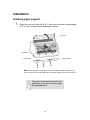
Installing paper support
1.
Open the top cover, align the A, B, C tabs over the printer corresponding
A, B, C slots, and then press downward to fasten.
Top cover
Guide Slots
Paper support
Paper guide
Note: When transporting the printer remove the paper support. Open the Top
Cover, lift up on the left and right side of the paper support evenly until removed.
The paper guide should be positioned
all the way to the right for proper paper
left edge alignment.
-8-
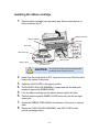
Installing the ribbon cartridge
1.
Remove ribbon cartridge from the plastic bag. Remove and dispose of
ribbon retainers (qty-2).
2
Ribbon feed knob
7
3
Ribbon cartridge
Gap lever
Print head
Head carrier pin
4
6
Pinch roller assembly
5
Ribbon mask
Ribbon guide
CAUTION
Do not touch the print head immediately after
printing because it may be too hot.
2.
Make sure the power switch is OFF. Open the front cover. Move the print
head to the center of the printer.
3.
4.
Adjust the GAP LEVER to the highest position.
5.
6.
Lock the ribbon cartridge into the printer chassis (right & left side).
7.
Rotate the RIBBON FEED KNOB in the direction of the arrow to remove
slack.
8.
Return the PINCH ROLLER ASSEMBLY and GAP LEVER to their
normal operating position.
Pull the PINCH ROLLER ASSEMBLY forward and turn the back side
upward to expose the RIBBON MASK.
Carefully slide the plastic RIBBON GUIDE holes onto the left and right
carrier pins.
-9-
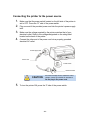
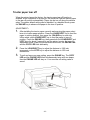
Connecting the printer to the power source
1.
Make sure that the power switch located on the left side of the printer is
set to OFF. Press the “O” side of the power switch.
2.
Plug one end of the provided power cord into the printer’s power supply
inlet.
3.
Make sure the voltage required by the printer matches that of your
electrical outlet. Refer to the voltage designated on the rating label
located on the back of the printer.
4.
Connect the other end of the power cord into a properly grounded
electrical AC outlet.
Power supply inlet
Power cord
打印机
Power switch
Electrical outlet
打印机
打印机
CAUTION
If the rated voltage doesn’t match the outlet
voltage, contact your dealer for assistance.
Do not plug in the power cord.
5.
To turn the printer ON, press the “I” side of the power switch.
- 10 -
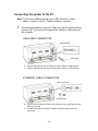
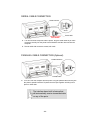
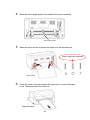
Connecting the printer to the PC
Note: The Documax 5380 printer can use a USB, Ethernet, or Serial
cable to connect to the PC. Parallel interface is optional.
1.
Install desired interface connection. Make sure that the power switch is
turned to OFF and connect the appropriate cable(s) to the printer and
the computer.
USB CABLE CONNECTION
USB interface
USB cable
Plug the USB cable A end (flat shape) into the computer's USB interface.
Plug the USB cable B end (square shape) into the printer's USB interface.
ETHERNET CABLE CONNECTION
Ethernet interface
Ethernet cable
Plug one end of the RJ-45 cable into the Ethernet port of the printer and the
other into the LAN.
Use NetFinder utility to identify IP address and help complete interface
connection.
- 11 -
SERIAL CABLE CONNECTION
Serial interface
Screw
Serial cable
Cable type must be
NULL MODEM
Turn OFF both the computer and the printer. Plug the serial cable 25-pin male
connector securely into the printer's serial interface and the other end into the
computer.
Secure cable with connector screws, both ends.
PARALLEL CABLE CONNECTION (Optional)
Parallel interface
Wire clips
Parallel cable
Turn OFF both the computer and the printer. Plug the parallel cable securely into
the printer's parallel interface. Squeeze the wire clips together until they lock in
place on either side.
The interface has a built in feature that
will automatically receive transmitted data
on any of the ports.
- 12 -
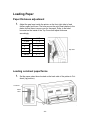
Loading Paper
Paper thickness adjustment
Adjust the gap lever inside the printer on the front right side to feed
thicker paper and forms. The lever moves the print head relative to the
platen so that there is more room for the paper. Refer to the label
mounted on the inside of the Top Cover and adjust thickness
accordingly.
MEDIA
GAP
OTHER
7~9
6~7
5
4
2~3
SINGLE
MULTI-PART
1.
5~6
4
3
Gap lever
2
0~1
Loading cut-sheet paper/forms
1.
Set the paper select lever located on the back side of the printer to Cutsheet (up position).
Cut-sheet
Select
Lever
- 13 -
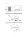
2.
Position the paper guide to the furthest right position.
Paper
Guide
3.
Pull tray extension out for long paper/forms requiring extra support.
Tray
Extension
4.
Insert the paper as shown below, the paper is fed into the printer
automatically.
- 14 -
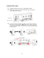
Loading tractor paper
1.
2.
Set paper thickness lever, refer to “Loading Paper” section.
Set the paper select lever located on the back side of the printer to
Tractor Paper (down position).
Tractor paper
Paper select lever
3.
Loosen the left and right tractors by lifting up on lock levers. Adjust the
left tractor to the home position (“▽” denotes home). Adjust right tractor
to approximate paper width. Lock left tractor into place by pressing down
on the lock lever.
Unlocked
locked
Home Position
- 15 -
4.
Move the tractor paper guide to the middle of the tractor assembly.
Tractor Paper Guide
5.
Open the tractor covers and place the paper onto the sprocket pins.
Proper Paper Hole Alignment
Tractor Covers
6.
Close the tractor covers and adjust the right tractor to ensure the paper
is flat. Then press down the lock lever.
Paper Direction
- 16 -
Tractor paper tear off
When the printer leaves the factory, the tractor paper tear off function is
enabled. At the completion of a print job, the printer will feed the tractor paper
to the tear off position automatically. Paper can be torn off along the window
edge. The printer default setting can be disabled. In a disabled mode, press
the ONLINE key to advance the paper to the tear off position.
ADJUSTMENT ~
1.
After installing the tractor paper correctly and ensuring the paper select
lever is in tractor paper position .Press the LOAD/EJECT key to feed the
paper to printing position, then press the ONLINE key to enter into
offline mode, press LOAD/EJECT key to feed the paper to tear off
position. Press the ONLINE key, then press both the LOAD/EJECT and
LF/FF keys for about 3 seconds to get the printer to enter the tear-off
adjustment mode. When the printer enters this mode, the ONLINE LED
and the COPY LED blink alternately.
2.
Press the LOAD/EJECT key to adjust the distance in 1/60 inch
increments, or the LF/FF key to adjust the distance in 1/60 inch
decrements.
3.
To exit and save your new setting, press the ONLINE key. The COPY
LED and the ONLINE LED blink simultaneously twice with two beeps,
then the ONLINE LED will stay on. Your new tear-off setting value is
saved.
- 17 -
Top of form adjustment
The top of form setting determines the margin between the top of paper and
the first printed line (the top margin). The top of the first printed line is the
zero position. Advancing the paper is a positive value, reversing the paper is
a negative value.
When the menu setup mode has specified the left black mark or right black
mark, this is defined as the distance from the black mark to the left or right
edge of paper.
TOF ADJUSTMENT ~
1.
Install paper correctly, press LOAD/EJECT key to feed paper to printing
position. In the ONLINE mode, press the LOAD/EJECT key and LF/FF
key for about 3 seconds at the same time, ONLINE LED and COPY LED
blinks alternately which denotes the printer has entered the adjustment
mode.
2.
Press the LOAD/EJECT key to increase the top of form by 1/60 inch.
You can increase the margin to a maximum of +60 increments (+60/60
inch) from the factory setting. Press the LF/FF key to decrease the top of
form by 1/60 inch. You can decrease the margin to a minimum value of 0
(-19/60 inch) from the default setting.
3.
Press the ONLINE key to exit and save your new setting. The COPY
LED and ONLINE LED blink simultaneously twice with two beeps, and
then the ONLINE LED will stay on.
BLACK MARK ADJUSTMENT ~
1.
Install paper correctly, press LOAD/EJECT key to feed paper to printing
position. In the ONLINE mode, press the LOAD/EJECT key and LF/FF
key for about 3 seconds at the same time, ONLINE LED and COPY LED
blinks alternately which denotes the printer has entered adjustment
mode.
2.
Press the LOAD/EJECT key to adjust the sensor position 1/20 inch. You
can increase the margin to a maximum of +80 increments (+80/20 inch)
from the factory setting, or the LF/FF key to decrease the margin to a
minimum of 0 (0/20 inch) from the default setting.
3.
Press the ONLINE key after adjusting, the COPY LED and ONLINE
LED blink simultaneously twice with two beeps, the new setting will be
saved, then press the ONLINE key again to exit the adjustment mode
entirely.
- 18 -
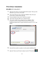
Print Driver Installation
Win2000 (XP~Vista~Win7)
1.
Open the driver folder on the CD shipped with the printer. Then open the
subfolder for your version of Windows.
2.
Click on the “Setup.exe” file to begin the installation utility. Have your
printer ready to connect when instructed.
3.
4.
5.
If a pop-up window occurs, click “Install driver anyway”.
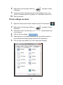
Click on the “Documax 5380” icon to select the driver.
Click on the “Install” button to begin the driver installation. When
prompted connect the interface cable and power ON the printer.
Installing the printer without a proper interface will result in a “LPT1” port
default.
4
5
6.
Once the Driver install is complete, close the printer installation utility.
7.
Open the “Devices and Printers” window from the PC Start button.
- 19 -
8.
Right-click on the Documax 5380 icon
Properties”.
9.
Choose the “Ports” tab and select the correct interface port for your
printer. For Ethernet port IP recognition, run “NetFinder” utility on CD.
10.
and select “Printer
End of procedure.
Printer settings via driver
1.
2.
Open the “Devices and Printers” window from the PC Start button.
Right-click on the Documax 5380 icon
Properties”.
and select “Printer
3.
Choose the “Ports” tab and verify, or select the preferred interface port
for your printer.
4.
5.
Click on “Printer settings”.
6.
Click on drop down window “Set” tab to select new setting(s).
Select and click on the printer setting icon you would like to adjust, a
pop-up window will display feature choice and an explanation.
- 20 -
7.
Click on “Printer maintenance”
printer setup features.
Printer Maintenance Menu
- 21 -
to access additional
8.
Click on “Advance printer setup”
additional printer setup features.
to access
Advance Printer Setup Menu
9.
Return to main menu and click on “OK” to exit and save settings.
- 22 -
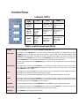
Control Panel
Indicator LED’s
Indicator
LED
Off
On
ONLINE
(green)
——
Lights when the
printer is online.
The printer is
offline or error
state.
Blink
COPY
{BOLD}
(green)
The printer
is in the
normal
mode.
The printer is in
the copy 1
mode.
The printer is in
the copy 2
mode.
SPEED
(green)
The printer
is in the
Letter
Quality
mode.
The printer is in
High Speed
Draft mode.
The printer is in
Super High
Speed Draft
mode.
Basic control panel operations
ONLINE
Press the ONLINE button, switch between ONLINE and OFFLINE modes.
LOAD/EJECT
When offline, press LOAD/EJECT key to control cut sheet or tractor paper feeding. In cut sheet mode, if you press
LOAD/EJECT key when offline, the paper will be ejected. In tractor paper mode, with paper installed, press
LOAD/EJECT key when offline. The paper will be fed to the print home position. The printer now being in the
online mode. Press ONLINE again, then press the LOAD/EJECT key, the paper will be fed to the tear position.
Press LOAD/EJECT key one more time, the paper will reverse feed back to the ready position.
In online mode, press and hold the LOAD/EJECT key for about 3 seconds, the printer will reverse feed the paper
in micro steps.
COPY {BOLD}
In the offline mode, press and hold ONLINE key for 3 seconds (until beep is heard), the printer will enter quick
menu setup mode. Press LOAD/EJECT key will select the normal print mode, copy 1 print mode or copy 2 mode.
Press ONLINE key to save setting.
LF/FF
In the offline mode, press the LF/FF key to feed the paper line by line. Alternatively, hold the LF/FF key down, the
printer will eject the cut sheet, or feed the tractor paper one page.
In the online mode, press and hold the LF/FF key for about 3 seconds will feed the paper in micro steps.
SPEED
In the offline mode, press and hold ONLINE key for 3 seconds (until beep is heard), the printer will enter quick
menu setup mode. Pressing LF/FF key will switch the printer among the letter quality mode, high speed mode and
super high speed mode. Press ONLINE key to save setting.
SETTINGS
To print current printer settings; Press LOAD/EJECT key and LF/FF key while turning ON printer power.
MENU SETUP
In the online mode, press and hold LOAD/EJECT key, and then press the ONLINE key. Hold keys for 3 seconds.
LED’s will blink. Load paper and follow printed instructions for feature settings.
SELF-TEST
Press ONLINE key while turning ON printer power.
- 23 -
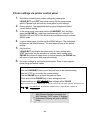
Printer settings via printer control panel
1.
With ribbon installed, print current settings by pressing the
LOAD/EJECT and LF/FF keys while turning ON the printer power
switch. Release keys and load cut sheet paper to print settings.
2.
Review printout. The highlighted settings (gray background) depict
current feature setting.
3.
In the online mode, press and hold the LOAD/EJECT key, and then
press the ONLINE key. Hold keys simultaneously for 3 seconds. The
ONLINE LED and COPY LED will blink twice simultaneously to indicate
MENU mode.
4.
Load cut sheet paper, the title and first MENU will print. The underlined
features are the default settings. The print head will stop at the default
setting.
5.
Key functions:
LOAD/EJECT key selects the menu option or menu setting value.
LF/FF key enters into the submenu or confirms menu setting value.
ONLINE key returns to upper menu (continue pressing the ONLINE key
will return to main menu and save new settings).
6.
Exit menu settings by cycling the printer power. Refer to next page for
menu listing and default values.
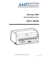
AMT Documax 5380 Current Settings
Use the LOAD/EJECT key to point the print head to the desired setting.
Use the LF/FF key to confirm the current setting.
Use the ONLINE key to go back the previous menu.
Press and hold the ONLINE key to save settings and exit.
Current settings are
New settings will be FILLED.
MAC: XX-XX-XX-XX-XX-XX DHCP: YES IP: 10.0.0.1 Subnet: 255. 255. 255.0 gateway: 255.255.255.255
SYSTEM SETUP CHARACTER PAGE LAYOUT PRINT SETUP SERIAL I/F
BREAK PIN
With Ethernet interface connected, the
MAC Address, DHCP status, IP Address
Subnet and Gateway will print on MENU
listing.
- 24 -
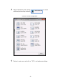
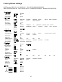
Factory default settings
AM AMT
Documax 5380 V2.0 U11 2013/01/15
SN: XXXXXXXXXXXXXXXXXXXX
MAC:XX-XX-XX-XX-XX-XX
DHCP:YES
IP:10.0.0.1
Subnet: 255.255.255.0 Gateway: 255.255.255.255
Factory default settings
LANGUAGE
EMULATION
CHAR. MODE
CHINESE
OKI
CHINA
FONT
ENG PITCH
SANS SER
12 CPI
CHI PITCH
7.5 CPI
SLASH ZERO
ON
INTL CHAR SE
JAPAN
COURIER
15 CPI
PRESTIGE SCRIPT
PROPORTIONAL
OCR-B
OCR-A ORATOR
FRANCE
NORWAY
GERMANY
DENMARK2
U.K.
DENMARK1 SWEDEN ITALY SPAIN 1
SPAIN 2
LATIN AM
KOREA
LEGAL HOLAND
8 LPI
11/3 INCH
3.5 INCH
4 INCH
12 INCH
14 INCH
TURKEY
GHAR. SET
ITALICS
LINE SPACING
FORM LENGTH
3 INCH
5 INCH
5.5 INCH 6 INCH 7 INCH
FORM LOCK
A4
ON
PAGE SKIP
ON
COMPRESS PRT
AUTO
75%
66%
50%
LEFT MARGIN
1/10 INCH
2/10 INCH
3/10 INCH
4/10 INCH
5/10 INCH
BLACK MARK
LEFT MARK
RIGHT MAR
004
005
PRINT DIR
BI-DIR
UNI-DIR
HIGH DENSITY
ON
QUIET MODE
ON
AUTO LF
LOADING
PUSH KEY
EJECT
PIN SWITCH
MARGIN DETEC
OFF
001
19200 BPS
PARITY
ODD
DATA BITS
7 BITS
STOP BITS
PROTOCOL
PIN 1
2.0 SEC.
REAR
ON
SKEW DETECT
BAUD RATE
ON
0.5 SEC.
002
003
4800 BPS
2400 BPS 1200 BPS
EVEN
2 BITS
XON/XOFF
BROKEN
BROKEN
BROKEN
PIN 24
BROKEN
- 25 -
006
007
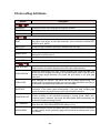
Printer setting definitions
Options
Description
LANGUAGE
Specify the printer menu language as English or Chinese.
EMULATION
Specify printer's control commands.
CHAR. MODE
Select ASCII or Chinese character mode.
FONT
Specify a kind of ASCII character font. If the print data contains font instruction,
the printer gives priority to print data instruction. (Only valid when CHARACTER
MODE is set to ASCII)
ENG PITCH
Specify the ASCII character spacing in characters per inch (cpi).
CHI PITCH
Specify the Chinese character spacing in characters per inch (cpi).
SLASH ZERO
Select the printing character for the zero character with a slash (/) or without, to
distinguish it from the letter O.
INTL CHAR SE
Specify the printer internal character set, utilizing international characters.
CHAR. SET
Specify character set as Italic Character or Graphic Character.
LINE SPACING
Specify the line spacing in lines per inch (lpi). If the print data includes vertical
pitch instruction, the printer will give priority to the print data instruction.
FORM LENGTH
Specify the page length of the form, for both cut sheet and continuous paper. The
printer feeds to next page according to the specified page length. If the print data
includes page length instruction, the printer will give priority to the print data
instruction.
FORM LOCK
After selecting this function, the printer will lock the page length setting. The
printer feeds to next page according to the current setting parameter and will not
be affected by the page length instruction of the print data.
PAGE SKIP
After selecting this function, the printer will leave one inch margin at the
perforation of the tractor paper automatically. If the print data includes page
margin instruction, the printer will give priority to print data instruction.
COMPRESS PRT
After selecting this function, the printer will print out transverse compressed
content according to the specified percentage in normal speed. When autocompress mode is selected, the printer will detect paper width automatically and
choose the proper percentage to print.
LEFT MARGIN
Specify the distance between paper left edge and printing home position. (Only
valid when ANY POSITION PAPER FEED function is on.)
BLACK MARK
After selecting this function, the printer will carry out black mark detect instruction
to make precise vertical positioning (paper/forms should have black mark on the
top surface).
- 26 -
PRINT DIR
Select the printing direction of the print head: unidirectional, bidirectional or Auto
selected via software.
HIGH DENSITY
After selecting this function, printing definition will be enhanced while the print
speed is reduce.
QUIET MODE
Disable or enable the low noise function. When this function is on, print speed will
be reduced.
AUTO LF
If this function is on, the printer will advance the paper one line automatically after
receiving every carriage return instruction.
LOADING
Specify the wait time between installing the cut sheet into the paper guide and
when it is fed into the printer. Choose to wait specify time or press LF/FF key to
feed paper.
EJECT
Specify paper eject direction when loading paper from front.
PIN SWITCH
After selecting this function, the printer will switch different pins to print table line
automatically.
MARGIN DETECT
After selecting this function, the printer will detect the paper edge automatically
after feeding paper, and start to print from the position according to the left margin
setting.
SKEW DETECT
After selecting this function, the printer will auto detect paper skew when feeding
cut sheet paper. If the slant degree is beyond the set parameter, the printer will
eject paper automatically.
BAUD RATE
Specify the printer serial data transfer rate.
PARITY
Specify the parity bit for serial data transfer.
DATA BITS
Specify the serial data bits.
STOP BITS
Specify the serial data transfer stop bit.
PROTOCOL
Specify the protocol of printer serial data transfer as software control (XON/XOFF)
or hardware control (DTR).
Select the broken pin. The printer will automatically replace it with other pin to
print.
- 27 -
Ethernet Interface Settings
NetFinder search
1.
Power on the printer, connect the LAN Ethernet cable to the printer port
located on the back of the printer. Verify the Ethernet port LED indicates
a normal connection.
Yellow LED
ON
OFF
2.
Green LED
Blink
OFF
Description
Connecting to network
Not connecting to network
Run NetFinder software (provided on CD shipped with the printer).
Button description:
Exit — Exit from the software
Search — Search for printers in the same LAN
Assign IP — Modify the IP address and other settings for the specified printer.
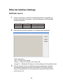
3.
Click the “Search” button, the dialog box appearing will begin searching
automatically listing printers found in the network. The time is counting
down in the progress bar (10 seconds) and the search will finish as soon
as the time is over.
- 28 -
Search results:
Model: Documax 5380
IP Address: 192.168.0.240 [Dynamic]
MAC Address: 20-2C-B7-00-3F-03
Should the printer not be found during the search, check to see if the
network firewall is blocking the search results. Temporally disable the
firewall and restart the NetFinder search.
In order to search and set the printer’s IP address conveniently for the
first time, the factory default setting is DHCP mode which assigns the IP
address dynamically. If there is no DHCP server in the connected LAN
and the printer is set to DHCP mode as well, then it will use the internal
pre-set address (IP: 10.0.0.1, Subnet Mask: 255.255.255.0)
automatically.
Setting printer static IP address
1.
Run NetFinder search. Refer to “NetFinder Search” section for
instructions.
- 29 -
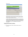
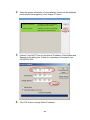
2.
Select the printer information to be modified by clicking on the displayed
printer (black frame appears), click “Assign IP” button.
Model: Documax 5380
IP Address: 192.168.0.140 [Dynamic]
MAC Address: 20-2C-B7-00-3F-03
Model: Accel 7450
IP Address: 192.168.0.120 [Dynamic]
MAC Address: 20-2C-B9-00-4F-04
3.
Uncheck “Use DHCP” and set the desired IP address, Subnet Mask and
Gateway in the dialog box. If there is no gateway in the network, use
255.255.255.255.
4.
Click “OK” button to assign Static IP address.
- 30 -
5.
Run NetFinder again to verify the printer has been updated with Static
IP.
Model: Documax 5380
IP Address: 192.168.0.240 [Static]
MAC Address: 20-2C-B7-00-3F-03
Model: Accel 7450
IP Address: 192.168.0.120 [Dynamic]
MAC Address: 20-2C-B9-00-4F-04
6.
7.
Exit NetFinder software.
8.
Right-click on the Documax 5380 icon
Properties”.
9.
Choose the “Ports” tab and select the correct IP interface port for your
printer.
10.
Open the “Devices and Printers” window from the PC Start button.
End of procedure.
- 31 -
and select “Printer
Diagnostic Testing
ASCII Self-test
1.
Power on the printer while pressing the ONLINE key.
Pressing the ONLINE key a second time will stop printing. Reboot the
printer to exit ASCII test mode.
ASCII TEST MODE
AMT Documax 5380
VX.X XXX XXXX/XX/XX
SN: XXXXXXXX
MAC: XX-XX-XX-XX-XX-XX DHCP: YES IP: 10.0.0.1 Subnet: 25
!"#$%&’( )*+-./0123456789:;<=>?@ABCDEFGHIJKLMNOPQRSTUVWXYZ[\]^_`abc
!"#$%&'( )*+-./0123456789:;<=>?@ABCDEFGHIJKLMNOPQRSTUVWXYZ[\]^_`abcd
"#$%&'( )*+-./0123456789:;<=>?@ABCDEFGHIJKLMNOPQRSTUVWXYZ[\]^_`abcde
Print head pin test
1.
2.
Power ON printer, load paper and then turn OFF the printer.
Press the ONLINE and LOAD/EJECT keys while turning on the printer.
Starting this test without paper preloaded will execute the Carriage Seek
test instead of Pin Test.
Hex dump mode
1.
Turn power on while pressing the LOAD/EJECT key to enter Hex Dump
mode. In this mode, the data sent from computer will print in
Hexadecimal code. Pressing the ONLINE key can stop printing, reboot
the printer to exit Hex Dump mode.
***** HEXADECIMAL DUMP *****
(0000) 1B 34 41 42 43 44 45 46 47 48 49 4A 4B 4C 4D 4E .4ABCDEFGHIJKLMN
(0010) 4F 50 51 52 53 54 55 56 57 58 59 5A 0D 0A 1B 35 OPQRSTUVWXYZ...5
(0020) 41 42 43 44 45 46 47 48 49 4A 4B 4C 4D 4E 4F 50 ABCDEFGHIJKLMNOP
(0030) 51 52 53 54 55 56 57 58 59 0D 0A
QRSTUVWXYZ..
- 32 -
Interface Specification
This Documax 5380 printer can be configured with 2.0 Full-Speed USB
interface, RS-232 serial interface, 10/100Base-T Ethernet interface or the
optional Centronics (IEEE1284 NIBBLE) parallel interface
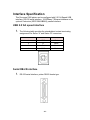
USB 2.0 full speed interface
1.
The following table provides the standardized contact terminating
assignments for Series “A” and Series “B” connectors.
Pin number
Name
Color
1
VBUS
Red
2
D-
White
3
D+
Green
4
GND
Black
14
23
Serial DB-25 interface
1.
RS-232 serial interface, printer DB-25 female type.
- 33 -
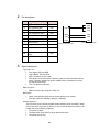
2.
Pin description:
Pin
Signal Name
Direction
1
FG Frame Ground
2
TXD Transmit Data
OUT
3
RXD Receive Data
IN
4
RTS Request to Send
DTR
DTR
CTS
OUT
5
CTS Clear to send
IN
6
DSR Data set ready
IN
7
GND Ground
8
DCD Data carrier Detect
6
DSR
DSR
1
DCD
8
DCD
2
0
GND
TXD
GND
RXD
7
CTS
5
2
3
2
3
TXD
GND
Printer 25TXD
PIN connector
GND
RXD
HOST 9 PIN connector
IN
…
…
DTR Data terminal
ready
20
OUT
…
…
3.
Signal description:
Typical pin out ~
Input signal: RXD and DSR
Output signal: TXD and DTR
RXD: The printer receives data
DTR: High level denotes that the printer is ready to receive the data from the
HOST; contrarily, denotes the printer is BUSY and it is forbidden to receive
the data from the HOST.
TXD: The printer sends data
Data bit format ~
Data bit is fixed 8 bits, Stop bit is fixed 1 bit
Baud Rate ~
Serial communication baud rate can be set through menu setting:
1200 bps, 2400 bps, 4800bps, 9600bps, 19200 bps
Interface Protocol ~
The DTR from printer controls the data stream between printer and HOST. When
DTR is high level, the printer is READY, it can receive the data from HOST. DTR
is high level in the following conditions:
The printer is online.
The data buffer of the printer is larger than limited value.
The printer has no error.
- 34 -
RXD
When the DTR is low level, the printer is BUSY, it cannot receive the data from
HOST. DTR is low level in the following conditions:
The printer is offline.
The data buffer of the printer is smaller than limited value.
The printer has an error.
X-ON/X-OFF Protocol ~
Send the X-ON (11H) code to the HOST from the printer through TXD, which
indicates the printer is FREE and can receive data from HOST. In the situation
where the printer buffer area is larger than limited value, the below two conditions
can make the printer send X-ON code:
The printer becomes FREE from BUSY state.
The printer becomes ONLINE from OFFLINE state.
Send the X-OFF (13H) code to the HOST from the printer through TXD, which
indicates the printer is BUSY and cannot receive data from HOST. In the
following five conditions, the printer sends X-OFF code to printer:
The printer becomes BUSY from FREE state.
The printer becomes OFFLINE from ONLINE state.
The printer buffer is smaller than limited value.
The printer has an error.
The printer is out of paper.
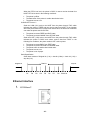
Serial Specification
Serial data consists of Original bit (1 bit) + data bit (8 bits) + check bit (1 bit) +
stop bit (1 bit).
Data bit
Original bit
D1
D2
D3
D4
D5
Ethernet interface
1.
10/100 Base-T:
- 35 -
Stop bit
D6
D7
D8
Check bit
Parallel interface
1.
Standard Centronics (IEEE1284 NIBBLE) parallel interface connector,
DB-36 pin type connector.
The parallel interface has the following characteristics:
Data format:
8-bit
Synchronization:
STROBE pulse
Handshaking:
BUSY and ACKNLG signals
Signal level:
TTL compatible
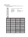
Signal Pin No.
Return Line Pin No.
Signal Name
Signal Direction
1
19
/STROBE
Printer ← Host
2~9
20 ~ 27
DATA
Printer ← Host
10
28
/ACK
Printer → Host
11
29
BUSY
Printer → Host
12
30
PE
Printer → Host
13
——
SELECT
Printer → Host
14
——
/AUTO FEED
Printer ← Host
15
——
NC
NC
16
——
SIGNAL GND
Printer ↔ Host
17
——
CHASSIS GND
Printer ↔ Host
18
——
+5V
Printer → Host
31
——
/PRIME
Printer ← Host
32
——
/ERROR
Printer → Host
33
——
SIGNAL GND
Printer ↔ Host
34
——
NC
Printer → Host
35
——
PULLED UP 5V
Printer → Host
36
——
/SELECT IN
Printer ← Host
- 36 -
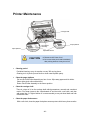
Printer Maintenance
Carriage shaft
Pinch Roller
Assembly
Paper platform
Paper platform
Paper feed sensor
CAUTION
Disconnect AC Power Cord
Do not touch the print head immediately
after printing because it may be too hot.
Cleaning period
Periodical cleaning: every six months or every 300 running hours.
Cleaning tool: dry cloth (use soft cloth to clean metal & plastic parts).
Clean the paper platform
Pull out the Pinch Roller Assembly and turn it over. Wipe away paper and ink debris.
Clean white pinch rollers with alcohol.
Return Pinch Roller Assembly to the former position.
Clean the carriage shaft
There is a layer of oil on the carriage shaft which guarantees a smooth and consistent
motion. First clean (remove) the contaminated oil and dust with a soft cloth, and then
add proper lube (3-1 light machine oil is recommended), move print head back and forth
to distribute lube.
Clean the paper feed sensors
With a soft cloth, clean the paper feed photo sensors protect shield every three months.
- 37 -
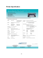
Printer Specification
- 38 -