1
ES900
USER'S MANUAL
1
This unit complies with the Low Voltage Directive 73/23/EEC and the
EMC Directive 89/336/EEC.
This device complies with Part 15 of the FCC Rules. Operation is
subject to the following two conditions: (1) this device may not cause
harmful interference, and (2) this device must accept any interference
received, including interference that may cause undesired operation.
1. The details of this User's Manual are subject to change without previous notification.
2. This User's Manual has been prepared with the utmost care to cover all aspects of the time
recorder's use.
If you feel, however, that some explanations are inadequate, unclear, or difficult to
understand, please do not hesitate to contact Acroprint.
3. No part of this publication may be reproduced, stored in a retrieval system, or transmitted,
in any form or by any means, mechanical, photocopying, recording or otherwise without
the written consent of Acroprint Time Recorder.
ALL RIGHTS RESERVED
©2003 ACROPRINT TIME RECORDER
2
TABLE OF CONTENTS
1. INTRODUCTION & FEATURES
2. BEFORE USING YOUR TIME RECORDER
Attached Accessories
Location of Name
Print Position on Time Card
3.
4.
5.
6.
7.
8.
9.
10.
11.
12.
13.
14.
15.
QUICK EASY SETUP
OPTIONAL FUNCTIONS
HOW TO PROGRAM THE TIME RECORDER
SETTING THE TIME
SETTING THE DATE
SETTING THE 12/24 HOUR FORMAT
SETTING THE PRINT ORDER
SETTING YEAR AND MINUTE FORMAT
SETTING THE PRE-PROGRAMED COMMENTS
SETTING THE CUSTOMIZED COMMENTS
SETTING THE LANGUAGE
SETTING THE PRINT METHOD
SETTING THE DAYLIGHT SAVING TIME
16.
17.
18.
19.
20.
21.
SETTING THE NUMBER
SETTING THE INITIAL NUMBER
SETTING THE TIME TABLE PROGRAM
SETTING THE EXTERNAL TIME SIGNAL / BUILT-IN BUZZER
SETTING THE SLAVE CLOCK
SETTING THE PASSWORD
Deleting the Daylight Saving Time settings
How to change settings when the Password is set
Canceling the Password
22.
23.
24.
25.
26.
27.
RE-SETTING
WALL MOUNTING
REPLACING THE RIBBON CASSETTE
CHARACTER CODE FOR ALPHANUMERIC
INSTALLING THE Ni-Cd BATTERY (OPTIONAL)
CONNECTING THE OPTIONAL FUNCTIONS
Connecting the Master Clock
Connecting the External Time Signal
Attaching the Wire Clamp
28. TROUBLE-SHOOTING
29. SPECIFICATIONS
2
3
3
3
3
4
5
6
7
8
9
10
11
13
14
22
23
25
28
29
31
32
39
40
41
42
43
44
45
46
48
52
53
53
54
55
56
57
3
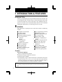
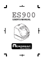
1. INTRODUCTION & FEATURES
INTRODUCTION:
Thank you for purchasing an Acroprint Model ES900 Time Recorder. We
are confident this time recorder will give you full satisfaction. Items such
as the time and date are preset at the factory. After plugging in the AC
power, the recorder can be used immediately. However, we recommend
reading this manual before you start using your time recorder.
FEATURES:
Main applications : Payroll/job cost recorder, time recorder or numbering
machine.
The Quartz Time Recorder
Dot-matrix printer
Perpetual calendar
Automatic daylight saving time
4-way print activation
Automatic
Manual
Semi-automatic
Combination
Adjustable print position
Prints in 7 languages
Prints numbers/date
Time table program
I Mark© printing (Irregular
registration Mark)
•
•
•
•
•
•
•
•
•
•
•
•
•
•
•
•
•
•
•
•
•
•
•
•
•
•
•
•
•
•
•
•
•
•
•
•
•
•
13 pre-programmed comments
Alphanumeric printing
Selectable 4-digit year imprint
12 or 24-hour format
Regular minute, tenths,
twentieths, or hundredths of
an hour
Password for program protection
Digital LCD (Date, Hour,
Minute, Day of the week
indication)
Wall or desktop mount
Full power reserve (optional)
Built-in buzzer (optional)
External time signal (optional)
Caution:
Do not use in places:
• Subject to high humidity and dust.
• Exposed to strong or continuous vibrations.
• Exposed to direct sunlight.
• The temperature range in which all functions of the ES900 will operate
correctly is from 23˚F to 113˚F (-5˚C to 45˚C). Be sure to place and use
your time recorder only in locations in which this temperature range is
not exceeded and there are no sharp temperature variations.
Daily Care
For cleaning, turn the power off and wipe the case clean of dust and dirt with a dry
cloth.
2
2
4
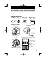
2. BEFORE USING YOUR RECORDER
Package Contents
Unpack the time recorder and check its contents to ensure that the time
recorder unit and all accessories shown below are included.
Attached Accessories
• User's Manual
• Keys
................2 pcs.
• Wall-Mount Fittings
Screw
.......4 pcs.
Template ....1 sheet.
• Ribbon Cassette
................1 pc.
• The ribbon cassette is
installed at the factory.
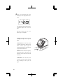
Location of Name
<Back view>
<Front view>
Key hole
Display
Cover
Wall-mount holes
AC power plug
(230VAC model)
Push bar
Print Position on Time Card
<Cover off>
<Print position adjuster>
Display
JAN 31 12:00
3
30 mm
Ribbon cassette
15 mm
Print head
JAN 31 12:00
JAN 31 12:00
Control buttons
Print position from the
card edge is adjustable
by pressing and sliding
the print position
button located on the
right outside bottom of
the recorder.
Maximum
distance
from edge of form to
print is approximately
1 3/16" (30 mm).
32
5
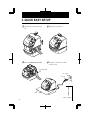
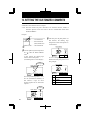
3. QUICK EASY SETUP
1 Unlock the key and remove the top
3 Replace the cover and lock.
case.
CA
U
TI
ON
2 Remove the PROTECTION PAD.
4 Plug the AC cord into the AC outlet
and insert a card.
Protection PAD
AC outlet
AC cord
CA
Card
ION
JAN 31 12:00
UT
(Print example)
4
2
6
4. OPTIONAL FUNCTIONS
The following optional functions are available by adding an optional board:
External Time Signal for Bell, Built-in Buzzer, and the Slave Clock.
External Time Signal and Built-in Buzzer
External time signal and Built-in buzzer shall be controlled by time table program and their
duration settings.
Refer to the "18. SETTING THE TIME TABLE PROGRAM," and the "19. SETTING THE
EXTERNAL TIME SIGNAL / BUILT-IN BUZZER."
Connection Specifications for External time signal contact
• Contact output: dry contact
• Contact capacity: 5A, 30VDC (Resistive)
The Slave Clock
The Slave Clock is a function to synchronize the time of the time recorder and the master clock.
This function operates by choosing Slave Clock by Slave Clock setup.
Refer to the "20. SETTING THE SLAVE CLOCK."
Input signal Specifications.
• 30-second reversal.
Since the 30-second signal (-V side) is not received, the difference from the master clock is 30
seconds or more, and the time is not modified correctly.
• 60-second reversal.
Since the odd-numbered signal (-V side) is not received, the difference from the master clock is
one minute or more, and the time is not modified correctly.
• 59-minute impulse ( 2-wire )
From the 59th minute through the 49th minute the pulse is transmitted with line AB positive with
respect to PC.
From the 50th minute to the 59th minute the pulse is transmitted with line AB negative with
respect to PC.
During the 59th minute, the continuous pulse of 20 times is transmitted with line AB negative
with respect to PC.
As this method monitors from 5 minutes before several preset hours to input 0-minute signal,
more than 5 minutes of tolerance for a master clock can not compensate time correctly.
Pulse Specification
Pulse width
Voltage
Input sensitivity
0.1 second or more
6 - 32V
5
7
5. HOW TO PROGRAM THE TIME RECORDER
To enter the program setting mode, you must plug the AC cord into the AC outlet and remove
the cover. Next press the [SELECT] button once. Then the recorder changes into the program
mode showing the " "on the display positioned under the "TIME" mark.
N/A
Program modes
Control buttons
Function of 3 control buttons
[SELECT]: You can select the desired program setting mode by pressing this [SELECT]
button. Selected program setting mode is indicated by the " " on the display.
[CHANGE]: When you press the [CHANGE] button, you can increment the set value.
[SET]:
You can set the value selected on the display by pressing the [SET] button.
Thereafter you press this [SET] button again, you can return the Time
recorder to the normal operation mode.
6
2
8
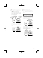
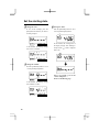
6. SETTING THE TIME
Example: Change the time from 10:08 to 10:09.
1 Press the [SELECT] button and position
the " " under the "TIME" mark.
At that moment, the "Hour" flashes.
(The flashing means it can be changed.)
2 Change the "Minute".
Press the [CHANGE] button to set at
"09". And then press the [SET] button.
TIME
Second
TIME
Hour
Minute
SELECT
SELECT
CHANGE
SET
CHANGE
SET
At that moment, the "Second" starts to
run from "00".
Change the "Hour".
In case of the example, press the
[SET] button because the hour is not
being changed.
TIME
3 After you finish setting the time, press
the [SET] button once again.
SELECT
CHANGE
SET
SU
MO
TU
WE
TH
FR
SA
At that moment, the flashing changes
from "Hour" to "Minute".
Now the time setting has been
completed. Replace the cover and
lock.
Important: Printing will not occur
unless Step 3 is completed.
3
7
9
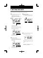
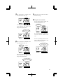
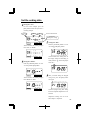
7. SETTING THE DATE
Example: Change the date from October 20, 2003 to October 21, 2003.
1 Press the [SELECT] button and position
the " " under the "DATE" mark.
At that moment, the "Year" flashes. (The
flashing means it can be changed.)
3 Change the "Date".
Press the [CHANGE] button to set at
"21". And then press the [SET] button.
DATE
Year
DATE
Month
Date
SELECT
SELECT
CHANGE
CHANGE
SET
SET
Change the "Year".
In case of the example, press the
[SET] button because the year 2003
does not need to be changed.
DATE
SELECT
CHANGE
SET
At that moment, the flashing changes
from "Year" to "Month".
4 After you finish setting the date, press
the [SET] button once again.
SU
MO
TU
WE
TH
FR
SA
2 Change the "Month".
In case of the example, press the
[SET] button because the month is not
being changed.
DATE
Now the date setting has been
completed. Replace the cover and
lock.
Important: Printing will not occur
unless Step 4 is completed.
SELECT
8
CHANGE
SET
At that moment, the flashing changes
from "Month" to "Date".
6
10
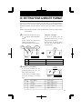
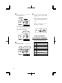
8. SETTING THE 12/24 HOUR FORMAT
Example: Change the hour format to 24 hour.
1 Press
the [SELECT] button and
position the " " under the "HOUR"
mark.
At that moment, the flashing digit
indicates "Hour Display Format
Options". (The flashing means it can be
changed.)
Change the "Hour".
In case of the example, press the
[CHANGE] button to set at "2". Then
press the [SET] button.
HOUR
HOUR
SELECT
CHANGE
SET
SELECT
Hour Display Format Options
Display
1.
12 hour
PM 3:00
2.
24 hour
15:00
CHANGE
SET
2 After you finish setting the 12/24 hour
format, press the [SET] button once
again.
SU
MO
TU
WE
TH
FR
SA
Now the 12/24 hour setting has been
completed. Replace the cover and
lock.
Important: Printing will not occur
unless Step 2 is completed.
3
9
11
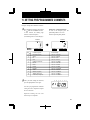
9. SETTING THE PRINT ORDER
Example: Set the print order to "Month, Date, Year, Hour, Minute."
1 Press the [SELECT] button and position
the " " under the "PRINT ORDER" mark.
At that moment, the flashing digit
indicates "Print Order Options."
(The flashing means it can be changed.)
Change the "Print Order Options".
In case of the example, press the
[CHANGE] button to set at "3". Then
press the [SET] button.
PRINT ORDER
SELECT
PRINT ORDER
CHANGE
SET
SELECT
CHANGE
SET
Y=Year, M=Month, D=Date, DOW=Day of the week, H=Hour, Min=Minute, S=Second
C=Comment, N=Number
Print Order Options
1.
2.
3.
4.
5.
6.
7.
8.
9.
10.
11.
12.
13.
14.
15.
M.D.H.Min
D.M.H.Min
M.D.Y.H.Min
D.M.Y.H.Min
Y.M.D.H.Min
Y.M.D.H.Min.S
D.H.Min
DOW.D.H.Min
Y.M.D
M.D
DOW.D.M.Y
C.M.D.Y
C.D.M.Y
C.Y.M.D
M.D.Y.C
Print Example
16.
17.
31 JAN 10:00
18.
JAN 31 '03 10:00
19.
31 JAN '03 10:00
20.
'03 JAN 31 10:00
'03 JAN 31 10:00:00 21.
22.
31 10:00
23.
FR, 31 10:00
24.
'03 JAN 31
JAN 31
25.
FR, 31 JAN '03
26.
SENT JAN 31 '03
27.
SENT 31 JAN '03
28.
SENT '03 JAN 31
29.
JAN 31 '03 SENT
30.
JAN 31 10:00
2 After you finish setting the print order,
Print Order Options
Print Example
D.M.Y.C
31 JAN '03 SENT
Y.M.D.C
'03 JAN 31 SENT
C.D.H.Min
SENT 31 10:00
N.M.D.Y
000123 JAN 31 '03
N.D.M.Y
000123 31 JAN '03
N.Y.M.D
000123 '03 JAN 31
M.D.Y.N
JAN 31 '03 000123
D.M.Y.N
31 JAN '03 000123
Y.M.D.N
'03 JAN 31 000123
N.D.H.Min
000123 31 10:00
N.M.D.H.Min
123 JAN 31 10:00
N.Y.M.D.H.Min
123 '03 JAN 31 10:00
N.Y.M.D.H.Min.S
123 '03 JAN 31 10:00:00
N
000123
Customaized Comments
SU
MO
TU
WE
TH
FR
SA
press the [SET] button once again.
Now the print order setting has been
completed. Replace the cover and
lock.
Important: Printing will not occur
unles Step 2 is completed.
10
9
12
10. SETTING YEAR & MINUTE FORMAT
If you have selected the recorder to print the year, this allows you to choose the number of
digits in the year (two or four). You may also select the minute format: standard minutes,
hundredths, twentieths or tenths of an hour. You may also choose whether to print leading
zeros.
Example: Change the Year imprint to 4 digits and the Minutes to 1/100 min. and the Leading
Zero to enabled.
1 Press the [SELECT] button and position
the " " under the "PRINT PATTERN"
mark.
At that moment, the flashing digit
indicates "Year Digit Options".
(The flashing means it can be changed.)
Year
Digit
Type of
Minute
SELECT
PRINT
PATTERN
CHANGE
Change the "Year Digit".
In case of the example, press the
[CHANGE] button to set at "2". And
then press the [SET] button.
At that moment, the flashing changes
from the "Year Digit Options" to
"Type of Minute".
Leading
Zero
SET
PRINT
PATTERN
SELECT
Year Digit Options
Print Example
1.
2 Digits
JAN 31 '03 10:00
2.
4 Digits
JAN 31 2003 10:00
2 Change the "Type of Minute".
In case of the example, press the
[CHANGE] button to set at "2". And
then press the [SET] button.
At that moment, the flashing changes
from "Type of Minute" to "Leading
Zero".
3
CHANGE
SET
PRINT
PATTERN
SELECT
CHANGE
Type of Minute
Print Example
1.
1/60 Min.
JAN 31 2003 10:10
2.
1/100 Min.
JAN 31 2003 10.17
3.
1/20 Min. (= 5/100 Min.)
JAN 31 2003 10.15
4.
1/10 Min.
JAN 31 2003 10.1
SET
11
13
PRINT
PATTERN
3 Change the "Leading Zero".
In case of the example, press the
[CHANGE] button to set at "2". And
then press the [SET] button.
SELECT
CHANGE
Leading Zero
Print Example
1.
ZERO Disabled
JAN 1 3:00
2.
ZERO Enabled
JAN 01 03:00
4 After
you finish setting the print
pattern, press the [SET] button once
again.
SU
MO
TU
WE
TH
SET
FR
SA
Now the print pattern setting has been
completed. Replace the cover and
lock.
Important: Printing will not occur
unless Step 4 is completed.
12
10
14
11. SETTING PRE-PROGRAMMED COMMENTS
Example: Change the comment to "SENT".
1 Press the [SELECT] button and position
the " " under the "COMMENT" mark.
At that moment, the flashing digit
indicates "Comment Options".
(The flashing means it can be changed.)
Change the "Comment Options".
In case of the example, press the
[CHANGE] button to set at "2".
And then press the [SET] button.
COMMENT
SELECT
1.
2.
3.
4.
5.
6.
7.
8.
9.
10.
11.
12.
13.
CHANGE
SET
COMMENT
SELECT
CHANGE
Comment Options
Print Example
RCVD (Received)
SENT
IN
OUT
CFMD (Confirmed)
FILED
PAID
USED
FAXED
VOID
ORIGN (Original)
APR'D (Approved)
CMPL'D (Completed)
JAN 31 '03 RCVD
JAN 31 '03 SENT
JAN 31 '03 IN
JAN 31 '03 OUT
JAN 31 '03 CFMD
JAN 31 '03 FILED
JAN 31 '03 PAID
JAN 31 '03 USED
JAN 31 '03 FAXED
JAN 31 '03 VOID
JAN 31 '03 ORIGN
JAN 31 '03 APR'D
JAN 31 '03 CMPL'D
2 After you finish setting the comment,
SU
MO
TU
WE
TH
SET
FR
SA
press the [SET] button once again.
Now the pre-programmed comments
setting has been completed. Replace
the cover and lock.
Important: Printing will not occur
unless Step 2 is completed.
11
13
15
12. SETTING THE CUSTOMIZED COMMENTS
• Maximum 3 lines comment can be set to print.
• Note: This time recorder can print a maximum of 31 characters. However, number of
characters depends on font size. Refer to the "25. CHARACTER CODE FOR
ALPHANUMERIC".
Example:
space
ABC HOTEL ......... 1st comment line
21 OCT '03 ........... 2nd comment line
(Date, Month, Year)
BOSTON, MA ....... 3rd comment line
2 And then press the [SET] button. At
that moment, the flashing digit
changes from "Print Order Options" to
"Print Position".
PRINT ORDER
1
Press the [SELECT] button and position
the " " under the "PRINT ORDER"
mark.
At that moment, the flashing digit
indicates "Print Order Options".
(The flashing means it can be changed.)
SELECT
CHANGE
SET
In case of example, press the [SET]
button because the print position is not
being changed.
Print
Order Options
PRINT ORDER
PRINT ORDER
SELECT
SELECT
CHANGE
CHANGE
SET
SET
Press the [CHANGE] button to set at
the "30" (Customized Comments). At
that moment, a digit for "Print
Position" appears next to "Print Order
Options".
Print Position
1.
Align Left
2.
Center
3.
Align Right
Print
Position
PRINT ORDER
SELECT
14
CHANGE
SET
13
16
3 Press the [SELECT] button and position
the " " under the "COMMENT" mark.
Setting the 1st comment line.
At the moment, the flashing digit
indicates "Character Position". And then
press the [SET] button.
Comment
Line
Character
Position
Character
Code
COMMENT
4 Set the "Character Code"
In case of example, the 1st character is
"A", then enter the character code
"02".
Refer to the "25. CHARACTER
CODE FOR ALPHANUMERIC"
Press the [CHANGE] button until the
correct character code appears. And
then press the [SET] button.
The character code
"02" means "A".
SELECT
CHANGE
SET
At the moment, the flashing changes
from "Character Position" to "Character
Code".
COMMENT
SELECT
CHANGE
SET
SELECT
SET
At that moment, the "Character
Position" changes from the 1st
character to the 2nd character.
The 2nd
Character
SELECT
14
CHANGE
COMMENT
CHANGE
SET
15
17
5 The 2nd character is "B", then enter
the character code "03".
7 Follow the same procedure for further
characters settings.
COMMENT
8 Setting the 2nd comment line
Press the [SET] button to change the
comment line number to "C2".
SELECT
CHANGE
SET
Press the [CHANGE] button until the
correct character code appears. And
then press the [SET] button.
The character code
"03" means "B".
The 2nd
comment line
SELECT
COMMENT
CHANGE
SET
In case of example, the 1st character is
"DATE", then enter the character code
"28".
SELECT
CHANGE
SET
6 The 3rd character is "C", then enter
Press the [CHANGE] button until the
correct character code appears. And
then press the [SET] button.
the character code "04".
The 3rd
character
The character code
"28" means "DATE".
COMMENT
SELECT
SELECT
CHANGE
CHANGE
SET
SET
Press the [CHANGE] button until the
correct character code appears. And
then press the [SET] button.
The character code
"04" means "C".
SELECT
16
CHANGE
SET
14
18
9 The 2nd character is "SPACE", then
11
enter the character code "01".
Follow the same procedure for further
characters settings.
COMMENT
12
SELECT
CHANGE
Setting the 3rd comment line.
Press the [SET] button to change the
comment line number to "C3".
SET
Press the [CHANGE] button until the
correct character code appears. And
then press the [SET] button.
The character code
"01" is "SPACE".
The 3rd
comment line
SELECT
COMMENT
CHANGE
SET
In case of example, the 1st character is
"B", then enter the character code
"03".
SELECT
10
CHANGE
SET
The 3rd character is "MONTH", then
enter the character code "27".
The 3rd
character
Press the [CHANGE] button until the
correct character code appears. And
then press the [SET] button.
The character code
"03" means "B".
COMMENT
SELECT
SELECT
CHANGE
CHANGE
SET
SET
Press the [CHANGE] button until the
correct character code appears. And
then press the [SET] button.
The character code"27"
means "MONTH".
SELECT
15
CHANGE
SET
17
19
13
The 2nd character is "O", then enter
the character code "10".
The 2nd
character
SELECT
COMMENT
CHANGE
SET
15
After you finish setting the customized
comments, press the [SET] button
three times.
Now the customized comments setting
has been completed. Replace the cover
and lock.
Important: Printing will not occur
unless Step 15 is completed.
Press the [CHANGE] button until the
correct character code appears. And
then press the [SET] button.
SU
MO
TU
WE
TH
FR
SA
The character code
"10" means "O".
SELECT
CHANGE
SET
HOW TO CORRECT
CUSTOMIZED COMMENTS
Use below code number correction.
14
Set the last character "A" in the same
manner as above.
The 10th
character
SELECT
18
The character code
"02" means "A".
CHANGE
SET
Code
Meaning
F8
Insert Character
F9
Delete Character
FA
Insert Line
Fb
Delete Line
FC
Exchange Line 1 to 2
Fd
Exchange Line 2 to 3
FE
Exchange Line 1 to 3
FF
Delete All
16
20
Setting the Print Position of Customized Comments
Align Left
Center
ABC HOTEL
21 OCT '03
BOSTON, MA
Align Right
ABC HOTEL
21 OCT '03
BOSTON, MA
ABC HOTEL
21 OCT '03
BOSTON, MA
Example: Change the print position to "Center".
1 Press the [SELECT] button and position
the " " under the "PRINT ORDER"
mark.
At that moment, the flashing digit
indicates "Print Order Options".
(The flashing means it can be changed.)
PRINT ORDER
2 Change the "Print Position"
In case of example, press the
[CHANGE] button to set at "2". And
then press the [SET] button.
PRINT ORDER
Print Order
Options
SELECT
CHANGE
SET
3 After you finish setting the print order
SELECT
CHANGE
SET
In case of the example, press the
[SET] button because the "Print Order
Options" are not to be changed. At that
moment, the flashing digit indicates
"Print position".
Print
Position
PRINT ORDER
and the print position, press the [SET]
button once again.
SU
MO
TU
WE
TH
FR
SA
Now the print order and the print
position settings have been completed.
Replace the cover and lock.
Important: Printing will not occur
unless Step 3 is completed.
SELECT
CHANGE
SET
Print Position
18
1.
Align Left
2.
Center
3.
Align Right
19
21
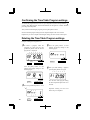
Confirming and Changing the Customized Comments
Example: 1st comment line: No change.
2nd comment line: Change from "Year" to time "HH:MM".
3rd comment line: No change.
ABC HOTEL Year
21 OCT '03
BOSTON, MA
1 Confirming the 1st comment line
To confirm the customized comments that
have been set, press the [SELECT] button
and position the " " under the "PRINT
ORDER" mark. At that moment, the
"Character Position" flashes, and press the
[CHANGE] button.
ABC HOTEL
21 OCT 10:03
BOSTON, MA
Time
At that moment, the display changes
to the following figure.
"00" means
"NULL"
COMMENT
While the "Character Position" changes,
the "Character Code" that has been set
appears.
Comment
Line
SELECT
SELECT
Character
Position
Character
Code
COMMENT
CHANGE
SET
CHANGE
SET
At this time, press the [SET] button
twice, and the 2nd comment line is
displayed.
The 2nd
comment line
COMMENT
COMMENT
SELECT
SELECT
CHANGE
CHANGE
SET
SET
The last
character code
SELECT
20
CHANGE
SET
After confirming the last character
code of the 1st comment line, press
the [CHANGE] button once again.
18
22
2 Changing the Customized Comments
In case of example, press the
[CHANGE] button to set at "5". And
then press the [SET] button. At that
moment, flashing changes from the
"Character Position" to the
"Character Code".
The character code
"26" means "Year".
COMMENT
SELECT
CHANGE
Character
Position
1
Code
28
Meaning
Date
2
3
4
01
27
01
5
26
SPACE Month SPACE
Year
SET
Press the [CHANGE] button to set at
"2A".
The character code
"2A" means HH:MM"
COMMENT
SELECT
CHANGE
Character
Position
1
Code
28
Meaning
Date
2
3
4
5
01
27
01
2A
SPACE Month SPACE HH:MM
SET
Then press the [SET] button once.
Now changing the character code has
been completed.
3 Confirming the 3rd comment line
Confirm the 3rd comment line in the
same manner as Step 1.
4 After
you finish confirming and
changing the customized comments,
press the [SET] button once again.
SU
MO
TU
WE
TH
FR
SA
Now confirming and changing the
customized comments have been
completed. Replace the cover and
lock.
Important: Printing will not occur
unless Step 4 is completed.
19
21
23
13. SETTING THE LANGUAGE
This setting is available if you select "Month", "Day of the week" or "Comment" in
previous "PRINT ORDER".
Example: Change the print language into Spanish.
1 Press the [SELECT] button and position
the " " under the "LANGUAGE" mark.
At that moment, the flashing digit
indicates "Print Language Options".
(The flashing means it can be changed.)
Change the "Language".
In case of the example, press the
[CHANGE] button to set at "2".
And then press the [SET] button.
LANGUAGE
SELECT
CHANGE
SET
LANGUAGE
SELECT
CHANGE
Print Language Options
Print Example
1.
ENGLISH
TH, 25 DEC '03
OUT 31 10:00
2.
SPANISH
JU, 25 DIC '03
SAL 31 10:00
3.
GERMAN
DO, 25 DEZ '03
AUSG 31 10:00
4.
FRENCH
JE, 25 DEC '03
SORT 31 10:00
5.
ITALIAN
GI, 25 DIC '03
USC 31 10:00
6.
PORTUGUESE
QI, 25 DEZ '03
SAIDA 31 10:00
7.
NUMERIC
4, 25-12 '03
OUT 31 10:00
2 After you finish setting the language,
SU
MO
TU
WE
TH
SET
FR
SA
press the [SET] button once again.
Now the language setting has been
completed. Replace the cover and
lock.
22
Important: Printing will not occur
unless Step 2 is completed.
20
24
14. SETTING THE PRINT METHOD
Example: Change the print direction to "Left" and the print activation to "Manual".
1 Press the [SELECT] button and position
the " " under the "PRINT METHOD"
mark.
At that moment, the flashing digit
indicates "Print Direction Options".
(The flashing means it can be changed.)
Print
direction
SELECT
Change the "Print Direction".
In case of the example, press the
[CHANGE] button to set at "2".
And then press the [SET] button.
At that moment, the flashing changes
from the "Print Direction" to the "Print
Activation".
Print
method
PRINT
METHOD
CHANGE
SET
PRINT
METHOD
SELECT
CHANGE
SET
Print Direction Options
1.
Right-hand margin of form
2.
Left-hand margin of form
2 Change the "Print Activation".
In case of the example, press the
[CHANGE] button to set at "3".
And then press the [SET] button.
PRINT
METHOD
SELECT
CHANGE
SET
Print Activation Options
21
1.
Automatic
2.
Semi-automatic
3.
Manual
4.
Combination
23
25
3 After
you finish setting the print
method, press the [SET] button once
again.
SU
MO
TU
WE
TH
FR
SA
Now the print method setting has been
completed. Replace the cover and
lock.
Important: Printing will not occur
unless Step 3 is completed.
Automatic will allow the clock to print
by simply inserting a card or piece of
paper.
Semi-automatic will allow the clock
to print by pressing the push bar only
when a card or piece of paper is
inserted. (Will print only when the card
or paper reaches the sensor.)
Manual will allow the clock to print by
pressing the push bar. (Will print even
when the card or form does not reach
the sensor.)
Push bar
Combination will allow the time
recorder to print by pressing the push
bar or inserting a card or piece of
paper.
24
22
26
15. SETTING DAYLIGHT SAVING TIME
Daylight Saving Time function
1 D.S.T. execution time
At 2:00 a.m. on the first day of Daylight Saving Time, the clock
automatically gains one hour to show 3:00 a.m.
When 3:00 a.m. comes on the last day of the Daylight Saving Time,
it loses one hour and returns to 2:00 a.m.
2 Setting D.S.T.
Example:
Start date Sunday, April 6, 2003
End date Sunday, October 26, 2003
If set as the above, the unit remembers the start date as the first
Sunday in April and the end date as the last Sunday in October.
Once set, the unit automatically updates the settings every year
thereafter. No further manual setting is necessary.
Example
The setting for daylight saving time will be
described using the following example.
Today (present day)
Wednesday, January 29, 2003
Starting date of daylight
saving time
Sunday, April 6, 2003
The first Sunday in April
Ending date of daylight
saving time
Sunday, October 26, 2003
The last Sunday in October
1 Press the [SELECT] button and position the "
" next to the "DAYLIGHT SAVING
TIME" mark. (The flashing means it can be changed.)
Year
Month
SELECT
23
CHANGE
Date
SET
DAYLIGHT SAVING TIME
" " mark means
"starting date" setting
25
27
Set the starting date.
2 Change the "Year"
4 Change the "Date"
In case of the example, press the
[SET] button because the year 2003 is
not being changed.
SELECT
CHANGE
SET
At the moment, the flashing changes
from "Year" to "Month".
Push the [CHANGE] button to set at
"06" and push the [SET] button.
SU
At the moment, the "starting date" of
the display changes from flashing to
steady and the " " mark is displayed
under "SU".
SU
SELECT
CHANGE
SET
3 Change the "Month"
SU
MO
TU
WE
TH
FR
SA
Push the [CHANGE] button to set at
"4" and push the [SET] button.
SELECT
CHANGE
SET
After a few seconds, go on to the
"set the ending date".
Please see the following page.
At the moment, the flashing changes
from "Month" to "Date".
SELECT
26
CHANGE
SET
24
28
Set the ending date.
5 Change the "Year"
In case of the example, press the
[SET] button because the year 2003 is
not being changed.
Year
Month
Date
DAYLIGHT SAVING TIME
" " mark means
"ending date" setting
SELECT
CHANGE
SET
At the moment, the flashing changes
from "Year" to "Month".
SELECT
CHANGE
SET
6 Change the "Month"
Push the [CHANGE] button to set at
"10" and push the [SET] button.
SELECT
CHANGE
SET
At the moment, the flashing changes
from "Month" to "Date".
7
Change the "Date"
Push the [CHANGE] button to set at
"26" and push the [SET] button.
SU
At the moment, the "ending date" of
the display changes from flashing to
steady and the " " mark is displayed
under "SU".
SU
8 After you finish setting the daylight
saving time, press the [SET] button
once again.
SU
SELECT
25
CHANGE
SET
MO
TU
WE
TH
FR
SA
Now the daylight saving time setting
has been completed. Replace the cover
and lock.
Important: Printing will not occur
unless Step 8 is completed.
27
29
Deleting the Daylight Saving Time settings
To delete and cancel the daylight saving time settings, change the display of "Month" of the
starting setting to " ".
Example: To change April 6, 2003 as the "starting date" and delete daylight saving time
settings.
1 Press the [SELECT] button and position
the "
" next to the "DAYLIGHT
SAVING TIME" mark.
(The flashing means it can be changed.)
Year
Month
3
Press the [CHANGE] button to set at
" ".
SU
DAYLIGHT
SAVING TIME
SU
Press the [SET] button twice. This
cancels the daylight saving time
settings.
SELECT
CHANGE
SET
2 Press the [SET] button and the flashing
changes from "Year" to "Month".
SU
4 After you finish deleting the daylight
saving time, press the [SET] button
once again.
SU
SELECT
CHANGE
MO
TU
WE
TH
FR
SA
SET
Deleting the daylight saving time has
been completed. Replace the cover
and lock.
Important: If you do not complete
Step 4, the time recorder will not
print.
28
26
30
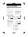
16. SETTING THE NUMBER
In this setup, you can select digits of printed number, the Repeat Times of number, and type
of Number Reset .
Example: Change the Number Digit to 4 digits and the Repeat Times to 2 times, and the
Reset to 0.
1 Press the [SELECT] button and position
Change the "Number Digit".
The Number Digit can be set to 1 to 8.
In case of the example, press the
[CHANGE] button to set at "4". And
then press the [SET] button.
At that moment, the flashing changes
from the "Number Digit" to "Repeat
Times".
the " "next to the "NUMBER" mark.
At that moment, the flashing digit
indicates "Number Digit".
(The flashing means it can be changed.)
Number
Digit
Repeat
Times
Reset
Options
NUMBER
SELECT
CHANGE
SET
NUMBER
SELECT
CHANGE
123456 JAN 31 '03
1234 JAN 31 '03
Print Example: 6 Digits of Number
4 Digits of Number
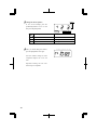
2 Change the "Repeat Times".
The Repeat Times can be set to 0 to 9.
In case of the example, press the
[CHANGE] button to set at "2". And
then press the [SET] button.
At that moment, the flashing changes
from "Repeat Times" to "Reset
Options".
Print Example: 0 time repeat
Note: If the recorder is set to
repeat 0 times, the number will
not advance.
2 times repeat
27
SET
NUMBER
SELECT
CHANGE
(1st time)
(2nd time)
(3rd time)
(4th time)
(5th time)
123456 JAN 31 '03
123456 JAN 31 '03
123456 JAN 31 '03
123456 JAN 31 '03
123456 JAN 31 '03
(1st time)
(2nd time)
(3rd time)
(4th time)
(5th time)
123456 JAN 31 '03
123456 JAN 31 '03
123457 JAN 31 '03
123457 JAN 31 '03
123458 JAN 31 '03
SET
29
31
3 Change the "Reset Options".
NUMBER
In case of the example, press the
[CHANGE] button to set at "3". And
then press the [SET] button.
SELECT
Reset Options
CHANGE
Execution event of Reset.
1.
Disabled
2.
Return to INITIAL NUMBER
Change of date
3.
Return to 0
Change of date
4 After you finish setting the number,
SET
SU
MO
TU
WE
TH
FR
SA
press the [SET] button once again.
Now the number setting has been
completed. Replace the cover and
lock.
Important: Printing will not occur
unless Step 4 is completed.
30
28
32
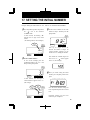
17. SETTING THE INITIAL NUMBER
Example: Setting the initial number to "123". Refer to "16. SETTING THE NUMBER".
1 Press the [SELECT] button and position
3 Set the correct numbers in the same
the "
" next to the "INITIAL
NUMBER" mark.
At that moment, the flashing " "
indicates the 1st digit of the initial
number.
(The flashing means it can be changed.)
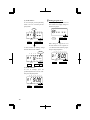
manner as Step 2. And then press the
[SET] button.
The 1st
digit
INITIAL
NUMBER
INITIAL
NUMBER
SELECT
CHANGE
SET
Note: Up to 8 digits can be set,
however the number of digits for
"Initial Number" depends on the
number set in 16. Setting the Number.
SELECT
CHANGE
SET
2 Set the "Initial Number".
In case of the example, press the
[CHANGE] button to set at "1". And
then press the [SET] button.
Note: When the "Number Digit" has
been set at "3", " " doesn't appear
next to "3" (the 3rd digit).
INITIAL
NUMBER
4 After
SELECT
CHANGE
SET
At that moment, the 2nd digit of
"Initial Number" appears next to "1"
(the 1st digit).
The 1st
digit
SELECT
29
The 2nd
digit
CHANGE
INITIAL
NUMBER
SET
you finish setting the initial
number, press the [SET] button once
again.
SU
MO
TU
WE
TH
FR
SA
Now the initial number setting has
been completed. Replace the cover and
lock.
Important: Printing will not occur
unless Step 4 is completed.
31
33
18. SETTING THE TIME TABLE PROGRAM
The time table program function allows I Mark© "*" printing (Irregular registration Mark),
an External Time Signal and a Built-in Buzzer. These functions can be programmed for each
day of the week and each time period. Use the I Mark "*" (asterik prints) to indicate punches
earlier or later than scheduled.
Example 1: The time table program is explained using the following example.
0:00
Monday
to Friday
9:00
I Mark "*"
OFF
17:30
0:00
I Mark "*"
OFF
I Mark "* " ON
The following is time table based on the case above.
Program No.
Day of the week
Time
I Mark "*"
01
Mon. - Fri.
9:00
ON
02
Mon. - Fri.
17:30
OFF
• I Mark "*" is not printed for the time period with no program setting.
• Up to 48 programs can be set (Program No. 1 through No. 48).
JAN 31 8:30
JAN 31 10:00
Print example:
1 Press
the [SELECT] button and
position the " " over the "Time table
program" mark.
At that moment, the flashing digit
indicates "Program No.".
(The flashing means it can be changed.)
Day of the week
I Mark
2 Setting program No. 1
Action
Program No.
SELECT
*
(1) Set the "Day of the week".
Press the [SET] button. At that moment,
the flashing changes from the "Program
No." to the "Day of the week".
In case of example, press the
[CHANGE] button to set at "8". And
then press the [SET] button. At that
moment, the flashing changes from the
"Day of the week" to the "Action".
TIME TABLE
PROGRAM
CHANGE
SET
TIME TABLE
PROGRAM
SELECT
1.
2.
3.
4.
5.
32
Day of the week
Monday only
Tuesday only
Wednesday only
Thursday only
Friday only
6.
7.
8.
9.
10.
CHANGE
SET
Day of the week
Saturday only
Sunday only
Monday to Friday
Monday to Saturday
Every day
30
34
2 (2) Set the "Action".
Press the [CHANGE] button to set at
"1". And then press the [SET] button.
(3) Set the "Hour".
In case of example, press the
[CHANGE] button to set at "9". And
then press the [SET] button.
Hour
SU
MO
TU
WE
TH
FR
SA
TIME TABLE
PROGRAM
SELECT
CHANGE
SET
BUZZ
At that moment, the display changes
to the following figure.
Selected
Day of the week
SU
MO
TU
WE
TH
FR
EXT.
*OFF
SIGNAL
SELECT
*ON
TIME TABLE
PROGRAM
CHANGE
SET
At that moment, the flashing changes
from the "Hour" to the "Minute".
SA
Minute
SU
BUZZ
EXT.
*OFF
SIGNAL
SELECT
*ON
CHANGE
MO
TU
WE
TH
FR
SA
TIME TABLE
PROGRAM
SET
Selected Action
BUZZ
EXT.
*OFF
SIGNAL
SELECT
*ON
TIME TABLE
PROGRAM
CHANGE
SET
Action
1.
I Mark "*" ON
2.
I Mark "*" OFF
3.
Ext. Signal ON
4.
Built-in Buzzer ON
(4) Set the "Minute".
In case of example, press the
[CHANGE] button to set at "00". And
then press the [SET] button.
SU
MO
TU
WE
TH
FR
SA
• The "Ext. Signal" and the "Built-in
Buzzer" are available only when
"Optional Board" is connected to the
time recorder.
BUZZ
EXT.
*OFF
SIGNAL
SELECT
31
*ON
TIME TABLE
PROGRAM
CHANGE
SET
33
35
3 Setting program No. 2
Make settings for Program No. 2 in
the same manner as for Program No.
1, as illustrated in the following figure,
and press the [SET] button.
Press the [CHANGE] button twice. At
that moment, the display changes to
the following figure.
SU
TIME TABLE
PROGRAM
SELECT
CHANGE
BUZZ
SET
MO
TU
EXT.
*OFF
SIGNAL
SELECT
4 After you finish setting the time table
SU
WE
TH
*ON
FR
TIME TABLE
PROGRAM
CHANGE
MO
TU
WE
TH
SA
SET
FR
SA
program, press the [SET] button once
again.
Now the time table program setting
has been completed. Replace
the cover and lock.
Important: Printing will not occur
unless Step 4 is completed.
Example 2: The time table program is explained using the following example.
0:00
9:00
12:00
Ext. Signal
&
Built-in Buzzer
Ext. Signal
17:30
0:00
Monday
to Saturday
Program No.
Day of the week
Time
01
Mon. - Sat.
9:00
02
Mon. - Sat.
9:00
03
Mon. - Sat.
12:00
04
Mon. - Sat.
17:30
Built-in Buzzer
Ext. Signal
ON
Built-in Buzzer
ON
• Up to 48 programs can be set (Program No. 1 through No. 48).
34
32
36
1 Press the [SELECT] button and position
the " " over the "Time table program"
mark.
At that moment, the flashing digit
indicates the "Program No.".
(The flashing means it can be changed.)
Day of the
week
Program
No.
Action
TIME TABLE
PROGRAM
2 Setting program No. 1
SELECT
CHANGE
SET
(1) Set the "Day of the week".
Press the [SET] button. At that moment,
the flashing changes from the "Program
No." to the "Day of the week".
In case of example, press the [CHANGE]
button to set at "9". And then press the
[SET] button. At that moment, the
flashing changes from the "Day of the
week" to the "Action".
1.
2.
3.
4.
5.
Day of the week
Monday only
Tuesday only
Wednesday only
Thursday only
Friday only
TIME TABLE
PROGRAM
SELECT
6.
7.
8.
9.
10.
(2) Set the "Action".
Press the [CHANGE] button to set at
"3". And then press the [SET] button.
CHANGE
SET
Day of the week
Saturday only
Sunday only
Monday to Friday
Monday to Saturday
Every day
At that moment, the display changes
to the following figure.
Selected
Day of the week
SU
TIME TABLE
PROGRAM
SELECT
CHANGE
SET
BUZZ
MO
TU
WE
EXT.
*OFF
SIGNAL
SELECT
TH
*ON
CHANGE
FR
SA
TIME TABLE
PROGRAM
SET
Selected Action
1.
2.
3.
4.
33
Action
I Mark "*" ON
I Mark "*" OFF
Ext. Signal ON
Built-in Buzzer ON
• The "Ext. Signal" and the "Built-in Buzzer" are available only when "Optional Board"
is connected to the time recorder.
35
37
(3) Set the "Hour".
In case of example, press the [CHANGE]
button to set at "9". And then press the
[SET] button.
3 Setting program No. 2
Press the [CHANGE] button twice. At
that moment, the display changes to
the following figure.
Hour
SU
MO
TU
WE
TH
FR
SA
TIME TABLE
PROGRAM
SELECT
BUZZ
EXT.
*OFF
SIGNAL
SELECT
*ON
CHANGE
Minute
MO
TU
WE
TH
FR
Make settings for Program No. 2 in
the same manner as for Program No.
1, as illustrated in the following figure,
and press the [SET] button.
SU
EXT.
*OFF
SIGNAL
SELECT
*ON
TIME TABLE
PROGRAM
CHANGE
MO
TU
WE
TH
FR
SA
SA
BUZZ
BUZZ
SET
SET
At that moment, the flashing changes
from the "Hour" to the "Minute".
SU
CHANGE
TIME TABLE
PROGRAM
EXT.
*OFF
SIGNAL
SELECT
*ON
TIME TABLE
PROGRAM
CHANGE
SET
SET
(4) Set the "Minute".
In case of example, press the
[CHANGE] button to set at "00". And
then press the [SET] button.
SU
BUZZ
MO
WE
EXT.
*OFF
SIGNAL
SELECT
36
TU
TH
*ON
FR
SA
TIME TABLE
PROGRAM
CHANGE
SET
34
38
6 After you finish setting the time table
4 Setting program No. 3
Make settings for Program No. 3 in
the same manner as for Program No.
1, as illustrated in the following figure,
and press the [SET] button.
SU
BUZZ
MO
TU
WE
EXT.
*OFF
SIGNAL
SELECT
TH
*ON
FR
SU
MO
TU
WE
TH
FR
SA
SA
TIME TABLE
PROGRAM
CHANGE
program, press the [SET] button once
again.
Now the time table program setting
has been completed. Replace the cover
and lock.
SET
Important: Printing will not occur
unless Step 6 is completed.
5 Setting program No. 4
Make settings for Program No. 4 in
the same manner as for Program No.
1, as illustrated in the following figure,
and press the [SET] button.
SU
BUZZ
MO
WE
EXT.
*OFF
SIGNAL
SELECT
35
TU
TH
*ON
FR
SA
TIME TABLE
PROGRAM
CHANGE
SET
37
39
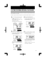
Confirming the Time Table Program settings
To confirm the programs that have been set, press the [SELECT] button and position the " "
over the "Time Table Program" mark. At that moment, the "Program No." flashes. And then
press the [CHANGE] button.
After you finish confirming the program, press the [SET] button 6 times.
Now the time table program setting has been completed. Replace the cover and lock.
Important: If you do not complete confirming the settings, the time recorder will not print.
Deleting the Time Table Program settings
Example: Deleting the "Program No. 2".
1 To
delete a program, make the
"Program No." flash, and press the
[CHANGE] button until the desired
program No. is displayed.
SU
BUZZ
MO
TU
WE
EXT.
*OFF
SIGNAL
SELECT
TH
FR
3 Press
the [SET] button. At that
moment, the display changes to the
following figure.
SA
TIME TABLE
PROGRAM
*ON
TIME TABLE
PROGRAM
CHANGE SET
Press the [SET] button. At that
moment, the display changes to the
following figure.
SELECT
SELECT
CHANGE
SET
2 Press the [CHANGE] button to set at
"
".
SET
4 After you finish deleting a program,
press the [SET] button once again.
SU
TIME TABLE
PROGRAM
CHANGE
MO
TU
WE
TH
FR
SA
Now the time table program setting
has been completed. Replace the cover
and lock.
Important: Printing will not occur
unless Step 4 is completed.
TIME TABLE
PROGRAM
38
SELECT
CHANGE
SET
36
40
19. SETTING THE EXTERNAL TIME SIGNAL / BUILT-IN BUZZER
With the optional board installed, the durations of External Time Signal and Built-in Buzzer
can be set from 1 to 30 seconds.
Example: Change the External Time Signal to 30 seconds and the Built-in Buzzer to 10 seconds.
1 Press the [SELECT] button and position
the " " over the "EXT. SIGNAL /
BUILT-IN BUZZ." mark.
At that moment, the flashing digit
indicates the "Ext. Signal".
(The flashing means it can be changed.)
Ext.
Signal
3 Change the "Built-in Buzzer".
In case of the example, press the
[CHANGE] button to set at "10". And
then press the [SET] button.
Built-in
Buzzer
EXT. SIGNAL
BUILT-IN BUZZ.
SELECT
CHANGE
SET
EXT. SIGNAL
BUILT-IN BUZZ.
SELECT
CHANGE
SET
2 Change the "Ext. Signal".
In case of the example, press the
[CHANGE] button to set at "30". And
then press the [SET] button.
4 After you finish setting the external
time signal / built-in buzzer, press the
[SET] button once again.
SU
EXT. SIGNAL
BUILT-IN BUZZ.
SELECT
CHANGE
SET
At that moment, the flashing changes
from the "Ext. Signal" to the "Built-in
Buzzer".
MO
TU
WE
TH
FR
SA
Now the external time signal / built-in
buzzer setting has been completed.
Replace the cover and lock.
Important: Printing will not occur
unless Step 4 is completed.
EXT. SIGNAL
BUILT-IN BUZZ.
SELECT
37
CHANGE
SET
39
41
20. SETTING THE SLAVE CLOCK
In this setup, you can select the Slave Clock.
Note: For this feature to be functional, the optional board must be installed in the Time
Recorder.
Clock Options
0.
Signal Options (for Slave Clock)
Disabled
Slave Clock
30.
30-second reversal
1.
60.
60-second reversal
2.
N/A
59.
59-minute impulse
Setting the Slave Clock
Example: Set the Slave Clock and 60-second reversal.
1 Press the [SELECT] button and position
the " "up the "SLAVE CLOCK" mark.
At that moment, the flashing digit
indicates "Clock Options".
(The flashing means it can be changed.)
2 Set the "Signal Options".
In case of the example, press the
[CHANGE] button to set at "60".
And then press the [SET] button.
Clock Options
SLAVE CLOCK
SELECT
CHANGE
SET
SLAVE CLOCK
SELECT
CHANGE
SET
Set the "Clock Options".
In case of the example, press the
[CHANGE] button to set at "1".
And then press the [SET] button.
At that moment, the flashing changes
from the "Clock Options" to "Signal
Options".
Signal Options
3 After
you finish setting the slave
clock, press the [SET] button once
again.
SU
MO
TU
WE
TH
FR
SA
Now the slave clock setting has been
completed. Replace the cover and
lock.
Important: Printing will not occur
unless Step 3 is completed.
SLAVE CLOCK
SELECT
40
CHANGE
SET
40
42
21. SETTING THE PASSWORD
When the password is set, you are asked to enter it. If the password you entered does not
coincide with the setting, you cannot change the setting values.
You may select any 4-digit number from 0001 to 9998 as your password.
Note : Numbers "0000" and "9999" are not valid passwords.
All settings must be reset if you forget the password. Refer to the "23. RESETTING".
Example: Set the password "1234".
1 Press the [SELECT] button and position
the " " over the "PASSWORD" mark.
At the moment, the first two digits flash.
(The flashing means it can be changed.)
PASSWORD
SELECT
2 Change the last two digits.
In case of the example, press the
[CHANGE] button to set at "34". And
then press the [SET] button.
PASSWORD
CHANGE
SET
Change the first two digits.
In case of the example, press the
[CHANGE] button to set at "12". And
then press the [SET] button.
SELECT
CHANGE
SET
3 After you finish registering the password,
press the [SET] button once again.
SU
MO
TU
WE
TH
FR
SA
PASSWORD
SELECT
CHANGE
SET
At that moment, the flashing changes
to the last two digits.
Now the password registering has
been completed. Replace the cover
and lock.
Important: Printing will not occur
unless Step 3 is completed.
41
41
43
How to change settings when the Password is set
Once the password is set, you are required to enter the current password before
changing any settings.
"9999" will be displayed when you press the [SELECT] button.
1 Press the [SELECT] button, at that
moment "9999" is displayed and the
first two digits flash.
(The flashing means it can be changed.)
SELECT
CHANGE
2 Set the last two digits.
In case of the example, press the
[CHANGE] button to set at "34". Then
press the [SET] button.
SET
Set the first two digits.
In the example, press the [CHANGE]
button to set at "12". And then press
the [SET] button.
SELECT
CHANGE
SET
SET
CHANGE
SET
TIME
SELECT
SELECT
CHANGE
At that moment, the " " mark indicates
the "TIME".
At that moment, the flashing changes
to the last two digits.
3 Select
desired setting mode by
pressing the [SELECT] button.
Then make any changes to settings as
explained.
42
42
44
Canceling the Password
The code "0000" must be entered to cancel the password.
Example: Cancel the password "1234".
1 Press the [SELECT] button, at that
3 Press the [SELECT] button and position the
moment "9999" is displayed and the
first two digits flash.
(The flashing means it can be changed.)
" " over the "PASSWORD" mark. At that
moment, the first two digits "12" flash.
(The flashing means it can be changed.)
SELECT
CHANGE
SET
In the example, press the [CHANGE]
button to set at "12". And then press
the [SET] button.
SELECT
CHANGE
SET
At that moment, the flashing changes
to the last two digits.
PASSWORD
SELECT
CHANGE
SET
Press the [CHANGE] button to set at
"00". And then press the [SET] button.
PASSWORD
SELECT
CHANGE
SET
At that moment, the flashing changes
to the last two digits "34".
4 Press the [CHANGE] button to at set "00".
2 In
case of the example, press the
[CHANGE] button to set at "34". And
then press the [SET] button.
And then press the [SET] button.
PASSWORD
SELECT
SELECT
CHANGE
CHANGE
SET
SET
5 After you finish canceling the password,
press the [SET] button once again.
SU
TIME
SELECT
CHANGE
SET
At that moment, the " " mark indicates
the "TIME".
43
MO
TU
WE
TH
FR
SA
Now the password canceling has been
completed. Replace the cover and lock.
Important: Printing will not occur
unless Step 5 is completed.
43
45
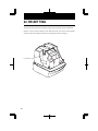
22. RE-SETTING
To return all setting to the factory defaults, push the reset switch with a pointed implement.
NOTICE: All your custom settings will be deleted and will revert to the factory defaults
when the reset switch is pushed. To make new settings, please refer to "Setting ···".
Reset Switch
44
44
46
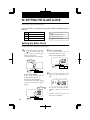
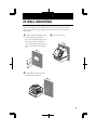
23. WALL MOUNTING
Caution: The supplied screws are intended for use on a thick wooden wall or wooden
column. Do not use any other materials. The time clock may come off if used on
other materials.
1 Install the supplied wall-mount screws
3 Replace cover and lock.
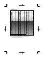
into a wall by using the template.
Be sure to keep about 6mm (1/4") of
the screw head away from the wall.
The recommended height from the
floor to the bottom of the ES900 is
45".
WA
LL
WA
LL
2 Unlock the key and remove the cover.
And then hang it on the wall.
WA
LL
45
45
47
24. REPLACING THE RIBBON CASSETTE
1 Unlock the key and remove the cover.
3 Turn the knob of the new cassette in
the direction of the arrow (clockwise)
to tighten the ribbon.
2 Hold the ribbon cassette by its tab and
pull straight out to remove it.
46
4 Place
the cassette inside the time
recorder as shown in the figure. Push
the ribbon until it snaps into position.
Turning the knob on the ribbon
cassette may make installation easier.
46
48
Print head
Ribbon mask
Ribbon
NOTE: Install the cassette so that the
ribbon is between the print head and the
ribbon mask. Printing will not come out
properly if the ribbon is placed behind
the ribbon mask.
5 Turn the knob of the cassette in the
6 Replace the cover and lock.
direction of the arrow to tighten the
ribbon.
47
47
49
25. CHARACTER CODE FOR ALPHANUMERIC
Num: Sequential number HH: Hour MM: Minute
1
15: Language-Specific Character
Code
NULL
Max.
Dots
–
SPACE
3
Character
Code
SS: Second
Meaning
DOW: Day of the week
Code
Meaning
Insert Character
Exchange Line 1 to 2
Delete Character
Exchange Line 2 to 3
Insert Line
Exchange Line 3 to 1
Delete Line
Delete All
Large (BOLD) Character
Code
48
A
Max.
Dots
8
Z
Max.
Dots
8
4
Max.
Dots
-
B
8
0
8
5
-
C
8
1
8
6
-
D
8
2
8
7
-
E
8
3
8
8
-
F
8
4
8
9
-
G
8
5
8
10
-
H
8
6
8
11
-
Character
Code
Character
Code
Character
I
5
7
8
12
-
J
8
8
8
13
-
K
8
9
8
14
-
L
8
Year
32(19)
15
-
M
8
Month
24
´
3
N
8
Date
16
O
8
DOW
16
+
7
P
8
HH:MM
37(49)
,
5
Q
8
HH:MM:SS 58(70)
-
7
R
8
Number
8x(n)
.
5
S
8
Number
8x(n)
/
8
T
7
Number
8x(n)
:
5
U
8
Number
8x(n)
;
5
V
8
Number
8x(n)
_
6
W
8
1
-
&
10
X
8
2
-
Y
7
3
-
7
Note: ( ) is to indicate the following meanings.
Code=26: 2 digits setting of YEAR, Code=2A and 2b:AM/PM setting of HOUR,
Code=2C to 30: Number digits depend on the setting.
48
50
Large Character
Code
A
Max.
Dots
7
Z
Max.
Dots
7
4
Max.
Dots
-
B
7
0
7
5
-
C
7
1
7
6
-
D
7
2
7
7
-
E
7
3
7
8
-
Character
Code
Character
Code
Character
F
7
4
7
9
-
G
7
5
7
10
-
H
7
6
7
11
-
I
4
7
7
12
-
J
7
8
7
13
-
K
7
9
7
14
-
L
7
Year
28(18)
15
-
M
8
Month
22
´
3
N
7
Date
14
O
7
DOW
15
6
+
6
P
7
HH:MM
32(44)
,
4
Q
7
HH:MM:SS
50(62)
-
6
R
7
Number
7x(n)
.
4
S
7
Number
7x(n)
/
6
T
6
Number
7x(n)
:
4
U
7
Number
7x(n)
;
4
Number
V
7
7x(n)
_
5
W
8
1
-
&
9
X
7
2
-
Y
6
3
-
Note: ( ) is to indicate the following meanings.
Code=6F: 2 digits setting of YEAR, Code=73 and 74:AM/PM setting of HOUR,
Code=75 to79: Number digits depend on the setting.
49
49
51
Small Character
Code
A
Max.
Dots
6
7
Max.
Dots
6
HH:MM
Max.
Dots
26(37)
B
6
8
6
HH:MM:SS
40(57)
C
6
9
6
Number
6x(n)
D
6
a
5
Number
6x(n)
E
6
b
5
Number
6x(n)
F
6
c
5
Number
6x(n)
G
6
d
5
Number
6x(n)
H
6
e
5
1
-
I
4
f
4
2
-
Character
Code
Character
Code
Character
J
6
g
5
3
-
K
6
h
5
4
-
L
6
i
2
5
-
M
6
j
3
6
-
N
6
k
5
7
-
O
6
l
2
8
-
P
6
m
6
9
-
Q
6
n
5
10
-
R
6
o
5
11
-
S
6
p
5
12
-
T
6
q
5
13
-
U
6
r
5
14
-
V
6
s
5
15
-
W
6
t
4
´
3
X
6
u
5
Y
6
v
5
+
6
Z
6
w
6
,
4
0
6
x
6
-
5
1
6
y
5
.
4
2
6
z
6
/
6
3
6
Year
24(15)
:
4
4
6
Month
18
;
4
5
6
Date
12
_
4
6
6
DOW
12
&
8
6
Note: ( ) is to indicate the following meanings.
Code=d2: 2 digits setting of YEAR, Code=d6 and D7:AM/PM setting of HOUR,
Code=d8 to dc: Number digits depend on the setting.
50
50
52
Language-Specific Character
English
Character
#
$
@
[
\
]
^
`
{
|
}
~
EURO
Dots Bold
9
9
9
7
8
7
8
5
7
5
7
7
8
Large
7
6
7
6
6
6
6
4
6
4
6
6
7
Small
6
6
6
5
6
5
4
3
5
4
5
6
6
Character
Pt
$
@
¡
Ñ
¿
´
`
¨
ñ
}
~ EURO
Dots Bold
11
9
9
5
8
7
5
5
9
7
7
7
8
Large
8
6
7
4
7
6
4
4
7
7
6
6
7
Small
8
6
6
4
6
6
3
3
7
6
5
6
6
Character
#
$
§
Ä
Ö
Ü
^
`
ä
ö
ü
ß EURO
Dots Bold
9
9
8
8
8
8
8
5
7
7
7
8
8
Large
7
6
7
7
7
7
6
4
7
6
6
7
7
Small
6
6
6
6
6
6
4
3
5
5
5
6
6
Character
#
$
à
˚
ç
§
^
`
é
ù
è
¨
EURO
É
Dots Bold
9
9
7
4
7
8
8
5
7
7
7
9
8
8
Large
7
6
7
4
6
7
6
4
6
6
6
7
7
7
Small
6
6
5
4
5
6
4
3
5
5
5
7
6
6
Character
#
$
@
Dots Bold
9
9
9
Large
7
6
7
Small
6
6
6
˚
4
4
4
Character
#
$
@
[
\
]
^
`
{
Dots Bold
9
9
9
7
8
7
8
5
7
Large
7
6
7
6
6
6
6
4
6
Small
6
6
6
5
6
5
4
3
5
Character
#
$
@
[
\
]
^
`
{
Dots Bold
9
9
9
7
8
7
8
5
7
Large
7
6
7
6
6
6
6
4
6
Small
6
6
6
5
6
5
4
3
5
Spanish
German
French
Italian
\
é
^
ù
à
ò
è
ì
EURO
8
7
8
7
7
7
7
5
8
6
6
6
6
7
6
6
4
7
6
5
4
5
5
5
5
4
6
|
}
~
EURO
5
7
7
8
4
6
6
7
4
5
6
6
|
}
~
EURO
5
7
7
8
4
6
6
7
4
5
6
6
Portuguese
Numeric
51
51
53
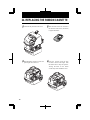
26. INSTALLING THE OPTIONAL Ni-Cd BATTERY
This option allows for printing up to 200 registrations without AC power.
Order Acroprint Part Number 58-0108-000, optional battery pack, for this feature.
1 Unlock the key and remove the cover.
3 Replace the cover and lock.
2 Insert the battery connector into the
compartment connector to install the
battery.
52
52
54
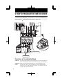
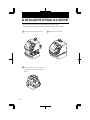
27. CONNECTING THE OPTIONAL FUNCTIONS
Connecting the Master Clock
CAUTION: Be sure to pull out AC cord from AC outlet before connecting wires of the
Master Clock.
Improper connection may cause a malfunction of the unit.
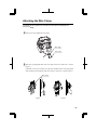
Also refer to "Attaching the Wire Clamp" to secure wires with the wire
clamp.
1 Unlock the key and remove the cover.
3 Insert wires into two left terminals for
the master clock, and tighten both
screws.
Insert the " + " 30/60 second
signal cable. reversal
Insert the "AB" 59 minute
impulse
signal cable.
(2-wire)
Insert the " - "
signal cable. 30/60 second reversal
Insert the " PC " 59 minute impulse
(2-wire)
signal cable.
2 The connector for the master clock
signals is on the back of
recorder.
4 Replace the cover and lock.
the time
connector
M
C AS
UN LOC TER
IT K
OPT
ION
53
AL
53
55
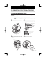
Connecting the External Time Signal
If external signal(s) are required, the addition of a relay (not supplied) will be necessary.
Please consult your local electrician.
When a signal is activated the internal contacts close completing the circuit. These internal
contacts are "dry" and supply no voltage. Voltage applied to these contacts must not exceed
30 volts. An external relay must be used to activate signaling devices.
Recommended Relays: (Or similar line voltage switching relays)
Available at W. W. Grainger
HoneyWell
#RA89A1074
Grainger #2E866
Dayton
#809A-189
Grainger #2E553
120 VAC
Nuetral
2
ES900
Internal
Relay
1
External
Relay
3
4
External
Signal
30V
Class 2
Connections shown for Dayton 2E553. Add jumper from terminals 1 to 3.
CAUTION: Be sure to pull out AC cord from AC outlet before connecting wires of the
External Time Signal. Improper connection may cause a malfunction of the unit.
Also refer to "Attaching the Wire Clamp" to secure wires with the wire clamp.
1 Unlock the key and remove the cover.
2 Insert wires into two right terminals
for external time signal, and tighten
both screws.
54
54
56
Attaching the Wire Clamp
CAUTION: Be sure to pull out AC cord from AC outlet before attaching the wire
clamp.
1 Remove two screws holding the wire clamp.
Wire clamp
Two screws
2 Make wires go through the hole of the wire clamp and secure it with screws.
(See the
Figure 1.)
If diameter of wires is too small to fix by the above method, turn the wire clamp upside
down and feed wires through the clamp. Then secure it with screws. (See the Figure 2.)
Wire clamp
Figure1
57
Figure 2
55
57
28. TROUBLE-SHOOTING
Error No. appears
Refer to the following list for proper operation.
No.
Error contents
E-00
CPU error
E-01
The remaining life of lithium battery for
memory back-up is short.
E-05
The card is not inserted in the Time Stamp
properly.
E-30
Cannot print.
The printer motor or home position sensor is not
normal.
Action
Contact Acroprint at (800) 334-7190 (in USA).
Correctly insert the card.
Make sure that the ribbon cassette is correctly
inserted in place.
Press the push bar.
E-38
Cannot print.
The printer head motor or the sensor does not
operate properly.
E-40
Incorrect password
Enter the correct password again.
E-41
D.S.T. setting mistake
Confirm the correct starting and ending dates of
daylight saving time and enter again.
E-49
Setting data you entered is not usable.
Refer to your user's manual on the page related to
the item you want to set and enter correct setting
data.
OTHER FAILURES
•The time recorder does not operate.
Ensure the power cord is properly plugged into the AC outlet and power is available.
•The time recorder does not print.
Ensure the ribbon is installed correctly and the proper print method is set.
•The card is jammed.
Press the push bar and try to pull out the card at the same time.
•Fails to hold memory.
Replace lithium battery with Toshiba, part number ER3VT2.
56
56
58
29. SPECIFICATIONS
Clock accuracy
Monthly accuracy ± 15sec. (at ordinary temperatures)
Calendar
Year up to 2099. Automatically adjusted to leap years, 31-day
months and months with thirty or fewer days, and the days of the
week.
Printing system
Dot matrix
Power failure
compensation
Three years of cumulative power failure hours after the date of
shipment.
Print at power
failure
Optional Ni-Cd battery, 200 print registrations or 24 hours
Acroprint part number 58-0108-000
Lithium battery
Toshiba part number ER3VT2
Time program
External time signal
Built-in buzzer
Printing an I Mark (*)
Connection of
external signal
Operating
environment
57
Connection with optional functions.
External Alarm device : No voltage signal output.
Master Clock device : 6 to 32 V signal input.
Temperature: -5˚ to +45˚C, +25˚ to +113˚F
Humidity: 20 to 80%, no condensation
The unit operates normally at temperatures of 5˚C or below, but
the print density, reaction of the liquid crystal display, and
the number of prints at power failure are inferior to those at
normal temperature operation.
Dimensions
6.14" (w) x 7.13" (h) x 6.97" (d)
156 (w) x 181 (h) x 177 (d) mm
Weight
Approx. 4.0 lbs. (1.8kg)
Rating
120VAC 50/60Hz 0.4A
220-240VAC 50/60Hz 0.2A
57
59
5640 Departure Drive
Raleigh, North Carolina 27616 USA
(919) 872-5800
In USA (800) 334-7190
Fax: (919) 850-0720
www.acroprint.com
P/N 06-0316-000 Rev. A
60