1
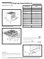
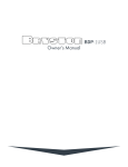
CR1001SS Range Cooker
INSTRUCTIONS - &
Recommendations for use, installation
& maintenance of this appliance
Dir. 89/336 CEE
73/23 CEE
Quality Products
Consumer Help Line 0870 241 1142
THIS MANUAL CONTAINS:
•
•
•
•
User’s instructions
Cooking guide
Installation instructions
Servicing instructions
Appliance conformity
– The appliance complies with European Directives EEC 89/336,
92/31 and 93/68 relative to electromagnetic compatibility.
– All our appliances are designed and constructed in compliance
with European standards EN 60 335-1 and EN 60 335-2-6
and their subsequent amendments, in conformance with the
requirements of the European Low Voltage Directive EEC
73/23 and 93/68.
– The oven accessories that can come into contact with food are
constructed using materials that conform to European
directive EEC 89/109 of 21/12/88.
– The appliances are constructed in compliance with European
gas directives EEC 90/396, EEC 93/68 and European
standards EN 30-1/EN 30-2.
– The conformity to the standards is proved by symbol CE
applied.
This booklet is valid only for the country of installation
indicated on the back cover and on the appliance itself.
Carefully keep this booklet for future reference.
TO THE OWNER OF THE COOKER
Retain this owner’s manual for future reference.
TO THE INSTALLER:
Leave this owner’s manual with the cooker.
The cooker model and its technical data (power, supply voltage,
etc.) appear on the data plate affixed to the inner side of the
Plate Warming Door. The factory settings are indicated on the
label affixed beside the data plate.
Caution: When in use parts of the cooker become very hot (e.g.
the burners) and remain hot for a long period of time. Use of
oven gloves is recommended whilst using your cooker. Children
should be kept away from the appliance.
– Make sure there is adequate air circulation around the cooker.
Poor ventilation reduces the amount of oxygen in the room. If in
doubt, consult the installer. In the interest of hygiene and
safety, the cooker should always be kept clean.
– Deposits of grease or other foods can catch fire. Carefully
supervise the cooking of oils or fat.
– When you first use your cooker it may give off a slight odour
but this will stop after a little use.
– This product has been designed for domestic cooking only and
should not be used for other purposes (such as heating a
room).
– Avoid installing the cooker close to flammable materials (e.g.
curtains, drapes, etc...)
– Operate the cooker with the type of gas specified on the
adhesive label placed in the inner side of the Plate Warming
Door.
– Before cleaning or servicing the appliance, disconnect it from
the electricity supply by unplugging it or by using the main
circuit breaker.
Please note: The connection hose and the chain are part of the
installation not part of the cooker. They should be provided by
your installer and are available at most builders merchants.
“THIS COOKER GUARANTEE IS FOR DOMESTIC
USE ONLY”
This booklet gives valuable instructions covering the installation,
servicing and use of your cooker.
Important
After using the cooker, it is advisable to:
– Always check that the control knobs are in the “ ” position.
– Also close the gas cylinder valve (if LPG is used) or the supply
cock (if natural gas is used).
– Periodically inspect the rubber hose. If it shows any signs of
wear it must be replaced: never repair the gas hose.
Contact your qualified installer.
FOR YOUR SAFETY
The installation must be performed by a competent installer,
properly qualified as required by local regulations. Any rewiring
required of the household electrics in order to install the
cooker should only be carried out by a Qualified Electrician. The
manufacturer declines all responsibility for any type of
damage resulting from failure to observe the regulations, or
from negligent installation of the cooker.
For repairs, always call in an authorised Technical Service Centre
and insist on the use of original spare parts.
3
Contents
CHARACTERISTICS ........................................................................................................................................................................................
P. 5
INSTRUCTION FOR USE ...............................................................................................................................................................................
P. 6
TIMER FUNCTION .............................................................................................................................................................................................
P. 11
COOKING GUIDE ...............................................................................................................................................................................................
P. 13
COOKER CLEANING ........................................................................................................................................................................................
P. 13
COOKER SERVICING.......................................................................................................................................................................................
P. 14
TECHNICAL NOTICE FOR INSTALLER.....................................................................................................................................................
P. 17
BEFORE CALLING FOR ASSISTANCE....................................................................................................................................................
P. 21
ADDITIONAL NOTES FOR ASSEMBLING THE SAFETY CHAIN.................................................................................................
P. 22
4
Characteristics
DIMENSIONS OF THE COOKERS
COOKER DIMENSIONS
AND CHARACTERISTICS
TWIN
100X60
Height of top
a1=
90±1 cm
Depth
C1=
60 cm
Width
B=
100 cm
Height to top
of splashback
a2=
96±1 cm
Depth with
over door open
C2=
94 cm
Working capacity litres
left 57
right 33,5
Class
Combined and electric
cooker type
Ec type examination
certificate n.
Ec type
examination
fig. 1
DESCRIPTION: CONTROL PANEL
Y
49 BL 3157
49 BL 3155
2017
1017
Burners are adaptable for Bufane - Propane - Natural Gas Category II 2H3+
Operating voltage
230 - 240 V 50Hz
fig. 2
1) Digital programmer or analogue clock or timer knob
2) Position of control knobs and their corresponding burners
3) Control knobs for the gas burners
of the electric hot plates
4) Thermostat knob, electric oven/grill control knob
5) Warning lights
DATA PLATE
Before connecting the electricity and gas supplies, carefully read
the technical data plate affixed to the inner side of the Plate Warming Door (fig. 3). This will indicate the series, number and model
of the cooker.
fig. 3
5
Instructions for use
Twin model ovens and grills
The standard conformation consists of a multifunction oven on
the left and a static oven on the right.
The left oven is equipped with grill with an energy regulator.
The right oven is equipped with a fixed grill (with turnspit).
Runners
The shelves slot into the runners “A” .These runners (see Fig. 6)
mean that dishes can be cooked at different heights, 10 for twin
model, selecting the best height for the particular dish.To remove
the shelves see fig. 6.To remove the shelves from the oven, pull and
lift as shown in Fig. 6/A below.
fig. 4
fig. 5
USING THE BURNERS
fig. 6
Automatic electric ignition of burners
To light the burner of the hob selected for cooking, push in the corresponding knob and turn in an anti-clockwise direction to the fully on position (shown in Fig. 4); when pressed fully in, the spark will
be generated automatically, igniting the burner.
IMPORTANT: Do not operate the spark ignition button for a long
time, as this can damage the spark generator.
To shut off the gas supply, turn the knob in a clockwise direction
to the position (gas supply off).
Suggestions for conserving energy
Avoid using pans that are too small for the burner, so that the flames don’t lick up the sides of the pan. When the contents have
boiled, reduce the flame setting to a simmer by turning the knob
anticlockwise (fig. 4). To facilitate saving gas, the hob has burners
with different diameters and power ratings. Use the appropriate
burner for each type of pan, as detailed below:
Rapid burner
R
Pan diameter from cm 24/26
Semi-rapid burner
B
Pan diameter from cm 16/18
Auxiliary burner
A
Pan diameter from cm 12/14
BK
Pan diameter from cm 24/26
Kwali triple flame burner
6
fig. 6/A
Tips
Open and close the oven door gently and never leave it ajar when
the oven is hot. This could cause damage to the control knobs.
Cooling fan
Your cooker is fitted with a fan to cool the control panel, the
oven doors and the oven door handles.It switches on automatically when the temperature reaches a certain level. The
green light on the control panel shows that the fan is operating. The fan stops automatically at the end of cooking when
the temperature of the appliance has dropped to a sufficiently safe level.
MULTIFUNCTION OVEN
- Allows different types of food to be cooked on more than one
shelf.
- Also allows natural convection cooking.
- 8 different cooking functions can be activated.
- Controlled by two or three knobs:
- When knob (1) (Fig. 9) is turned a selector activates the cooking
functions identified by the symbols:
- Twin oven cookers have 5 indicator lights:
- Green light: indicates operation of a fan under the hob to cool
the oven doors, front panel and exposed parts.
- Red lights: there are two. The left-hand light indicates that an
electric element in the left oven is on, and the right-hand light
operation of an electric element in the right oven.
- Yellow lights: there are two. The left-hand light indicates that
the left oven or grill is in operation, the right-hand light operation
of the right oven or grill.
The lights go out when the corresponding oven reaches the set
temperature.
During cooking the light will continue to switch on and off, reflecting the controlling action of the thermostat.
-
Oven off.
-
Oven light on (it remains on in all functions).
-1
top and bottom elements on (static cooking).
-2
grill element on (grilling).
-3
fan on without heat (food thawing).
-4
fan and back element on (fan oven).
-5
fan and grill element on (fan grilling).
-6
fan, back element and top element on (delicate cooking
at constant temperature).
-7
fan and top and bottom elements on (fan assisted
cooking).
-8
fan and back and grill elements on (rapid grilling).
STATIC ELECTRIC OVEN (right oven)
The electric oven is heated by a bottom element under the oven
bottom plate, a top element on the top of the oven and a third element in the top of the oven in the grill position. The thermostat
switches the elements on and off to maintain the set temperature in the oven.
- As the oven knob marked with the
symbol is turnedclockwise, it encounters the following symbols (Fig. 7).
-
Oven off.
-
Oven light on (it remains on in all functions).
-
60-110-160-220-240-max (oven temperature).
-
Bottom element on.
-
Top element on.
-
Grill element on, turnspit on.
Knob (2) controls the temperature setting.
Knob (3) controls the energy regulation of the grill.
The red light indicates that one of the electrical components is
on.
The yellow light indicates that the thermostat is on.
When using the grill, keep the oven door closed.
Hints for cooking in a multifunction oven.
(Page 11 cooking guide).
The multifunction oven works when the clock/programmer is set in
“manual” or in any programming position.
The red light indicates that one of the electrical components
is on.
The yellow light indicates that the thermostat is on.
fig. 9
fig. 7
Using the electric grill
The same knob that controls the electric oven (Fig. 7) also switches on the grill element, when turned all the way to the right. The
grill position is marked with the symbol
.
7
Setting 1 - conventional cooking (static oven)
(fig. 10 - 10/A)
- Turn knob (1) symbol
.
- Knob (3) (grill energy regulator) to zero
- The heating elements are in operation.
- The red light confirms they are in operation.
- Turn the thermostat knob (2) to the chosen temperature.
- The yellow light comes on.
- Wait for the yellow light to go out before placing the foods in the
oven.
- This cooking mode is suitable for biscuits, cakes, bread and roasts.
fig. 11
fig. 10
fig. 11/A
Setting 3 - thawing frozen foods
(forced ventilation) (fig. 12 - 12/A)
fig. 10/A
- Turn knob (1) to symbol
- Knob (3) to zero
- Only the fan is switched on to circulate air at room temperature.
- The red light indicates it is in operation.
- Turn the thermostat knob (2) to zero.
- This function is suitable for thawing frozen foods.
- Thawing times depend on the quantity of food to be thawed.
Setting 2 - grilling (fig. 11-11/A)
- Turn knob (1) to symbol
- Turn knob (3) to 6.
- The grill element is in operation.
- The red light confirms it is in operation.
- Turn the thermostat knob (2) to max.
- The yellow light comes on.
- This cooking mode is suitable for grilling meat, fish and vegetables. It can also be used for grilling bread and bacon. Arrange the
foods on the grill grid and place it on the chosen runners.
- The oven door must be kept closed during grilling.
- Turning the knob N°3, you can select a gradual variation of the
grill cooking temperature (main oven only).
Note: When using the grill keep the oven door closed.
8
fig. 12
Setting 5 - fan grilling (gentle grilling) (fig. 14 - 14/A)
- Turn knob (1) to symbol
- Turn knob (3) to 6.
- The grill element and the fan on the back of the oven are ope-rating.
- The red light confirms they are in operation.
- Turn the thermostat knob (2) to the chosen temperature.
- The yellow light comes on and will go out when the chosen temperature is reached.
- Arrange the foods on the grill grid and place it so that the foods
are about 5 cm below the element.
- Place the tray on the appropriate runners.
- To prevent smoking, pour a little water into the tray and keep the
level topped up during cooking.
- The oven door must be kept closed.
- This cooking mode is an alternative to the turnspit; the fan comes on and distributes the heat radiated by the grill.
- It is especially suitable for meat, roasts and poultry.
- Turning the knob N° 3, you can select a gradual variation of the
grill cooking temperature.
fig. 12/A
Setting 4 - hot air cooking (fan oven)
(fig. 13 - 13/A)
- Turn knob (1) to symbol
- Knob (3) to zero
- The fan and the circular element on the back of the oven are
switched on.
- The red light indicates they are in operation.
- Turn the thermostat knob (2) to the chosen temperature.
- The yellow light comes on and will switch off when the set temperature is reached.
- Wait for the yellow light to go out before placing the foods in the
oven.
- The heat is spread evenly through the inside of the oven.
- Different types of food can be cooked on more than one shelf.
- This cooking mode is especially suitable for cakes, meat and fish.
- When more than one shelf is used, the cooking times indicated
must be increased by approximately 10/15 min.
fig. 14
fig. 14/A
fig. 13
Setting 6 - delicate cooking
(constant temperature) (fig. 15 - 15/A)
fig. 13/A
- Turn knob (1) to symbol
- Turn knob (3) to Zero.
- The top electric element, the back element and the fan on the
back of the oven are operating.
- The red light confirms they are in operation.
- Turn the thermostat knob (2) to the chosen temperature.
9
- The yellow light comes on and will go out when the chosen temperature is reached.
- This cooking mode is suitable for cakes in general and for warming serving dishes.
- Wait for the yellow light to go out before placing the foods in the
oven.
- This cooking mode is especially suitable for cooking large
amounts of food, such as roasts, turkey, etc.
fig. 16/A
fig. 15
Setting 8 - rapid grilling (fig. 17 - 17/A)
- Turn knob (1) to symbol
- Turn knob (3) to 6.
- The top electric element, the grill, the circular element at the
back of the oven and the fan are operating.
- The red light confirms they are in operation.
- Turn the thermostat knob (2) to the chosen temperature.
- The yellow light comes on and will go out when the chosen temperature is reached.
- Wait for the yellow light to go out before placing the foods in the
oven.
- This function is an alternative to the turnspit for cooking large
amounts of food such as lamb, turkey, chops, sausages, etc.
- Turning the knob N° 3, you can select a gradual variation of the
grill cooking temperature.
fig. 15/A
Setting 7- conventional fan cooking
(fan assisted oven) (fig. 16 - 16/A)
- Turn knob (1) to symbol
- Turn knob (3) to Zero.
- The top and bottom electric elements and the fan on the back of
the oven are operating.
- The red light confirms they are in operation.
- Turn the thermostat knob (2) to the chosen temperature.
- The yellow light comes on and will go out when the chosen temperature is reached.
fig. 17
fig. 17/A
fig. 16
10
Timer function
Electronic cooker programmer
COOKING DURATION button and adjust how long you wish the
oven to cook with the +/- buttons. Then set the time you wish
cooking to END by pressing the END TIME button and adjusting
the time with the +/- buttons. Turn the Temperature and Function
knobs to the desired positions. The symbol “A” will appear on the
screen. When the oven turns an a cooking pot symbol will also appear on the screen. When cooking is finished the oven will turn off,
the cooking pot symbol will disappear and an allarm will sound.
fig. 18
AUTOMATIC
PROGRAM
E
E
SE
E
C
EA
U
R
ED
C
R
+
IN
—
MINUTE MINDER
This works as a simple alarm. Press the MINUTE MINDER button
and adjust the number of minutes with the +/- buttons.
When the set time has elapsed the alarm sounds.
TI
TI
M
M
G
N
KI
O
O
C
D
EN
KI
O
O
C
M
IN
N
U
G
TE
D
U
-M
R
IN
AT
I
D
O
ER
N
A
FUNCTIONS
Cooking duration, cooking end time, time of day, minute minder “-”,
“+”, manual selection.
DISPLAYS
4-digit, 7-segment display for time of day and switching times.
“Dialogue” display to identity condition of timer:
Duration and manual mode = Cookpot symbol
Automatic programme
=A
Minute minder
= Bellsymbol
AUDIBLE SIGNAL
The alarm will sound for a maximum of 7 minutes.
To turn the sound off press any function button.
You can choose from three different sounds by pressing the –
button on its own.
PROGRAMME START AND VERIFICATION
Once a programme has been started you can check how long it has
to run by pressing the appropriate function button.
SETTING ERROR IDENTIFICATION
The setting is incorrect if time of day is in between the calculated
cooking start and end times. If an error has been made, this will be
indicated by the alarm and by the symbol “A” flashing.
CANCELLING A PROGRAMME
A programme can be cancelled by setting the oven to Manual
(press the COOKING DURATION and END TIME buttons together).
SETTING
Select a function by pressing the function button and set the required time with the +/- buttons.
+/- BUTTONS
Pressing the “+” button increases the time set, pressing “-” decreases it. The count-up or count-down speed increases the longer the button is held in the appropriate position.
SETTING TIME OF DAY
Set time of day by pressing the COOKING DURATION and END TIME buttons together and adjust with +/- buttons.
MANUAL COOKING
To clear any programmes and use the oven normally press the
COOKING DURATION and END TIME buttons together.
SEMI-AUTOMATIC COOKING
To set the oven to stop cooking automatically press the COOKING
DURATION or the END TIME button and use +/- buttons to set
how long you wish cooking to continue. Turn the appropriate temperature and function control knobs to the desired positions.
Cooking will start immediately. When the set time has elapsed the
oven will stop cooking, the alarm will sound and the symbol “A” will
blink.
Press any button to turn the alarm off. Turn the dials to the Off
positions.
FULLY AUTOMATIC cooking
To set the oven to turn on and off at a future time first press the
11
Griddle plate (not supplied - optional extra)
Panset use
Before using for the first time: wipe the surface of the griddle plate with oil and heat so that the oil evaporates (repeat after each
use). Place the griddle plate on the central burner. Pre-heat for 5
minutes. The control knob can be turned to a lower position.
Using a pan set in a right-hand oven
For cooking operations requiring the use of the oven shelf, the tray
provided should be placed in the runners beneath the shelf, as
shown in fig. 20, in order to collect the drops of fat.
Caution: the Griddle wil be very hot when used. If handling ensure adeguate protection is used.
Young children should be kept away from the appliance.
Plate Warming compartment
To access the compartment, open the door as shown in fig. 19,
pressing the centre of the door. Do not store dusters or other
flammable objects in the compartment.
The plate warming compartments are useful storage areas. They
get warm during use of the ovens and can be used to warm your
plates or dishes.
fig. 20
To grill using the PAN SET, the tray can be placed on the shelf with
the TRIVET inside the tray (fig. 20/A). Place the shelf on the runners most suitable for the cooking procedure, bearing in mind that
the food should be about 5 centimetres (two inches) from the grill
element.
fig. 19
When using the turnspit, it is best to place the shelf on the bottom runners and place the tray on the shelf to collect the drops
of fat (fig. 20/B).
fig. 20/A
fig. 20/B
12
Cooking guide
OVEN COOKING CHART
The oven control setting and cooking times given below are intended to be used only as a guide. Individual taste may require the
temperature to be altered to provide a preferred result.
For best results preheat the oven until the yellow light goes out.
fig. 21
LEFT OVEN
SINGLE CAVITY
RIGHT OVEN
TEMPERATURES
°C
POSITION
ON
RUNNERS
COOKING
TIME
MINUTES
TEMPERATURES
°C
POSITION
ON
RUNNERS
COOKING
TIME
MINUTES
TEMPERATURES
°C
POSITION
ON
RUNNERS
COOKING
TIME
MINUTES
SPONGE CAKES
200
/
40 - 50
180
4°
35
200
/
40 - 50
VICTORIA SANDWICH
200
2° - 7°
25
/
/
/
200
2° - 7°
25
BISCUITS
200
2° - 7°
15
180
2°
15
200
2° - 7°
15
SCONES
240
2° - 7°
15
220
2°
15
240
2° - 7°
15
SMALL CAKES
180
2° - 7°
20 - 25
160
2°
30
180
2° - 7°
20 - 25
MERINGUES
110
2° - 7°
120
85
2°
120
110
2° - 7°
120
Note: Guide Only
200
4° - 6°
20 per Kg + 20
180
4° - 6°
25 per Kg + 25
200
4° - 6°
20 per Kg + 20
GRILL
7° - 9°
7+7
GRILL
7° - 9°
5+5
GRILL
7° - 9°
7+7
LAMB
200
4° - 6°
35 per Kg + 35
180
4° - 6°
35 per Kg + 35
200
4° - 6°
35 per Kg + 35
PORK
200
4° - 6°
35 per Kg + 35
180
4° - 6°
35 per Kg + 35
200
4° - 6°
35 per Kg + 35
SOUFFLÉ
200
2° - 3°
35 - 40
200
2° - 3°
35 - 40
200
2° - 3°
35 - 40
BEEF
T-BONE STEAK (GRILLED)
PIZZA
240
4° - 6°
40
240
4° - 6°
40
240
4° - 6°
40
GRATIN DAUPHINOIS
180
4° - 6°
50 - 70
160
4° - 6°
50 -70
180
4° - 6°
50 - 70
Cooker cleaning
Never use detergent, abrasive powder and strong cleaning products
that might damage the surfaces. Never use metal pads, steel wool,
scourers, knives or similar tools which scatch surfaces.
Hot
Soapy
Water
Hob
MoinNylon
stened Aerosols*
Scourer Soap
Pad
Pan support
Enamelled, stainless steel and painted surfaces
Wash using a soft moistened soap pad (with neutral soap). Wipe and
rinse with cold water. Dry using chamois leather or similar product.
Burner caps
Enamelled burner caps and pan supports
Allow the burners and pan supports to cool before cleaning.
Wash with a sponge and soap. If the openings are blocked, do not use
metallic objects to clear them; preferably use a wooden tooth-pick.
Griddle Plate
Flame divider
Hob
Dish warmer door
Oven cavities Inside Oven**
Oven glass
Glass windows
To clean the window in the oven door, use a sponge covered with a
small amount of soapy detergent. Rinse with cold water. Repeat for
the internal glass.
Door stripes
Cleaning of self-cleaning catalytic oven
Heat the oven to Max for about 1 hour. Allow to cool and gently wash
with a soft moistened pad. Reheated for quarter of an hour maximum temperature for the oven to dry out.
Runners
Griddle plate (optional extra)
Clean the griddle only when cold using a damp sponge and soap. If
food remnants are difficult to remove, leave the plate to soak in water, then wash with a sponge. Never use metallic objects such as knives, forks, brushes, etc.
WARNING: Avoid pouring water directly on to the plate when it is hot.
Dishwasher
Safe
Door seal
Drip tray
Baking tray
Grill set
Grill grid
Other
Side Panels
Knobs
Handle
* Aerosols recommended for use on vitreous enamel
** For self-cleaning ovens refer to page 13.
13
Cooker Servicing
GENERAL RULES
All servicing operations described in this section must be carried
out by qualified personnel only.
Before starting any servicing operations on a cooker, it must be
unplugged or switched off at the mains supply. If work is to be carried out on the electrical or gas components underneath the hob
(e.g. switches, thermostat taps, etc.) follow the order shown in
Fig. 22.
fig. 22
IMPORTANT:
Check that the hose connecting the cooker to the gas pipe or cylinder is in good condition and replace if damaged with a pipe
meeting correct standards, in accordance with B.S. 669.
Respect expiry dates for use.
REPLACEMENT PARTS
If, after many years of good service, it becomes necessary to replace certain parts:
- Go to your SUPPLIER or contact our After Sales Department.
- Give them the details provided on the DATA PLATE; you will find
this on the inside of the Plate Warming Door (see Fig. 3 on page 3).
- They will have the parts list and technical documentation relating to our products, and will quickly be able to supply you with
any replacement parts and arrange for any necessary repairs
to be carried out.
Replacement of the oven light
This light is located on the ceiling of the oven, and is accessible
from the inside of the oven (Fig. 25)
- Unscrew the glass cover
- Remove the light and replace with another with the same
specification:
- Voltage 230V 50Hz
- Power 25W
Base E27 - Resistant to high temperatures (300°C).
1) remove the pan supports.
2) remove the burners and unscrew the screws as shown in
Fig. 22.
3) unscrew the 7 screws on the back of the cooker (Fig. 23).
Having completed the above, remove the hob.
fig. 23
To remove the control panel, follow the instructions in Fig. 24, removing knobs “A” and unscrewing the screws “B”.
To replace the hob and control panel, repeat the operation in reverse.
fig. 25
Replacement of the oven door
- With the door open, insert hook “A” into the moving part of hinge “B”
- Partially close the door and force it upwards to remove stop “C”
and sector “B” of the hinge.
- As soon as the hinge is free, pull the door forwards tilting it slightly upwards to release sectors “C” and “B” (Fig. 26).
- To reassemble, repeat the operations in reverse, taking care to
insert sectors “C” and “B” into their housing.
Replacing and cleaning the door glass
With the door dismantled, simply unscrew screws “A” from the
oven door lining. (Figs 27 - 27/A).
fig. 24
14
fig. 26
fig. 27
fig. 27/A
fig. 28
REPLACEMENT OF THE TAPS
When replacing a tap, follow the instructions below:
- Remove the knobs by pulling
- Remove the hob and the control panel following the sequence of
instructions in Fig. 22 - 23 - 24.
Take the burners apart as shown in Fig. 29.
- Remove the ignition switch “B” (Fig. 29) - if fitted - after removing clip “A”
- Unscrew the lock nuts “C” from the junction ramp between the
burner (Fig. 34) and, for cookers fitted with a safety thermocouple, unscrew nuts “D” to remove the taps
- Lift the mounting support and unscrew screws “E” (Fig. 30)
- Partially lift the ramp
- Unscrew screws “F” to remove the tap
- Replace the seal when replacing a tap to ensure a perfect seal
between the body and the ramp.
fig. 29
GREASING THE TAPS AND THERMOSTAT
If a tap becomes blocked or hard to turn, it should be re-greased
as follows:
- close the gas inlet valve or the tap on the cylinder
- remove the hob following the sequence of instructions in Fig. 22
- 23 - 24
- unscrew the control panel screws and remove it (Fig. 28)
- remove the ignition switch “B” (Fig. 28) if fitted after removing
clip “A”
- unscrew the two cap mounting screws (A - Fig. 28)
- remove the cap using pliers
- clean the cap and its seating carefully
- cover the cap with a light layer of grease specially for gas taps,
replace it in its seating and turn several times
- remove the cap once more and wipe off any excess grease; check
that the hole through which the gas passes is not blocked.
fig. 30
15
REPLACEMENT OF THE BURNERS AND SWITCHES
- To replace these accessories, remove the hob following the sequence of instructions in Fig. 22 - 23 - 24
- To take the burners apart follow the sequence of instructions in
Fig. 31-32.
1) unscrew the lock nuts “C” and “D” and screws “E” (Fig. 31)
2) with the burner free turn and unscrew screws “F”.
REPLACEMENT OR FITTING OF POWER SUPPLY CABLE
Follow the advice below: (see Fig. 33)
- Remove the rear panel of the cooker by unscrewing screws “B”
- Connect the power supply cable selecting the type indicated in
the table on page 16/17 “ELECTRICAL CONNECTION”
- Replace the rear panel using the same procedure in reverse.
COMMENTS
The earth conductor must be longer than the active conductors.
fig. 31
fig. 32
16
fig. 33
Technical notice for installer
TECHNICAL NOTICE FOR INSTALLER
IMPORTANT
The installation, all settings and the conversions described in this
section must be carried out by qualified personnel only.
In the UK the regulations and standards are as follows:
1. Gas Safety Regulations 1994 (installation and use);
2. Building Regulations - issued by the Department of the Environment;
3. Building Standards (Scotland)(Consolidated) - Issued by
the Scottish Development Department;
4. The current I.E.E. Wiring Regulations;
5. Electricity at Work-Regulations 1989;
6. B.S. 6172 Installation of Domestic Gas Cooking Appliances
also for LPG Gas refer to BS 5482 Part 1, Part 2 or Part 3
as relevant;
7. Installation and Servicing Instructions for this appliance.
VENTILATION OF THE ROOM
The room containing the appliance should have an air supply in accordance with B.S. 5440, Part 2, 1989.
- All rooms require an openable window or equivalent and some
rooms will require a permanent vent as well;
- if the room has a door that opens directly to the outside or
the room exceeds 10m3 NO AIR VENT is required;
- for room volumes between 5 and 10m3 an air vent of 50cm2 is
required;
- if there are other fuel burning appliances in the same room,
B.S. 5440 Part 2, 1989 should be consulted to determine the
air vent requirements;
- this appliances must not be installed in a bed sitting room of
less than 20m3 or in a bathroom or shower room.
Class II under Class I cookers may be fitted into units (fig.37) and
may be placed next to furniture without the need for spacing. Walls adjacent to these appliances must resist a temperature of 65°C.
ASSEMBLY OF LEVELLING FEET
Assemble the feet provided in the accessories pack by screwing
them into the holes in the four corners of the cooker (Fig. 34).
Align the height of the cooker with the other furniture and fittings using the adjustable part of the foot.
fig. 37
fig. 34
fig. 35
fig. 38
FITTING OF OPTIONAL PLINTH
SPLASHBACK (optional)
Using the screws supplied, screw the backplate into the holes at
the rear of the hob (Fig. 36).
Where regulations or standards have been revised since this hand
book was printed, alway use the latest edition.
WARNING
The installer must ensure scrupulous observance of the above
points. The manufacturer declines all responsability deriving
from failure to observe these recommendations.
fig. 36
POSITIONING
Gas Cooking appliances must be positioned in accordance with
ventilation requirements. Only qualified installers should position this appliance. Strict attention must be paid to correct air
extraction.
17
LPG GAS ONLY
Do not install this appliance in a room below ground level. This does
not preclude installation in rooms which are basements with respect to one side of the building but open to ground level on the
opposite side. Failure to install appliances correctly is dangerous and could lead to prosecution.
WARNING: It is the responsibility of the installer to ensure
that the standards referred to below are strictly adhered to.
The manufacturer declines all responsibility deriving from the
failure to apply these standards.
CONNECTION TO THE GAS MAINS
IMPORTANT: The installation must be carried out in compliance
with local regulations. Install the appliance in a well-ventilated
room, check that the gas meter capacity and pipe diameters are
sufficient to supply all the connected appliance. Do not forget to
install, upstream of the appliance, a gas cock no smaller than 1/2”,
in a clearly visible and accessible position.
Before connecting the appliance, check the data plate affixed
to the inner side of the Plate Warming Door or to the back of
the appliance for the type of gas, the working pressure and
the capacity.
NOTE:
- do not forget to fit the seal
- the soft or flexible hose must be visible along its entire length,
and must pass behind the appliance at floor level where the
supply comes from the opposite side.
- Important: once installation is complete, check that all connection seals are tight using a soapy solution, never a flame.
- check that the gas pressure entering the cooker is as required:
Liquid gas: butane
G28/30mbar
propane
G31/37mbar
Methane gas: natural G20/20mbar
fig. 39
ADJUSTING THE LOW SETTINGS (REDUCED FLOW)
Adjusting the low settings of the hob burners (Fig. 40)
- light one burner at a time, in the fully on position, remove the
knob using a screwdriver, unscrew by approximately three turns
minimum screw H located on the right hand side of the stem,
turn the tap to the left to the reduced gas flow position and
turn screw H until a small regular flame is obtained.
With butane or propane gas the screw will be screwed fully down.
These screws are pierced and mounted on the tap according to
the type of burner.
N.B.
Check that when turning the tap rapidly from the fully on position
to the minimum position, the burner does not go out.
The taps are colour-marked (see table below):
Rapid burner
Semi-rapid burner
Auxiliary burner
Fish burner
Kwali burner
R
B
A
P
BK
diameter
diameter
diameter
diameter
diameter
0.42 mm
0.32 mm
0.27 mm
0.57 mm
0.57 mm
yellow
blue
red
white
white
ADAPTATION FOR DIFFERENT TYPES OF GAS
To adapt the cooker for a different type of gas than that for which it was designed (see the labels on the inside of the Plate Warming Door), carry out the following operations:
a) disconnect the appliance from the mains to avoid any accidental contact.
b) replace the burner injectors on the hob:
c) adjusting the minimum settings of the hob burners
No adjustment of the burner primary air is required.
Once the gas regulation is completed, replace the data plate inside the plate warming door (Fig. 3) with the correct one supplied
with the injector set.
CHANGING THE INJECTORS FOR
THE DIFFERENT TYPES OF GAS
Hob Burners:
- remove the pan stands, the flame dividers and the burner heads
from their mountings;
- select from the pack of injectors, checking the corresponding
indication on the injector, the appropriate one for each burner
and for the desired type of gas (see “table of technical characteristics”, page 3);
- using a 7 mm spanner unscrew the injectors fitted (Fig. 39)
Replace them with the appropriate injectors and tighten them
without excessive force;
- replace the heads and the caps of the burners on the burner cap
supports;
- adjust the low settings as indicated in the chapter “Adjusting
the low settings” below.
18
fig. 40
ELECTRICAL CONNECTION
(varies according to model)
This appliance must be installed by a qualified electrician to comply with the relevant Institute of Electrical Engeneers (I.E.E.) regulations and also the local electricity supply company requirements.
Check that the network characteristics (voltage, nominal power,
etc.) correspond to those indicated on the small plate mounted
on the inside of the oven or Plate Warming Door or on the back of
the cooker.
The appliance is designed for installation with connection to a single phase earthed supply, 230V~50Hz.
For combination cookers (gas-electricity), see the following note.
For direct connection to the network (cable without plug) an double pole swich should be fitted upstream of the appliance with a
contact opening distance of at least 3mm.
The appliance should be earthed using particular care by a quali-
fied engineer, who can also check the suitability of the power supply network. When the cooker is installed, check that the power
cable is not in contact with metal parts at the back of the cooker.
The power supply cable must be located so that it does not reach
at any point the temperature of 75°C. Do not use transformers
or shunters for connecting the appliance because these could
cause false contacts and dangerous overheating.
WARNING: It is the responsibility of the installer to ensure
that the standards referred to below are strictly adhered to.
The manufacturer declines all responsibility deriving from the
failure to apply these standards.
This appliance must be earthed.
TIPS FOR INSTALLATION
Before proceeding with connection, check that:
the electrical supply can support the load of the appliance (see
characteristics booklet, Fig. 3, page 3);
the electrical installation is fitted with an effective earth in accordance with the regulations and provisions of the law;
the socket or the omnipolar cutout switch can be accessed easily
with the cooker fitted.
When the cooker has been installed, check that the power cable is
not in contact with the metal parts at the back of the cooker, and
that it does not at any point reach a temperature of 75°C.
IMPORTANT:
When replacing the mains supply cable the installer must ensure
that the earth wire is longer than the live wires (Fig. 42) and respect the prescriptions given below.
fig. 42
COMMENTS REGARDING OUR AFTER-SALES SERVICE
During the manufacture of your cooker, all requirements relating
to safety, as well as the international directives of the EEC, have
been respected. Furthermore, before leaving the factory, your
cooker was subject to a final check to ensure that all electrical
parts were operating correctly. We would be grateful if you would
also entrust the final work remaining on your cooker, namely its
connection to the mains, to a specialist, who must in this case be
a qualified installer. This is the only means of guaranteeing that
your cooker will operate appropriately and without danger.
fig. 41
CURRENT OPERATED EARTH LEAKAGE BREAKERS
Where the installation is protected by a 30 milliamp sensitivity
residual current device (RCD), the combined use of your cooker
and other domestic appliances may occasionally cause nuissance
tripping. In these instances the cooker circuit may need to be protected by fitting 100 mA device. This work should be carried out
by a qualified electrician.
fig. 43
REPLACEMENT OF THE MAINS POWER CABLE
To replace the cable, it is necessary to select the type indicated
on the table below and follow the instructions (Fig. 33):
disconnect the appliance from the network
unscrew the screws located on the rear of the appliance and remove (Fig. 33)
unscrew the screw of the cable clamp
unscrew the screws in terminal C providing connection and remove the cable
thread the new cable into the cable clamp
Connect the mains cable to the terminal following the diagram:
blue cable (neutral) connected to terminal N
brown live cable connected to terminal L
yellow/green cable connected to earth terminal (marked “C” in fig.
43).
tighten the screw of the cable clamp and refit the cooker taking
care not to crush the cables.
19
THERMAL CAPACITIES DETERMINED WITH THE HIGH HEATING VALUE OF THE GAS AT 15°C - 1013 mbar
NATURAL GAS
G 20
20 mbar
Nominal heat input
reduced W
PROPANE GAS
G 31
37 mbar
Nominal heat input
full on W
BUTANE GAS
G 30
28-30 mbar
R1 L.H.F. or .R.H.R.
3000
750
85
218
85
214
115 (Y)
285
2 Semi-rapid burner
B
1750
460
65
127
65
125
97 (Z)
166
3 Auxiliary burner
A R.H.F.
1000
330
50
73
50
71
72 (X)
95
4 Central burner
BK central of LHF
3300 1350
91
240
91
235
125 (Y)
315
HOB BURNER
1
Rapid burner
L.H.F. or
injector
size
Ø 1/100 mm
gr/h
injector
size
Ø 1/100 mm
gr/h
injector
size
Ø 1/100 mm
gr/h
ELECTRIC RIGHT OVEN (STATIC CONVECTION)
KNOB POSITION
0
ABSORBED
POWER
0
20
900
600
1500
ELECTRIC LEFT MULTIFUNCTION OVEN
1500
Cooker
types
KNOB POSITION
right
oven
ABSORBED POWER W
2325 2025
57
2257 2057 745 2357 2925
Before calling
for assistence
If the appliance is not operating correctly, before calling our Technical Support service, CHECK the following:
If the incoming gas flow seems abnormal, ensure that:
The holes of the burner flame diffusers are not blocked.
With bottled gas, check that there is still gas in the bottle.
The pressure regulator is operating.
The gas tap on the bottle is fully open.
SMELL OF GAS IN THE ROOM
ensure that the tap has not been left open;
the gas supply hose is correctly in place and in good condition; remember to abide by the expiry date for use.
NEVER TRY TO FIND A GAS LEAK USING A MATCH.
CHECK SEALS USING SOAPY WATER.
CALL A QUALIFIED ENGINEER
Control knobs or facia panel too hot
Is the oven door latching and sealing properly?
Check that the cooker vents and grills are not blocked.
When the oven is on DO NOT leave the oven door open for longer
periods than necessary. The oven should NOT be used for heating
the kitchen, not only does this waste fuel but the control knobs
may over heat.
Burners will not light
If only the hotplate burners will not light make sure that the burner
parts have been replaced correctly. See instructions on page 24.
Do the burners spark when you press the knobs? If not is the
power on?
Is the power on? Is the clock illuminated? - If not there may be something wrong with the power supply. Is the cooker supply on at
the isolator switch. If the power supply is OK then there is probably something wrong with the ignition system.
Check that there is not a problem with your gas supply. You can do
this by making sure that other gas appliances you may have are
working.
Power failure
When power is restored the clock must be reset to the time of
day.
The oven is not cooking evenly.
Check that you are using the recommended temperatures and
shelf positions.
Do not use a tin or tray larger than the baking tray we supplied.
If you are cooking a large item be prepared to turn it round during
cooking.
If two shelves are used, check that space has been left for the
heat to circulate.
Conventional Oven
When the baking tray is put into the oven make sure the tray is
pushed to the back of the shelf.
Check that the door seal is not damaged and that the door catch adjusted so that the door is held firmly against the seal.
Is the cooker level? A dish of water when placed on the shelf
should have the same depth all over. (For example, if it is deeper at
the back, then the back of the cooker should be raised up or the
front lowered). If the cooker is not level arrange for your supplier
to level it for you.
Do not use the base of the oven for cooking, it is not designed to
be used as an extra shelf position.
Oven not coming on:
Is the power on? Is the clock illuminated - if not there may be something wrong with the power supply. Is the cooker supply on at
the isolator switch? Check the fuse.
Is the clock flashing 0.00? If so set to the correct time of day.
Has the Timer been set to auto by mistake, or after a power cut?
If AUTO is showing on the clock press the cooking duration and
end time buttons to set the oven back to manual.
Automatic Cooking
Timer set correctly but oven knob left OFF by mistake?
Automatic Timer faulty
Is the power on? Is the clock illuminated - if not there may be something wrong with the power supply. Is the cooker supply on at
the isolator switch?
Smell from the oven
When you first use your cooker it may give off a slight odour as
any protective oils are burnt off but this will stop after a little
use.
Oven light not coming on
Is the bulb burned out? Replace with 25 W oven bulb (page 15).
Food is cooking too slowly, too quickly or burning.
Cooking time may differ from your previous oven. Check that you
are using the recommended temperatures and shelf positions.
See page 12. The oven control settings and cooking times are intended to be used only as a guide. Individual tastes may require
the temperature to be altered either way, to get the best results
you want.
Try cooking at a higher shelf position and/or higher temperature.
Is the oven door latching and sealing properly?
21
Additional notes
for assembling a safety chain
Please note: the connection hose and the chain are part of the
installation not part of the cooker. They should be provided by
your installer and are available at most builders merchants.
The safety chain must be installed in order to:
Prevent the gas hose from being accidentally damaged when the
cooker is moved for cleaning.
Prevent the cooker from falling over if an excessive weight is placed on the open oven door.
The chain must be anchored to the wall behind the cooker, in a central position with respect to the width of the appliance, in the following manner:
Firmly secure a hook “A” to the wall behind the cooker, on the same
level with the fixing points of chain “C”.
Fix chain “C” using the screws “B” situated at the back of the
cooker (fig. 49).
After having prepared the chain as above, attach in to the hook “A”.
WARNING:
The installer must ensure scrupulous observance of the above
points. The manufacturer declines all responsibility deriving
from failure to observe these recommendations.
22
fig. 44
“Built-in” Service
Should you require service at any time, please contact the Caple Help line on 0870
241 1142.
Caple have a nationwide service network of engineers who will respond quickly to
your call.
Always replace spare parts with Caple spares. These are available from authorized
Caple Service Centers or by mall order from our National Service Stores, simply
telephone 0870 241 1142. When ordering parts always quote the model number
and serial number of your appliance.
YOUR GUARANTEE
CAPLE guarantees all parts of this product for one year from the
date of purchase.
During that time, should it become necessary CAPLE engineers
will replace or repair all defective parts free of charge, except for
parts subject to fair wear and tear, such as light bulbs.
Parts and the engineers labour costs are chargeable after the
first 12 months.
To qualify for benefits under the guarantee, you must be able to
provide proof of date of purchase and the appliance must have
been supplied, installed and used for domestic purposes only in
accordance with CAPLE instructions.
Consequential losses and accidental damage to the product are
not covered by the guarantee.
This guarantee does not affect your statutory or common law
rights.
CAPLE cannot be responsible for the results of using this
appliance for any other purposes other than those described in
these instructions.
23
spazio
per targa dati
GB
2.12VFQ011640