1
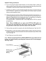
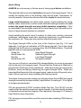
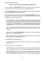
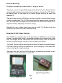
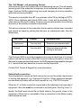
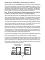
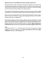
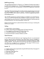
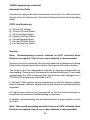
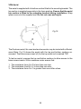
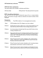
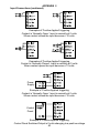
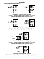
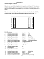
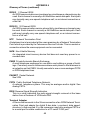
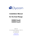
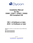
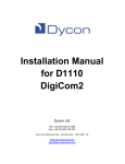
Installation Manual
for CS1000 / CS1001
VDN DualCom Mk1 & 2
CSL Dualcom Limited
Tel: 01895 474 474
Fax: 01895 474 440
INDEX
Product Description
Part Numbers
2
3
What to Do:
Site Survey
Installation
System Testing
Troubleshooting
Help Desk & Web Site
5
6
7-8
9 - 10
10
The Details:
Aerial Siting
VDN Direct Check
Inputs & Self Learning
Dualcom Mounting
CS1051 & CS1052 Radio Test Set
Dualcom Polling
ESN & NUA Numbers
Dualcom Registration
Using the CS1050 Expander Board
Outputs
Telephone Line Connection
Analogue PSTN Telephone Line Connection
PABX Connections
ISDN, ISDN2, ISDN2e
Home Highway, Business Highway
ISDN30
ADSL or ‘Broadband’
The ‘Call Minder’ call answering service
Safety Earth connection
System Power, Internal Battery & Power Saving
NVM Programming, Line Monitoring
Up/Downloading Security
Aerial Testing
Appendix 1 ( LED Indications )
Appendix 2 ( Inputs & Triggering)
Appendix 3 (Plug-on Dualcom)
Appendix 4 ( Specification )
Appendix 5 ( Regulations & Approvals )
Appendix 6 ( Glossary of Terms )
1
11 - 12
12
13
14
14 - 15
15
16
17 - 18
19
20
21
21 - 23
24
25 - 26
27
27
28
29
29
30 - 32
33 - 34
34
35
36 - 38
39 - 41
42 - 43
44
45
46 - 49
Part No: AH 100001-008 12/4/2006
VDN DualCom Mk1 and Mk2
Installation Manual
Description
VDN Dualcom is an advanced auto-dialling Digital Communication Device for
secure alarm reporting. It can transmit alarm signals to an Alarm Receiving
Centre using the PSTN (Public Switched Telephone Network) or VDN (Vodafone
Data Network).
When Dualcom is triggered by the alarm system it initiates calls to the Alarm
Receiving Centre over both communication paths simultaneously. Once it has
received an acknowledgement signal from one path it clears the calls on both
paths so that the Alarm Receiving Centre receives only one alarm notification.
Test calls are delivered using both paths to test the system fully.
Dualcom monitors both communication paths continuously. A fault on one path
is reported to the Alarm Receiving Centre using the other functioning path. Any
Alarm System bell delay is maintained unless both paths are in fault, or the
Alarm Abort feature (if programmed) is used.
Dualcom includes an internal battery that ensures continued reporting and
monitoring even in the event of a total power failure to the Dualcom.
Dualcom comes complete with Alarm Abort feature to enable older alarm systems to comply with the ACPO false alarm policy. Once the system is set, if a
mis-operation occurs and the system is unset within 90 seconds, a restore on
channel 3 or separate code will be sent to the Alarm Receiving Centre. If programmed, a Tellback will also reset the control panel.
Dualcom is available in two versions; Stand alone and Plug-on. A tamper protected steel box with an integral 1 amp power supply is also available. Dualcom
is housed in an ABS plastic case which protects the electronics and meets
PSTN safety requirements. Dualcom has 8 alarm inputs. This can be expanded
to 16 by adding a plug-on module which also provides 8 outputs. For part numbers of these accessories, see over.
Note: Throughout this manual the Paknet data communication network operated by Vodafone is referred to as the VDN (Vodafone Data Network).
2
Part Numbers
CS 1000-20 VDN Dualcom Mk2 Stand Alone (including aerial).
CS 1001-20 VDN Dualcom Mk2 Plug On (including aerial).
CS 1050
Expansion to 16 inputs & 8 outputs.
CS 1500
Tamper protected box with 1 amp Power Supply.
CS 1051
Installers VDN Signal Strength Test Set
CS 1052
Wireless Signal Strength Meter for use with CS1051
CS 1053
High-gain Aerial
CS 1054
Downloading software and NVM Programmer
CS 1055
Pack of 10 NVM EEproms
CS 1056
10m VDN aerial extension lead
CS 0300
Heavy Duty Lightning/Surge Suppressor
CS 0380
Replacement Internal Battery for VDN Dualcom Mk2
CS 0700
ISDN - Analogue Converter
CS 0402
CSL Products CD with manuals for all products
There is a lot of technical information in this manual. For trouble-free
installation it is essential to follow the site survey and installation recommendations on pages 5-8.
3
Red & Green Signal
Strength LEDs
Red & Yellow
Communication
LEDs
Aerial
Connector
Telephone
Line
Terminals
(under)
NVM
VDN Dualcom Mk1 Stand Alone
Fig 1
Battery Cover
Red & Yellow
Communication
LEDs
Battery Cover
Screw
Internal
Battery
Socket
Yellow
Service LED
Red & Green Signal
Strength LEDs
Fig 2
Aerial
Connector
VDN Dualcom Mk2 Stand Alone
4
Telephone
Line
Terminals
(under)
Site Survey
It is strongly recommended that a Site Survey is conducted prior to installation of a VDN Dualcom to confirm that adequate VDN signal strength
is available at the site.
Call a Help Desk. See page 10. Ask for a VDN signal strength prediction. For
this, you will need to have the Post Code of the site available. This will tell you
if there is VDN radio coverage at the proposed site.
If there is no VDN radio coverage at the proposed site, the Dualcom’s VDN
alarm reporting path will not operate. If your GSM mobile telephone operates at
the site you could consider using a CS2000 GSM Dualcom. Contact CSL for
more information.
You can use a Dualcom, aerial & fully charged battery to survey the proposed
site for the point of strongest signal. You can also use a portable CS1051 or
‘Pakit’ test set to show the VDN signal strength at the proposed site.
See Page 11 ‘Aerial Siting’ for more information. Make a note of this point and
use it when installing the Dualcom aerial.
Red & Green Signal
Strength LEDs
Socket for
Expansion units
Yellow
Service LED
Power Switch
12 volt power
or Jumper Link
connections Internal
Battery
Earth
Socket
On
Off
Pin 1
Positive (pull-up) and Fault relay
0volt source for input
terminals
triggering
Aux relay
Test
8 input terminals
terminals
Pins
NVM socket
VDN Dualcom Mk2
Fig 3
5
Reset
Pins
A1 & B1
terminals
PSTN Line
A & B terminals
Installation
1. Assemble the aerial by screwing the metal rod and the flexible aerial into the
mounting bracket. Site the aerial vertically at the point of strongest signal
ensuring that it is within the protected area. This is usually the highest point
in the building and will have been identified during the site survey. Avoid
metal roofs or installation within metal skinned buildings. See Page 11, 12
& 35.
2. Totally power down the control panel mains and battery.
Where required, fit the CS1050 Expansion Board. See page 19.
3. Program the NVM for the system requirements or obtain a programmed
NVM from your ARC. See page 33. Fit the NVM into the 8 pin socket on the
Dualcom. (NVM indent towards the Service LED). See Fig 1 and 2.
4. If you are installing a CS1001 Plug-On Dualcom, plug the unit onto the
control panel pins ensuring they are correctly aligned.
5. If you are installing a CS1000 Stand Alone version of Dualcom, connect the
input triggers. See Appendix 2.
6. Connect to the relays “Fault” and “Aux” as required. See page 20.
7. Connect the aerial to the Dualcom aerial lead using the threaded connector
provided. See Fig 1 and 2.
8. Connect the PSTN line to the terminals provided under the protective cover.
Only ‘serial connection’ is recommended for other equipment using the same
telephone line as Dualcom in security installations. See Pages 21 to 29.
9. Dualcom Mk2, ensure that the Power Switch is in the Off position or that
the Power Jumper is removed. See Fig 2.
10.Dualcom Mk2, connect the internal battery onto pins provided. See Fig 2.
11. On both CS1000 Stand-Alone and CS1001 Plug-On Dualcom, connect the
‘12v +’ & ‘12v -’ terminals to the Control Panel or Power Supply 12 volt
output (e.g. Aux supply’ or ‘DC power). See Fig 1 & 2 and page 30-32.
The installer must ensure that the Alarm System power supply is rated to
provide adequate power. Dualcom requires a minimum of 230mA.
12.Note the Dualcom ESN & NUA numbers, security access numbers, etc.on
the site records that will be stored at your office. See Fig 4 and page 16.
See also Polling, page 15.
13. The Dualcom is now ready for testing.
6
System Testing
Ensure you have informed your Alarm Receiving Centre that you are ready
to test your Dualcom Product.
1. Reconnect the mains supply to the control panel.
2. Dualcom Mk2. Move the Power Switch to the On position (See Fig 2).
Note that the power switch may be a yellow slide switch or a removable
jumper link. This will power-up the Dualcom and ‘register’ it onto the VDN
network. Registration will take about 45 seconds with the Radio LED On,
the SERVICE LED flashing and the Signal Strength LEDs Off. See page 17.
Whenever you apply power to the Dualcom (using the Power Switch/Jumper
or by shorting the Reset pins) during installation or during a regular maintenance visit, the Dualcom will ‘register’ onto the VDN network. See page 18.
Dualcom Mk1. Press and hold the black TEST button. Connect power to
the Dualcom. Keep the TEST button held until the SERVICE LED starts to
flash. Release the TEST button. See page 17 and Fig 6.
Note: If the NVM is an incorrect type, faulty, fitted incorrectly or has been
incorrectly programmed, the Red and Yellow Communication LEDs will flash
alternately. If there is a problem with the VDN radio path, the Yellow Communication LED will flash. If there is a problem with the PSTN telephone
line, the Red Communication LED will flash. See Appendix 1 for LED fault
indications.
4. To test both reporting paths to the ARC, momentarily short the Test pins on
the Dualcom see Fig 1 and 2. This will cause Dualcom to send a test signal
to the ARC on both the PSTN telephone path and the VDN radio path.
Once the test pins are shorted, the two communication LEDs will illuminate, (Red for PSTN and Yellow for Radio). During communication the LEDs
will indicate the progress of the call, see Appendix 1. When a path has
successfully communicated with the ARC its associated LED will go off.
During Test calls (started using the Test pins), both paths will send a test
call. The ARC should receive two test calls.
Ensure after the test that both Radio and PSTN LEDs are off; this will mean
that the test calls on both paths are complete.
5. Now trigger all the used inputs on the Dualcom. This should be done by
Setting the Control Panel and triggering an alarm condition. If P/A or Fire
circuits are being monitored these should also be triggered and tested.
7
System Testing (continued)
6. If you are using the Alarm Abort feature, set the Alarm Panel, initiate an
alarm condition and (If the alarm system incorporates bell delay this will be
overridden) unset the alarm system within 90 seconds.
7. Contact your ARC to confirm that all signals have been received. Ensure
that all ‘Restore’ signals are received when the Dualcom input terminals
return to their quiescent value.
8. If the quiescent (non-active) states of the input terminals are incorrect, i.e.
‘positive applied/removed is inverted, then the ARC will report that the Alarm/
Restore or Open/Close is the ‘wrong way round. To correct this, on Dualcom
Mk2, use the Self Learning Input feature. See page 13.
For Dualcom Mk1, contact the ARC or the Help Desk at CSL for remote
programming.
Note : When ALARM calls are made, both PSTN & VDN paths are
activated, but only ONE alarm call will be received. This will be from
the path that is the first to send the alarm call to the ARC.
9. If at any time you wish to cancel a call, short the Reset pins. See Fig 1 & 2.
10.Remember to note the Dualcom ESN & NUA numbers (and any security
access numbers) on the site records that will be stored at your office. See
Fig 3 and page 14.
11. Your Dualcom is now fully tested.
Note: When transporting Dualcom Mk2 ALWAYS disconnect the internal
battery to stop the battery operating the Dualcom until it is discharged.
See Fig 2 and 3.
Internal Battery
ESN Number
(under internal
battery)
VDN Dualcom Mk2
Fig 4
8
Troubleshooting
Q. What if the VDN radio path signal has not been received by the Alarm
Receiving Centre ?
Check that the NVM is fitted & has been correctly programmed.
Check with a meter that the voltage supply to the Dualcom is 12v or more
and does not dip when the Dualcom is signalling.
Check, using the Signal Strength LEDs (Red & Green) or the CS1052 that
the radio signal is sufficient and the VDN path status = OK.
Contact a Help Desk or use Direct Check to measure the signal strength
that is received at the base station.
Check the aerial for connection and insulation.
See Appendix 1 for VDN fault indications. These will help diagnose radio
path problems.
Q. What if the Telephone Path signal is not received by the Alarm
Receiving Centre ?
Check that the NVM is fitted and has been correctly programmed, i.e.
PSTN enabled, correct telephone numbers etc.
Check that the PSTN line is properly connected. Check with a meter that
approximately 50 volts DC is present across the PSTN terminals marked A
and B. Connect a telephone to the PSTN line and make a call to the ARC
to ensure that the PSTN line is fully functional. Remove telephone after
test.
Disconnect any other equipment that is using the same PSTN line to ensure that it is not inhibiting the Dualcom.
Check that when the Digital Communicator is triggered, the voltage across
the A and B terminals drops to between 6 and 12 volts DC.
Ensure that ‘call barring’ to the ARC Receiver telephone number has not
been set on the PSTN line used by Dualcom.
See Appendix 1 for Line Monitoring indications. These will help diagnose
line problems.
9
Troubleshooting (continued)
Q. What if there appears to be random triggering of the Dualcom ?
Ensure that 0 volts is common across all parts of the alarm system.
If the Dualcom receives its power from a Power Supply that is additional to
the alarm system, ensure that the 0 volt connection on the additional power
supply is connected to the 0 volt connection on the alarm system.
Q. What if up/downloading does not work ?
Check that the NVM is fitted and has been correctly programmed.
Ensure that the CS1052 Plug-on Wireless Signal Strength Meter is not fitted to the Dualcom.
Help Desk
If you have installed the Dualcom in accordance with these instructions, checked
all the above points but are still experiencing problems you can contact your
Dualcom supplier, your Telecom Service Provider or your VDN Service Provider.
Please have your ESN number to hand. See Fig 1 & 2 and page 16.
In UK, VDN network questions may be addressed to:
The Vodafone VDN Help Desk:
Tel:
08700 700 600 (Option 2 = Help Desk Operator)
In UK, Dualcom installation, programming, operation or other questions may be
addressed to:
The CSL Technical Support Desk:
Tel:
01895 474 444
Email: [email protected]
The CSL web site: www.csldual.com contains the latest copies of all manuals
for all CSL products. Please ensure that you are working from the latest version. You can also download associated information and software samplers.
Sales, shipping and contact information is here too.
A CD is available that contains all manuals for all CSL products and the programming software for Dualcom. Contact CSL Technical Support for more information.
10
Aerial Siting
ALWAYS do a site survey to find an area of strong signal before installation.
The aerial should be mounted vertically at the point of strongest signal. This is
usually the highest point in the building (often the loft area). Remember, for
security reasons, the position chosen should be inside the protected area.
Large metal structures can affect radio signals. Avoid installing the aerial
directly under metal roofs or within metal skinned buildings because this will
reduce the signal strength and may inhibit operation completely. If this
is unavoidable, the strongest signal will be found away from the metal roof or
close to large external windows or skylights.
Avoid installing the aerial close (2 metres) to cable runs, ducting, structural
metalwork, metal pipes, water tank, electronic equipment, e.g. photocopiers,
fax machines etc. These can have similar effects as metal roofs.
The Signal Strength LEDs on the front of the Dualcom (see Fig 1 & 2 and
Appendix 1) will give an indication of FSSI signal strength. This is the signal
strength that the Dualcom is receiving from the VDN Base Station. These will
not work with an unprogrammed NVM.
Green On:
High Signal Strength
Red & Green On:
Medium Signal Strength
Red On:
Low Signal Strength
Red & Green Off
No signal available.
You can use a Dualcom, aerial and fully charged battery to survey a proposed
site for the point of strongest signal. Ensure that the Dualcom is fitted with a
programmed NVM and is fully operational. Walk around the site carrying the
Dualcom, aerial and battery observing the signal strength LEDs. When you
have identified the point of the strongest signal, make a note of this point (accurate to 20cm) and use it when installing the Dualcom aerial.
To achieve a more accurate reading, we strongly advise that a RSSI test (signal
strength received by the base station) is performed. A reading of +15 or higher
is strongly recommended.
CSL can provide the CS1051 Installers Radio Test Set. The CS1051 may be
used to align the aerial for maximum signal strength. It will also identify sources
of interference and test the integrity of the radio path. See page 14. Contact a
Help Desk for more information.
CSL strongly recommend the use of this test unit when installing VDN Dualcom
products.
11
Aerial Siting (continued)
Reliable operation is unlikely with a low signal strength. If the signal strength
LEDs, RSSI or FSSI readings show that the signal strength is low, you should
improve the signal strength. This may be achieved by repositioning the aerial or
fitting a higher gain aerial (CSL part number CS1053).
Where the aerial has to be installed some distance from the Dualcom a 10m
aerial extension lead is available (CSL part number CS1056).
To check the RSSI, choose one of the following options. In all cases please
have the Dualcom ESN to hand before phoning. This may be found on a label on
the Dualcom, under the battery on Dualcom Mk2 and on the end label of the
Dualcom packaging. See Fig 1 and 2.
1.
2.
3.
4.
Phone the automated Direct Check service on 08704 505 805 (see below).
Use the CS1051 Radio Test Set. See page 14.
Phone the Vodafone Data Network Help Desk. See page 10.
Phone the CSL Technical Support Desk. See page 10.
Remember: It is always easier to find the point of strongest signal before the
equipment is fitted to a wall. Moving aerials, cables, trunking etc. after installation is wasted time and effort.
VDN Direct Check
A telephone service called Direct Check is available that will tell you the RSSI
signal strength of a registered Dualcom. Direct Check is an automatic service
that you control using a telephone keypad or speech commands. All calls are
charged at the UK standard ‘b’ rate.
To use Direct Check:
1. Note the ESN of the Dualcom, See Fig 4.
2. Make sure that the aerial is assembled correctly, stationary, vertical and
that the Dualcom is powered correctly.
3. Dial Direct Check on 08700 700 600
4. Select ‘signal strength checking’ using the keypad or by speaking into the
telephone and then enter the ESN number in the same manner.
5. The signal strength will be spoken to you.
12
Inputs and Self Learning
For full Inputs connection information see Appendix 2.
To aid installation, Dualcom Mk2 can learn the quiescent state of its inputs,
i.e. the ‘not active’ state, without having to re-program the NVM.
Note: Dualcom Mk1 does not have self learning inputs. Contact the ARC or
the CSL Help Desk for remote programming.
Self Learning allows the unit to be programmed during installation with ‘positive applied’ or ‘positive removed’ inputs. It will correct NVMs that have been
supplied with incorrect input polarities.
1. Setup the inputs ‘non-active’ conditions by connecting a positive voltage or
‘no’ voltage (0v) on each input terminal as required. This is easily achieved
by connecting the control panel outputs to the Dualcom inputs, then put the
control panel in the day state with no activated detectors and all alarm
conditions reset. You can leave any unused Dualcom inputs disconnected.
‘Non-active’ means that the voltage on the alarm inputs are in the ‘not in
alarm’ condition and open/close inputs are in the ‘open’, ‘unset’ or ‘day’
condition.
Ensure that the unset/open/day state is selected on the Control Panel,
not the ‘set’ or ‘engineering’ states.
3. With the Dualcom powered-up, apply a permanent short to the Test pins
with a jumper link or screwdriver blade etc.
4. Momentarily short the Reset pins.
The Red & Yellow LEDs will flash: 4 Red...4 Yellow...4 Red...etc. indicating
‘learning’ mode.
5. Remove the short on the Test pins.
The LED flashing will cease and the state of the 8 inputs will be remembered
as the ‘non-active’ condition. This information will be stored in the NVM.
Note: DO NOT park the Jumper Link onto BOTH Test pins because
this will immediately trigger a test call and inhibit further operation.
13
Dualcom Mounting
Dualcom is available as a ‘stand-alone’ or ‘plug-on’ version.
The plug-on version is specifically designed for fitting to Control Panels that are
equipped with standard communicator mounting pins. Contact the CSL Technical support Desk for the latest list of Control Panels that may be used. See
Appendix 3.
The stand-alone version of Dualcom may be mounted in a boxed power supply
or other suitable case. The CS1500 boxed one-amp power supply is ideal for
this. The case has mountings and screw retainers for a Dualcom, space for a 7
amp/hour battery and plenty of room for wiring.
Alternatively, any suitably sized case may be used. The Dualcom has two
mounting lugs fitted to its case for screw fixing.
Using the CS1051 Radio Test Set
The CS1051 is a complete test set for all aspects of VDN radio, convienently
housed in a rugged brief-case. It is supplied complete with all connectors, mains
and car charger, aerials, manual and a 25 minute training video. An optional
Wireless Signal Strength Indicator is also available. See below.
The Radio Test Set may be used to align the aerial for maximum signal strength.
It will also identify sources of interference, test the integrity of the radio path,
and provide signal strength readings.
The use of this Test Set for all VDN Dualcom installations is strongly recommended. For more information, contact CSL.
CS1052 Wireless
Signal Strength Meter
CS1051 Radio Test Set
Fig 5
14
CS1052 Wireless Signal Strength Meter
The CS1052 may be used with the CS1051 Radio Test Set to align the aerial for
maximum signal strength.
This small hand-held unit allows the aerial to be aligned even when the Radio
Test Set is connected to the aerial lead at the Dualcom’s location and the aerial
is located in another part of the building. See Fig 5.
The use of this optional addition to the Radio Test Set is strongly recommended.
For more information, contact CSL.
Dualcom Polling
In addition to Dualcom continuously monitoring the VDN radio path to its base
station, the VDN network regularly tests communication with every Dualcom.
This is called polling.
If polling detects that there is a communication failure, then the relevant ARC
will be allerted, enabling corrective action to be taken. Polling failure may also
be reported after an extended power failure to the Dualcom. see page 30-32 for
details.
To enable any problems to be quickly and correctly resolved, you should:
1. Ensure that the ARC is kept informed of new and replacement installations
and the ESN & NUA numbers of the equipment that is installed.
2. Ensure also that the installers details are correctly recorded at the ARC.
All Dualcom products are normally polled hourly by the VDN. Polling failure will
be reported to the relevant ARC directly onto their polling RPM (or FEP) equipment or by a fax from Vodafone.
Contact your ARC or a Help Desk for more information.
15
ESN Number
An ESN number uniquely identifies each Dualcom. It is the Electronic Serial
Number. It is like the ‘chassis number’ on the metal chassis of a car.
On Dualcom Mk1, the ESN number number may be read from a label on the
outside plastic case of the unit.
On Dualcom Mk2, the ESN number number may be read from the label that is
under the internal battery. To access it, remove the battery-cover screw, lift the
tab at the front of the battery cover and lift out the battery. See Fig 2.
On Dualcom Mk2, to replace the battery, position the red and black wires in the
lid cut-out, clip the back of the battery lid onto the Dualcom, lower the lid tab
and replace the screw.
NUA Number
The NUA number identifies the user that the Dualcom is registered to. It is the
Network User Address. It is like the Registration Plate (Number Plate) on the
front and back of a car.
If one number is known then the other may be found from records at CSL or
Vodafone. These may be obtained by calling a Help Desk. See page 10.
It is strongly recommended that the Dualcom ESN & NUA numbers, security
access numbers, etc. are recorded on the site records that will be stored at
your office. See Fig 2.
16
Dualcom Mk1 Registration
These Registration instructions are for VDN Dualcom Mk1 only.
Dualcom must be ‘registered’ onto the VDN communications network before
use. If un-registered, Dualcom can not send alarms to the Alarm Receiving
Centre via the Paknet network and ‘up/downloading’ will not operate. Signal
strength readings may also fail or be incorrect.
Always re-register the Dualcom whenever it is moved to a new location and
during regular maintenance visits. To register Dualcom Mk1 follow the steps
below:
1. Remove power from Dualcom Mk1.
2. Push and hold the TEST button on the end of Dualcom Mk1. See Fig 1 and
6.
3. Keep the TEST button pushed, and connect power to Dualcom Mk1.
4. Keep the TEST button held for a further 5 seconds or until the SERVICE
LED next to the TEST button starts to flash. You may now release the TEST
button.
5. The SERVICE LED will continue to flash for about 25 seconds. It should
then remain on solid. This indicates that registration is complete and Dualcom
Mk1 is ‘locked’ onto a VDN base station.
If the SERVICE LED does not remain on solid after 25 seconds, registration
has failed. This is normally due to low (or no) signal strength. If the site survey
and radio signal strength prediction (see page 4) indicated a suitable signal
strength, check the aerial connections, power supply, signal strength LEDs
and then repeat the registration procedure.
During registration:
1. Dualcom logs (up to 14) base stations that it can hear.
2. Dualcom will ‘lock’ onto the base station with the strongest signal.
3. The VDN network enables the Dualcom to send alarms.
All of these three functions must be completed before registration is successful
and signals can be passed to the ARC.
Fig 6
17
Dualcom Mk2 Registration
These Registration instructions are for VDN Dualcom Mk2 only.
Whenever you apply power to the Dualcom by:
a). Moving the Power Switch to the On position.
b). Connecting the power supply and pluging-in the internal battery.
c). Briefly shorting the Reset pins.
the Dualcom will ‘register’ onto the VDN network.
Moving the Power Switch to the Off position will disconnect the external supply
and the internal battery thus fully powering-down the Dualcom.
Always re-register the Dualcom (by briefly shorting the Reset pins) whenever
it is moved to a new location and during regular maintenance visits. Re-registering allows the Dualcom to recognise any new base stations that may have
been commissioned in your area.
To register a Dualcom:
1. Connect power to Dualcom or briefly short the Reset pins.
2. The SERVICE LED will start to flash and the VDN LED will be on solid. The
SERVICE LED will continue to flash for about 45 seconds. It should then
remain on solid and the VDN LED will go off. This indicates that registration
is complete and Dualcom is ‘locked’ onto a VDN base station.
If the SERVICE LED does not remain on solid after 45 seconds, registration
has failed. This is normally due to low (or no) signal strength. If the site survey
and radio signal strength prediction (see page 5) indicated a suitable signal
strength, check the aerial connections, power supply signal strength LEDs and
then repeat the registration procedure.
During registration:
1. Dualcom logs (up to 14) base stations that it can hear.
2. Dualcom will ‘lock’ onto the base station with the strongest signal.
3. The VDN network enables the Dualcom to send alarms.
All of these three functions must be completed before registration is successful
and signals can be passed to the ARC.
Occasionally during installation it may be necessary to ‘Force Register’ a Dualcom. If this action is required you will be informed by a Help Desk. Following
Force Registration you must NOT move the Power Switch to the Off position for 24 hours, and you must NOT disconnect the internal battery for
24 hours. The external power to Dualcom may be removed for short periods
and re-connected as required during the 24 hour period.
18
Using the CS1050 Expander Board
The CS1050 is a plug-on board that adds an additional 8 inputs and 8 outputs
to the CS1000 and CS2000 range of Dualcom units.
To install:
1. Remove power to the Dualcom when fitting or removing the CS1050 Expander
board.
2. Slide the CS1050 Expander into the two guides on the Dualcom with the
white connector towards the Dualcom board. Push the CS1050 down to
ensure it connects fully to the Dualcom.
3. Connect the triggering inputs to the INPUT terminals labelled 9 to 16, as
required. See page 13 and Appendix 2.
4. Connect the outputs to the OUTPUT terminals, labelled 1 to 8, as required.
These outputs are ‘open collector pull-down to 0v. Each will supply up to
50mA and may operate lights or relays with a supply up to +28 volts. Where
relays are used, they should be fitted with a diode across their coil to reduce
‘back EMF’ voltages. See Fig 7.
Note: If you use a seperate Power Supply, remember to connect the 0v
terminals of all of the parts of the system.
Relay
+VE
Diode
Power
Supply
CS1050
o/p
0v
0v
Fig 7
The Dualcom NVM will need to be programmed for ‘16 channels’ enabled. Your
ARC will normally provide a programming service. If a programming service is
unavailable, contact the CSL Technical Support Desk. See page 10.
All of the normal input programming options apply to the CS1050 Expander.
These are: Positive applied / removed triggering, self learning, restore reporting,
open/close reporting, VDN failure report, PSTN failure report and alarm abort.
19
Fault Output
The fault relay contacts, C, NO and NC operates if the PSTN line is cut, the link
to the Paknet base station signal is lost, after 3 unsuccessful call attempts are
made on the PSTN or 10 unsuccessful attempts are made on the VDN.
Fig 8 details the Fault Relay operation in these various situations.
Fault
PSTN fault only
VDN fault only
Both PSTN & VDN
3 attempts on PSTN
10 attempts on VDN
Total fail PSTN & VDN
Panel Day
Panel Set
Panel Alarm
Continuous
Continuous
Continuous
2 sec pulse
2 sec pulse
Continuous
2 sec pulse
2 sec pulse
Continuous
2 sec pulse
2 sec pulse
Continuous
Nothing
Nothing
Continuous
2 sec pulse
2 sec pulse
Continuous
Fig 8
Aux Output
The Aux relay contacts, C, NO and NC can be programmed to :
a) Change state if a tellback signal is generated by the alarm abort sequence
or is sent to Dualcom from a remote centre using the CS1054 Programming
and Downloader software.
b) Change state when Dualcom has successfully communicated with the ARC.
Note: On the Plug On version, these terminals are not fitted and the
relevant signals are automatically fed via the plug-on pins to the control
panel.
If the CS1050 Expansion module is fitted, a 8 further outputs are provided. See
page 19. These can be remotely controlled via the VDN radio path using the
CS1054 Downloading Software.
For a full list of programmable features see instructions for the CS1054
Dualcom Programmer.
20
Telephone Line Connection
There are several different types of telephone line available from service providers.
DigiCom, Dualcom, the CSL range of Control Panels and most other intruder
alarm equipment requires an analogue telephone line connection. ‘Earth Loop
Calling’ or ‘Earth Calling’ types of analogue telephone line can not be used.
Equipment that requires an analogue line can not be connected directly to
digital ISDN or digital or hybrid ADSL telephone lines.
Details of these lines and connections follow.
Analogue PSTN Telephone Line
The analogue PSTN is a communication network where the line from the exchange equipment and the service supplied to the subscriber is ‘analogue’, i.e.
not ‘digital’.
A telephone line is always terminated at the users premises by an NTP (Network Termination Point) which is provided by the Telecoms Service Provider.
This is a socket or connection where the users equipment can be connected.
Some NTPs provide a socket and terminals for connection. In many cases,
the NTP operates using power supplied from the exchange equipment via the
telephone line. See Fig 9.
An analogue PSTN telephone line may be provided by BT or any of the other
44 telecomms service providers in UK. Dualcom can be connected to this analogue line. See Fig 9. Refer also to the ‘safety Earth’ and the ‘Call Minder’
sections.
Analogue PSTN Telephone Line
Fig 9
21
PSTN Line Connection Options
Dualcom’s line connection requires an analogue telephone line. For connection to other types of telephone line, refer to the previous pages.
Connecting other telecoms equipment IN PARALLEL to the analogue
telephone line used by Dualcom (or any Digital Communicator) can stop
the unit sending alarm calls to an Alarm Receiving Centre. Parallel
connection is NOT recommended for Dualcom when it is used in a security system.
There are several ways that a Dualcom may be connected to a PSTN telephone
line particularly when other equipment needs to share the same telephone line.
Some require that your Telecom Service Provider supplies particular line features. Some require NVM programming options. Refer also to the ‘Safety Earth’
and the ‘Call Minder’ sections.
The highest security PSTN line for Dualcom (Recommended):
A PSTN line supplied as ‘outgoing calls only’, i.e. Incoming Ringing Barred,
AND the PSTN line is ex-directory,
AND the PSTN line goes to the Dualcom ONLY. Other equipment can be
connected to the Dualcom A1 & B1 terminals (i.e. series connection) to make
outgoing calls only. See next page.
The next best security option for a PSTN line (Recommended):
A PSTN line supplied with the ‘3-way calling’ feature,
AND the Dualcom NVM is programmed for ‘3-way calling’,
AND the PSTN line goes to the Dualcom ONLY. Other equipment can be
connected to the Dualcom A1 & B1 terminals (i.e. series connection) for incoming and outgoing calls. See page 21.
The ‘no security’ option ( !!! NOT Recommended !!! ):
A PSTN line supplied without ‘outgoing calls only’ or the ‘3-way calling’ feature.
This option can not cancel or ‘hold’ incoming calls and these will inhibit Dualcom
from making a telephone call to the Alarm Receiving Centre.
The ‘parallel connection’ option ( !!! NOT Recommended !!! ):
The Dualcom A & B terminals connect to the telephone line,
AND other equipment connects directly to the same telephone line.
This connection option can not cancel or ‘hold’ incoming or outgoing calls and
these will inhibit Dualcom from making a telephone call to the Alarm
Receiving Centre.
22
PSTN Line Connection (Dualcom alone on line)
Your Telecom Service Provider should be asked to supply and fit an analogue
line and an NTP with terminals near the alarm system. The alarm installer
should then follow steps 1, 2 and 4 below. See Fig 10.
Note : If Dualcom is connected to the PSTN line and a telephone or other
equipment is sharing the same line (Parallel Connection) the bell in the telephone may tinkle when Dualcom is operating. Dualcom alarm calls to the
Alarm Receiving Centre will also be inhibited. See previous page.
Series Connection (Dualcom & other equipment on line)
Your Telecom Service Provider should be asked to supply and fit an analogue
line and an NTP with terminals near the alarm system. The alarm installer
should then follow steps 1 - 4 below. See Fig 11.
1. Use cable type 1/0.5mm CW1308, feed through the cable entry, connect
the cores to the Dualcom terminals marked A and B.
2. Connect the other end of the cable to the Terminal Block connections for the
incoming telephone line, marked A & B, or 2 & 5.
3. If the PSTN line used by Dualcom is shared with other apparatus (e.g. telephone, fax or answer machine) connect the terminals marked A1 and B1
on the Dualcom to a PSTN Socket. (Terminals 1 & 6 in the NTP can be used
as ‘loop in points’ for this purpose). The customer may then plug their phone,
fax etc, into that socket.
4. On Dualcom and other equipment with an Earth or ‘E’ terminal, connect a
1.0mm earth cable to Terminal E. Ensure that the other end of this earth
cable is connected to a good ground earth. This protects the equipment
from high voltages, e.g. lightning, that may strike the telephone line. Refer
also to the ‘Safety Earth’ section.
Dualcom
Dualcom
PSTN
Terminal
Block
To Earth
Other
Apparatus
2
3
4
5
PSTN
Terminal
Block
To Earth
2
PSTN
Line
2
3
3
4
4
5
5
6
Fig 10
6
23
Fig 11
PSTN
Line
PABX (Private Automatic Branch Exchange)
A PABX is a telephone exchange in one business or building (where a dial 9 is
needed for an outside line). It connects to one or more outside telephone lines
and has two or more extentions within the business or building. See Fig 12.
Dualcom may be connected to one of the outside telephone lines where they
are the analogue PSTN type.
The extentions within the building may be analogue or digital. Where an extention
is analogue, a normal phone or fax machine may be connected. Dualcom can
be connected here and programmed to dial a 9. See Fig 13.
Where the extention is digital it is often to the ISDN standard or is a special
digital standard that is particular to the manufacturer of the PABX equipment.
Where a special digital standard is used, then a special ‘feature phone’ is
usually required, provided by the manufacturer of the PABX equipment.
Dualcom can not be directly connected to any type of digital telephone line.
Refer also to the ‘Safety Earth’ and the ‘Call Minder’ sections.
PABX with connection to Analogue PSTN Line
Fig 12
24
PABX with Analogue extension
Fig 13
ISDN (Integrated System Digital Network)
The digital ISDN is a communication network where the line from the exchange
equipment and the service supplied to the subscriber is ‘digital’, i.e. not ‘analogue’.
An ISDN line is a digital telephone line that conforms to the international ISDN
standard. It can carry several calls simultaneously. A ‘basic rate’ ISDN telephone line can carry the equivalent of two simultaneous calls. In UK, a ‘basic
rate’ ISDN line is called ISDN2 or ISDN2e. A ‘primary rate’ ISDN line can carry
the equivalent of up to thirty simultaneous calls. In UK, a ‘primary rate’ ISDN
line is called ISDN30.
An ISDN line is always terminated at the users premises by an NTP (Network
Termination Point) which is provided by the telecoms Service Provider. The NTP
is a socket or connection where the users equipment can be connected.
The service supplied to the user from the NTP may vary. The digital connection
on the NTP is called the S-Bus. The S-Bus allows many different types of
digital communication equipment to be connected, e.g. an ISDN interface card
in a PC.
In many cases, the ISDN NTP operates using power supplied from the exchange equipment via the ISDN telephone line, however some types of NTP
may require a connection to the mains supply at the users premises. Some
ISDN NTPs include a converter to provide analogue sockets (e.g. Home Highway); See below.
25
ISDN2e (Integrated System Digital Network, 2 channel)
A ‘basic rate’ ISDN telephone line can carry the equivalent of two simultaneous
calls. In UK, a ‘basic rate’ ISDN line is called ISDN2 or ISDN2e. Some suppliers call an ISDN2e line ‘Home Highway’ or ‘Business Highway’. See below.
Where an ISDN2 line is fitted but an analogue line is required, e.g. for Dualcom,
then the CSL CS0700 ISDN-Analogue converter may be used. The CS0700 has
some important features especially for security communications including override’ line grab’. Refer to the CS0700 manual and see Fig 14.
Dualcom can not be directly connected to a digital telephone line.
An ISDN2 line can be provided as ‘point-to-point’ or ‘point-to-multipoint’. Where
there is only one item connected to the S-bus then a ‘point-to-point’ service is
OK. Where two or more items are connected to the S-bus then a ‘point-tomultipoint’ must be provided.
ISDN2 Line + CS0700 Converter
Fig 14
Home Highway, Business Highway
Home Highway or Business Highway is the marketing name for a ‘basic rate’
ISDN2 line supplied by BT with an NTE9 NTP.
The NTE9 NTP provides two S-Bus sockets, it includes an ISDN-Analogue
converter and two analogue telephone sockets. This type of NTP can have an
analogue phone, fax, modem etc.connected at either or both of the analogue
telephone sockets. Dualcom may be connected to these analogue connectors.
See Fig 15.
Power for the NTE9 comes from the exchange equipment via the ISDN line and
also from the mains supply at the users premises.
26
Home Highway, Business Highway (continued)
In the event of mains failure, the right-hand analogue telephone socket on the
NTE9 will cease to operate but all other functions are powered from the exchange equipment. It is important therefore to connect Dualcom to the left-hand
analogue telephone socket on the NTE9. See Fig 15.
A maximum of two calls on an NTE9 may be in progress at the same time. Use
of one analogue telephone socket constitutes one call. Use of the S-Bus on
either S-Bus socket constitutes one or two calls (64 or 128 K byte bandwidth).
If two calls are in progress it is impossible to make another outgoing call or
receive another incoming call.
The ‘two call maximum’ means that if either of the S-Bus sockets are being
used and a telephone call is in progress on one analogue socket, then anybody
ringing into the other analogue telephone socket will get a ‘busy’ signal. Equally
any connection to the other analogue socket, e.g. a telephone at the user’s
premises, will not hear the dialling tone and will not be able to dial out. Note that
an over-ride ‘line grab’ facility does not exist on an NTE9.
Refer also to the ‘safety Earth’ and the ‘Call Minder’ sections.
ISDN2 Home & Business Highway
Fig 15
ISDN30 (Integrated System Digital Network, 30 channel)
A ‘primary rate’ ISDN line can carry the equivalent of up to thirty simultaneous
calls. In UK, a ‘primary rate’ ISDN line is called ISDN30.
This is a digital telephone line that conforms to the international ISDN standard.
It can carry up to 30 simultaneous telephone calls. This type of digital teltephone
line normally connects directly to a PABX telephone exchange. See Fig 13.
Note that the CS0700 ISDN-Analogue converter is for ISDN2 lines not ISDN30.
27
ADSL (Asynchronous Digital Subscriber Line) or ‘Broadband’
ADSL lines are sometimes called ‘Broadband’. Many ADSL lines are Hybrid
lines, i.e. they carry ADSL digital data and analogue telephone signals simultaneously. Some ADSL line NTPs provide an analogue socket; Dualcom can be
connected to the analogue socket. See Fig 16.
At the ADSL line NTP, a ‘splitter’ or filter is used to separate the low frequency
analogue telephone signals from the high frequency ADSL data signals. The
ADSL filters may be built into the NTP or they may be plug-in ‘in-line’ types.
See Fig 17. Refer also to the ‘Safety Earth’ and the ‘Call Minder’ sections.
The NTPs that include ADSL filters are normally provided with a new installation. The plug-in ‘inline’ filters are normally provided on an analogue PSTN line
that has been converted to an ADSL hybrid line. Contact your ADSL Service
Provider for more information on ADSL lines or filters.
ADSL Hybrid Line (Filters in NTP)
Fig 16
ADSL Hybrid Line (Plug-in Filters)
Fig 17
28
The ‘Call Minder’ call answering Service
Some telecom Service Providers offer a call answering service. This will answer
incoming calls if the subscriber’s telephone is not answered within a number of
rings. Dualcom NVM programming may need changing to ensure operation
when this service is provided.
This service is available from BT in most areas of the UK on Analogue PSTN,
ISDN, Home Highway and Hybrid ADSL lines. It may also be available from
other telecom Service Providers. Dualcom may be connected to lines offering
this service. See earlier connection information.
This service indicates to the subscriber that an earlier call has been recorded
and should be heard by pulsing the dial-tone on subsequent calls. See the
table below.
Dial Tone
Dialing
Answered calls
Continuous
You may dial
There are no answered calls
Pulsed
You may dial
There are answered calls
waiting to be heard
The Dualcom NVM is normally programmed to require a dial-tone of 1 second
before it will dial the number of the ARC to send its alarm information. When the
dial-tone is pulsed as described above, the NVM programming must be changed
to 0.1 second dial-tone detection to ensure correct operation.
Contact CSL Technical Support for more information.
Safety Earth connection
Some equipments require an Earth connection to meet the safety requirement
of testing and approval, e.g. Dualcom & DigiCom. Other equipment designs
provide electrical safety with no Earth connection, e.g. CS0700 Converter.
Where an ‘E’ or Earth connection is provided at the telephone line terminals of
equipment, then this must be connected to an Earth point. See Fig 9 and 10.
Ideally, the Earth point should be an Earth stake in the ground, close to the
equipment. Where this is unavailable, then a connection to the Mains supply
Earth should be used.
29
System Power, Internal Battery & Power Saving
Dualcom Mk1 requires a supply of 12-13.8 volts DC at 230mA in standby and
1.3 amps when activated. Transmissions taking this pulse of high current last
for 1/10 second. The power supply must be able to provide this current.
For Dualcom Mk1, a one amp power supply with standby battery is normally
sufficient to provide power. A non-fused output should always be used to provide power to communication devices. Where only fused outputs are available it
is recommended that a one amp ‘slow-blow’ type of fuse is fitted to accomodate
the short high-current requirements of Dualcom Mk1 when it transmits. Refer to
your power supply manual for fuse suitability.
Dualcom Mk2 requires a supply of 12-13.8 volts DC at 230mA in standby and
when activated. This current may rise to 450mA for several minutes when recharging the internal battery.
The installer must ensure that the Alarm System power supply is rated to
provide adequate power for this apparatus and for any other auxiliary apparatus drawing power from the Alarm System power supply(s). See Fig 18.
Only power supplies conforming to EN60950, EN41003 or International Safety
Standards should be used with this apparatus.
Where the Dualcom receives its power from a Power Supply that is additional to the alarm system, ensure that the 0 volt connection on the
additional power supply is connected to the 0 volt connection on the
alarm system.
Dualcom Mk2 includes a power switch or jumper. Moving the Power Switch to
the Off position (or removing the Power Jumper Link) will disconnect the external supply and the internal battery thus fully powering-down the Dualcom. See
Fig 2.
When transporting Dualcom ALWAYS disconnect the internal battery to
stop the battery operating the Dualcom until it is discharged.
DO NOT supply power to the Dualcom directly from the power supply /
control panel BATTERY terminals because this may bypass the current limited charging circuits found in many modern power supplies. This can result in
discharged power supply batteries and low battery indications being sent to the
ARC.
30
System Power, Internal Battery & Power Saving (continued)
Dualcom Mk2 includes an internal battery that ensures continued reporting
and monitoring (typically 2 hours with a fully charged internal battery) even in
the event of a total power failure to the Dualcom Mk2. This battery also provides
the higher current that Dualcom requires when it is transmitting. This battery is
disconnected when Dualcom is supplied. Connect the battery during installation and allow it to charge for a few minutes before use. See Fig 2.
Note: The internal battery provides improved performance and reliabliity.
It does NOT replace Control Panel or PSU standby batteries.
On Dualcom Mk2, when power is re-applied after a power failure or during installation, the internal battery will be recharged. If the internal battery is completely
discharged the Dualcom supply current may rise to 450mA for a short period. A
completely discharged internal battery will normally recharge within 20 hours.
The supply (internal battery and external PSU) will be automatically tested with
a short duration high current load every hour. If the supply fails this test a lowbattery signal will be transmitted to the Alarm Receiving Centre.
Dualcom includes some advanced power saving features. In the event of total
power failure to Dualcom, the unit will continue to operate on its internal battery.
Total power failure to Dualcom will be signalled to the ARC as a battery fault 10
minutes after it occurs. This delay avoids unnecessary reporting during installation. Thereafter the Dualcom will go to low-power mode.
Low-power mode following a power supply failure is indicated by the Red and
Green signal strength LEDs both pulsing On and Off once per second.
Low-power mode will inhibit the hourly load checks on the internal battery and
reduce the current required by Dualcom from 230mA to about 30mA. Lowpower mode allows the unit to operate for longer on the remaining battery power.
When power is restored above 12.0 volts the low-power mode is terminated and
the normal-power mode is re-established.
Power Supply or
Control Panel
Fig 18
31
Dualcom with
internal battery
System Power, Internal Battery & Power Saving (continued)
During low-power mode, all functions continue to operate as normal but up/
downloading is disabled and polling (see page 15) will fail. Alarm signals may
still be sent (providing there is sufficient power to operate the unit) but an additional 30 seconds must be added to the reporting time.
The supply and internal battery voltage is continuously monitored. If this voltage
has fallen to the ‘low-battery voltage’ a battery fault will be signalled to the ARC.
When power is restored above 12.0 volts and the low-power mode is terminated, a test call (or battery voltage restore signal) will be sent to the ARC.
Polling will also be re-established.
If the external supply or internal battery voltage continues to fall below 10 volts
there will be insufficient power to operate the unit and the batteries may suffer
permanent damage. To protect against this, the Dualcom will switch off completely and stay off until the external supply is restored. When Dualcom is
switched off up/downloading is disabled and no alarm signals can be sent.
Note:
The Dualcom ‘Start’ ‘+’ & ‘-’ terminals next to the 8 input terminals are voltage
outputs to aid input triggering only. These terminals are NOT the supply
connector. See Fig 1, 2 and Appendix 2.
32
NVM Programming
The operating parameters for Dualcom, e.g. Telephone Numbers are stored in
the NVM (Non Volatile Memory). The NVM can be programmed by downloading
to Dualcom via the VDN, or by using the CS1054 NVM Programmer connected
to a PC.
Your Alarm Receiving Centre will normally provide a programming service and
will supply programmed NVMs on request. Professional installers may also
have the CS1054 and be able to provide a Dualcom programming and/or
downloading service.
The CS1054 programmer and downloader is available for use with Dualcom.
This runs on a PC and will allow any installation company to program, monitor
and maintain their own Dualcoms. It also allows full control of access security
to those Dualcoms. For more information, contact CSL.
Ensure that the Dualcom is powered-down before removing or inserting the
NVM into its socket.
Calling
a)
b)
c)
d)
e)
PSTN DTMF or Pulse Dialling
PSTN 3-way calling (Line Break Recall, BT Select Services)
Two telephone numbers for PSTN Alarm Reporting.
Two NUA Numbers for VDN Alarm Reporting
One NUA Number for Secure Callback via VDN.
Select Services
If the PSTN line for the Dualcom is not ‘outgoing calls only’, we recommend
that your Telecom Service Provider’s “Three Way Calling“ service (if available) is
enabled on the phone line. The NVM will need to be programmed with “3-way
calling” enabled. This will ensure that Dualcom can make an outgoing PSTN
call if the line is engaged by an incoming call. See page 21-29 for recommended connections for security applications.
Inputs 1 - 8
a)
b)
c)
d)
e)
Trigger polarity (also programmed using the Self-learn facility. See page 13)
Restore Reporting.
Open and Close Reporting.
Input Channel Code.
Delayed Channel.
33
NVM Programming (continued)
Automatic Test Calls
Periodic test calls can be sent automatically at intervals of 1 to 99 hours since
the last call or at fixed intervals. Test calls will always be sent by both signalling
paths.
PSTN Line Monitoring
a)
b)
c)
d)
e)
f)
g)
24 Hour DC Voltage.
24 Hour Off Hook Detect.
24 Hour Ringing Detect.
Regular Dial Tone Detect.
Pre-dial Ringing Detect.
Pre-dial Off Hook Detect.
Pre-dial Dial Tone Detect.
Security
Note: Up/downloading security features are NOT activated when
Dualcom is supplied. Use of one or more features is recommended.
Dualcom should be protected from physical assault and tampering by being
fitted inside a tamper protected enclosure forming part of the alarm system.
The Dualcom has two independent methods of stopping unauthorised up/
downloading. These security features are for up/downloading only. They do not
operate when the NVM is removed from the Dualcom and is plugged into a
CS1054 NVM programmer connected to a PC.
A ’call-back’ VDN number may be programmed so that the Dualcom always
calls to its preset ’call-back’ engineering number whenever up/downloading is
requested.
A 6 digit access code may be programmed so that the Dualcom always requires this code whenever up/downloading is requested.
In addition, up/downloading can be inhibited when the alarm system is in the
set state.
Note: These up/downloading security features are NOT activated when
Dualcom is supplied. Use of one or more features is recommended.
34
VDN Aerial
The aerial is supplied with its bottom section fitted to the mounting bracket. The
top section is supplied seperately in the foam packing. Ensure that the aerial
top section is fitted to the mounting bracket during installation. Wrap
spare coax onto the supplied reel. Do not cut coax and rejoin.
Fig 19
The Dualcom aerial, 8m coax lead and connector may be tested with a Resistance Meter. Fig 19 shows the aerial with the top and bottom sections unscrewed. The brass screw insert (A) for the top metal rod is marked TOP.
To test an aerial, unscrew the top and botton sections to allow access to the
brass screw inserts. With a restance meter ensure that:
1. The resistance from A to Z is less than one ohm.
2. The resistance from B to Y is less than one ohm.
3. The resistance from A to Y is greater than one million ohms.
35
APPENDIX 1
LED Indications
The Signal Strength LEDs are Red and Green. See Fig 1 & 2.
The Signal Strength LEDs will give the signal strength indication that Dualcom
is receiving, after Dualcom has been registered onto the VDN network (and the
NVM is programmed). These are updated every second.
Green On, Red Off.
Red & Green On.
Red On, Green Off.
High Signal Strength
Medium Signal Strength
Low Signal Strength
Any of the above, plus...
LED(s) On + short off-blink.
(1 short off-blink per sec)
Dualcom can communicate with a local
base station, VDN path status = OK.
Red Off, Green Off
Dualcom can not hear any base stations
VDN path fault or signal strength = 0, OR...
NVM is blank or programmed incorrectly.
Red & Green flashing on/off
(Together, once per sec)
12 volt supply to Dualcom has failed.
Low-power mode is active or will start within
10 minutes.
The Service LED is Yellow. See Fig 1 & 2
Registering indications may be seen.
Yellow Service LED Flashing
for 45 seconds after
power-up/reset
Dualcom is detecting VDN base-stations and
registering onto the VDN communications
network.
Yellow Service LED Flashing
for less than 10 seconds
after power-up/reset.
The NVM type is incorrect (should be 93C66N)
or it is plugged into the socket incorrectly.
Yellow Service LED On solid.
Dualcom is locked onto a VDN base station.
When registration has been successful then
the radio path is operational.
Yellow Service LED Flashing
Flashing later than 1 minute
after power-up/reset.
Dualcom is searching for a VDN base station
but is unable to hear any. The radio path
will not operate.
36
APPENDIX 1
LED Indications (continued)
The Communication LEDs are Red and Yellow. See Fig 1.
These give an indication of Power-up, Input Learning, NVM Faults, Communication Progress and Communication Faults.
NVM Fault Indications:
Immediately after power-up or after a Reset, NVM Fault indications may be
given.
LEDS alternate flash - slow.
(Red, yellow, red, yellow ...)
NVM is faulty, or fitted incorrectly.
LEDS alternate flash - fast.
(Red, yellow, red, yellow ...)
(On & Off 5 times per sec)
NVM is the correct type and is working,
but has been incorrectly programmed, or is
not programmed at all.
Input Learning Indication:
When the Dualcom is ‘learning’ the quiescent (non-active) state of its inputs,
the Red & Yellow LEDs will flash, 4 Red...4 Yellow...4 Red...etc.
Up/Downloading indications:
LED On + 3 short off-blinks.
VDN remote programming of NVM in progress.
Alarm Communication indications:
After being triggered and throughout the communication process the
callprogress may be seen.
LED Off
PSTN or VDN path not activated.
LED On solid.
Path activated or dialling numbers.
LED On + short off-blinks.
(3 off-blinks per sec)
Dialling completed, waiting for ‘handshake’
from receiving equipment.
LED rapid flash.
(On & Off 12 times per sec)
Handshake received, sending data to
receiving equipment.
LED 15 medium flashes.
(On & Off 5 times per sec)
Communications successful. Data
received correctly at receiving equipment.
37
APPENDIX 1
LED Indications (continued)
VDN Path Failure Indications:
The yellow Radio LED will flash to indicate a path failure.
LED slow flash
VDN path fault. The radio path will not operate
PSTN Line Failure Indications:
The red PSTN LED will flash to indicate the type of line or communication
failure. If more than one type of failure is detected, the lowest number will be
displayed.
Regular slow
on-off flashing
The NVM is blank or it is not programmed correctly.
1 flash
PSTN telephone line DC voltage is very low or absent.
2 flashes
Another phone (or fax, modem etc.) on the same PSTN line is offhook and may inhibit Dualcom from making a telephone call.
3 flashes
Incoming ringing is detected and this may inhibit Dualcom from
making a telephone call.
4 flashes
The regular dial-tone test has failed indicating that there may be a
PSTN line fault and this can inhibit Dualcom from making a telephone call. Check that the Service Provider is still providing a
service (paid the bill?).
5 flashes
When Dualcom tried to make a telephone call, another phone
(or fax, modem etc.) on the same PSTN line was off-hook and
Dualcom could not make its call.
6 flashes
When Dualcom tried to make a telephone call, incoming ringing
was detected, and Dualcom could not make its call.
7 flashes
When Dualcom tried to make a telephone call it failed to hear a
dial-tone and could not make its call. See the Call Minder section.
38
APPENDIX 2
Input Connections
There are 8 input terminals on Dualcom (16 with the CS1050 Expander).
When Dualcom is triggered the voltages on the input terminals are 0 volts changing
to a positive voltage, (normally +4 volts to +12 volts), or they may be a positive
voltage changing to 0 volts. This is called ‘positive applied’ or ‘positive removed’
triggering.
The Inputs may be programmed to send an alarm call when a positive voltage is
applied to an input or when a positive voltage is removed. See the CS2054
NVM Programming Manual for details and the Self-learning feature on page 13.
Dualcom internal connections
The figure above shows the internal connections of the Dualcom inputs.
The +12 volt and 0v connections from the Control Panel or Power Supply is
connected to the +12v & - 12v terminals.
Each of the input terminals on Dualcom is connected to 0 volts by a resistor.
Therefore, by leaving an input terminal unconnected this will ensure that that
the input is connected to 0 volts.
The ‘Start+’ terminals on Dualcom is an output. It will give a positive’pull-up’
voltage which can be used to assist input triggering.
The ‘Start-’ terminal is hard connected to 0 volts and can be used to assist
input triggering.
39
APPENDIX 2
Input Connections (continued)
Examples of ‘Positive Applied’ triggering
Contact is ‘Normally Open’. Input is normally at 0 volts.
When contact closes the input becomes +12 volts.
Examples of ‘Positive Applied’ triggering
Contact is ‘Normally Closed’. Input is normally at 0 volts.
When contact opens the input becomes +12 volts.
Power
Supply
Example of ‘Positive Applied’ triggering
Contact is ‘Normally Open’. Input is normally at 0 volts.
When contact closes the input becomes +12 volts.
Control
Panel
Example of ‘Positive Applied’ triggering
Control Panel Switched Output is 0 volts changing to a positive voltage
40
APPENDIX 2
Input Connections (continued)
Examples of ‘Positive Removed’ triggering
Contact is ‘Normally Closed’. Input is normally at +12 volts.
When contact opens the input becomes 0 volts.
Examples of ‘Positive Removed’ triggering
Contact is ‘Normally Open’. Input is normally at +12 volts.
When contact closes the input becomes 0 volts.
Power
Supply
Example of ‘Positive Removed’ triggering
Contact is ‘Normally Closed’. Input is normally at +12 volts.
When contact opens the input becomes 0 volts.
Example of ‘Positive Removed’ triggering
Control Panel Switched Output is a positive voltage changing to 0 volts
41
APPENDIX 3
CS1001 Plug-on Dualcom
The pins are mounted on the host unit, e.g. the control panel. The pins are
fitted on a plastic spacer, 0.156 inches (3.96mm) pin centre to centre. There
are two rows of 8 pins spaced apart by 4.25 inches (108mm) pin centre to
centre.
The view below is looking at the pins mounted on a host unit, onto which the
Dualcom plugs. Note that some equipments label the pins 9-16 as ‘1-8’.
1
2
3
4
5
6
7
8
o
o
o
o
o
o
o
o
o
o
o
o
o
o
o
o
9
10
11
12
13
14
15
16
Pin Allocation
1
Input to Communicator
2
Input to Communicator
3
Input to Communicator
4
Input to Communicator
Input 1
Input 2
Input 3
Input 4
5
6
7
8
Input to Communicator
Output from Communicator
Output from Communicator
Input to Communicator
Input 5
(mains fail etc)
Tell Back
(comms successful)
Communications Fail
Low Battery
9
10
11
12
Input to Communicator
Input to Communicator
no connection
Input to Communicator
+12 volts
0v
13
14
15
16
Input to Communicator
Input to Communicator
Output from Communicator
Output from Communicator
Fire
P.A.
Burglar
Open/Close
+5v
Input 6
Bell active
Input 7
Alarm
PSTN Line Fail
Reset host unit (not used)
42
APPENDIX 3
CS1001 Plug-on Dualcom (continued)
Pin 1
CS10019100
Plug-on Locations
9100
9800
9600
9800
fig
1.
9600
9800 Plus
43
APPENDIX 4
Specification
Models
Dimension
Weight
Mounting
Temperature
Humidity
Warranty
Telephone Path
Ringer Equiv. No. (REN)
Radio Path
Battery
Battery Life
Abort Facility
Power Requirement
Current Consumption
Hourly battery test
Low Battery
Inputs
Outputs
Start Inputs
CS1000-20 Stand Alone and CS1001-20 Plug On
(h x w x d) 125 x 172 x 62 mm
800 grams (includes internal battery)
Any orientation.
-20C to +60C transit, -4C to +50C operating
0 - 80% non-condensing
2 years
PSTN technology. CTR21 approved.
1.0
Vodafone Data Network (VDN)
CS0380, 12 volt, 800mA/h Lead-acid gel
2 hours minimum from fully charged.
Built In, selectable by programming
12.0 - 15.0 volts DC, 0.1volt max ripple
230mA quiescent + internal battery charge current
1A (totally flat internal battery being recharged)
Internal battery and external supply.
10.8-11.0 volts falling, 11.8-12.0v recovery
8 expandable to 16 inputs using CS1050
CS1000, 2 changeover relays (24v 1A contacts)
CS1001, 5 volt logic levels
8 additional transistor outputs using CS1050
Max +15 volt, Min 0 volts DC
Security Reference:
NATM9
NACOSS Guidelines for installing Paknet.
Regulatory Requirements
Before attempting to install Dualcom, the installer must be aware that the CS1000
range of Dualcom products may only be installed by a professional installer.
The Ringer Equivalence Number (REN) of the apparatus is 1.0. The sum of
RENs of the individual items connected to one PSTN line should not exceed 4.
44
APPENDIX 5
European PSTN Approval
The CS1000 range of Dualcom products meet the requirements of the EU PSTN
standard CTR21 and is approved for connection to any exchange line forming
part of a Public Switched Telephone Network (PSTN).
AHCTR210 001
Declaration of Network Compatibility
The equipment has been approved in accordance with Council Decision 98/ /
EC ( 5 ) for pan-European single terminal connection to the Public Switched
Telephone Network (PSTN). However, due to differences between the individual
PSTNs provided in different countries , the approval does not, of itself, give an
unconditional assurance of successful operation on every PSTN network termination point.
In the event of problems, you should contact your equipment supplier in the first
instance.
AHCTR211 001
Statement to Notified Body, Vendor and User
The equipment has been approved in accordance with Council Decision 98/ /
EC ( 5 ) for pan-European single terminal connection to the Public Switched
Telephone Network (PSTN).
The equipment has been designed for use in all 17 EU countries , plus Switzerland , but may have interworking difficulties in Germany and Greece.
For use in Portugal it is necessary to ensure that a programming master chip,
CSL catalogue number CS2045-02 is used to ensure reliable operation with the
Portuguese Telephone Network.
Approval Authority:
Approval Number for Dualcom range:
CE0168
608777
UK Paknet Radio Approval
The CS1000 range of Dualcom products incorporate an independently tested &
approved VDN radio module that meets the requirements of UK radio communication standards.
Approval Authority:
CE0165
45
APPENDIX 6
Glossary of Terms
ADSL Asynchronous Digital Subscriber Line
A ‘wideband’ digital communication service from a network provider to a
subscriber that carries a high volume of digital data, most commonly for
internet access. Sometimes called ‘Broadband’. An ADSL service is often
provided with a simultaneous analogue PSTN service on a Hybrid line.
Alarm Abort
A facility to reduce false alarms requiring police response. Specified by
ACPO (The Association of Chief Police Officers) in UK. An Alarm Abort
situation occurs when the alarm system is set, and an alarm occurs, and
then it is reset by the alarm system being unset by a key or valid user code,
all within 90 seconds.
This false alarm is often caused by the user of an alarm system failing to set
the system correctly. The Alarm Abort signal identifies this situation to the
ARC thus avoiding an unnecessary police visit to the site.
Analogue PSTN Analogue Public Switched Telephone Network.
The analogue national telephone system. Often just called the PSTN. Service is available to customers on twisted-pair wires that carries a DC supply
provided from the network telephone exchange.
ARC Alarm Receiving Centre
See ARS
ARS Alarm Receiving Station
A 24 hour manned centre (often privately owned & operated) capable of
receiving & logging calls of alarm and forwarding them to security authorities
and other relevant services. Often called a Central Station.
Broadband
See ADSL
Call Minder
A call answering service offered by some telecom Service Providers. When
an incomming call to the subscriber’s telephone is not answered, then the
Service Provider can record it and forward it to the subscriber at a later time.
Central Station
See ARS
46
APPENDIX 6
Glossary of Terms (continued)
Digital PSTN Digital Public Switched Telephone Network.
The digital national telephone system. Service is available to customers on
twisted-pair wires that carries a DC supply provided from the network telephone exchange, on optical fibre or other digital transmission medium. The
digital service may be in ISDN format or another digital format.
DTMF Dual Tone Multi Frequency
The series of tones used by telephones to send dialling information to an
analogue PSTN exchange. These tones are also used by the DTMF Fast
Format and Contact ID alarms reporting protocols.
DTMF Fast Format Alarms Reporting Protocol
A protocol that is a sequence of analogue tones (push-button telephone
tones) used to send via telephone lines a transmission to receiving equipment at an ARC, and to receive checking and acknowledgement replies
from that receiving equipment. 8 or 16 channel DTMF Fast Format protocol
is commonly used in burglar or intruder alarm equipment.
Earth Loop Calling
An older type of analogue PSTN or analogue PABX extention line. Normally
provided with no DC voltage present on the line. Requires the line to be
connected to earth to obtain a ‘dial tone’. CSL Dualcom, Digicom and Control Panel Digi-Modems can not be used with this type of telephone line.
EEPROM Electrically Erasable Programmable Read Only Memory.
A type of NVM. See NVM
FSSI Forward Signal Strength Indication
This is a value indicating the radio signal strength recieved at a Dualcom.or
VDN radio PAD from the base station.
Hybrid Line
A line that carries digital data and analogue signals simultaneously. Most
commonly this is an ADSL digital service and an analogue telephone service on one line from a Service Provider to a subscriber.
ISDN Integrated Services Digital Network
A digital communication network where services are provided via electrical
or optical cables. This may also be a digital PSTN. The network is usually
provided as a 2 channel or 30 channel ISDN service.
47
APPENDIX 6
Glossary of Terms (continued)
ISDN 2 2 Channel ISDN
An ISDN communication service where two simultaneous channels may be
used. Each channel is normally a 64 KiloBit/sec serial data path. Each path
may typically carry one speech telephone call, or an internet connection or
a fax call.
ISDN 30 30 Channel ISDN
An ISDN communication service where thirty simultaneous channels may
be used. Each channel is normally a 64 KiloBit/sec serial data path. Each
path may typically carry one speech telephone call, or an internet connection or a fax call.
NTP Network Termination Point
A telephone line is terminated at the users premises by a Network Termination
Point which is provided by the Telecomms Service Provider. This is a socket or
connection where the users equipment can be connected.
NVM Non Volatile Memory.
An integrated circuit memory device that does not need any power to remember data.
PABX Private Automatic Branch Exchange
A small telephone exchange for use within one building or group of buildings. Commonly used in businesses where each phone in that business is
an extention on that PABX. Usually connects to one or more analogue PSTN
or ISDN telephone lines.
PAKNET Packet Network.
See VDN
PSTN Public Switched Telephone Network.
A national telephone system. This may be analogue and/or digital. See
Analog PSTN.
RSSI Reverse Signal Strength Indication
This is a value indicating the radio signal strength recieved at the base
station from a Dualcom.or VDN radio PAD.
Terminal Adapter
A Device that connects to the S-bus connection of an ISDN Network Termination Point and adapts the digital S-bus data, i.e.protocol, data speed,
structure, to that required. E.g. the conversion may be to analogue PSTN or
to a serial port for cable connection to a PC serial ‘COM’ port.
48
APPENDIX 6
Glossary of Terms (continued)
VDN Vodafone Data Network (Paknet)
A private communication system operated by Vodafone in UK for users that
are not mobile, for carrying digital data (not speech) where the path from the
user is by a radio link to one (or more) fixed sites.
WEB SITE The CSL Internet Web Site
The CSL web site: www.csldual.com contains the latest copies of all manuals for all CSL products. Please ensure that you are working
from the latest version. You can also download associated information and
software samplers. CSL sales, shipping and contact information is here too.
3-Way-Calling
This is a service provided by some telecommunication service providers. BT
in UK offer this service. When a call is in progress on a telephone line it is
possible to send a signal via that line to the equipment at the telephone
exchange. The exchange will put the current call on ‘hold’ and provide a
dialling tone so that another outgoing call may be made. When this second
call has finished a signal to the exchange will disconnect the second call
and re-connect the first one that was put on ‘hold’.
49