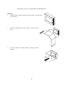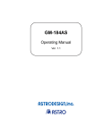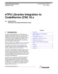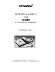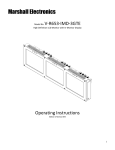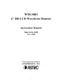
1
WM-3001
6" HD LCD Waveform Monitor
Instruction Manual
March 18, 2002
Ver. 2.00
Video Operations Division
ASTRODESIGN, INC.
1
Contents
Contents.................................................................................................................................................. 1
INTRODUCTION ................................................................................................................................. 3
SAFETY PRECAUTIONS ................................................................................................................... 4
CHAPTER 1 INTRODUCTION TO WM-3001 .............................................................................. 7
1.1
1.2
Outline of WM-3001 ........................................................................................................... 7
Functions of WM-3001 ....................................................................................................... 7
CHAPTER 2 PARTS AND THEIR FUNCTIONS......................................................................... 10
2.1
2.2
WM-3001’s Front View and Components ......................................................................... 10
WM-3001’s Rear View and Components .......................................................................... 11
CHAPTER 3 CONNECTIONS ....................................................................................................... 13
3.1
Connections ....................................................................................................................... 13
CHAPTER 4 OPERATION ............................................................................................................. 14
4.1
4.2
4.3
4.4
Operating the Monitor ....................................................................................................... 14
Performing Mode-by-mode Operations and Using Switches ............................................ 14
4.2.1 Switches Common to All Modes (Fixed-function Switches) ......................15
4.2.2 Picture Mode ...............................................................................................17
4.2.3 Waveform Mode..........................................................................................18
4.2.4 Vectorscope Mode .......................................................................................23
4.2.5 Status Mode.................................................................................................25
4.2.6 Menu Mode .................................................................................................27
Schematic Hierarchy of Switches...................................................................................... 30
Installing and Anchoring the Monitor ............................................................................... 32
CHAPTER 5 MAIN SPECIFICATIONS ....................................................................................... 33
5.1
5.2
5.3
5.4
5.5
5.6
Input Formats..................................................................................................................... 33
Methods of Signal Input .................................................................................................... 35
Methods of Display ........................................................................................................... 35
General Specifications....................................................................................................... 35
Initial Settings.................................................................................................................... 36
Dimensional Drawings ...................................................................................................... 39
CHAPTER 6 STANDARD AND OPTIONAL ACCESSORIES................................................... 40
6.1
Standard Accessories ......................................................................................................... 40
6.2
Optional Accessories ......................................................................................................... 40
Attaching the LCD Protection Panel Supplied as a Standard WM-3001 Accessory ......................... 41
Data Sheet of DM-3000A-03 AC/DC Adapter.................................................................................. 42
Instructions on the Use of DM-3000A-04 Single Rack Mounting Brackets ..................................... 43
Instructions on the Use of DM-3000A-05 Double Rack Mounting Brackets ................................... 44
Instructions on the Use of DM-3000A-08 Shading Hood ................................................................. 45
2
INTRODUCTION
Thank you very much for purchasing Model WM-3001 HD LCD Waveform
Monitor. This manual contains details on the operation procedures to be followed
when the WM-3001 is used, the checkpoints and precautions to be observed, and
other information.
Improper handling may result in malfunctioning. Therefore, before using the
WM-3001, please read through these instructions to gain an understanding on how
to operate the waveform monitor correctly. After reading through the manual,
keep it in a safe place for future reference.
3
SAFETY PRECAUTIONS
WARNING
CONCERNING THE POWER CORD
Always take hold of the molded part of the plug when disconnecting the power cord.
Do not excessively bend or tightly coil the power cord, as this may damage the cord and
eventually cause a fire.
Do not place heavy objects on top of the power cord, as this may damage the cord and eventually
cause a fire or electrical shock.
CONCERNING FOREIGN MATTER
Do not spill liquids, or drop flammable substances or metal parts into the monitor, as this may
cause a fire, electric shocks, or malfunctioning.
DO NOT DISASSEMBLE THE MONITOR!
The monitor contains high-voltage parts. Touching these parts is extremely dangerous and may
result in electric shocks or burns.
CAUTION
CONCERNING THE POWER SUPPLY
Use a supply voltage within the range of 10 V to 18 V.
Do not turn the power back on immediately after having turned it off. Doing so can cause
malfunctioning.
CONCERNING INSTALLATION
Ensure that the following conditions for the installation location are satisfied in order to ensure
that the monitor will be used properly.
1)
Avoid locations where strong magnetic fields and/or vibration is generated, very dusty
locations or locations exposed to water or chemicals.
2)
Avoid locations exposed to direct sunlight and locations susceptible to extreme changes in
humidity or air temperature.
3)
Connect the monitor's power plug to a power outlet separate from the one used for equipment
with a high power consumption such as a copier or one for equipment that generates noise.
4)
Do not place heavy objects such as a CRT monitor directly on top of this unit.
5)
Avoid placing anything directly up against the monitor's rear panel. Doing so will block the
ventilation holes in the rear panel so that the monitor may not operate properly even when its
temperature is within the acceptable ambient range.
4
CONCERNING IMPACT
This is a precision instrument and, as such, subjecting it to impact may cause malfunctioning. Take
special care when moving the monitor.
CONCERNING THE LIQUID CRYSTAL DISPLAY PANEL
The LCD panel is a high-precision part and, as such, the following care must be taken in its
handling.
1)
Wiping the panel's surface with benzine, paint thinners, etc. will cause deterioration in its
quality.
2)
If water (salty water) is left on the display surface, discoloration and staining will result.
3)
Exposing the panel directly to ultraviolet rays for an extended period may cause the deflection
panel to turn brown, the contrast to drop and other forms of deterioration in the display
quality.
4)
Moisture inside the monitor due to condensation, etc. may cause unevenness in the colors.
5)
Due to the nature of liquid crystal, some picture elements may be missing (bright spots or
dark spots).
6)
Directly tapping the surface or bumping it into objects will cause cracking, etc.
7)
Do not attempt to disassemble the panel, as leaking liquid crystal may be harmful if it comes
into contact with your skin.
8)
If you are exposed to liquid crystal because tube surface has broken, rinse it off well with
soap and water.
CONCERNING THE OPERATION LOCATION
If the monitor is used indoors, no special care need be taken. However, installation in the
following locations can cause malfunctioning.
1)
Locations with an ambient temperature outside the range of 5 to 40°C
2)
Locations with an ambient humidity outside the range of 30 to 80% RH
3)
Locations near an air conditioner or subject to rapid temperature changes or the formation of
condensation
4)
Locations exposed to direct sunlight (*1)
5)
Locations exposed to corrosive gases or high concentrations of dust
6)
Locations where strong magnetic fields are generated
7)
Locations which may be splashed with water, oil, chemicals, etc.
8)
Very dusty locations or locations to which vibrations are transmitted from the floor
9)
Unstable locations
*1: Since the panel's backlight may be damaged when the surface temperature of the LCD panel exceeds
60°C, keep the panel away from direct sunlight.
5
WHEN TROUBLE OR MALFUNCTIONING OCCURS
In the unlikely event that trouble or malfunctioning should occur, contact your dealer or an
Astrodesign sales representative.
If trouble occurs in the LCD panel, the user will be charged for repairs and parts replacement even
within one year after delivery.
CONCERNING THIS MANUAL
It is strictly forbidden to copy this manual either in part or in its entirety without permission from
Astrodesign.
1)
The contents and specifications of this manual are subject to change without notice for the
purposes of improving quality.
2)
Although this manual has been prepared with painstaking care, the user is asked to contact
Astrodesign if any ambiguities, mistakes, omissions or other shortcomings are noticed.
3)
The shortcomings in 2) notwithstanding, Astrodesign will not be liable in any way for their
effects on the results achieved by operating the monitor.
6
CHAPTER 1 INTRODUCTION TO WM-3001
1.1 Outline of WM-3001
The WM-3001 is an HDTV waveform monitor which is compact, lightweight, and portable and
which is designed to monitor the pictures being shot during live broadcasts, on location or in
studios, etc.
The monitor can also be powered by the camera battery pack, so pictures can be viewed
absolutely anywhere.
The monitor comes with a number of modes: the picture mode in which the input video is
displayed in color, the waveform mode which displays it as waveforms, the vectorscope mode
that displays it as vectors, and the status mode in which the data is dumped.
A low-temperature polysilicon thin-film transistor (TFT) LCD panel is used for the monitor's
display.
The input signals support 20 different video formats in all, including 19 HDTV formats and one
SDTV format. HDTV SDI and SDTV SDI digital signals and HDTV analog signals can easily be
selected. An HDTV SDI signal refers to a 1.485 Gbps NRZ serial digital signal, while an SDTV
SDI signal refers to a 270 Mbps NRZ serial digital signal. The formats supported for HDTV are
1080/60i, 1035/60i, 720/60p, 720/24p, 1080/24p, 1080/24sF, 1080/30p, 1080/30sF, 1080/25p,
1080/25sF and 1080/50i. For SDTV, the WM-3001 supports the 525/60i format with frequency
rates of 1.000 and 1/1.001. The field frequencies (60/59.94 Hz, 24/23.98 Hz, etc.) of each format
are automatically supported.
Six-inch low-temperature polysilicon TFT LCD panel
Lightweight and compact size (3U half-size)
12 V DC power supply (10 to 18 V)
Operable on camera battery
Supported standards of HDTV SDI input: SMPTE 292M, BTAS-004B, and BTAS-006B
(1.485 Gbps SDI input)
Supported standards of HDTV SDI audio input: SMPTE 299M
Supported standards of SDTV SDI input: SMPTE 259M (270 Mbps SDI input)
Supported standards of HDTV analog input and its format: SMPTE 274M, SMPTE 296M,
and BTAS-001B
1.2 Functions of WM-3001
Compatible with HDTV SDI and SDTV SDI digital input and HDTV analog input
(Y/Pb/Pr) signals
♦ HDTV SDI input: Signals compatible with SMPTE 292M, etc. are input to and viewed
on the monitor (with MONITOR OUT terminal).
• No-signal/CRCC error count readings (0 to 999999999, or ********* for higher
counts)
• Readings of time for last CRCC error detection (LAST) (up to 99 hours 59 minutes 59
seconds, or * for longer times)
7
♦ SDTV SDI input: Signals compatible with SMPTE 259M, etc. are input to and viewed on
the monitor (with MONITOR OUT terminal).
♦ HDTV analog input: YPbPr signals (Y_On Sync) compatible with BTAS-001B are input
to and viewed on the monitor.
Supports 20 different video formats
(HDTV: 1080/60i, 1080/24p, 1080/24sF, 1080/30p, 1080/30sF, 1080/25p, 1080/25sF
1080/50i, 1035/60i, 720/60p, and 720/24p; SDTV: 525/50i)
Automatically supports the field frequency rates of 60 Hz, 60/1.001 Hz, etc.
Displays the format and field frequency rate of an input signal and the format selected for
output.
Displays the time elapsed from reset (TIME) (up to 99 hours 59 minutes 59 seconds, or *
for longer times)
The POWER LED comes on when the power is turned on.
The ERROR LED comes on if an error occurs in the input signal or when no input signal is
supplied.
Outputs a BLACK signal when input signals are absent.
Supports two-channel tally signal input (driven by external contacts; the red or green LED
lamp above the screen comes on upon input of a TALLY signal).
Overlay function (superimposes an input picture on top of another)
Freeze/update function
Allows for selection from of a choice of five modes: menu mode, picture mode, waveform
mode, vectorscope mode, and status mode.
Picture mode: Displays input pictures in color
• Displays markers (center marker, and frame marker with safety marker; aspect ratios of
4:3, 13:9, 14:9 and 2.4:1)
• Video adjustments using brightness, contrast, Pb (Cb), Pr (Cr), and chroma controls
• Turns on/off CHROMA option.
Waveform mode: Displays the waveforms of input pictures.
• Overlay display (overlays the waveforms of Y/Pb (Cb)/Pr (Cr) or G/B/R signals on top
of each other)
• Parade display (places the waveforms of Y/Pb (Cb)/Pr (Cr) or G/B/R signals next to
one another) (for 1H- and 1F-sweep displays only)
• 1H/2H/1F/2F-sweep displays (2H/2F-sweep displays are for the interlace format only)
• Line select function for displaying desired lines (for 1H/2H-sweep displays only)
• Shows markers in mV or % increments
• GAIN (×1, ×2, or ×4); MAG (×1, ×2, or ×4) (for 1H-sweep overlay display only)
• Measures amplitude or time differences between waveforms using cursor (time
differences are only available for 1H/2H-sweep displays)
• Converts Y/Pb/Pr (YCbCr) to G/B/R for display as GBR pictures
Vectorscope mode: Displays input pictures in vectorscope images
•
•
•
•
Magnifies black and white levels (×1, ×2, or ×4)
100% and 75% color bars for markers
Choice of two scales: XY and IQ axes
Line select function for displaying desired lines
8
Status mode: Sequentially displays digital values obtained from arbitrarily sampled lines
of input pictures.
• Allows for single-action movement to EAV/SAV position.
• Can display not only video data but also auxiliary data for sampled lines.
• Indicates audio levels in a bar graph (only when HDTV SDI signals are input).
Menu mode
•
•
•
•
•
•
•
•
•
•
Sets the mode of input signals (SDI or ANALOG).
Sets the format.
Sets the values of BRIGHT, CONTRAST, Pb (Cb), Pr (Cr) and CHROMA options.
Selects from the CHROMA ON/OFF options.
Sets the value of CONTRAST for the overlay mode display of input video
(NORMAL/DIM).
Sets the waveform display (YP (YC) or GBR).
Sets the scale of the waveform display (% or V).
Selects a marker for vectorscope mode display (100% or 75%).
Resets the error count.
Calls up the saved settings, saves settings, and initializes the settings.
9
CHAPTER 2 PARTS AND THEIR FUNCTIONS
2.1 WM-3001’s Front View and Components
WM-3001’s Front View
1
TALLY
2
HD WAVEFORM MONITOR
WM-3001
ERROR
POWER
MODE
F1
FREEZE
F2
LINE SEL
F3
OVERLAY
F4
FUNCTI ON
F5
POWER
Front-panel Components and Their Functions
Number
Component
Liquid crystal display
TALLY 1
TALLY 2
ERROR LED
POWER LED
MODE (*2)
FREEZE (*2)
LINE SEL (*2)
OVERLAY (*2)
FUNCTION (*2)
F1 (*3)
F2 (*3)
F3 (*3)
F4 (*3)
F5 (*3)
Description of Function
Displays pictures.
TALLY lamp (red): controlled by rear-panel tally connector (contact-driven).
TALLY lamp (green): controlled by rear-panel tally connector (contact-driven).
ERROR lamp (red): comes on when there are no input signals or when an error occurs.
POWER lamp (green): comes on when the power is supplied.
Shows a menu of modes to select from.
Switches between the FREEZE and
*2: These switches have fixed functions. For
UPDATE options.
further details, see "Common to all modes
Shows a menu of lines to select from.
(fixed function switches)" in subsection
Sets the picture overlay function to ON or
4.2.1.
OFF.
Shows a menu of functions to select from.
FUNCTION 1
*3: These switches provide different functions
FUNCTION 2
depending on the mode. For further
details, see the operation method of each
FUNCTION 3
mode described in subsections 4.2.2 to
FUNCTION 4
4.2.6.
FUNCTION 5
10
POWER
3/8" threaded hole
Switches between the power-on and stand-by states.
Screw hole for anchoring the monitor onto a tripod, arm, etc.
2.2 WM-3001’s Rear View and Components
WM-3001’s Rear View
I NPUT
IN
MONI TOR OUT
SDI
MODEL:
SER NO: XXXXXXXXX
MADE I N JAPAN
Y
PB
ANA.
YPBPR
HDTV
ANALOG
PR
TALLY
POWER
DC I N( 12V)
75ƒ
¶
Y
PB
PR
DI GI .
HI GH
Rear-panel Components and Their Functions
Number
Component
Description of Function
SDI IN
Input terminal for HDTV SDI and SDTV SDI signals
SDI MONITOR OUT
Output terminal for simplified monitoring of input signals
ANALOG Y
Input terminal for the Y signal of HDTV analog input. For HDTV analog input,
synchronization is achieved by means of the Y signal.
ANALOG Pb
Input terminal for the Pb signal of HDTV analog input
ANALOG Pr
Input terminal for the Pr signal of HDTV analog input
POWER
Turns on/off the power.
Power supply connector
Four-pin, round male camera connector for 12 V input (GND: pin 1; 12 V: pin 4).
TALLY connector (*4)
Four-pin, round female camera connector (TALLY 1 (red): pins 1 and 4; TALLY 2
(green): pins 2 and 3).
Termination selector switch
Switches between the terminating resistors of YPbPr signal input.
*4 Power supply and TALLY connectors
11
DC IN (12 V)
GND (pin 1)
N.C.
(pin 2)
IN(12V)
Silk-screen printed on chassis
DC12V (pin 4)
GND (pin 1)
N.C. (pin 3)
GND (pin 3)
TALLY
TALLY_R (pin 1)
Y
TALLY_G (pin 2)
4-pin round male camera connector
4-pin round female camera connector
• The pin assignments of the power supply and tally connectors are as shown in the figure above
(power supply connector on the left and tally connector on the right). Be careful, as the two
connectors have different pin assignments even though they look identical.
• To turn on the TALLY 1 (red) lamp, short-circuit the pins marked
• To turn on the TALLY 2 (green) lamp, short-circuit the pins marked
12
.
.
CHAPTER 3 CONNECTIONS
3.1 Connections
This section describes how to wire the WM-3001.
(1) Connecting the power supply
Connect the power supply to the round camera connector serving as a power supply
connector ( in the rear view). This connector has 4 pins: pin 1 (GND), pin 4 (DC input)
and pins 2 and 3 (no connection). Either the accessory cable (4-pin round camera
connector/cannon connector conversion cable) or the optional (*) DC input cable
(DM-3000A-09) is available for the power supply connector. Check the configuration of
your cable end connector prior to use.
(2) Connecting the source of input signals
When inputting HDTV SDI or SDTV SDI signals, connect the signal source to the SDI
terminal using a BNC coaxial cable. The IN terminal is used to input SDI signals, and the
MONITOR OUT terminal is used to monitor the SDI signals being input. Supply
BTAS-004B or SMPTE 259M compatible serial digital signals to the SDI input terminal.
For SDI signals, use a coaxial cable (5C-FB or equivalent) capable of handling the 1.5 GHz
band.
When inputting HDTV analog signals, connect the sources of Y, Pb and Pr signals to the
ANALOG Y, ANALOG Pb and ANALOG Pr terminals, respectively. Supply BTAS-001B
compatible Y/Pb/Pr signals to the ANALOG input terminal. Synchronization is achieved by
means of the Y signal.
(3) Setting
Use the menu mode to set up input signals and their formats. Also make other settings as
necessary. Do not change the settings of the rear-panel DIP switch unless you need to
change the terminating resistor.
* For details on optional accessories see Chapter 6, Section 6.2, “Optional Accessories.”
13
CHAPTER 4 OPERATION
4.1 Operating the Monitor
First check that the WM-3001 is wired and set up correctly. Then, turn on the rear-panel POWER
switch of the WM-3001. The POWER lamp comes on, and the monitor displays the input
picture.
If the green POWER lamp fails to come on, check that the front-panel POWER switch is turned
on. If the green POWER lamp still remains off, check the connections once again.
If the screen looks distorted or runs out of synchronization, check the FORMAT settings.
For simple monitoring of the SDI input signals, monitor them at the MONITOR OUT terminal.
The analog input signals will not provide any picture unless the Y signal contains a
synchronization signal. For details on the signal level and other specifications, refer to
BTAS-001 or other standards.
When there are no input signals, the ERROR LED lamp comes on, and the text BLACK is
displayed.
If an HDTV SDI signal is being input, the ERROR LED lamp also comes on even in the case of
CRC error.
If the screen displays “NO SIGNAL” even if an input signal is applied, check the settings of the
menu mode.
Note that data values presented for analog input are for reference purposes only and should be
used as rule-of-thumb values.
4.2 Performing Mode-by-mode Operations and Using Switches
The WM-3001 has five modes: the menu mode, picture mode, waveform mode, vectorscope
mode and status mode.
There are two types of switches: switches with functions that do not vary with mode, and
switches whose functions vary mode by mode. For details on operations, refer to the description
of each mode on the following pages.
4.2.1
4.2.2
4.2.3
4.2.4
4.2.5
4.2.6
Switches Common to All Modes (Fixed-function Switches) ......................15
Picture Mode ...............................................................................................17
Waveform Mode..........................................................................................18
Vectorscope Mode .......................................................................................23
Status Mode.................................................................................................25
Menu Mode .................................................................................................27
14
4.2.1
Switches Common to All Modes (Fixed-function Switches)
• The functions of the following switches are common to all modes.
• Note that some switches are not available depending on the mode.
Switch Name
MODE
FREEZE
LINE SEL
OVERLAY
FUNCTION
Number Marked in
Front View
Description of Function
Turns on/off the menu of modes to select from.
Switches between the FREEZE and UPDATE options of input pictures.
Turns on/off the menu of lines to select from.
Turns on/off the picture overlay function.
Turns on/off the menu of functions to select from.
MODE: Shows a menu of modes to select from.
The texts PICTURE, WAVEFORM, VECTOR, STATUS and MENU appear on the
screen next to the F1, F2, F3, F4 and F5 switches, respectively. Pressing the F1 to F5
switches in this order with these texts on screen moves through the picture mode,
waveform mode, vectorscope mode, status mode, and menu mode. This switch can be
used in any of the operation modes.
FREEZE: Switches between the FREEZE and UPDATE options of input pictures.
The text FREEZE is shown in reverse video at the top of the LCD display as long as the
input picture is kept frozen. Input video data at that point is retained. This switch can be
used in any of the operation modes.
Note: Do not change the input video format or input channel during freeze, as this may cause the
monitor to malfunction.
LINE SEL: Enables you to select a line to monitor.
This switch can only be used in the waveform and vectorscope modes. The numbers of
the selected line and field appear in the upper-right corner of the screen.
For HDTV signal input, the numbers read as shown below:
∗:
←Field number (where, ∗ denotes 1 or 2)
0423
←Line number
(0986)
←Total sum of lines (visible only when F2 is shown)
For SDTV signal input, the numbers read as shown below:
∗:
0251
(0254)
←Field number (where, ∗ denotes 1 or 2)
←Field line number
←Total sum of lines
If you turn on the picture overlay function when the LINE SEL switch is on, the position of the
selected line is indicated on the overlay picture.
OVERLAY: Outputs the input picture onto the background. This switch cannot be used in the
picture mode.
If you set the OVERLAY CONT option of the menu mode to NORMAL (default), a pre-adjusted
input picture is output onto the background.
If you set the OVERLAY CONT option of the menu mode to DIM, the overlay picture of a mode
15
other than the menu mode is output onto the background at a 25% contrast level.
FUNCTION: Changes the functions of the F1 to F5 switches when the monitor is in the waveform
mode.
When HDTV SDI signal input is selected, the FUNCTION switch switches between data
dumping and audio monitoring in the status mode. This switch cannot be used in any other mode.
16
4.2.2
Picture Mode
• This mode displays input pictures in color.
• In this mode, you can only work with the on-screen markers (center marker, and frame marker
with an aspect ratio of 4:3, 13:9, 14:9, or 2.4:1).
• The name of a selected marker is shown in reverse video.
• Use the menu mode to adjust pictures using the brightness, contrast, Pb (Cb), Pr (Cr), and
chroma controls or show/hide the chroma control.
Switch
Name
F1
F2
F3
F4
F5
Number Marked in
Front View
F1:
(CENTER)
F2:
(FRAME)
F3:
(4:3/13:9/14:9)
F4:
(2.4:1)
F5:
(FUNCTION DISPLAY)
Description of Function
Turns on/off the center marker.
Turns on/off the frame marker (16:9) and safety marker (16:9 [90%]).
Selects from the 4:3/13:9/14:9 markers.
Turns on/off the 2.4:1 marker.
Turns on/off the menu of functions.
Shows the cross marker in the middle of the picture view area.
Shows the frame marker (solid outline) and safety marker (dotted outline)
in the picture view area. The frame marker has an aspect ratio of 16:9, and
the safety marker is shown inside the frame marker at 90% the size
thereof.
Selects from the 4:3/13:9/14:9 markers (vertical lines). Each press of this
switch cycles through the 4:3, 13:9, and 14:9 markers.
Shows the 2.4:1 marker (horizontal line).
Shows the menu of the functions (cursor names) of the F1 to F4 switches.
Note: Care must be taken since when the 1035 format is used, each of the center marker, the frame
marker, and the 4:3, 13:9, 14:9, and 2.4:1 markers takes a 1080 format value.
17
4.2.3
Waveform Mode
•
By default, this mode displays a 1H-sweep waveform of input video. You can select from the
1H, 2H, 1F, and 2F sweep options for the waveform to be displayed. Note that you can select
the 2H and 2F-sweep displays only when the input video is in the interlace format or
segment frame format.)
•
You can select a Y/Pb/Pr (YCbCr) or G/B/R signal to display its waveforms. Use the menu
mode to switch between the waveforms to be displayed.
•
The overlay display function of the waveform mode overlays the Y/Pb/Pr or G/B/R
waveforms.
•
The parade display function of the waveform mode places the Y/Pb/Pr or G/B/R waveforms
next to one another. This function presents only a 1H (1F)-sweep display even when you
have selected the 2H (2F)-sweep display.
•
If you change a parade display to an overlay display, the waveform mode provides only a 1H
(1F)-sweep display. The mode does not retain the 2H (2F)-sweep display settings.
•
The V GAIN and H MAG magnification functions are available. You can choose from ×1
(default), ×2, and ×4 options.
•
Use the H MAG magnification function for a 1H-sweep overlay display only.
•
The line select function (LINE SEL switch) is available.
When this function is used, the monitor provides a 1H-sweep display (or 2H-sweep display,
if this display has been selected).
•
When an HDTV signal is being input, turning off the line select function results in the
sampling of lines through a decimation process.
•
When an SDTV signal is being input, turning off the line select function results in the
sampling of all lines.
•
You can use the settings of selected lines also in other modes since the settings are retained.
•
The picture overlay function (OVERLAY switch) is available.
When the line select function is in use, the position of a selected line is shown on the overlay
picture.
Switch Name
Number Marked in
Front View
FUNCTION
FUNCTION:
Description of Function
Switch for driving the menu of functions.
Pressing the FUNCTION switch and then one of the F1 to F5 switches
selects the function of that switch.
F1: DISPLAY, F2: SWEEP, F3: CURSOR, F4: GAIN/MAG, F5: SCROLL
(shown only for the GAIN/MAG magnification function)
Switch for driving the menu of functions.
The texts DISPLAY, SWEEP, CURSOR, GAIN/MAG and SCROLL (shown only for the
GAIN/MAG magnification function) appear on the screen next to the F1, F2, F3, F4, and F5
switches, respectively. Pressing one of the F1 to F5 switches when these texts are on screen
shows the menu for adjusting the function of that switch.
18
Functions Available when F1 (DISPLAY) Is Pressed
Switch Number Marked in
Name
Front View
F1
F2
F3
F4
F5
F1:
(PARADE)
F2:
(OVERLAY)
F3:
(Y/G)
F4:
(Pb(Cb)/B)
F5:
(Pr(Cr)/R)
Description of Function
Parade display
Overlay display
Turns on/off channel 1 (Y/G).
Turns on/off channel 2 (Pb/B).
Turns on/off channel 3 (Pr/R).
Presents a 1H/1F-sweep display of Y/Pb/Pr or G/B/R waveforms by placing them
next to one another.
Shows Y/Pb/Pr or G/B/R waveforms by overlaying them on top of each other.
Shows the waveform of channel 1 (Y/G).
Pressing this switch with the parade display selected shows only the Y/G
waveforms of the overlay display.
Shows the waveform of channel 2 (Pb(Cb)/B).
Pressing this switch with the parade display selected shows only the Pb(Cb)/B
waveforms of the overlay display.
Shows the waveform of channel 3 (Pr(Cr)/R).
Pressing this switch with the parade display selected shows only the Pr(Cr)/R
waveforms of the overlay display.
Functions Available when F2 (SWEEP) Is Pressed
Switch
Name
F1
F2
F3
F4
F5
F1:
(1H)
F2:
(2H)
F3:
(1F)
F4:
(2F)
Number Marked in
Front View
Description of Function
Presents a 1H-sweep display of waveforms on the screen.
Presents a 2H-sweep display of waveforms on the screen.
Presents a 1F-sweep display of waveforms on the screen.
Presents a 2F-sweep display of waveforms on the screen.
Presents a 1H-sweep display of waveforms on the screen.
Presents a 2H-sweep display of waveforms on the screen.
This option is selectable only when the input signal is in the interlace format or
segment frame format, and not shown in the menu in the case of the progressive
format.
Presents a 1F-sweep display of waveforms on the screen.
This option is selectable only when all lines are sampled, and not shown in the
menu when the LINE SEL switch is set to ON.
Presents a 2F-sweep display of waveforms on the screen.
This option is selectable only when the input signal is in the interlace format or
segment frame format and all lines are sampled; the option is not shown in the
menu in the case of the progressive format, or the LINE SEL switch is set to ON.
19
Functions Available when F3 (CURSOR) Is Pressed
Switch
Name
F1
F2
F3
F4
F5
Number Marked in
Front View
Description of Function
Increments the BASE, OFFSET or TRACK option.
Decrements the BASE, OFFSET or TRACK option.
Switches between the BASE, OFFSET and TRACK options.
Switches between the cursors.
F1:
(INC)
F2:
(DEC)
F3:
(BASE/OFFSET/
TRACK)
F4:
(CURSOR
OFF/H/V)
Moves the cursor selected by the F3 switch (for selection from
BASE/OFFSET/TRACK) in the “+” direction.
When TRACK is selected, this option moves both cursors. The interval between
the cursors remains unchanged.
Moves the cursor selected by the F3 switch (for selection from
BASE/OFFSET/TRACK) in the “−” direction.
When TRACK is selected, this option moves both cursors. The interval between
the cursors remains unchanged.
Each press of this switch cycles through the BASE, OFFSET and TRACK
options. The solid-line cursor is displayed for BASE and the dotted-line cursor for
OFFSET. The TRACK option causes both cursors to be selected.
Each press of this switch cycles through the CURSOR OFF, CURSOR H
(horizontal line) and CURSOR V (vertical line) options.
Functions Available when F4 (GAIN/MAG) Is Pressed
Switch
Name
F1
F2
F3
F4
F5
Number Marked in
Front View
F1:
(GAIN ×1/×2/×4)
F2:
(MAG ×1/×2/×4)
Description of Function
Switches between the options of V GAIN.
Switches between the options of H MAG.
Changes the V GAIN (vertical magnification) setting.
You can select from the ×1, ×2, and ×4 options of V GAIN.
Changes the H MAG (horizontal magnification) setting.
You can select from the ×1, ×2, and ×4 options of H MAG. This switch option is
selectable only if a 1H-sweep overlay display is selected, and not shown in the
menu when any other type of display is selected.
20
Functions Available when F5 (SCROLL) Is Pressed
Switch Number Marked in
Name
Front View
F1
F2
F3
F4
F5
Description of Function
Scrolls the magnified waveform upward.
Scrolls the magnified waveform downward.
Scrolls the magnified waveform to the right.
Scrolls the magnified waveform to the left.
Resets the point of scrolling.
F1:
(SCROLL UP)
Scrolls the magnified waveform upward.
This option is effective only when the ×2 or ×4 option of V GAIN is selected, and
not shown in the menu when the ×1 option is selected.
F2:
Scrolls the magnified waveform downward.
(SCROLL
This option is effective only when the ×2 or ×4 option of V GAIN is selected, and
DOWN)
not shown in the menu when the ×1 option is selected.
Scrolls the magnified waveform to the right.
F3:
This option is effective only when the ×2 or ×4 option of H MAG is selected, and
(SCROLL
not shown in the menu when the ×1 option is selected.
RIGHT)
F4:
Scrolls the magnified waveform to the left.
(SCROLL LEFT) This option is effective only when the ×2 or ×4 option of H MAG is selected, and
not shown in the menu when the ×1 option is selected.
F5:
Resets the point of scrolling.
(RESET)
This option reverts the waveform to be displayed to the black-level waveform for
the starting point of an on-screen picture.
Functions Available when LINE SELECT Menu Is Enabled
Switch
Name
F1
F2
F3
F4
F5
Number Marked in
Front View
F1:
(LINE INC)
F2:
(LINE DEC)
F3:
(LINE SEL OFF/ON)
F4:
(FIELD)
Description of Function
Increments the lines.
Decrements the lines.
Turns on/off the line select function.
Switches between the fields.
Increments the number of lines to be selected.
You can specify the number and show waveforms on a 1H-sweep basis. If
you select a 2H-sweep display, the monitor presents a 2H-sweep display of
waveforms. This option is not shown in the menu when LINE SEL is set to
OFF.
Decrements the number of lines to be selected.
You can specify the number and show waveforms on a 1H-sweep basis. If
you select a 2H-sweep display, the monitor presents a 2H-sweep display of
waveforms. This option is not shown in the menu when LINE SEL is set to
OFF.
Turns on/off the line select function.
Switches between the fields.
This option is effective only when the input signal is in the interlace format
21
or segment frame format. This option is not shown in the menu in the case
of the progressive format.
22
4.2.4
Vectorscope Mode
•
This mode provides the vectorscope displays of input pictures.
•
You can magnify the black and white levels (×1, ×2, or ×4).
•
You can select from the 100% and 75% color bars for the markers. (Use the menu mode to
select from the markers.)
•
In addition to the regular XY axes, IQ axes are displayed for the scale.
•
The line select function (LINE SEL switch) is available.
When this function is used, the screen presents a 1H-sweep display (or 2H-sweep display, if
this display mode has been selected).
•
When an HDTV signal is being input, turning off the line select function results in the
sampling of lines through a decimation process.
•
When an SDTV signal is being input, turning off the line select function results in the
sampling of all lines.
•
You can use the settings of selected lines also in other modes since the settings are retained.
•
The picture overlay function (OVERLAY switch) is available.
When the line select function is in use, the position of a selected line is shown on the overlay
picture.
Switch
Name
F1
F2
F3
F4
F5
Number Marked in
Front View
F1:
(LINE INC)
F2:
(LINE DEC)
F3:
(LINE SEL OFF/ON)
F4:
(FIELD)
F5:
(GAIN ×1/×2/×4)
Description of Function
Increments the lines.
Decrements the lines.
Turns on/off the line select function.
Switches between the fields.
Selects from the options of black- and white-level magnification.
Increments the number of lines to be selected.
You can specify the number and show waveforms on a 1H-sweep basis. If
you select a 2H-sweep display, the monitor presents a 2H-sweep display of
waveforms. This option is not shown in the menu when LINE SEL is set to
OFF.
Decrements the number of lines to be selected.
You can specify the number and show waveforms on a 1H-sweep basis. If
you select a 2H-sweep display, the monitor presents a 2H-sweep display of
waveforms. This option is not shown in the menu when LINE SEL is set to
OFF.
Turns on/off the line select function. This option appears when the LINE
SELECT menu is enabled (LINE SEL switch is pressed).
Switches between the fields.
This option is effective only when the input signal is in the interlace format
or segment frame format. This option is not shown in the menu in the case
of the progressive format.
Selects from the options of a channel’s black- and white-level magnification.
You can select from the ×1, ×2 and ×4 options of GAIN.
23
Note: The F1 to F4 options are shown only when the line select menu is enabled (LINE SEL switch is
pressed).
24
4.2.5
Status Mode
•
This mode shows the statuses (values) or audio data (bar graph).
•
This mode indicates the EAV/SAV positions at the time of data dumping.
•
You can also use the settings of lines selected for data dumping in other modes since the
settings are retained.
•
You can monitor audio data when the HDTV SDI format is selected.
•
You can monitor the audio data on as many as 16 channels.
•
In principle, the audio level is for reference purposes only and should be used.
•
The unit dB of an audio level is represented as the ratio dBFS of the 24-bit full scale.
•
The picture overlay function (OVERLAY switch) is available.
•
At the time of data dumping, information on the selected position is indicated on the overlay
picture.
Switch Name
Number Marked in
Front View
Switch for selecting from functions.
This switch selects from the “data dumping” and “audio monitoring”
options.
FUNCTION
FUNCTION:
Description of Function
Switch for selecting from functions.
When the HDTV SDI format is selected, this switch switches between data
dumping and audio monitoring. When the HDTV analog format or SDTV format
is selected, you cannot switch to audio monitoring.
Functions Available when Data Dumping Is Selected
Switch
Number Marked in
Description of Function
Name
Front View
F1
Increments the lines or samples.
F2
Decrements the lines or samples.
F3
Switches between the options “selected lines” and “starting sample.”
F4
Switches between the fields.
F5
Jumps to the EAV/SAV position.
F1:
(LINE INC/SMPL INC)
F2:
(LINE DEC/SMPL DEC)
F3:
(LINE/SAMPLE)
F4:
(FIELD)
♦ F5:
Increments the number of lines or samples to be selected.
Decrements the number of lines or samples to be selected.
Switches between the options “selected lines” and “starting sample.”
Turns on/off the line select function.
Switches between the fields.
This option is effective only when the input signal is in the interlace
format or segment frame format. This option is not shown in the menu in
the case of the progressive format.
Jumps to the EAV/SAV position.
25
Screen View when Audio Monitoring Is Selected
CH
1 A
2 A
-53
-38
-30
-20
-10
0
dB
3
4
5 A
6 A
7
8
9
10
11
12
13
14
15
16
Active-channel indicator
Symbol A appears next to channels that are effective for any given
audio control packet.
Level indicator
The level of each channel is indicated with a bar.
Note: The “audio monitoring” option is available only when an HDTV SDI signal is being input.
26
4.2.6
Menu Mode
• In this mode, you can select SDI signal input or analog YPbPr signal input.
• You can select the desired format for these inputs.
For HDTV signal input, select from:
1080/60i, 1035/60i, 720/60p, 720/24p, 1080/24p, 1080/24sF, 1080/30p, 1080/25p, and
1080/25sF;
For SDTV signal input, select 525/60i.
For the 1080/30sF format of HDTV, select 1080/60i and for the 1080/50i format of HDTV,
select 1080/25sF.
• You can set the values of BRIGHT, CONTRAST, Pb(Cr), Pr(Cr), and CHROMA settings.
• You can set the CHROMA option to ON or OFF.
• For the CONTRAST setting of an overlay picture, you can switch between the value of a
pre-adjusted picture and a forcibly reduced value (25%).
• You can switch between the Y/Pb/Pr settings and G/B/R settings for the waveform on
display.
• The scale of waveform displays can be switched between % and V.
• You can switch between the 100% and 75% options for the marker of a vectorscope display.
• You can reset the error count.
• You can call up the saved settings, save settings, and initialize the settings.
Switch
Name
F1
F2
F3
F4
F5
F1:
(UP)
F2:
(DOWN)
F3:
F4:
F5:
Number Marked in
Front View
Description of Function
Moves the menu-selecting cursor up one setup item.
Moves the menu-selecting cursor down one setup item.
Adjusts or changes the selected setup item.
Adjusts or changes the selected setup item.
Executes the selected setup item.
Moves the menu-selecting cursor (> in reversed video) up one setup
item.
If already at the topmost option (CHANNEL), the cursor jumps to the
bottommost option (INIT SETTING).
Moves the menu-selecting cursor (> in reversed video) down one setup
item.
If already at the bottommost option (INIT SETTING), the cursor jumps
to the topmost option (CHANNEL).
Moves the menu-selecting cursor (> in reversed video) one option of the
selected setup item to the left.
When the BRIGHT, CONTRAST, Pb (Cb), Pr (Cr), or CHROMA option
is selected, this switch increments the value of that option.
Moves the menu-selecting cursor (> in reversed video) one option of the
selected setup item to the right.
When the BRIGHT, CONTRAST, Pb (Cb), Pr (Cr), or CHROMA option
is selected, this switch decrements the value of that option.
Executes the selected setup item.
The ERROR RESET, LOAD SETTING, SAVE SETTING, or INIT
SETTING setup item is executed.
27
CHANNEL: Select SDI or ANALOG according to the format of input signals. Note that if you
select ANALOG when the format is 525/60i, the 1080/60i format is applied.
FORMAT: Select the format that matches the format of input pictures. Note that if you have
selected ANALOG, you cannot select the 525/60i format. For details on the formats see
Chapter 5, “Main Specifications.”
BRIGHT: You can set the brightness level (variable from -6.8% to +6.7%).
Display level
100
Brightness signal level
+6.7%
0%
-6.8%
0
100
Input level
CONTRAST: You can set a difference between brightness and darkness levels. (variable from 50%
to 150%).
Display level
100
Brightness signal level
150
100
50
0
Input level
100
Pb (Cb), Pr (Cr), and CHROMA: You can set the level of color-difference signals (variable from
50% to 150%). For the Pb (Cr), and Pr (Cr) options, set the Pb (Cr) and Pr (Cr) levels
separately. For the CHROMA option, set the Pb (Cr), and Pr (Cr) levels at the same
time.
Display level
100
Color difference signal level
150
100
50%
Input level
100
Note: If you separately set either the Pb (Cb) or Pr (Cr) level for the Pb (Cb) or Pr (Cr) option, and
then set the CHROMA option, the individual Pb (Cb) and Pr (Cr) settings are cancelled. The
28
latest settings of these options are also cancelled if you attempt to readjust the settings after
turning off the power. To keep the Pb (Cb) and Pr (Cr) levels in memory for a prolonged period,
save the individual Pb (Cb) and Pr (Cr) settings when you set them up separately.
CHROMA ON/OFF: This option turns on or off the CHROMA setup item.
OVERLAY CONT: This option outputs an overlay picture in modes other than the menu mode at
the valued of a pre-adjusted picture (NORMAL) of the CONTRAST setup item. You
can also output the picture with the value of CONTRAST always decreased to 25%
(DIM).
WAVEFORM: You can switch between the Y/Pb/Pr (YCbCr) settings and G/B/R settings for the
waveform on display. Note however that YPbPr (YCbCr) is represented as YP (CP).
SCALE: Switches the scale of waveform displays between % and V.
COLOR BAR: Switches between the 100% and 75% options for the marker of a vectorscope
display.
ERROR RESET: Resets the error count.
LOAD SETTING: Calls up the saved settings.
SAVE SETTING: Saves settings.
During saving, the text "WORKING" appears in reverse video. Do not turn off the power
before this indication goes out.
Note: Once the power is turned off, the settings of the monitor are those that were saved last. (If no
settings have been saved, the monitor reverts to the default settings.) It is advisable to save the
latest settings before you turn off the power.
INIT SETTING: Initializes the settings.
29
4.3 Schematic Hierarchy of Switches
When MODE Switch Is Pressed
PICTURE
MARKER CENTER
FRAME
4:3 / 13:9 / 14:9
2.4:1
FUNCTION DISPLAY
WAVEFORM
PARADE
OVERLAY
Y
Note: Another menu opens when you press the FUNCTION switch.
See the separate table (page 21) for further details.
Pb(Cb)
Pr(Cr)
VECTOR
GAIN ×1/×2/×4
STATUS
LINE INC/SMPL INC
LINE INC/SMPL DEC
LINE/SAMPLE
FIELD
Note: Pressing the FUNCTION switch changes to audio
monitoring (for HDTV SDI format only).
EAV/SAV
MENU
UP
DOWN
SDI/PREV/INC/ON/NORMAL/YP(YC)/%/100%
ANALOG/NEXT/DEC/OFF/DIM/GBR/V/75%
RESET/LOAD/SAVE/INIT
When LINE SEL Switch Is Pressed
LINE INC *
LINE DEC *
LINE SEL OFF
ON
FIELD *
* Shown when LINE SEL is set to ON.
30
Note: These items vary depending
on the option selected.
When FUNCTION Switch Is Pressed in Waveform Mode
DISPLAY
PARADE
OVERLAY
Y
Pb (Cb)
Pr (Cr)
SWEEP
1H
2H
1F *
2F
CURSOR
Not shown when a progressive signal is being input.
* Not shown when LINE SEL is set to ON.
*
OFF
ON
H
INC
DEC
BASE
OFFSET
TRACK
V
INC
DEC
BASE
OFFSET
TRACK
GAIN/MAG
GAIN ×1/×2/×4
MAG ×1/×2/×4
SCROLL
SCROLL UP
SCROLL DOWN
Note: Not shown when GAIN or MAG is set to ×1.
SCROLL RIGHT
SCROLL LEFT
Not shown when GAIN is set to ×1.
RESET
Not shown when MAG is set to ×1.
31
4.4 Installing and Anchoring the Monitor
This monitor has holes for 3/8" screws on both its top and bottom. Use them to secure the
monitor to a camera tripod or arm, etc. To mount the monitor in a rack, use the optional*
brackets.
* For further details on the optional accessories, see Chapter 6, Section 6.2, “Optional
Accessories.”
32
CHAPTER 5 MAIN SPECIFICATIONS
5.1 Input Formats
You can set the following input formats in the menu mode. The monitor automatically recognizes
the frame rate (e.g., 60/59.94 or 24/23.98).
Frame
Rate
[Hz]
Format
1035/60i
1035/59.94i
1035/60i
1080/59.94i
1080/29.97sF
Active
Line
per
Frame
Total
Line
per
Frame
Samples
per
Active
Line
Samples
per
Total
Line
Line
Frequency
[kHz]
30/1.001
30
1035
1035
1125
1125
1920
1920
2200
2200
33.72
33.75
30/1.001
1080
1125
1920
2200
33.72
1080/30sF
1080/30p
1080/29.97p
1080/30p
Interlace
Interlace
Interlace
Segmented
Frame
1080/60i
1080/60i
Scanning
Interlace
30
1080
1125
1920
2200
33.75
Segmented
Frame
30/1.001
30
1080
1080
1125
1125
1920
1920
2200
2200
33.72
33.75
Progressive
Progressive
Segmented
1080/25sF
(1080/50i)
1080/25sF
1080/25p
1080/25p
25
1080
1125
1920
2640
28.13
1080/23.98sF
24/1.001
1080
1125
1920
2750
26.97
1080/24sF
24
1080
1125
1920
2750
27.00
1080/23.98p
24/1.001
24
1080
1080
1125
1125
1920
1920
2750
2750
26.97
27.00
Progressive
720
720
720
720
750
750
750
750
1280
1280
1280
1280
1650
1650
4125
4125
44.96
45.00
17.98
18.00
Progressive
720/24p
60/1.001
60
24/1.001
24
529/59.94i
59.94
487
525
720
858
15.73
Interlace
1080/50i
25
1080
1125
1920
2640
28.13
Interlace
1080/24sF
1080/24p
720/60p
720/24p
525/60i
1080/24p
720/59.94p
720/60p
720/23.98p
HDTV System
BTAS-001B/2B/4B standard-compliant
1080/60i and 1035/60i
SMPTE 274M standard-compliant
1080/60i, 1080/24p, 1080/24sF,
1080/30p, 1080/30sF, 1080/25p,
1080/25sF, and 1080/50i
SMPTE 296M standard-compliant
720/60p and 720/24p
Frame
Format No.
Progressive
Segmented
Frame
Segmented
Frame
Progressive
Progressive
Progressive
Progressive
Specifications
Number of scanning lines: 1035/1125, 1080/1125
Number of samples: 1920/2200
Field frequency: 60 Hz or 59.94 Hz
Line frequency: 33.75 kHz or 33.72 kHz
Number of scanning lines: 1080/1125
Number of samples: 1920/2200, 1920/2750 , 1920/2640
Field frequency: See the table above.
Line frequency: See the table above.
Number of scanning lines: 720/750
Number of samples: 1280/1650, 1280/4125
Frame frequency: See the table above.
33
SDTV System
SMPTE 259M standard-compliant
525/60i
Format No.
Line frequency: See the table above.
Specifications
Number of scanning lines: 487/525
Number of samples: 720/858
Field frequency: See the table above.
Line frequency: See the table above.
34
5.2 Methods of Signal Input
Input Method
HDTV SDI
HDTV Y/Pb/Pr
SDTV SDI
Specifications
BTAS-004B, BTAS-006B, SMPTE 292M or SMPTE 299M standard-compliant 10-bit NRZI SDI
signals
1080/60i, 1035/60i, 720/60p, 720/24p, 1080/24sF, 1080/24p, 1080/30sF, 1080/30p, 1080/25sF and
1080/25p
Automatic tracking of field frequency (e.g., 60 and 59.94 Hz)
Monitor output available
BTAS-001B, SMPTE 274M or SMPTE 296M standard-compliant
1080/60i, 1035/60i, 720/60p, 720/24p, 1080/24sF, 1080/24p, 1080/30sF, 1080/30p, 1080/25sF and
1080/25p
Automatic tracking of field frequency (e.g., 60 and 59.94 Hz)
Y_On Sync used for synchronization
SMPTE 259M standard-compliant 10-bit NRZI SDI signals
525/60i; field frequency: 59.94 Hz
Monitor output available
5.3 Methods of Display
Display Method
Liquid crystal
Screen size
Resolution
Resolving power
5.4
Specifications
Low-temperature polysilicon TFT liquid crystal
6 inches (approx. 13 cm)
1024 (H) × 768 (V) pixels
202 ppi (pixels per inch)
General Specifications
Operating Environment and Ratings
Operating temperature range
Operating humidity range
Rated voltage
Power consumption
Service life
Dimensions
Weight
5 to 40°C
30% to 80% RH (no condensation)
10 to 18 V DC
18.5 W
Average 10,000 hours (with LCD-backlight on)
175 (W) × 133 (H) × 40.7 (D) mm (excluding protrusions)
Approx. 1.0 kg
35
5.5 Initial Settings
Switches with Fixed Functions
Switch
MODE
FREEZE
LINE SEL
OVERLAY
FUNCTION
Setting
Picture mode
Update
OFF
OFF
DISPLAY
Picture Mode
Function
F1 (CENTER)
F2 (FRAME)
F3 (4:3/13:9/14:9)
F4 (2.4:1)
F5 (FUNCTION DISPLAY)
Setting
Center marker OFF
Frame marker OFF
4:3/13:9/14:9 marker OFF
2.4:1 marker OFF
Function menu display ON
Waveform Mode
Function
DISPLAY (F1)
SWEEP (F2)
CURSOR (F3)
GAIN/MAG (F4)
SCROLL (F5)
Setting
Overlay; Show all channels
1H
OFF
GAIN×1, MAG×1
Not shown
Vectorscope Mode
Function
F1
F2
F3
F4
F5 (GAIN)
Setting
Not shown
Not shown
Not shown
Not shown
GAIN ×1
Status Mode (Data Dumping Function)
Function
F1 (LINE INC)
F2 (LINE DEC)
F3 (LINE/SAMPLE)
F4 (FIELD)
F5 (EAV/SAV)
Setting
The selected line is 0001 (default) in field 1.
LINE
Field switching: Enabled.
SAV
Menu Mode
Function
CHANNEL
FORMAT
BRIGHT
CONTRAST
Pb (Cb), Pr (Cr), CHROMA
CHROMA ON/OFF
Setting
SDI
1080/60i
0.0%
100.0%
100.0%
ON
36
OVERLAY CONT
WAVEFORM
SCALE
COLOR BAR
NORMAL
YP (YC)
%
100%
37
Rear-panel DIP Switch
ANA.
DIGI.
YPBPR
HDTV
Y
75Ω
PB
HIGH
Function
ANA./DIGI.
YPBPR
HDTV
75Ω_Y/HIGH
75Ω_PB/HIGH
75Ω_PR/HIGH
Setting
Left - Keep fixed in this position.
Left (Y/Pb/Pr position)
Left - Keep fixed in this position.
Left - Keep fixed in this position.
Left - Keep fixed in this position.
Left (75Ω_Y position)
Left (75Ω_PB position)
Left (75Ω_PR position)
PR
Note: You are not allowed to use the rear-panel DIP switch for other purposes than switching between
the 75 Ω and HIGH options. When inputting HDTV analog signals, change the CHANNEL setting
from SDI to ANALOG in the menu mode.
38
5.6 Dimensional Drawings
I NPUT
12 MAX
IN
3/8-16 UNC holes for tripod on both sides
Hol e f o r t r i p od F 3 / 8 - 16 UNC I n t er v i ew
MONI TOR OUT
SDI
MODEL:
SER NO: XXXXXXXXX
MADE I N JAPAN
40. 7
Y
PB
ANA.
YPBPR
HDTV
ANALOG
TALLY
POWER
DC I N( 12V)
2
PR
75 ƒ
¶
Y
PB
PR
DI GI .
HI GH
Socket for round camera connector (HR10A-7R-4SB)
Sok e t
of
c i r c l e c a mer a c o nne c t o r
Plug for round camera connector (HR10A-7R-4PB)
1
TAL LY
2
H D W A V E F O R M M O N IT O R
W M -3 0 0 1
ERROR
c i r c l e c ame r a c on ne c t o r
23
Pl u g of
POWER
MODE
F1
FREEZE
F2
LI NE SEL
87
OVERLAY
F4
133
F3
FUNCTI ON
F5
2. 2
23
POWER
1 75
17. 7
23
CAUTION: Do not use any other screw than the supplied accessory screws for the
mounting holes. Otherwise, the monitor may malfunction.
39
Pair of M4 holes for rack mounting
bracket on both sides
4- M4 I nt er v i ew
CHAPTER 6 STANDARD AND OPTIONAL ACCESSORIES
6.1 Standard Accessories
WM-3001 instruction manual
Round camera connector/
cannon connector conversion cable
1/4” conversion screw (*5)
M4 screw (*6)
LCD protection panel (*7)
1 copy
1 pc
2 pcs
4 pcs
1 pc
*5: The 1/4" conversion screws are adapters for converting the 3/8" German-standard thread to the 1/4"
international-standard thread.
*6: The M4 screws are used to attach the rack-mounting brackets.
When attaching the brackets, do not use any other screw than the supplied accessory screws.
Otherwise the monitor may malfunction.
*7: The LCD is a precision instrument. It is therefore advisable to attach the LCD protection panel before
use.
6.2 Optional Accessories
Rack-mounting brackets, cables, and other optional accessories are available for the LCD and
main units of the WM-3001. New optional accessories are released from time to time. Contact
your Astrodesign sales office or representative for the latest information.
Product
WM-3001
AC/DC adapter
Single rack-mounting bracket
Double rack-mounting bracket
Anton Bauer battery adapter
Carrying case
Shading hood
DC-input extension cable
Battery adapter for V mount
LCD protection acrylic plate
Model/Part Number
WM-3001
DM-3000A-03
DM-3000A-04
DM-3000A-05
DM-3000A-06
DM-3000A-07
DM-3000A-08
DM-3000A-09
DM-3000A-10
DM-3000A-12
Description
Main unit
Cable for DC input with 4-pin round camera connector
40
Attaching the LCD Protection Panel Supplied as a Standard WM-3001 Accessory
How to Attach the Protection Panel
i) Take off the protective film from the LCD protection panel.
ii) Insert the flaps of the protection panel into the upper and lower slots of the WM-3001 front panel.
LCD protection panel
ii)
Protective film
WM-3001 main unit
i)
Take off the protective film.
41
Data Sheet of DM-3000A-03 AC/DC Adapter
1.
Overview
The DM-3000A-03 AC/DC adapter is used to receive a 100 V AC or 240 V AC supply of power and
provides a 12 V DC power supply.
2.
Using the Adapter
The AC/DC adapter has a cannon connector as its output terminal.
When using the AC/DC adapter to supply power to the DM-3000B portable LCD monitor, connect the
conversion cable, which is attached to the main unit of the LCD monitor, to this adapter.
3.
Electrical and Environmental Specifications
Rated output voltage
V
Rated output current
A
Maximum output power
W
Input voltage
V AC
Input frequency
Hz
Efficiency
%
Operating ambient temperature
°C
Operating ambient humidity
%RH
Storage ambient temperature
°C
Storage ambient humidity
%RH
Pin 1
Output plug pin assignments
Pin 2
Pin 3
Pin 4
42
12 ±5%
3.0
36
Rated range: 100 to 240
Ratings: 50/60
70 (MIN)
0 to +40
10 to 90
-10 to +70
5 to 95
GND
NC
NC
POWER
Instructions on the Use of DM-3000A-04 Single Rack Mounting Brackets
1.
Items of Bracket Kit
Mounting bracket
Single mounting bracket
2.
Mounting
Use the M4 bind-head screws to attach the mounting brackets to the monitor.
43
Instructions on the Use of DM-3000A-05 Double Rack Mounting Brackets
1.
Items of Bracket Kit
Mounting brackets: 2 pcs
Joint brackets: 2 pcs
M3 flat-head screws: 2 pcs
2.
Mounting
Use the M4 bind-head screws to attach the mounting brackets to the monitor.
Attach the joint brackets upside down to the monitor. Then, fasten the brackets with the accessory
M3 flat-head screws from the top and bottom.
44
Instructions on the Use of DM-3000A-08 Shading Hood
Mounting
1.
Attach the Velcro fasteners packed with the monitor onto both sides
of the monitor.
2.
Attach the shading hood to the monitor, as shown on the
right.
2.
Close the ends of the shading hood by joining the Velcro
fasteners.
45
NOTICE
An incorrectly collated manual or a manual with missing pages will be
replaced.
All copyrights pertaining to this product are the property of Astrodesign.
This manual may not be copied in whole or in part without written
permission.
The contents of this manual are subject to change without prior notice due
to improvements.
The manufacturer will not be liable for any effects caused by incorrect
operation.
All inquiries concerning this product should be addressed to your dealer
or to the manufacturer at the contact numbers given below.
The products and product names mentioned in this manual are the
trademarks and registered trademarks of the companies concerned.
WM-3001 Instruction Manual
No. C03001-C01-47-01-A
ASTRODESIGN, INC.
2-6-17 Haramachi, Meguro-ku, Tokyo 152-0011
Tel: +81-3-5720-5835, Fax: +81-3-5720-5835
WM-3001-EDOC-TO2612-100
46