1
Save This Manual
For Future Reference
ISears
owners
manual
*
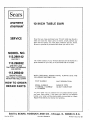
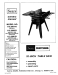
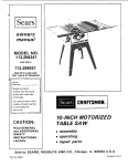
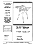
MODEL NO.
113.298142
SAW ON LY
113,298032
SAW WITH LEGS
TWO TABLE EXTENSIONS
AND MOTOR
113.298240
SAW WITH LEGS
TWO TABLE EXTEN SIONS
MOTOR AND HOLD DOWN
Serial
Number
_
_
Model and seria
number may be found
at the left-hand side
of the base.
You should
record both
model and serial number
in a safe place for
future use.
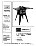
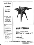
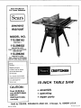
10-INCH
TABLE SAW
CAUTION:
• assembly
Read GENERAL
and ADDITIONAL
SAFETY
. operating
• repair
INSTRUCTIONS
parts
carefully
Sold by SEARS,
Part No. 62781
ROEBUCK
AND
CO.,
Chicago,
IL. 60684
U.S.A.
Printed
_n U.S.A.
FULL ONE YEAR WARRANTY
If withirl-one
year
workmanship,
States.
Sears
from
the
will
date
repair
of purchase,
this
it, free of charge.
WARRANTY
SERVICE
IS AVAILABLE
CENTER/DEPARTMENTTHROUGHOUT
ON CRAFTSMAN
Craftsman
This warranty
Table
applies
Saw
TABLE
fails
only while
BY SIMPLY
CONTACTING
THE UNITED STATES•
due
to
SAW
a defect
this product
THE
in material
or
is in use in the United
NEAREST
SEARS
SERVICE
This warranty gives you specific legal rights, and you may also have other rights which vary from state to state.
SEARS, ROEBUCK AND CO., Dept. 698/781A.
Sears Tower, Chicago, I L 60684
GENERAL SAFETY INSTRUCTIONS
FOR POWER TOOLS
1. KNOW YOUR POWER TOOL
Read
and
understand
affixed
limitations
peculiar
to
the owner's
manual
and
labels
the
tool
Learn
its application
and
as well as the specific
potential
hazards
to this tool.
2. GROUND
ALL TOOLS
This tool is equipped
with an approveo
3*conductor
cord and a 3-prong
grounding
type plug to fit the
proper grounding
tvpe receptacle.
The green conductor
in the cord is the grounding
wire. Never connect the
green wire to a live terminal.
3. KEEP GUARDS
in working
alignment.
IN PLACE
order,
and
in
4. REMOVE ADJUSTING
AND WRENCHES
proper
adjustment
and
KEYS
Cluttered
must
areas
and
not be slippery
6. AVOID
CLEAN
benches
invite
accidents,
Floor
due to wax or sawdust.
DANGEROUS
All visitors
area,
should
8. MAKE WORKSHOP
-- with
padlocks,
starter keys.
9. DON'T
from
work
KID-PROOF
master
switches,
or
by
removing
FORCE TOOL
It will do the job better
it web dc_igncd.
10. USE RIGHT
or attachment
to do a job it was not
11. WEAR PROPER APPAREL
GOGGLES
Keep proper
footing
15. MAINTAIN
and balance
at all times.
TOOLS WITH CARE
Keep
tools
sharp
and clean
performance,
Follow
instructions
changing accessories.
before
blades,
17. AVOID
Make
in.
the
safest
and
Follow
STAND
position
such
as
before
plugging
ACCESSORIES
manual
the
The
accessories
STARTING
is in "OFF"
owner's
the accessories.
cause hazards.
Serious
cutting
best and
lubricating
for
changing
ACCIDENTAL
sure switch
accessories.
for
TOOLS
servicing;
when
bits, cutters, etc.
for
recommended
instructions
use of
that
improper
accompany
accessories
may
ON TOOL
injury could occur if the tool
tool is accidentally
contacted.
is tipped
or if the
Do not store materials above or near the tool such that
it is necessary to stand on the tool to reach them.
Before
further
Check
parts,
PARTS
use of the tool,
for alignment
breakage
of
conditions
Do not wear loose clothing, gloves, neckties or jewelry
(rings, wrist watches) to get caught in moving parts.
Nonslip
footwear
is recommended.
Wear protective
hair covering to contain
long hair. Roll long sleeves
above the elbow.
12. USE SAFETY
of
a guard
or other
part that
is damaged should be carefully
checked to ensure that it
will operate properly
and perform
its intended function.
TOOL
Don't force tool
designed for.
periods
14. DON'T OVERREACH
20. CHECK DAMAGED
and safer at the rate for which
extended
Use clamps or a vise to hold work when practical.
It's
safer than using your hand, frees both hands to operate
tool.
19. NEVER
a safe distance
during
13. SECURE WORK
Consult
AWAY
be kept
or muffs)
18. USE RECOMMENDED
ENVIRONMENT
Don't
use power tools in damp or wet locations
or
expose them
to rain. Keep work
area well lighted.
Provide adequate surrounding
work space.
7. KEEP CHILDREN
(plugs
• 16. DISCONNECT
Form habit of checking
to see that keys and adjusting
wrenches
are removed
from tool before turning
it on.
5. KEEP WORK AREA
protectors
opera_ion
(Head Protection)
Wear Safety goggles (must comply
with ANSI Z87.1)
at all times.
Everyday
eyeglasses only have impact
resistant
lenses, they are NOT safety glasses. Also, use
face or dust mask if cutting operation
is dusty, and ear
that
other part that
or replaced.
21. DIRECTION
Feed work
of rotation
may
its
binding of moving
and any
other
operation.
should
A
be properly
guard
or
repaired
OF FEED
into a blade or cutter against
of the blade or cutter only.
power
complete
'affect
is damaged
22. NEVER LEAVE
UNATTENDED
Turn
of moving parts,
parts,
mounting,
off.
stop.
TOOL
Don't
the
direction
RUNNING
leave
tool
until
it comes
to a
ADDITIONAL
WARNING:
FOR
OPERATE
YOUR
ASSEMBLED
AND
INSTRUCTIONS...
AND UNDERSTAND
1.
SAFETY
YOUR
OWN
SAFETY,
DO
NOT
SAW
UNTIL
IT IS COMPLETELY
INSTALLED
ACCORDING
TO THE
AND
UNTIL
YOU
HAVE
READ
THE FOLLOWING.
2.
GENERAL
TOOLS...
GETTING
3.
4.
5.
6.
BASIC SAW OPERATION
. . . SEE PAGE
ADJUSTMENTS
. . . SEE PAGE 29
MAINTENANCE...
SEE PAGE 34
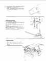
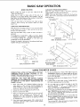
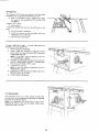
STABILITY
OF SAW
If there
INSTRUCTIONS
SAFETY
INSTRUCTIONS
SEE PAGE 2
TO KNOW YOUR SAW ...
is any tendency
FOR
(sawing entirely
thru
all loose pieces from
wood IMMEDIATELY
20
E.
23
for the saw to tip over or move
during
certain
cutting
operations
such as cutting
extremely
large heavy panels or long heavy boards, the
saw should be bolted down.
If you attach
any kind of table extensions
over 24"
wide to either end of the saw, make sure you either bolt
the saw to the bench or floor as appropriate,
or support
the outer end of the extension from the bench or floor,
SAWS
the work)
AND by removing
the table with a long stick of
after they are cut off
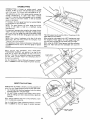
Use extra
caution
when
the guard assembly
is
removed
for
resawing,
dadoing,
rabbeting,
or
molding
replace
the guard as soon as that
operation
is completed.
For rip or rip-type
cuts, the following
end of a
workpiece
to which a push stick or push board is
applied must be square (perpendicular
to the fence)
in order that feed pressure applied to the workpiece
by the push stick
or block
does not cause the
D.
POWER
SEE PAGE
FOR TABLE
workpiece
to come
away
possibly cause a kickback.
During rip and rip type cuts,
held down on the table and
push
stick,
push
block,
J_a[berboard
is made of solid
F,
from
the
fence,
and
the workpiece
must be
against the fence with a
or featherboards.
A
lumber per sketch.
as appropriate.
7.
LOCATION
5/16"
The saw should be positioned
nor a casual observer
is forced
saw blade.
8.
G.
KICKBACKS
A "KICKBACK"
occurs during
a rip-type
operation
when a part or all of the workpiece
is thrown
back
violently
toward the operator.
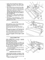
Keep your face and body to one side of the sawblade,
out of line with a possible "Kickback."
Kickbacks
and possible
injury
from
them --- can
usually be avoided by:
A. Maintaining
the rip fence parallel to the sawblade.
B. Keeping
the sawblade
sharp.
Replace or sharpen
antikickback
pawls when points become dull.
C.
D.
E.
F.
Keeping sawblade guard, spreader, and antikickback
pawls in place and operating
properly.
The spreader
must be in alignment
with the sawblade and the
pawls
must stop a kickback
once it has started.
Check their action before ripping.
NOT ripping work that is twisted or warped or does
not have a straight edge to guide along the rip fence.
NOT releasing work until you have pushed it all the
way past [he sawblade.
Using a push stick for ripping widths of 2 to 6 in.,
and an auxiliary
fence and push block for ripping
widths
narrower
than
2 in.
(See "Basic
Saw
Operation
9.
Using The
G.
NOT confining
cross-cutting.
H.
When ripping
the workp!ece
fence.
the
Rip Fence"
cut off
piece
C.
Wear safety
and a face
plugs
or
H.
I,
J.
when
ripping
or
apply the feed force to the section of
between
the saw blade and the rip
NEVER
turn
the saw "ON"
before clearing
the
table
of all tools,
wood scraps, etc., except
the
workpiece
and related
feed or support
devices for
the operation
planned.
NEVER
place your face or body in line with the
cutting tool.
NEVER
place your fingers or hands in the path of
the sawblade or other cutting tool.
NEVER
reach in back of the _,t]tting tool with
either hand to hold down or support the workpiece,
remove wood scraps, or for any other reason. Avoid
awkward
operations
and hand positions
where a
sudden slip could cause fingers
or hand to move
into a sawblade or other cutting tool.
K. DO NOT perform
layout, assembly, or setup work
on the table while the cutting tool is rotating.
L DO NOT perform
any operation
"FREEHAND"
-always use either the rip fence or the miter gauge to
position
and guide the work.
M. NEVER
use the rip fence when crosscutting
or the
miter
gauge when ripping.
DO NOT use the rip
fence as a length stop.
Never hold onto or touch
the "free end" of the
section.)
N.
workpiece
or a "free piece"
that is cut off, while
power is "ON"
and/or the sawblade is rotating.
Shut "OFF"
the saw and disconnect
the power cord
when
cutting
removing
the
tool, removing
table
insert,
changing
the
or replacing the blade guard,
or making adjustments.
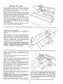
Provide adequate
support
to the rear and sides of
the saw table for wider or long workpieces.
P. Plastic and composition
(like hardboard)
materials
may be cut on your saw. However, since these are
usually
quite
hard and slippery,
the antikickback
pawls may not stop a kickback.
Therefore,
be especially
attentive
to following
proper
set-up and cutting
procedures
for ripping.
Do not stand, or permit anyone else to stand, in line
with a potential
kickback.
O. If you stall or jam the sawblade in the workpiece,
turn saw "OFF",
remove the workpiece
from the
sawblade,
and check
to see if the sawbtade
is
parallel
to the miter
gauge grooves
and if the
spreader is in proper alignment
with the sawblade.
If ripping at the time, check to see if the rip fence is
O.
PROTECTION:
EYES, HANDS,
FACE, EARS, BODY
A. If any part of your saw is malfunctioning,
has been
damaged or broken..,
such as the motor switch, or
other
operating
control,
a safety
device
or the
power
cord ...
cease operating
immediately
until
the particular
part is properly
repaired or replaced.
B.
APART
so neither
the operator
to stand in line with the
goggles that comply
with ANSI Z87.1,
shield if operation
is dusty. Wear ear
muffs
during
extended
periods
of
operation.
Small loose pieces of wood or other objects
that
contact
the rear of the revolving
blade can be
thrown
back at the operator at excessive speed. This
can usually
be avoided by keeping
the guard and
spreader
in place for
all thru-sawing
operations
parallel
with
the sawblade.
Readjust
as indicated.
R. DONOTremove
smallpieces
of cutoff material
that maybecome
trappedinsidethe bladeguard
whilethesawisrunning.
Thiscouldendanger
your
handsor cause
a kickback.
Turnsaw"OFF"and
waituntilbladestops.
S. Useextracarewhenripping
woodthathasatwisted
grainor istwistedor bowed- it mayrockonthe
tableand/orpinchthesawblade.
10.KNOW
YOURCUTTING
TOOLS
A Dull,gummy,
or improperly
sharpened
orset cutting
B.
tools can cause material to stick, jam, sta!l the saw,
or kickback
at the operator.
Minimize
potential
injury
by proper
cutting
tool
and machine maintenance.
NEVER
ATTEMPT
TO
FREE
A STALLED
SAWBLADE
WITHOUT
FIRST
TURNING
THE
SAW OFF.
Never use grinding
wheels, abrasive cut-off
wheels,
friction
wheels (metal slitting
blades) wire wheels or
buffing wheels.
11. USE
ONLY
ACCESSORIES
DESIGNED
FOR
THIS
SAW.
12. Crosscutting
operation_
are more conveniently
worked
and with greater safety if an auxiliary
wood facing is
attached
to the miter gauge using the holes provided.
However, the facing must not interfere
with the proper
functioning
of the sawblade guard.
13. Make sure the top of the arbor or cutting
tool rotates
toward
you
when
standing
in normal
operating
position.
Also make sure the cutting
tool, arbor collars
and arbor nut are installed properly.
Keep the cutting
tool
as low
as possible
for
the operation
being
0erformed:
Keeo all guards in place whenever
possible,
14. Do not use any blade or other cutting tool marked for
an operating
speed less than 3450 RPM. Never use a
cutting
tool
larger in diameter
than the diameter
for
which
the saw was designed.
For greatest safety and
efficiency
when ripping,
use the maximum
diameter
blade for which
the saw is designed, since under these
conditions
the spreader is nearest the blade.
DO
NOT
pull
the
workpiece
through
the
sawblade
-
position your body at the nose (in-feed) side of the guard:
start and complete
the cut from the same side. This will
require added table support for long or wide workpioces
that extend beyond the length or width of the saw table.
18.THINK
Safety
SAFETY.
is a combination
of operator
common
sense and
alertness at all times when the saw is being used.
19. NOTE
AND
FOLLOW
SAFETY
INSTRUCTIONS
THAT APPEAR
ON THE FRONT
OF YOUR SAW.
FOR YeUR
READ
1
AND
WEAR
OWN SAFETY
UNDERSTAND
OWN£R'S
BEFORE
OPERATING
SAFETY
GOGGLES
M_.NUAL
MACHINE:
PER ANSI Z871
AT ALL
TIMES
1
USE SAW
BLADE
GUARD
FOR
"TI-IRU
SAWING'"
KEEP
HANDS
OUT
OF PATH
OF $AWBLADE
USE
l i
A
KNOW
*'PL_H.SlrlCK
HOW
'' WHEN
DANGER
AVOID
"KICK
TO
De NOT PERFORM
NEVER
REACH
REOU)RED
RACRS"
OPERATleNS
AROUND
eR
"FREEHAND"
eVER
SAW
BLADE
20.WARNING:
DO
NOT
ALLOW
FAMILIARITY
(GAINED
FROM
FREQUENT
USE OF YOUR
SAW)
TO
BECOME
COMMONPLACE.
- ALWAYS
REMEMBER
THAT A CARELESS
FRACTION
OF A
SECOND
IS SUFFICIENT
TO
INFLICT
SEVERE
INJURY,
21.WARNING:
THE 2-1/2"" SAW PULLEY AND THE
2-1/2" MOTOR PULLEY FURNISHED,
WILL RUN
THE
BLADE AT APPROXIMATELY
3450 RPM
WHEN USED WITH A 3450 RPM MOTOR. NEVER
SUBSTITUTE THESE PULLEYS TO INCREASE THIS
SPEED BECAUSE IT COULD BE DANGEROUS.
NOTE:
to just
Do not overtighten
"snug"
it.
arbor
WEAR
nut.
Use the arbor
wrench
YOUR
15. Adjust
table inserts flush with the table top. NEVER
operate the saw unless the proper insert is installed.
16. NEVER
rear of
result
feed material
into the cutting
too
from the
the saw. An accident
and serious
njury could
17. NEVER
use another
person
as a substitute
for a table
extension
or as additional support for a workpiece that
is longer or wider than the basic saw table, or to assist in
feeding
or supporting
MOTOR
or pulling
the workpiece
SPECIFICATIONS
This saw is designed
use any motor that
AND
to use a 3450 RPIV motor only. Do not
runs faster than 3450 RPM. It is wireo
for operation
on 110-120 volts, 60 Hz., alternating
current.
IT MUST NOT BE CONVERTED
TO OPERATE
ON 230
VOLTS.
EVEN
THOUGH
SOME
OF
THE
RECOMMENDED
MOTORS
ARE
DUAL
VOLTAGE.
Changing
changing
to 230 volt wil not conserve
the power cord plug.
The Outlet in the
motor plug.
switch
box will
RECOMMENDED
THIS SAW.
CRAFTSMAN
energy
accept
MOTORS
and requires
only a 15 amp.
FOR
The operation
objects
being
of any power tool
can result in foreign
thrown
into
the eyes, which
can result in
severe eye damage. Always
wear safety goggles complying
with
ANSI Z87.1 I;hown
on Package) before commencing
power tool operation.
Safety Goggles are available at Sears
retail or catalog stores.
ELECTRICAL
CONNECTING
REQUIREMENTS
TO POWER
SOURCE
OUTLET
This saw must be grounded
operator from electrical shock
while
If power cord is worn
it replaced immediately,
or damaged
or cut,
If your saw is for use on less than
that looks like below.
n use to protect
in any way, have
150 volts
3-PRONG
it has a alug
PLUG
USE ON
H.P.
R.P.M.
Volts
Catalog
1
3450
110-120
1217
1
3450
110-120
1220
No.
CAUTION:
Do not use blower or washing machine motors
or any motor with an automatic reset overload protector as
their use may be hazardous.
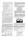
GROUNDING
_PROPERLY
3NRONG
the
PRONG
GROUNDED
OUTLET
Plug power cord into
110-120V
properly
outlet
protected
by a 15-amp. time delay
fuse or circuit
breaker.
IF
YOU
ARE
PROPERLY
QUALIFIED
NOT
SURE
GROUNDED,
ELECTRICIAN.
WARNING:
DO
THE TERMINALS
REMOVING
THE
THAT
HAVE
grounded
type
or Circuit-Saver
LUG
ADAPTER
YOUR
IT
GROUNDING
OUTLET
CHECKED
IS
BY
MAKE
A
3-PRONG
SURE
THIS
CONNECTED
PLUG
KNOWN
NOT PERMIT
FINGERS
TO TOUCH
OF PLUG
WHEN
INSTALLING
OR
PLUG TO OR FROM THE OUTLET.
TO
IS
A
GROUND
2-PRONG
RECEPTACLE
WARNING;
IF NOT
PROPERLY
GROUNDED
THIS
POWER TOOL CAN INCUR
THE POTENTIAL
HAZARD
OF
ELECTRICAL
SHOCK,
PARTICULARLY
WHEN
USED
IN DAMP
LOCATIONS,
IN
PROXIMITY
TO
PLUMBING,
OR OUT OF DOORS.
IF AN ELECTRICAL
SHOCK
OCCURS
THERE
IS THE POTENTIAL
OF A
SECONDARY
HAZARD
SUCH
AS YOUR
HANDS
CONTACTING
This
saw
THE
is
SAWBLADE.
equipped
with
a
3-conductor
cord
and
grounding type plug which has a grounding
prong, approved
by Underwriters'
Laboratories
and the Canadian Standards
Association.
The ground conductor
has a green lug and is
attached to the too! housing at one end and to the ground
prong in the attachment
plug at the other end.
This
plug requires
outlet as shown.
a mating
3-conductor
grounded
NOTE: The adapter illustrated
is for use only
have a properly
grounded 2-prong receptacle.
if you already
The
some
An adapter
to 2-prong
you have a qualified
outlet
with a properly
cord
will
cause
loss
of
to a minimum
and to prevent
burn-out,
use the table below to
wire size (A.W.G.)
extension
cord.
cords
which
have 3 prong
3-pole
receptacles
which
will
110-120V
Wire Size A.W.G.
Up to 50 Ft .................
14
50 to 100 Ft ................
12
100-200
Ft .................
10
200-400
Ft .................
8
CHECK MOTOR
ROTATION
WARNING:
FOR YOUR OWN SAFETY, MAKE SURE
PLUG IS NOT CONNECTED
TO POWER SOURCE
OUTLET WHEN CHANGING MOTOR ROTATION.
as shown below is available for connecting
plugs
receptacles.
The green grounding
lug extending
from the adapter must be connected
to a permanent
such as to a properly
grounded outlet box.
extension
1 H.P. MOTOR
Extension Cord Length
type
electrician
grounded
any
Use only
3 wire extension
grounding
type
plugs and
accept the plug on the saw.
If the outlet you are planning
to use for this saw is of the
two prong
type
DO NOT
REMOVE
OR ALTER
THE
GROUNDING
PRONG IN ANY MANNER.
Use an adapter
as shown and always connect the grounding
lug to a known
ground.
It is recommended
that
replace the TWO prong
TH REE prong outlet.
use of
power.
To
keep this
over-heating
and motor
determine
the minimum
ground
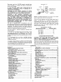
The motor must rotate CLOCKWISE when viewed from the
shaft end to which you witl mount the pulley. (See page
16.) If it does not, change the direction according to the
instructions furnished with the motor.
CONTENTS
WARRANTY
......................................
GENERAL SAFETY INSTRUCTIONS
FOR POWER "TOOLS ............................
ADDITIONAL SAFETY INSTRUCTIONS
FOR TABLE SAWS ..............................
MOTOR SPECIFICATIONS
AND ELECTRICAL
REQUIREMENTS
...............................
UNPACKING AND CHECKING CONTENTS
........
Tools Needed ...................................
List of Loose Parts ..............................
ASSEMBLY
.......................................
Installing Handwheels
...........................
Checking Table Insert ...........................
Checking Blade Squareness to Table .............
Assembling Steel Legs ...........................
Mounting Saw ...................................
Attaching Table Extensions
.....................
Installing Rip Fence Guide Bars .................
Aligning Rip Fence .............................
Adjusting Rip Scale Indicator
...................
Installing Blade Guard ..........................
Mounting the Motor ............................
Installing Belt Guard ...........................
Assembling Hold-Down
.........................
Plugging in Motor ..............................
GETTING TO KNOW YOUR SAW .................
On-Off Switch ..................................
Elevation Handwheel
...........................
Tilt Handwheel
.................................
Tilt Lock Handle ...............................
Rip Fence ......................................
Miter Gauge ...................................
Blade Guard ...................................
2
2
3
4
6
6
6
8
8
8
8
9
9
10
10
12
14
14
16
18
19
19
20
20
21
21
21
21
21
21
Table Insert ....................................
Removing and Installing Sawblade
..............
Exacti-Cut
.....................................
BASIC SAW OPERATION USING THE MITER GAUGE
Work Helpers
..................................
Crosscutting
...................................
Repetitive Cutting
..............................
Miter Cutting .... . ..............................
Bevel Crosscutting
.............................
Compound Miter Cutting
.......................
Using the Hold-Down
..........................
BASIC SAW OPERATION USING THE RIP FENCE
Ripping ........................................
Bevel Ripping ..................................
Ploughing and Molding .........................
Resawing ......................................
Cutting Panels .................................
Rabbeting ......................................
Dadoing
.......................................
Using Featherboards
......................
.....
ADJUSTMENTS
..................................
Miter Gauge ...................................
Heeling Adjustment or Parallelism of
Sawblade to Miter Gauge Groove
..............
Blade Tilt, or Squareness of
Blade to Table ................................
Tilt Mechanism .................................
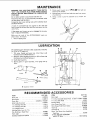
MAINTENANCE
..................................
LUBRICATION
...................................
RECOMMENDED
ACCESSORIES
.................
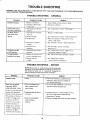
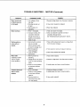
TROUBLE SHOOTING
...........................
REPAIR PARTS ..................................
21
22
22
23
23
24
24
25
25
25
26
27
27
27
29
29
29
29
30
30
31
31
31
32
34
35
35
35
36
38
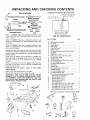
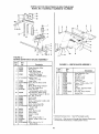
UNPACKING
AND CHECKING
CONTENTS
COMBINATION
SQUARE
NEEDED
MUST
BE TRUE.
STRAIGHT EDGE OF BOARD
3,/4"
DRAW LIGHT
BOARD ALONG
Medium Screwdriver
Small Screwdriver
LINE ON
THICK.
THIS
EDGE
MUST
BE PERFECTLY STRAIGHT.
THIE EDGE, <_'\x
Phillips Type
___rewdriver
Wrenches
_,'+'Tr!;iiii_il
I:III_,L.'III:II',III!I
ii.11'i::]ii_ii' I
Combination
/
3/8 In.
7/16 in.
1/2 in.
9/16 In.
3/4 In.
Square
SHOULD BE NO GAP OR OVERLAP
HERE WHEN SQUARE IS FLIPPED
OVER
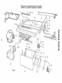
Model
carton
113.298142
but DOES
Table Saw is shipped
NOT INCLUDE
Table
complete
in one
Extension,
Steel
IN
DOTTED
POSITION.
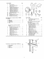
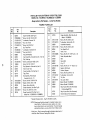
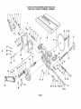
LIST OF LOOSE PARTS
Legs, or motor.
Model 113.298032
Table Saw is shipped complete
in one
carton
but INCLUDES
Two Table Extensions,
Steel Legs,
and Motor.
Model
carton
Motor,
Item
113.298240
Table Saw is shipped complete
in one
but INCLUDES
Two Table Extensions,
Steel Legs,
and Hold Down.
Separate
one with
all parts from
the illustration
certain
all items
packing material.
packing
materials
and check each
and the list of Loose Parts to make
are accounted
for.
before
discarding
any
f any parts are missing, do not attempt
to assemble the
table saw. plug
n the power cord or turn the switch on
until
the missing
parts
are obtained
and are installed
correctly.
Remove the protective
oil that is applied
and edges of the table. Use any ordinary
grease and spo_ remover.
CAUTION:
Never
volatile solvents.
Apply
use gasoline,
a coat of automobile
Wipe all parts thoroughly
WARNING:
CONNECT
FOR
PLUG TO
naptha
to the table top
household
type
or
similar
highly
wax to the table.
with
a clean, dry cloth.
YOUR
POWER
OWN
SAFETY,
SOURCE
OUTLET
NEVER
UNTIL
ALL ASSEMBLY
STEPS ARE COMPLETE,
AND
HAVE
READ
AND UNDERSTAND
THE SAFETY
OPERATIONAL
INSTRUCTIONS.
A
B
YOU
AND
....C
Part Name
Qty.
A
B
C
Blade Guard and Spreader ..................
Rip Fence ..............................
Owners Manual ..........................
1
1
1
D
E
Miter Gauge ............................
Arbor Nut Wrench* .......................
F
6
H
J
K
Switch w/Key
...........................
Rip Fence Guide Bar with Rip Scale (Front] ....
Handwheel
.............................
V-Belt 1/2 in. x 41 in.* ....................
Pulley, 2-1/2 in. die., with 5/8 in. bore*
.......
1
1
2
1
1
L
M
N
0
P
Q
R
S
T
U
V
1
3
2
1
1
1
1
1
1
1
1
W
W
W
Belt and Pulley Guard .....................
Belt Guard Clip ..........................
Self-Threading Screw, 10 32 x 1/2 in. long .....
Belt GLard Support .......................
Belt Guard Support Brackel
................
Motor Base .............................
Spreader Rod*
. .........................
Blade Guard Support with Screw*
...........
Spreader Support * .......................
Rip Fence Guide Bar (Rear) ............
....
Ri!c Fence Guide Bar Rod ..................
"Pkg. of Miscellaneous Smell Parts No. 62751
Consisting of the Following:
Setscrew Wrench 3/32 in ................
Setscrew Wrench 1/8 in .................
Setscrew Wrench. 5/32 in ................
X
Y
Y
Y
Y
Y
Self-Threading Nut
....................
Hex Head Screw, 5/16-18 x 1-3/4 in. long ...
Hex Head Screw. 5/16-18 x 5/8 in. t0ng ....
Hex Head Screw, 5/16-18 x 1 in. long ......
Hex Head Screw, 1/4-20 x 5/8 in. 10ng .....
Hex Head Screw, 5/16-18 x 3/4 in. long ......
2
2
3
4
2
2
.
1
1
1
1
1
*These parts are packaged in Loose Parts Bag No. 62750
LENGTH
s=zE
/
AA
AB
L
K
J
Y
X
AC
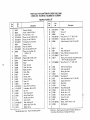
ItemPart Name
Z
Z
AA
AA
AA
AB
AC
AD
AE
AF
AG
Qty.
Hex Nut, 5/16-18
(approx.die. of hole 5/16 in.) ...........
Hex Nut, 1/4-20
(approx.die. of hole1/4 in.) ............
Lockwasher,5/16 in. ExternalType
(approx.die. of hole 5/18 in.) ...........
Lockwasher,1/4 in. ExternalType
(approx.die. of hole 1/4 in.) ............
LockwasherNo. 10 ExternalType
(approx.dia. of hole3/16 in.) ...........
CarriageBolt, 5/16-18 x 3/4 in. long .......
Rip FenceGuideBarSpacer ..............
Wire Tie ...............................
Thumbscrew, 5/18-18 x 1 in. long ..........
ScrewPanHd. 10-32 x 3/4 ..............
Flat Washer(die. of hole 21/64) ...........
A
9
2
11
2
1
4
2
2
1
1
2
Leg ...................................
Side Stiffener ...........................
End Stiffener ............................
Table Extension ...................
Motor .................................
4
2
2
2
1
G
H
H
H
J
Hex Head_crew 5/16-18 x 1-I/4 in. long ....
Loekwasher,1/4 in. ExternalType
(approx.dia.of hole 1/4 in.) ..............
Lockwasher,5/16 in. ExternalType
(approx. die. of hole 5/t6 in.) ............
Hex Nut, I/4-20
(approx. dia. of hole 1/4 in.) .............
Hex Nut, 5/16-18
(approx.die. of hole5/16 in.) .............
Hex Nut, 1/2-13
(approx.die. of hole 1/2 in.) .............
Flat Washer(die. of hole, 11/32 in.) .........
The Hold Down is included with Model 113.298240
only.
L
M
N
Qty.
K
Truss Head Screw, 1/4-20
L
(top of screw is rounded) ................
Leveling Foot
.........................
x 5/8 in. long
2 ea. for Model 113.298032
8., 113.298240
Consisting of the following:
Hex Hd. Screw, 5/16-18 x 1-1/4 in. long .....
Lockwasher, External Type
(approx. die. of hole 1/4 in.)
'
Loekwasher, External Type
(approx. die. of hole 5/1G in.) .............
Hex Nut, 1/4-20
(approx. die. of hole 1/4 in.) ..............
Hex Nut, 5/16 18
(approx. dia. of hole 5/16 in.) .............
24
H
4
H
24
J
J
Flat Washer (die. of hole 17/64 in.)
Flat Washer (die. of hole 11/32 in.)
4
K
8
8
M
N
Truss Head Screw, 1/4-20 x 1 in. long
(top of screw is rounded)
................
Corner Stiffener Bracket ..................
Corner Support Bracket ..................
Qty.
I
2
2
D
Support
1
24
4
Pkg. of Miscellaneous Small Parts No. 62745 for
Table Extensions.
G
Clamp Assembly ..........................
Wing Screw .............................
Washer .................................
............................
K
H
4
A
B
C
Rod
J
F
G
Pkg.of Miscellaneous
Small Parts No. 62752
for Legs
F
G
G
Item Part Name
The following parts are includedwith Model 113,298032
and 113.298240.
A
B
C
D
E
©
_"_D
.........
.........
4
8
4
8
4
2
4
8
2
2
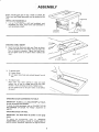
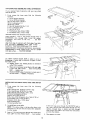
ASSEMBLY
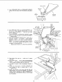
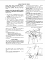
Before mounting
the saw on legs, a stand or a bench, the
Table Insert and Blade Squareness must be checked
at this
time.
LOC:KWASHER
INSTALLING
1.
HANDWHEE
/
LS
Line up FLAT SPOTS on shaft and handwheel,
push
handwheel
onto shaft. Install screw and Iockwasher
to
lock handwheel
on shaft.
ELEVATION
HANDWHEEL
CHECKING
2.
TABLE
INSERT
Insert should be flush with table top. Check as shown.
Loosen flat head screw tha_ holds insert and adjust the
four set screws as necessary. Tighten
flat head screw•
Do not tighten screw to the point where it deflects the
insert.
3/32 IN
SETSCREWWRENCH
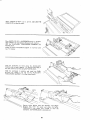
3.
To remove
insert•
A)
Loosen
Screw
B)
Lift
insert
from
front
end. and pull
toward
front
of
saw,
To replace
insert.
Place insert
into
insert
opening
in table
toward
rear of saw to engage spring clip
keyslot in insert will drop over screw. Tighten
Do not tighten
the insert.
CHECKING
screw
to the point
where
CHECKING
IMPORTANT:
it will
deflect
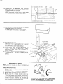
BLADE SQUARENESS TO TABLE
IMPORTANT:
I_LADE must be _QUARE
in order to proceed with assembly.
To check for
SQUARENESS
page 32.
and push
and until
screw.
(90 O) to TABLE,
blade squareness, refer to "BLADE
TILT,
OF BLADE
TO TABLE"
adjustment
BLADE
FOR
OR
on
HEEL
Saw blade MUST
be parallel
to miter
gauge
groove.
To
check
for
parallelism,
refer
to
"HEELING
ADJUSTMENT
OR PARALLELISM
OF SAVBLADE
TO
MITER GAUGE GROOVE"
adjustment on page 31 and 32.
TILT
10-32 X 3/4 IN.
PAN HEAD SCP_W
/
rtANDWHEEL
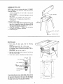
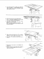
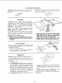
ASSEMBLING
STEEL LEGS
NOTE:
Steel Legs are furnished
and 113.298240.
From among
following
Hardware:
24 Truss Head Screws,
screw is rounded)
24 Lockwashers,
hale 1/4 in.)
24 Hex Nuts,
8 Hex Nuts,
4 Leveling
Assemble
1.
2.
1/4 - 20 x 5/8
in. long
(top of
(approx.
dia. of
SIDE STIFFENER
1/4 in. External
1/4 - 20 (approx.
1/2 - 13 (approx.
Type
dia. of hole
dia. of hole
I/4
in.)
1/2 in.)
feet.
the legs as shown
...
Insert the Truss Head Screws through
the holes in the
legs, then through
the holes in the stiffeners.
MAKE
SURE THE SCREWS GO THROUGH
THE HOLES IN
THE SIDE STIFFENERS
MARKED
"X "°.
Install
the
not tighten
3.
wLth Model
113.298032
the loose parts, find the
Install
Iockwashers
until
leveling
...
completely
screw
on the
nuts
but
END
STIFFENER"
do
assembled.
feet.
IN.
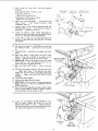
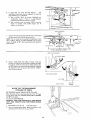
MOUNTING
1.
SAW
From
among
hardware:
the
4 Hex Head Screws,
loose
5/16
parts,
find
- 18 x 1-1/4
the
following
in. long.
4 Hex Nuts, 5/16 - 18 (approx. dia. of hole 5/16
4 Lockwashers,
5/16 in. External Type (approx.
hole, 5/16 in.)
8 Flat Washers, (dia. of hole 11/32 in.)
2.
3.
Place saw on legs so that
with holes in top of legs.
Instatl
HEX NUTS
screws,
washers,
holes in bottom
Iockwashers
of saw line up
and nuts as shown.
SAW BASE
HEX
H A0
SCREW
FLAT
END
in.)
dia. of
[
7/]6
1
i
_E_
"
FLAT WASHER----__
LOCKWASHER "I'"_'
HEX N UT '_"_'_U_
STIFFENER-"-_1
1
If you mount the saw on any other bench, make sure that
there is an opening in the top of the benc h the same size as
the opening
in the bottom
of the saw so that the sawdust
can drop through.
Recommended
working
height is 33 to
37 inches from the top of the saw table to the floor.
DIA
HOLES
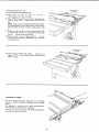
ATTACHING
AND
ASSEMBLING
TABLE
If you
received
Table
them at this time.
Extensions
1.
loose
From
among
hardware.
the
Support
Stiffener
with_ou,r
parts
find
4
4
Corner
Corner
16
16
16
8
8
8
Truss Hd. Screws 1/4-20 x 1
Ext. Lockwashers
1/4
Hex Nut I/4-20
Hex Hd. Screws 5/16-18x
1-1/4
Ext. Lockwasher
5/16
Hex Nut5/16-18
Flat Washers
(Dia. of hole 17/64)
8
Flat Washers
(Dia.
brackets
ONS
Saw attach
the
following
Brackets
Brackets
4
Assemble
i:XTENS
with
of hole 11/32)
hardware
as listed.
Insert 5/16-18
x 1-1/4
in. long screws through
holes in
EXTENSION
then
through
table.
Install
flat
washer,
Iockwashers,
and screw
on the nuts . . . DO NOT
TIGHTEN.
Align
Pull
front edge of extension
Extension
UPWARDS
SLIGHTLY
TIGHTEN
BLOCK OF WOOC
\
with front edge of saw table.
above table
surface
...
SCREWS
using
1/2 in. wrench.
Using small block of hardwood
and hammer, tap extension
DOWNWARDS
at front,
center & rear, until it is EVEN
with table surface ... TIGHTEN
SCREWS.
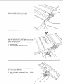
Lay
REAR
FENCE
straightedge.
If outer
than table surface;
GUIDE
BAR
on table to
edge of extension
is higher
holding
bracket
act as a
or lower
A.
Slightly
loosen nuts
using 7/16 in. wrench.
to extension
B.
Move end of extension
u _ or down until outer edge
is even with
table surface
...
check with GUIDE
BAR
... tighten nuts.
C.
Recheck
INNER
edge of extension
to make
has not moved
... readjust, if necessary.
sure it
\
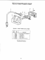
INSTALLING
BOX
RIP FENCE GUIDE
From
among
hardware:
the
loose
parts
\
BARS AND SWITCH
find
the
following
2 Hex. Head Screws, 5/16-18 x 1-3/4 in. long
2 Hex. Head Screws, 5/16-18 x 1 in. long
2 Hex. Head Screws 5/1&18
x 3/4 in. Ion_
6 External
Lockwashers,
5/16 in.
(approx. dia. of hole 5/16 in.)
6
2
2
2
1
Hex. Nuts, 5/16-18
(approx. dia. of hole 5/16
Flat washers (dia. of hole 21/64 in.)
Spacers, 3/4 in. dia. x 1/2 in. long
Self-threading
nuts
Fence Guide Bar Rod
Lay guide
in.)
/
/
bars on saw table.
1-3/4
NOTE:
The various holes in the bar allow them to be
positioned
on this saw and also makes them adaptable
to other models.
3.
inch
long
screw
through
the
SEVENTH
hole
in
bar. Insert two 3/4 inch long screws through
two flat
washers,
through
holes in switch,
and then through
holes EIGHT
and TEN in bar. Instal
two Iockwashers
and nuts then tighten.
Insert a 1-3/4 inch tong screw through the THIRD
hole
from
LEFT
IN THE FRONT
BAR ...
Insert another
4.
10
Place spacers on screws.
Insertboltsthroughholesin
front
of
saw
table
...
middle and on right side of
install
Iockwashers
and nuts.
DON'T
SCREW
NUTS
ON
them started on the screws.
6.
7.
Remove
the 3 screws from
ALL
THE
rear of table
WAY,
just
extension.
Insert 1 in. long screws in SECOND and FOURTH
of rear bar and attach to table the same way.
Insert
round
ends of FENCE
GUIDE
holes at outer end of bars.
BAR
get
ROD
holes
through
NOTE: The ends of the ROD are not threaded
... the
SELF THREADING
NUTS will cut threads on the rod
as they
9.
Hold
are screwed
rod with
pliers start
OR TWO...
10.
Using TWO
the nuts.
on.
one hand
and with
a 1/2 in. wrench
or
screwing on ONE of the nuts only A TURN
screw on other nut the same way.
1/2
in. wrenches
11, Slide the bars so that
slotted holes.
screws
12. Position
rip fence over miter
the rear end while
engaging
lower fence onto table.
or pliers
tighten
are in the MIDDLE
both
of
of the
gauge groove, holding
front
end with
bar
up
...
11
8 THICKNESSES
OF PAPER
13, Raise blade all the way up,
14. Carefully
move fence against
15. Move
front
approximately
blade.
bar
until
"'0"" mark
inline with indicator.
on
rip
scale
is
16. Move FRONT
bar upwards until fence is approximately
1/32 in. above table
...
tighten
screw at left end of
bar.
NOTE:
Fold a piece of newspaper making 8 thicknesses
and place between rip fence and table to act as a spacer.
This will hold the fence off of the table approx.
1/32
in.
17. Adjust
rear bar so that the fence is approximately
in. above table make sure it is square with fence
bar rod ... tighten screw at end of bar.
18. Replace
screws
in rear of
top surface of extension
of rear guide bar.
table
extension
is PARALLEL
. ..
to top
1/32
guide
be sure
surface
8 THICKNESSES
OF PAPER
19. Move fence to RIGHT edge of table ...
approx.
1/32 in. above table at front
tighten screws,
ALIGNING
make sure it is
and rear and
RIP FENCE
The fence should slide easily along the
remain
in alignment
(parallel to sawblade
grooves),
bars and always
and miter gauge
The alignment
is maintained
by a spring underneath
fence which bears against the front guide bar.
To move the fence, loosen the
fence with one hand at the front.
lock
handle
the
and grasp the
12
For very close adjustments, grasp the guide bar with both
hands and move the fence with your thumbs,
Place fence on saw but DO NOT
LOCK
IT.
Move the REAR
END of the fence slightly
to the right or
left
...
when you release it, the fence should "spring"
back to its original position.
If it does not, the spring
1. Loosen the screws.
pressure
2.
toward
Move Spring
slightly
If the fence does not slide easily
of the spring can be REDUCED.
1.
Loosen
2.
Move
must be INCREASED.
front
of fence.
along the bars, the pressure
the screws.
spring
slightly
SPRING
toward
rear
of
fence
...
tighten
3crew3.
5CR_WS
13
SCREWS
The rip fence must be PARALLEL
with
(see page 31) ana miter Gauge grooves..
until
it is along side of groove. Do NOT
should be parallel to groove. If it is not;
3,
Loosen
B.
Hold fence head tightly
aga=nst bar . . move end
of fence so that it is parallel with groove.
C.
Alternately
1. Turn
"'Hex.
FENCE HEAD
A.
ADJUSTING
the two
the sawblade
Move fence
LOCK IT. !t
tighten
Head Screws."
the screws.
RIP SCALE INDICATOR
ELEVATION
HANDWHEEL
TABLE,
in order
to ALIGN
clockwise
\
until
LOCK HANDLE
blade is up as high as it will go.
IMPORTANT:
BLADE
must
be SQUARE
{90 °)
to
rip fence.
2.
Using a rule, position
fence on right side of sawblade 2
in. from tt_e sides of the teeth..,
tighten
lock handle.
3.
Loosen screw holding the indicator..,
adjust so that
points to "2" on the rip scale..,
tighten screw.
it
NOTE:
If you cannot adjust indicator
so that it points
to "2",
loosen the screws holding
the front guide bar
and move the guide bar.
INSTALLING
1.
From among
BLADE
GUARD
the loose parts, find
2 Hex Head Screws,
1/4 - 20x
2 Hex Head Screws,
5/16-
5/8
18x
in. long
5/8in.
......
long
2 Hex Head ScrewS, 5/1618 x 1 in. long
2 Hex Nuts, I/4 - 20
(approx. dia. of hole 1/4 in.)
2 Lockwashers,
1/4 in. External
(approx. dia. of hole 1/4 in.)
2 Lockwashers, 5/16 in. External
(approx. dia. of hole 5/16 in,)
1 Thumbscrew
Guard Support
Spreader
Support
Spreader
Rod
GUARD SUPPORT
5/]6_18
Type
HEX
SCREW
Type
.........
5/16-18
X 1' IN.
HEX HD. SCREW
2,
Lower
the blade ..........
3.
Screw the two MOTOR
way into cradle.
4.
Attach
screws.
GUARD
X
BASE
SUPPORT...
CLAMP
DO
SCREWS
NOT
part
TIGHTEN
14
THUMB SCREW
SPREADER
5o
Insert
until
it.
SPREADER
pin fits into
ROD
notch.
int0SPREADER
Insert
SUPPORT
Thumbscrew
X
ROD
\
and tighten
FLAT
SURFACE
SPREADER
SUPPORT
SUPPORT)
_,
(INTO
_,
U
6.
7.
Slide SPREADER
ROD into
left
end of ROD
extends
GUARD
SUPPORT
approximately
1/4
until
inch
beyond
edge of SUPPORT
Screw in SUPPORT.
..,
Head
Attach
screws
SPREADER
to SPREADER
up
Hex
SUPPORT
are all the way back in the SLOTS
•. • tighten
8.
Snug
1/4-20
HEX
HD. SCREW
1/4 IN.
LOCKWASHER
1/4-20
HEX NUT
so that
of SUPPORT
screws.
Raise ANTIKICKBACK
PAWLS
(hold in place with a
setscrew
wrench
see below)..,
align
spreader
SQUARE
to _able (be sure insert is properly
adjusted).
NOTE:
"true"
The framing
(or combination)
square
see start of "assembly
and alignment"
on page 6 for checking
•..
Tighten
both
END OF ROD
1/4 INCH
TO LEFT
OF EDGE OF
must be
section
method.
5/16-18
SUPPORT
x 1 in. HEX
HEAD
SCREWS.
GUARD
SUPPORT
SCREWS ALL
WAY
9.
Raise blade
with table.
all the
way
up
...
make
sure it is square
10. Raise Blade Guard ...
lift up both ANTIKICKBACK
PAWLS ... insert one of the SETSCREW
WRENCHES
in the notches
11. Lay blade
blade.
12. Loosen
to hold the pawls
of square
Hex
Head
move spreader
so
• . . tighten screw.
or other
Screw
that
out of the way.
straightedge
in GUARD
it
touches
alongside
SUPPORT
blade
of
of
and
square
13. NOTE:
The spreader is now square with the table and
apDroximate!v
in line with the sawblade. The spreader
requires
further
adjustment
to align it PARALLEL
to
the blade and in the MIDDLE
of the cul: (KERF)
made
by the sawblade.
15
THE
BACK IN SLOTS
IN SUPPORT
HEX
HD.
XIlN.
SCREWS
I
I
SPACE
EQUAL
TOAPPROX.
3 THICKNESSES
OF PAPER
KERF
WOOD
14,IMPORTANT:The SPREADER
mustalwaysbe
PARALLEL
tothesawblade
andintheMIDDLE
ofthe
cut(KERF)made
bythesawblade.
NOTE:Thespreader
is thinnerthanthewidthof the
KERFbyapproximately
sixthicknesses
of paper.
BLADE
/
SPREADER
SPACE EQUAL
TO APPROX.
3 THICKNESSES
OF PAPER
LOOKING
DOWN
ON
SAW
15. Make two folds in a small piece (6 x 6 in.) of ordinary
NEWSPAPER
making three thicknesses,
The folded
paper will
be used as a "'spacing
gauge".
FOLDED
16. Place RIP FENCE
on table
PAPER
...
CAREFULLY
move it against blade so that it is parallel
to the blade, and just TOUCHES
tips of saw teeth . .
tighten RIP FENCE LOCK KNOB HANDLE.
17. Insert
foldea
paper
between
FENCE..,hold
spreader flat
screws using 7/16 in wrench
Screws in Support.
18. To remove BLADE
THUMBSCREW...
SC R EWS.
GUARD
DO
MOUNTING
NOTE:
Motor
113.298240.
i_ included
SPREADER
against
Now
AND
NOT
fence
tighten
SPREADER,
LOOSEN
and
..tighten
Hex Hd.
7/16
loosen
OTHER
N.
WRENCH
\
THE MOTOR
with
Model
113.296032
and
KEY
/
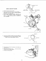
CHECK
MOTOR
ROTATION
1.
The motor must rotate
the 5/8 in. shaft.
CLOCKWISE
2.
MAKE
IS REMOVED
3,
Place the motor
4.
Plug the cord into a prcperly
grounded
outlet
ISee
"Motor
Specifications
and Electrical
Requirements"
Section)
Notice
the rotation
of the shaft, If it is not
turning
CLOCKWISE,
REMOVE
the plug from
the
outlet, and change the rotation
of the motor according
to the instructions
furnished
with the motor,
'SURE
"KEY"
on your
workbench
when viewed from
FROM
SHAFT.
or 3n the floor.
5/8
DIA.
IN.
qON
SHAFT
WARNING: FOR YOUR OWN SAFETY, MAKE SURE
PLUG IS NOT CONNECTED
TO POWER SOURCE
OUTLET WHEN CHANGING MOTOR ROTATION.
16
5. Fromamongthe looseparts,find the following
hardware:
4 Carriage
Bolts,5/16-18x 3/4in.long
4 Hex.Nuts,5/16-18
(approx,
dia.ofhole5/16in.)
4 Lockwashers,
5/16in,External
Type
(approx.
dia.ofhole5/16in.)
6. Place
motoronMOTOR
BASE... insertboltsthrough
holesin base... then throughthemotor.Install
Iockwashers,
andnuts.
7. Positionmotorso thatedgeof MOTORFOOTand
MOTOR
BASEareeven.,,slidemotorallthewayto
theRIGHT,..tightenthefournuts.
8. Loosenset screwin motorpulleyusing5/32 in.
setscrew
wrench.
SlidepulleyonshaftwithHUBaway
frommotor.DONOTTIGHTEN
SETSCREW.
9.
10.
LOCKWASHER
._/16 IN.
5/16-]8
NUT
SHAFT
GUARD
THESE 1WO
EDGES
motor
into
HOLES
and
insert
in cradle
the
...
TWO
PINS
push motor
on motor
CARRIAGE BOLT
5/16-1_ X 3/4 iN.
!}
',i ./
BASE
MOTOR
MOUNTING
BASE
ULLEY
KEY
Install 3/16"
in. square key (furnished
with motor)
in
grooves in pulley and motor shaft. DO NOT TIGHTEN
S ETSC R EW.
Lift
EVEN
base
in as far as it will
go.
11.
Lower
pulley.
the blade..
12.
Sight
along
,install
edges
of
be:t on saw pulley
both
pulleys
arid
and motor
move
motor
pulley
so that belt is parallel
to the edges of both
pulleys..
,tighten the setscrew in the motor pulley.
13.
IMPORTANT:
Measure
the distance
from
shaft to pulley...mark
this dimension
down;
need it later when reinstalling
the pulley.
14.
15.
Make
up.
sure
blade
is g0 ° to table..
EDGE OF WASHE_
EVEN WITH END
OF SLOT
end of motor
you
will
,raise it all the way
CLAMP
Lift motor until edge of washer is even with end of slot
...
tighten
pivot screw. In this position,
pull motor
toward
you (pins will slide out of cradle) until belt is
TIGHT
...
tighten
the two MOTOR
BASE CLAMP
SCREWS.
16.
Loosen
17.
Lower
Pivot Screw
slightly,
the saw blade all the way down.
18. IMPORTANT:
Motor should
blade is lowered.
If it does
SCREW some more.
pivot freely downward
as
not, LOOSEN
the PIVOT
PIVOT
MOTOR
19. Pivot screw must be adjusted only tight enough to allow
motor to pivot FREELY
as blade is raised or lowered.
This will maintain
constant
tension on belt.
PULLEY
CAPACITOR
COVER
20. Loosen
the two MOTOR
CLAMP
SCREWS on each
end
of
motor.
Rotate
the
motor
so that
the
CAPACITOR
COVER
is on top..,
tighten the screws.
The ventilation
holes are now facing downward
which
will help prevent sawdust from entering motor.
VENTILATION
HOLES
17
MOTOR
CLAMP SCREW
(BOTH ENDS)
SCREW
BASE
SCREWS
TWO HOLES CLOSEST
TOGETHER
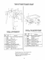
INSTALLING
1.
Remove
2.
Screws furnished
screw
them into
the belt and motor
BRACKET.
3.
Position
BELT
screws
BELT GUARD
then
BELT
/
BELT GUARD
SUPPORT BRACKET
pulley.
%
with guard are "self threading"
holes iN BELT
GUARD
SUPPO'R'T
remove
SCREW
\
BELT GUARD SUPPORT
them
GUARD
SUPPORT
BRACKET
and
GUARD
SUPPORT
as shown
and install
...
make sure motor
shaft is in CENTER
the
of
BELT GUARD
f
hole in SUPPORT.
\
PIVOT
SCREW
!
CENTERED
OPENING
Insta
three CLIPS
/furnished
with guard) 90 ° apart
starting
with one cliD at the end of the guard as shown
•.. LONG END of clip facing AWAY from you.
BELT GUARD
\
LONG
5.
Reinstall
motor
aligned the belt.
pulley
the same way
6.
Place belt on SAW" PULLEY
..
through opening in END of guard.
7.
Silo belt over motor
it was when
insert
end
of
you
belt
pulley•
18
END
8°
Press guard
approximately
onto support
so that bottom
3/4 in. away from beFt°
of
guard
is
NOTE:
To remove guard, lift up on LONG TABS of
clips ...
pull guard outward.
The clips should remain
on the BELT GUARD
SUPPORT.
8/4
i
ASSEMBLING
(Included with
HOLD-DOWN
Model 113.298240)
Locate the clamp assembly, support
and two washers in loose parts bag.
Screw the support
gauge head.
rod (I)
tightly
rod, two
into
wing
screws
the hole in the miter
Position the clamp assembly (2) on the
install washers (3) and wing screws (4).
handle
LATCH
and rod...
CLAMP LOCK
NOTE:
The small knob (5) on the clamp screw must not
turn.
Check nut underneath
it ... it must be tight against
the knob. Use a 1/2 inch wrench to tighten it.
PLUGGING
1
IN MOTOR
1.
From
2.
Route motor cord along right side of cabinet and snap
ties in 1/4" hole in side of cabinet. Secure two cords in
wire ties.
among the loose parts, find
3.
Plug motor
cord
into outlet
two
wire
ties
on side of switch
box.
19
IN.
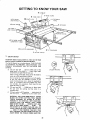
GETTING TO KNOW YOUR SAW
9 SAWBLADE
7
8
MITER
GAUGE
LOCK
HANDLE
6
MITER
|0
BLADE
GUARD
TABLE INSERT
EXACT-I-CUT
ANTIKICKBACK
PAWLS
_
GAUGE
RIP FENCE
RIP FENCE
LOCK HANDLE
4
TILT LOCK HANDLE
(UNDERNEATH TABLE)
2
ELEVATION
HANDWHEEL
3
] ON-OFF
1
TILT
HANDWHEEL
SWITCH
ON-OFF SWITCH
CAUTION:
Before turning switch on, make sure the blade
guard is correctly installed and operating properly.
@
The On-Off Switch has a locking feature. THIS FEATURE
IS INTENDED
TO PREVENT
UNAUTHORIZED
AND
POSSIBLE
HAZARDOUS
USE
BY CHILDREN
AND
OTHERS.
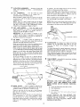
A.
TO
turn
saw
ON
,..
stand
to either
blade never in line with it ...
insert finger
switch lever and pul! END of lever out.
After turning switch ON, always allow
come uo to full speed before cutting.
KEY
side of the
(YELLOW PLASTIC)
under
the blade to
Do not cycle the motor
switch on and off rapidly,
as this may cause the sawblade
to loosen. !n the
event this should ever occur, allow the sawblade to
come to a complete
stop and retighten
the arbor
nut normally,
not excessively.
Never leave the saw
while the power is "'ON".
B.
TO
turn
the saw
complete
C.
saw OFF
until
stop.
TO lock switch
with one han_
the
...
PUSH
cutting
lever in. Never
tool
has
come
KEY
leave
_o
a
in OFF position
... hold switch IN
..
REMOVE
key wtl.h other hand.
WARNING:
FOR YOUR OWN SAFETY, LOWER
BLADE OR OTHER CUTTING TOOL BELOW
TABLE
SURFACE.
(IF BLADE
IS TILTED,
RETURN IT TO VERTICAL
(90 ° ) POSITIONL
ALWAYS
LOCK THE SWITCH "OFF".
WHEN
SAW IS NOT IN USE ... REMOVE KEY AND
KEEP IT IN A SAFE PLACE ... ALSO ... IN
THE EVENT OF A POWER FAILURE (ALL OF
YOUR LIGHTS GO OUT) TURN SWITCH OFF
... LOCK IT AND REMOVE THE KEY. THIS
WILL PREVENT THE SAW FROM STARTING UP
AGAIN WHEN THE POWER COMES BACK ON.
i!!,
2O
2
ELEVATION
blade, Turn
to lower.
HANDWHEEL
. . . elevates or lowers the
clockwise
to elevate ... counterclockwise
TILT
HANDWHEEL
...
tilts
the
cutting.
"_'urn clockwise
to tilt
counterclockwise
to tilt toward
right.
blade
toward
If necessary, the miter gauge head can then
slightly
to compensate
and then locked.
Slots are provided
in the miter gauge for attaching
an
AUXILIARY
FACING
to make it easier to cut long
pieces. Be positive
facing does not interfere
with the
proper operation
of the sawblade guard.
for
bevel
left
...
When the blade is tilted to the LEFT as far as it will go,
it should be at 45 ° to the table and the bevel indicator
should
point
NOTE:
There
Select a suitable piece of smooth straight wood..,
two holes through it and attach it with screws.
TILT
LOCK
are LIMIT
STOPS
inside
the saw which
HANDLE
...
locks
the
blade
in
NOTE:
When bevel crosscutting,
attach facing so that it
extends
to the right of the miter gauge and use the
miter gauge in the groove to the right of the blade.
the
desired tilt position.
To loosen, turn counterclockwise.
Push handie
in and turn
it to another
position
necessary in order to tighten or loosen.
if
IMPORTANT:
Be sure
handle
is hanging
in the
"DOWN"
position
before tilting
blade. If it is pointing
to the 1 o'clock
position
it may jam on underside
of
the table and bend the locking bolt,
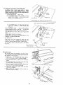
RIP FENCE
...
is locked
in place by tightening
lock knob.
To move the fence, loosen the knob
grasp the fence with one hand at the front.
Holes
facing
STO I
7
Select a piece of smooth
straight
wood approx.
3/4"
thick,
at least as long as the rip fence, and at least
7-1/2"
wide (high) to permit clamping
of featherboards.
it
to
the
fence
with
three
Round
Head
the round
#10
BLADEGUARD
must always be in place and working
properly
for
all thru-sawing
cuts. That
is, all cuts
whereby
the blade
cuts
completely
through
the
workpiece.
the
DO
type cut in material
thinner
fence is positioned
over the
8
depressed area of table extension,
the facing should be
attached to the fence so that the bottom
edge touches
the top surface of the extension.
In this case, the facing
must be shorter than the fence. This will prevent thin
material from sliding under the rip fence.
WOOD
AUXILIARY FAC!NG
When replacing
the guard, make sure the PIN in the rod
engages with the NOTCH in the spreader support.
Make
sure thumbscrew
is tightened
securely.
holes.
If you are making a rip
than 3/16 in. while the
_
To remove the guard for special operations,
loosen
thumbscrew
and slide the guard off of the rod.
NOT DISTURB
THE SETTING
OF THE ROD.
Wood Screws 2 in. long. To remove the facing, loosen
the screws, slide the facing forward
and pull the screws
through
_
the
and
are provided
in the rip fence for attaching
a wood
when using the dado head, or molding head.
Attach
drill
45 ° .
prevent the blade from tilting beyond 45 ° to the LEFT
and 90 ° to the RIGHT.
(See "Adjustments"
section
"Blade Tilt, or Squareness of Blade to Table").
4
be swiveled
TABLE
INSERT
blades or other
is removable
cutting
for removing
or installing
tools.
FACING
SCREW
#I0 WOOD
6
WARNING:
FOR
SWITCH
"OFF"
POWER
SOURCE
INSERT.
SCREWS
MITER
GAUGE
...
head is locked
in position
for
crosscutting
or mitering
by tightening
the lock knob.
ALWAYS
LOOK IT SECURELY
WHEN IN USE.
There
are "_wo slots
left
for
right
_lnd
positions
Miter
Gauge to cut miters.
the
for
stop
pin
conveniently
at the 45 degree
setting
the
A.
Lower the blade below
B.
Raise blade guard.
C.
Loosen
D.
Lift
front
NOTE:
The slots for the stop pin and the graduations
are
manufactured
to very
close
tolerances
which
provide
accuracy
for average woodworking,
in some
cases where extreme
accuracy is required, when making
angle cuts, for example,
make a trial cut and then
recheck it.
YOUR
OWN
SAFETY,
TURN
AND
REMOVE
PLUG
FROM
OUTLET
BEFORE
REMOVING
the table surface.
Screw.
insert
from
front
end,
and
pull
toward
of saw.
NEVER
OPERATE
THE
SAW WITHOUT
THE
PROPER INSERT
IN PLACE.
USE THE SAW BLADE
INSERT
WHEN
SAWING
. . . USE
THE
COMBINATION
DADO
MOLDING
INSERT
WHEN
DADOING
OR MOLDING.
21
9
REMOVING
AND INSTALLING
SAWBLADE.
WARNING:
FOR YOUR OWN SAFETY,
TURN
SWITCH
"OFF"
AND REMOVE
PLUG FROM
POWER SOURCE OUTLET BEFORE REMOVING OR
INSTALLING SAWBLADE.
A Raise Blade Guard...remove
insert.
B. To REMOVE blade, olace a block of wood
against front of blade
.. PULL arbor wrench
toward you to LOOSEN arbor nut.
BLADE
GUARD
BLADE
C.
To TIGHTEN
against rear
from you.
Always
tighten
SHOWN
GUARD
NOT
FOR
SHOWN
PICTURE CLARITY
FOR
side of
the arbor
...
make sure the teeth
of the saw ... and that
and free from any burrs.
the
collar
must
are
the
be against
the
Head, it is not
ARBOR
nsert
ooening
n ............
toward
keyslot
rear of saw _o engage spr ng clip
in insert will arop over screw. Tighten
Do not
tighten
screw
to the
point
where
NUT
LOOSE
COLLAR
and until
screw.
it wil
ARBOR
_
deflect
_,-'_
d_
_'_
FRONT OF SAW
lO
CLARITY
nut securely.
NOTE: When usinc; the Dado or Molding
necessary to install the loose collar.
To replace insert.
Place nsert
into
PICTURE
arbor nut, place a block of wood
of blade
...
PUSH wrench away
When installing
the blade
pointing
toward
the front
blade and collars are clean
The HOLLOW
blade.
NOT
/
\
"_\
_ \
A_.BOR NUT
_
EXACT-I-CUT
The "yellow"
plastic disc imbedded
in the table in front
of the sawblade, is provided for marking the location of
the "'sawcut" on the workpiece.
A.
Check disc
...
if it is above table surface, place
piece of hardwood
on top of it and tap it down.
B
With blade 90 ° (square to table)
wood.
C.
Pull miter gauge back until wood is over disc. Using
very sharp pencil, mark a line on disc.
D.
With miter gauge in right hand groove, follow
procedure and mark another line on disc.
E.
These lines indicate the
made by the sawblade.
F.
When
cutting
workpiece
with
"'path"
the workpiece,
line on disc.
a
cut off a piece of
of the
line
up
cut
same
BLADE GUARD NOT SHOWN FOR PICTURE CLARITY
(kerr)
mark
on
22
BASIC SAW OPERATION
WORK HELPERS
Before
"Basic
Notice
cutting
any wood
Saw Operations".
that
in
order
on
to
your
make
AUXI
saw,
some
study
of
the
all
of the
cuts,
it
NOTE:
is
which
FENCE/WOR
Since
Fence,
necessary
to use certain devices "Work
Helpers"
like the
Push Stick,
the Push Block and the Auxiliary
Fence/Work
Support,
LIARY
K SUPPORT
Make one using a piece of 3/8 in. and 3/4
Fasten together with glue and woodscrews.
both
the
the
Push
4-3/4
Block
in, plywood.
is used with
in. dimensions
must
the
be held
Auxiliary
identical
on
the pieces.
THESE EDGES MUST
BE PARALLEL
you can make yourself.
3/4
PLYWOOD
After you have made a few practice
cuts, make up these
"helpers"
before starting
any projects.
Make the "Push
Stick" first.
PUSH STICK
AND
PUSH
]
BLOCK
Make the Push Stick using a piece of 1 x 2, or rip one from
a wide board, say 11-1/2 in. wide, and set the rip fence
9-7/8 in. from the sawblade.
Make the
plywood.
Push Block
using
a piece
of 3/8
in. and 3/4
318
in.
2-1/2
-F
2q/2
The small piece of wood 3/8 in. x 3/8 in. x 2-1/2 in. should
be GLUED
to the plywood
. .. DO NOT USE NAILS.
This
is to prevent
dulling
the sawblade
in the event
you
mistakingly
cut into the push block.
Position
together
the handle in the center of the plywood
with glue and woodscrews.
PUSH BLOCK
3/8
3/8
_"_
NOTE: All dimensions in inches
3/8 PLYWOOD
and fasten
3,/4 PLYWOOD
15
45° NOTCH
WORKPIECE
I/4
THIS FACE AND
THiS
_"
30
EDGE .MUST BE PARALLEL
PUSH
NOTE:
END
1//4
All dimensions
STICK
AUXILIARY
FENCE/
WORK SUPPORT
in inches
3/8 PLYWOOD
_l
NOTE: All dimensions in inches
USING
THE
MITER
6.
CROSSCUTTING,
MITER
CUTTING,
BEVEL
CUTTING,
COMPOUND
MITER
CUTTING,
DADOING
and when
RABBETTING
AND MOLDING
across the end of a narrow
workpiece,
THE
MITER
GAUGE
WARNING:
FOR
YOUR
OWN
SAFETY,
ALWAYS
OBSERVE
THE FOLLOWING
SAFETY
PRECAUTIONS
IN ADDITION
TO THE SAFETY
INSTRUCTIONS
ON
PAGES
1.
using
the
miter
gauge or other
auxiliary
devices)
because
blade could bind in the cut and cause a KICKBACK
make
the
or
cause your
lock
these
fingers
cuts
freehand
(without
Always
3.
Remove
4.
Make sure blade guard is installed
for all "thru,sawin9
_,
operations
(when
sawblade
cuts
entirely
thru
the
thickness
of
the
workpiece.)
Replace
guard
IMMEDIATELY
after completion
of dadoing,
molding
the miter
rip fence from
or rabbeting
5,
Keep your hands clear of the blade and out of the path
of the blade.
8.
If blade stalls or stops while cutting,
TURN
OFF before attempting
to free the blade.
9.
Do
gauge securely
when
reach
over
or
behind
the
blade
to
pull
the
or
of
10. Do not pick up small pieces of cut-off
material from the
table. REMOVE
them by pushing them OFF the table
with along stick. Otherwise
they could be thrown back
in use.
table.
at you by the rear of the blade.
11. Do not remove small pieces of cut-off
material that may
become TRAPPED
inside the blade guard while the saw
is RUNNING.
THIS
COULD
ENDANGER
YOUR
HANDS
or cause a KICKBACK.
cuts.
Have blade extend approximately
1/8
workpiece.
Additional
blade exposure
the hazard potential,
not
SWITCH
workpiece
through
the cut
...
to support
long
heavy
workpieces
...
to remove
cut-off
pieces
material or FOR ANY OTHER
REASON.
or hand to slip into the blade.
2.
side of the blade.
7.
2, 3, and 4.
Never
GAUGE
Do not stand directly
in front of the blade in case of a
THROWBACK
(Small cut-off
piece caught by the back
of the blade and thrown
toward the operator).
Stand to
either
IS USED.
5-_/2
q
in. above top of
would
increase
Turn
lift
23
the saw OFF.
the guard
After
and remove
the blade has stopped
the piece.
turning,
CROSSCUTTING
CROSSCUTTING
the grain, at 90 °,
side of the wood.
is known
as cutting
wood
across
or square with both the edge and the flat
This is done with miter gauge set at "'0".
The graduations
on the miter gauge provide
accuracy
for
average
woodworking.
In some
cases where
extreme
accuracy
is required,
when making angle cuts, for example,
make a trial
cut and then recheck
it with
an accurate
square, or protractor.
If necessary, the miter gauge head can be swiveled
to compensate
for any inacurracy.
NOTE:
The
space
groove
in
the
manufacturing.
between
table
is
the
held
miter
to
gauge
a
slightly
bar and
minimum
the
during
For maximum
accuracy when using the miter gauge, always
"favor"
one side of the groove in the table. In other words,
don't move the miter gauge from side to side while cutting,
but keep one side of the bar riding against one side of the
groove.
The miter gauge may be used in either
table. Make sure it is locked.
NOTE: Glue a piece of sandpaper
to the face of the miter
gauge head. This wil
help prevent
the workpiece
from
"creeping"
while it is being cu_.
When using the miter gauge in the LEFT hand groove, hold
the workpiece
firmly
against the miter
gauge head with
your left hand, and grip the lock handle with your right.
The Hold-Down
Clamp (Optional
Accessory)
included with
113.298240
should be used on the miter gauge for greater
accuracy.
When using the
with
your right
hand.
RIGHT
Hand groove, hold the workpiece
hand and the Iockhandle
with your left
\
When
cutting
tong
workpieces,
invert
AUXILIARY
FENCE/WORK
SUPPORT
and position
it on
guide bars to support
the workpiece
as near to
possible. If this does not adequately
support the
you can make a simple
support
by clamping
plywood
to a sawhorse.
top of the
the end as
workpiece,
a piece of
Use the Hold-Down
Clamp (Optional
Accessory)
with
113.298240
on the miter gauge for greater
included
accuracy.
REPETITIVE
of the grooves in the
\
AUXILIARY FENCE/
WORK SUPPORT
CUTTING
REPETITIVE
CUTTING
is known as cutting
a quantity
of
pieces the same length without
having to mark each piece.
1.
Use the Stop Rods (optional
accessory)
duplicate
pieces 6 in. long and longer.
2.
DO NOT FEED
guide it, making
sawblade.
only
for cutting
workpiece
with RIGHT
Hand, merely
sure that it does not bind or pinch the
When making repetitive
cuts from
sure t is adequately
supported.
a long workplece,
Use the Hold-Down
Clamp (Optional
Accessory)
with
113.298240
on the miter gauge for greater
make
included
accuracy.
AUXILIARY
FENCE/
WORK SUPPORT
24
1.
NEVER
USE" THE RIP FENCE AS A LENGTH
S',v,
BECAUSE
THE
CUTOFF
PIECE
COULD
BIND
BETWEEN
THE FENCE AND THE BLADE
CAUSING
A KICKBACK.
2•
When making repetitive
cuts shorter than 6 in., clamp a
block of wood 2 in. long to the table to act as a length
stop. Do not clamp directly
to the bottom
edge of the
table because the "swivel"
of the clamp will not grip
properly.
Place a _mall block of wood
between
the
bottom
edge of the table and the "C" clamp.
CAUTION:
When clamping the block, make sure that
the end of the block is well in front of the sawblade. Be
sure it is clamped securely.
3.
Slide the workpiece
along the miter
gauge until
it
touches the block ... hold it securely or clamp it with
the Hold-Down
Clamp (Optional
Accessory)
included
with 113,298240.
4.
Make the cut ... pull the workpiece
back..,
push the
cut off piece off the table with a long push stick...
DO
NOT ATTEIVlPT
TO PICK
IT UP AS THIS COULD
ENDANGER'.
YOUR HANDS.
MITER
MITER
CUTTING
CUTTING
is known
as cutting
wood
other than 90 ° with the edge of the wood.
procedure as you would for crosscutting.
Adjust
the miter
The miter
table.
CUT OFF
PIECE
gauge to the desired
at an angle
Follow
the same
angle, and lock it•
gauge may be used in either
of the grooves
in the
When using the miter gauge in the LEFT Hand groove,
the workpiece
firmly
against the miter gauge head
your left hand, and grip the lock knob with your right.
hold
with
When using the RIGHT
hand groove,
hold the workpiece
with your right hand and the knob with your left hand.
Use the Hold-Down
Clamp
(Optional
Accessory)
included
with
Model
113.298240
on the miter gauge for greater
accuracy.
BEVEL
BEVEL
CROSSCUTTING
CROSSCUTTING
is the
same
as crosscutting
except that the wood is also cut at an angle
90 ° with the flat side of the wood.
Adjust
the blade to the desired
. • • other
than
angle.
Use the Miter Gauge in the groove to the RIGHT
of the
blade. It cannot
he used in the groove to the LEFT because
the blade guard will
interfere.
Hold
the workpiece
with
your right hand and the Iockhandle
with your left hand.
Use
the
additional
AUXILIARY
FENCE/WORK
support of the workpiece.
SUPPORT
Lay it across the guide bars to support
near to the end as possible•
the workpiece
for
as
Use the Hold-Down
Clamp
(Optional
Accessory)
included
with
Model
113.298240
on the miter gauge for greater
accuracy.
COMPOUND
COMPOUND
MITER
MITI::R
CUTTING
CUTTING
is a combination
of miter
cutting and bevel crosscutting. The cut is made at an angle
other than 90 ° to both the edge and the flat side of the
wood.
Adjust
the mi_er gauge and the blade
•.. Make sure miter gauge is locked.
to the desired
angle
25
USING THE HOLD-DOWN
When cutting
wide
pieces of material,
move the clamp
assembly forward
as far as it will go...
grip the lock handle
and tighten
by turning
clockwise
until
lock
handle
is
secured. Tighten
both wing screws.
When cutting
narrow
pieces of material,
adjust the clamp
assembly with the clamp over the center of the workpiece.
Grip the lock handle and tighten
by turning clockwise
until
lock handle is secured. Tighten
both wing screws,
The clamp
screw contains
a "rapid
approach"
feature.
Disengage
clamp
lock
latch,
press
IN the
r_pid
approach
button
which
is located
on the left side of the clamp
assembly
and PUSH DOWN
or PULL
UP on the clamp
screw. Release button
and tighten
the clamp screw. Engage
clamp lock latch.
FOR YOUR PROTECTION,
NEVER
USE MITER
WITH CLAMP LOCK LATCH
DISENGAGED.
GAUGE
\
SUPPORT
LONG
WORKPIECES
...
s_mple support
bv clamping
a p_ece
sawhorse,
you
can make
o]' plywood
to
a
a
ADD
FACING
to front
face of miter gauge head for
support as needed. It must not extend past the right end including
the 45 ° corner
of miter gauge head when miter
gauge is used in the left table groove, nor east the left end
when
mi_er
gauge
is usea
Otherwise,
the FACING
will
guard
and prevent
proper
in the
interfere
right
with
table
groove,
the saw blade
and safe operation.
CAUTION:
For bevel crosscutting
or compound
miter
cutting, use the miter gauge in the groove to the RIGHT of
the blade
.. NEVER
TO THE LEFT. This will permit the
guard and the miter gauge to function
properly.
Always
disengage
approach
release
clamping
clamp
button.
lock
knob
-- unclamp
latch
before
End of work_)iece must extend
side of shoe of clamo screw.
workpiece
pressing
at least two
in
and
\
rapid
inches to either
\
\
\
\
\
Wiae (12"' or wider_ and long (2 feet or longer) pieces of
plywood,
chip board or wall paneling should be cut using
the rip fence rather than the miter gauge.
NOTE:
It may be necessary to add a facing to the Fence to
prevent
very thin materials
like wall paneling
or formica
from slipping under the fence. Support wide workpieces
to
the rear of the table -- you e_n make _ _=rn_le cup5ort
by
clamping
a piece of plywood
to a sawhorse.
BE POSITIVE
edge of workpiece
next to
gauge head is straight
and tight against miter
that workpiece
does not rock or rotate,
When
repositioning
Head
necessary
to loosen
both
lessening the Lock Handle.
face of miter
gauge head so
to another
miter
angle, it is
Wing Screws slightly
before
CAUTION:
After setting angle, secure Lock Handle
both Wing Screws, in that order, before clamping
workpiece and engaging the clamp lock latch.
workpiece
thru the sawblade. For narrow work, place other
hand so thumb
is hooked
behind
miter gauge head and
fingers hooked over leading edge for work. For wider work
and
the
where other hand cannot span board as aoove, ptace hand
on top of work and hook fingers over leading edge of work
to hold it tight against the face of the miter gauge during
the cutting operation.
ALWAYS
use both hands when operating
with miter gauge.
Place one hand on the lock handle -- use this hand to feed
Never use mter
26
gauge with
clamp
lock
latch
disengaged.
USING
THE
RIPPING, BEVEL RIPPING, PLOUGHING,
MOLDING,
RESAWING ANO RABBETING are performed using the
RIP
FENCE
together
with
the
AUXILIARY
FENCE/WORK
SUPPORT, PUSH STICK OR PUSH
BLOCK.
WARNING:
FOR YOUR OWN SAFETY,
ALWAYS
OBSERVE THE FOLLOWING SAFETY PRECAUTIONS
IN ADDITION
"ro THE SAFETY INSTRUCTIONS
ON
PAGES 2, 3, and 4.
Never
make these cuts
FREEHAND
rip fence or auxiliary
devices
the
blade
could
bind
in
KICKBACK.
(without
using the
when required)
the
cut
and
lock the rip fence securely
Always
3.
Remove
4.
Make sure blade guard is installed
for all thru-sawing
type cuts. Replace the guard IMMEDIATELY
following
completion
of resawing, rabbeting,
dadoing, or molding
operations.
gauge from
when
Pull
while
5.
Have blade extend approximately
1/8
workpiece.
Additional
blade exposure
the hazard potential.
6.
Do not stand directly
in front of the blade in case of a
KICKBACK.
Stand to either side of the blade.
7.
Keep your hands clear of the blade and out
of the blade.
8.
If the blade
SWITCH OFF
9.
in use.
table.
Frequently
clheck the action of the
PAWLS
by passing the workpiece
spreader
not DIG into the workpiece
and HOLD it...
the pawls
must be SHARPENED.
See "Maintenance"
section.
because
cause
a
2.
miter
RIP FENCE
ANTIKICKBACK
alongside
of
the
you.
If the
do
PAWLS
Position
the
starting
WIDTH
OF
the
RIP and lock
to rip, be sure
A.
Rip Fence is parallel
to sawblade.
B.
Spreader
aliqned
C.
Antikickback
is properly
When ripping LONG
use a work support.
A simple one can be made
to a sawhorse.
BEVEL
When bevel
ripping
with
pawls are functioning
BOARDS
material
or LARGE
by clamping
sawblade.
properly.
PANELS,
always
a piece of plywood
RIPPING
6 in. or narrower,
use fence on
the right side o_ the blade ONLY.
This ,will provide
more
space between the fence and the sawblade for use of a push
stick.
If the fence is mounted
to the left, the sawblade
guard
may interfere
with
proper
or behind
the
use of a push stick.
When "WIDTH
OF RIP" is 6 in.
RIGHT
Hand to feed the workpiece
table.
and WIDER
use your
until it is clear of the
Use LEFT hand ONLY to guide the workpiece
FEED the workpiece
with the left hand.
...
blade
to
pull
the
long or
pieces of
10. Do not pick up small pieces of cut-off
material
table.
REMOVE
them by pushing them OFF
from the
the table
lift
in place.
Before
over
the saw OFF.
the guard
After
and remove
ALWAYS
as cutting
a piece of wood with
This is done using the rip fence.
fence to the desired
while
cutting.
TURN
to free the blade.
could
be thrown
back
11. Do not remove small pieces of cut-off
material that may
become TRAPPED
inside the blade guard while the saw
is RUNNING.
THIS
COULD
ENDANGER
YOUR
HANDS or cause a KICKBACK.
RIPPING
RIPPING
is known
grain, or lengthwise.
reach
or stops
attempting
workpiece
through
the cut
...
to support
heavy workpieces
.... to remove small cut-off
material or FOR ANY OTHER
REASON.
Turn
TOWARD
not
of the path
stalls
before
with a long stick. Otherwise they
at you by the rear of the blade.
saw is OFF.
the workpiece
Do
in. above top of
would
increase
do not
27
the blade has stopped
turning,
the piece.
SUPPORT
LONG
WORKPIECES
When
PUSH
"WIDTH
OF RIP"
is 2 in.
STICK to feed the work.
to 6 in. wide
USE THE
When WIDTH
OF RIP is NARROWER
than 2 in,, the push
stick CANNOT
be used 10ecause the guard will interfere...
USE
the AUXILIARY
FENCE/WORK
SUPPORT
ane
PUSH BLOCK.
Attach
Auxiliary
two "'C'" clam _s.
Fence/Work
Support
to
rip
fence
with
\
Feed the workpiece
by hand
along
the AUXILIARY
FENCE until the end s approx.
1 n. oast the front edge of
the table. Continue
[o feed using the PUSH BLOCK.
Hold
the worKpiece
in
BLOCK
by
sliding
it
FENCE/WORK
SUPPORT
oosition
and install
the PUSH
on top
of
the AUXILIARY
(This May Raise Guard)
BAFFLE
/
Narrow
strips
thicker
than
the Auxiliary
Fence?Work
Support
may
enter
the
gJard
and strike
the baffle.
CAREFULLY
raise guard
only
enough
to clear
the
workoiece.
Use PUSH BLOCK to complete
cut.
28
PLOUGHING
AND
MOLDING
MOLDING
is shaping the workpiece
with the grain the long
way
of the workpiece,
using
the fence.
Use proper
holddowns
and feed devices,
PLOUGHING
is grooving with the grain the long way of the
workpiece,
using the fence.
USE proper
holddowns
and
feed devices.
RESAWING
RESAWlNG
is known
as ripping
a piece of wood through
its thickness.
Do not
attempt
to resaw
BOWED
or
WARPED
material.
NOTE:
To RESAW a piece of wood
wider than 3-3/8 in ....
it will be necessary to remove the
blade guard ... and use the AUXILIARY
FENCE/WORK
SUPPORT.
(See "Work
Helpers").
Clamp it to the table so that the workpiece
will SLIDE
EASILY
but not TILT
or MOVE
SIDEWAYS
without
BINDING
between the two fences.
SMALL BLOCK
OF WOOD
Do not clamp directly
to the bottom
edge of the table
because the "swivel"
of the clamp will not grip properly.
Place a small block
of wood between
the bottom
edge of
the table and the "C"
WARNING:
1.
FOR
2. MAKE FIRST PASS TO A DEPTH SLIGHTLY LESS
THAN ONE-HALF THE WIDTH OF THE BOARD;
KEEP SAME FACE OF BOARD AGAINST
FENCE
FOR SECOND PASS AS THE FIRST PASS.
3. INSTALL
BLADE GUARD IMMEDIATELY
UPON
COMPLETION
OF THE RESAWlNG OPERATION.
clamp.
YOUR
OWN SAFETY
...
DO NOT "BACK
UP" (REVERSE
FEEDING)
WHILE
RESAWlNG
BECAUSE
THIS
COULD
CAUSE
A
KICKBACK.
CUTTING
AUXILIARY
FENCE/
WORK
SUPPORT
PANELS
When cutting
panels (whenever
fence is positioned
odtside
of
table
surface);
ALWAYS
use the
AUXILIARY
FENCE/WORK
SUPPORT.
1.
Unlock
2.
Position
AUXILIARY
FENCE/WORK
SUPPORT
shown and attach it with two "C" clamps.
fence and raise rear end.
as
RABBETING
Rabbeting
is known
of a piece of material,
as cutting
out a section of the corner
across an end or along an edge.
To make a RABBET
requires cuts which
way through
the materiaL. Therefore
the
be removed.
do not go all the
blade guard must
1:
Remove
2.
For rabbetilag along an edge (long way of workpiece)
as
shown, add facing to rip fence (see 5. RIP FENCE, p.
21) approximately
as high as the workpiece
is wide.
Adjust
rip fence and blade to required dimensions;
then
make first cut with board flat on table as any rip (type)
cut; make second cut with workpiece
on edge. Follow
all precautions,
safety
instructions,
and operational
instructions
as for
ripping,
or rip type
operations,
including
feather boards and push stick, etc.
3.
For
blade guard.
rabbeting
across an end, for
workpiece
narrower
make the rabbet cut with the board flat on
the table using the miter gage fitted
with a facing (per
"6. MITER
GAUGE"
on p.21).
DO NOT use the rip
fence.
4.
101/2" and
29
INSTALL
BLADE
GUARD
IMMEDIATELY
COMPLETION
OF RABBETING
OPERATION.
Rabbet
cuts
molding
head.
can
also
be made
using
the
dado
UPON
head
or
DADOING
Instructions
for operating
the Dado Head are contained
booklet furnished
with the Dado Head
The
Recommended
Dado
Head
is
Recommended
Accessories in this manual.
Th_ arbor
on
widest cut that
listed
the saw, is omy
long enough
can be mace is 13/16"
wide.
It is not
necessary
screwing
on the arbor
ALWAYS
USE
RECOMMENDED
to
install
nut.
the outside
loose collar
DADO
INSERT
ACCESSORIES.
TABLE
DADO
NSERT
/
under
so that
Make sure the arbor
SAW
iP
the
before
nut is tight.
LISTED
UNDER
When using .the dado head it will be necessary to remove
[he Blade
Guard
and Spreader.
USE CAUTION.
USE
FEATHERBOARDS
AND PUSH STICKS AS REQUIRED.
ALWAYS
SPREADER
REPLACE
WHEN YOU
MOLDING
THE
BLADE,
ARE FINISHED
GUARD
DADOING.
@
CUTTING
Instructions
in a booklet
for operating
the Molding
furnished
with the Molding
Always
use
Accessories.
Molding
Insert
When using the molding
the Blade
Guard
aria
FEATHERBOARDS
REQUIRED.
Head are contained
Head.
The
recommended
molding
head
Recommended
Accessories in this manual.
USING
AND
is
listed
under
Listed
Under
Recommended
board
to
fence,
ALWAYS
SPREADER
THE
BLADE
ARE FINISHED
GUARD
MOLDING.
AND
FEATHERBOARDS
Add
8 inch high flat
length of the fence,
facing
the
the
full
Before
starting
the
below table surface):
Use featherboards
for
all non "thru-sawing"
operations
(when sawblade guard must be removed).
Featherboards
are
used to keep the work in contact with the fence and table
as shown, and to stop kickbacks.
Mount
leading
REPLACE
WHEF, YOU
head it will be necessary to remove
Spreader.
USE CAUTION.
USE
AND
PUSH
STICKS,
etc.
AS
featherboards
to fence
edges of featherboards
(a) Install
featherboards
workpiece;
be oositive
and table as shown, so that
will support
workpiece
until
"c"
CLAMPS
Replace the sawblade
operation
is complete.
CLAMPS
CLAMPS
SUPPORT
3O
'OFF'
featherboards
Featherboards
are not employed
during
operations
when using the miter gage.
FEATHERBOARD
"C
WORK
{switch
and
so they
exert
oressure
they are secure, and
(b) Make sure by trial that the
kickback
if one should occur.
cut is complete,
and the workpiece
has been pushed
completely
past the cutter (sawblade,
dado head, molding
head, etc.) with a pushstick,
as n ripping.
C
operation
non
will
cutter
on
the
stop
thru-sawing
guard as soon as the non thru-sawing
a
ADJUSTMENTS
LOCK KNOB
WARNING:
FOR YOUR OWN SAFETY, TURN SWITCH
"OFF"
AND REMOVE PLUG FROM POWER SOURCE
OUTLET BEFORE MAKING ANY ADJUSTMENTS.
MITER
"0"
BAR
GAUGE
NOTE:
The slots for the stop pin and the graduations
are
manufactured
1:o very
close
tolerances
which
provide
accuracy
for average woodworking.
In some cases where
extreme
accuracy is required,
when making angle cuts, for
example,
make a trial cut and then recheck it.
If necessary, the miter gauge head can be swiveled
to compensate
for any inaccuracy.
the "knob"
1.
Loosen
2.
Swivel the head ...
position
it at "'0""
stop pin IN . .. lock the handle.
3.
The HEAD
should
be square
pointer
should
point
to "'0".
necessary.
4.
If the head is not
required.
and pull
"stop
square with
pin"
...
1BLOCK
push the
I
with
the Bar and the
Readjust the pointer
if
the
bar, adjustments
(1) and the "two
screws"
are
Loosen the "knob"
Position the HEAD square with the BAR using a
combination
square.
PUSH the STOP PIN into the slot in the head at
(2)
"0" ... push the pin into the slot and twist
the knob.
Recheck with the square.
If the head is still
square,
loosen the screws
(2) and readjust
INDICATOR
BLOCK.
E.
With the head square with the bar
pushed into the slot adjust the pointer
to "0".
F.
The miter gauge head must rest on top
without
being able to move up and down
must swivel freely.
swiveling
movement
of
the
i
it. Lock
D.
The
I NDI CATOR
OUT.
B.
G.
SQUARE
slightly
A.
C.
II / STOP
not
the
1/8 IN. SETSCREW
WRENCH
and the pin
(3) to point
adjusted by tightening
or loosening the setscrew
•.. using the 1/8 in. setscrew wrench.
of the bar
... yet it
head
can
NOTE:
To reach
the miter
be
The
setscrew
is located
inside
of the head.
it, swivel the head to 60 degrees and turn
gauge upside down.
HEELING ADJUSTMENT
or PARALLELISM
OF SAWBLADE TO MITER GAUGE GROOVE
While cutting,
the material
must
PARALLEL
to the SAWBLADE
move in a straight
...
therefore
both
miter
gauge GROOVE
and the
PARALLEL
to the SAWBLADE.
RIP
FENCE
line
the
must
be
If the sawbladc
IS NOT parallel to the miter gauge groove,
the blade will bind at one end of the cut. (This is known as
"HEELING").
MARK
To check for parallelism:
WARNING
-- FOR YOUR OWN SAFETY,
TURN
"OFF"
AND
REMOVE
PLUG
FROM POWER
OUTLET.
SWITCH
SOURCE
I.
Raise blade all the way up...
2.
Mark an "×'"
the LEFT.
raise blade guard.
3.
Place
the
head of a combination
square
in the
GROOVE
...
adjust blade of square _o that it just
touches the tip of of the MARKED
tooth,
4.
Move square to REAR,
rotate blade to see if MARKED
tooth again touches blade of square.
5.
If tooth
sawblade
on one of the teeth
which
is SET
touches
square at FRONT
and
is PARALLEL
to MITER
GAUGE
(bent)
to
REAR
,..
GROOVE.
31
(4)
"X"
ON
TOOTH
If
tooth
does
not
touch
the
same
amount
mechanism
underneath
must be adjusted
blade PARALLEL
to GROOVE.
trunnion
must
the
the
FRONT
Rear
B.
combination
square
if there
is a space between
marked tooth and end of square in step 4.
Rear trunnion
must
be moved AWAY
from the
if
position
in the groove.
marked
tooth
moved
...
make
A.
square
be
to
pushes
TOWARD
square
REAR TRUNNION
TRUNNION
the
out
of
REAR-TRUNNION
SCREWS
7.
Loosen all three screws that hold the rear trunnion
all three screws that hold the front trunnion.
and
NOTE:
All six screws can be reached through back of saw.
Use a 9/16-in.
wrench.
To reach left-hand
front
trunnion
screw, tilt blade
blade at g0 °.
to 45 °. After
loosening
screws
reposition
LEFT-HAND
RIGHT-HAND
/
CENTER
(BEHIND HERE)
(BEHIND HERE}
i
FRONT-'rRUNNIO
",,
N SCREWS
EDGE
oFTRUNNIOn
CLAW
8.
HAMMER
BLOCK
Using a wood block
and mallet as shown,
move rear
trunnion
to right or left as reauired to realign the blade.
f necessary, shift front trunnion
in similar manner
but
do NOT move front trunnion
unless necessary. Recheck
the alignment
with
the square, then securely retighten
all six trunnion
screws.
PLACE BLOCK HERE
--
BLADE TILT, OR SQUARENESS
OF BLADE TO TABLE
90 ° (SQUARE)
and 45 ° (BEVEL)
When the bevel pointer
is pointing
on the bevel scale, the sawblade
cut 90 ° to the table.
STOP COLLARS.
directly
to the "'O" mark
should make a SQUARE
To check for SQUARENESS:
WARNING:
FOR YOUR
"OFF"
AND
REMOVE
OUTLET.
OWN
PLUG
UP...
SAFETY,
TURN
FROM POWER
SWITCH
SOURCE
1.
Raise blade all the way
2.
Place the souare against blade. Make sure square
touching
the TIP of one of the saw TEETH.
raise blade guard.
is not
32
OR
HERE
;tEAR OF
SAW
EDGE OF
CRADLE
I
3.
Operate
the tilt lock handle (COUNTERCLOCKWISE)
to loosen the tilt clamp screw.
4.
NOTE:
Handle is spring loaded for engagement
with
screw head -. must be pushed inward for disengagement
whenever
necessary to obtain a new grip on screw head.
5.
"1
Rotate tilt handwheel
CLOCKWISE
a few turns to tilt
blade. Now rotate handwheel
COUNTERCLOCKWISE
until it stops. Blade should now
and pointer should point to "0".
be square
with
table
TILT
I
If blade is SQUARE
A.
Check
to table;
TILT,/POINI"-ER_"
POINTER
peinter
IF POINTER
DOES
NOT
point
to
the
"O"
mark
on the
bevel scale;
A.
Remove
Elevation
B.
Loosen screw
screwdriver.
C.
Install
Elevation
\
Handwheel.
and adjust
pointer
...
using
I./
medium
Handwheel.
If blade is NOT SQUARE
must be ADJUS-]-ED.
1.
HANDWHEEL
the 90 ° LIMIT
Using
a medium
size screwdriver,
setscrews in 90 ° STOP COLLAR.
loosen
NOTE:
If you
HANDWHEEL
turn
the setscrews,
BOTH
the TILT
45 ° STOP COLLAR
ROTATE
the STOP COLLAR
moving it all the way to
the end of T!LT SCREW. (to the right}.
3.
TILT
4.
square until blade is square to table.
ROTATE
STOP COLLAR
moving it to the right
5.
stops...
Check
RIGHT
TIGHTEN
POINTER.
or
If
LEFT
...
the setscrews.
it DOES NOT
checking
point
with
to
4
your
until
the
it
"'0""
TILT
HANDWHEEL
mark on the bevel scale...
A.
Remove
B.
Loosen screw
screwdriver.
Elevation
C.
Install
Elevation
Handwheel.
and adjust
SCALE ADJUSTING
SCREW
STOP
2.
blade
'
_OI NTER AT
"0" POSITION
to table..,
can't reach
slightly.
i
pointer
...
using
medium
Handwheel.
33
STOP COLLAR
45 ° POSITI
ON
TILT blade to LEFT as far as it will go. It will stop when
the PIVOT NUT is against the 45 ° STOP COLLAR.
A.
Place an ACCURATE
square against blade. Make
sure square is not touching the TIP of one of the
saw TEETH.
If blade is 45 ° to table:
A.
Check
pointer.
If POINTER
scale;
DOES
NOT
!_oint to the
A.
Remove
B.
Loosen two screws on scale and
POINTER
points to 45 ° mark.
Elevation
C.
Install
Elevation
45 °
mark
on
the
Handwheel.
adjust
scale until
Handwheel.
If blade is NOT 45 ° to table ..
and SCALE must be ADJUSTED.
Elevation
the 45 ° STOP COLLAR
1.
Remove
2.
Handwheel.
Using a small size screwdriver,
reach thru curved
slot in front trim panel and loosen BOTH setscrews
in 45 ° STOP COLLAR.
NOTE:
If you can't
TILT HANDWHEEL
reach the
slightly.
setscrews,
turn
the
3.
ROTATE
the STOP COLLAR
moving it IN or OUT
and TILT
blade RIGHT or LEFT...
checking with
your square until blade is 45 ° to table.
4.
TIGHTEN
the setscrews.
NOTE:
If you
HANDWHEEL
can't reach the setscrews,
slightly.
5.
Loosen two screws on scale and adjust
POINTER
points to 45 ° mark.
6.
Install
Elevation
turn
TILT
scale until
Handwheel.
TI LT MECHANISM
The handwheel
should
turn freely
without
turning
action can be adjusted
by tightening
the screws in the bearing retainer.
TILT
HANDWHEEL
binding.
The
or loosening
NOTE:
Tilt Nandwh_l
mu_t b_ r_n_oved to adjust. When
adjusting
the screws in the bearing retainer,
hold the nut
nside using a 3/8 in. wrench
/
34
ADJUST THESE
. TWO SCREWS
/
I L/j
l'/
MAINTENANCE
WARNING: FOR YOUR OWN SAFETY, TURN SWITCH
"OFF"
AND RIEMOVE PLUG FROM POWER SOURCE
OUTLET BEFORE MAINTAINING
OR LUBRICATING
YOUR SAW.
2.
Rotate
pawl toward
rear of
above top of spreader.
3.
Hold spreader
of workbench.
Do not allow sawdust to accumulate inside the saw.
4.
Using
teeth.
Frequently blow. out any dust that may accumulate inside
the saw cabinet and the motor.
with
a small
s_'e_del_rthat
teeth
are
left hand and place pawl over corner
round
file
(Smooth
Cut)
sharpen
the
Frequently clean your cutting tools with Craftsman Gum
and Pitch Remover,
A coat of automobile4ype
wax applied to the table will
help to keep the surface clean and allow workpieces
to slide
more freely.
If the power cord is worn or cut, or damaged in any way,
have it replaced immediately.
Make
sure
the
always sharp.
1.
Remove
teeth
of
the
ANTIKICKBACK
pawls
are
To sharpen:
blade guard,
LUBRICATION
The following
parts should be oiled
No. 20 or No. 3Q engine oil.
occasionally
1.
Tilt
screw threads
and Divot nut.
Craftsman
Gum & Pitch Remover.)
2
Elevation
Craftsman
3.
Cradle
4.
Bearing
fence.
(First
screw threads and pivot nut.
G Jm & Pitch Remover.)
bearing
(First
with
SAE
Clean
with
Clean with
points.
points
n guard assembly,
miter
gauge and
rip
MITER 3UAGE
'_
BEARING
POINTS
I|
RECOMMENDED
ITEM
Steel
CAT.
Legs
...............................
Steel Stand
Caster Sets
Solid
Table
ITEM
Work
.9-22214
.....................
Extension
9-22222
......................
CAT.
Light
or 9-22221
9-29957
Sanding
Wheel
7 In. Molding
Head Set
......................
9-3217
7 In. Molding
Head Set
......................
9-3218
Miter-Gauge
7 In. Molding
Head
9-3214
Taper
Molding/Dado
or Dado
Work
...............................
Light
Sawdust
Colle('tion
Head
System
Jig
Universal
Insert for 7 In.
Dia. Molding
. ................
Power
9-29997
Table
9-2480
..................
...............................
...........................
Stop
Hold-Down
Jig
Tool
Saw
35
How
9-22723
9-20924
Clamp
9-29928
..............................
Know
9-3262-9-3263
9-3257
.....................
.................................
..............
9-3233
9-3235
Handbook
..............................
1g-Inch
Diameter
with 5/8"
Bore
9-29966
Rods
NO.
9-2481
7 In. Dia. Adjustable
Dado Head
9-3261,7 In. Dia. Dada Head
.......................
Miter-Gauge
.........................
IIIIII
ACCESSORIES
NO.
9-22235
.............................
I
Sawblades
.......................
9-2918
See Catalog
TROUBLE
WARNING:
FOR YOUR OWN SAFETY,
OUTLET
BEFORE
TROUBLESHOOTING.
TURN
SWITCH
TROUBLE
TROUBLE
"OFF"
AND
SHOOTING
PROBABLE
Excessivevibration.
SHOOTING
ALWAYS
REMOVE
PLUG
POWER
-- GENERAL
CAUSE
REMEDY
1. Blade out of balance.
1. Discard
Blade and use a different
2. Damaged
2. Replace
as Indicated.
V-Belt
FROM
Pulleys
blade.
or poor belt.
Cannot
make square
I. Miter
Cut when crosscutting.
Cut binds, burns or
stalls motor
gauge not adjusted
1. Dull blade with
when
tooth
ripping.
1. See "Adjustments"
section
"Miter
Gauge."
properly.
improper
1,
Sharpen
or replace
blade.
set.
2. Blade is Heeling.
2. See "Adjustments"
section,
3. Warped
3. Make sure concave
or hollow
board.
"down,"
4. Rip fence,not
parallel
"Heeling
Adjustment.
side is facing
feed slowly.
4. See "Assembly"
section,
"Aligning
5. See "Assembly"
section,
"Installing
Rip Fence"
to blade.
5. Spreader
out of
alignment
Cut not true at 90 °
Blade
1. Stop collars
or 45 ° positions.
not properly
1. See "Adjustments"
adjusted.
Tilt and elevating
handwbeel turn hard.
1. Sawdust
Guard."
"Squareness
on threads
screw or elevating
of tilt
1. See "'Maintenance
"Blade
Tilt,
or
to Table."
and Lubrication"
section.
screw.
2. Bearing retainers
2. See "Maintenance"
to tight.
TROUBLE
section,
of Blade
"Tilt
SHOOTING
section
and Elevation
Mechanism.'"
-- MOTOR
NOTE: Motors used on wood-working tools are particularly
susceptible to the accumulation of sawdust and wood chips
and should be blown out or "vacuumed"
frequently to
prevent interference with normal motor ventil ation.
TROUBLE
PROBABLE CAUSE
Excessive noise.
1. Motor.
Motor
1. Circuit
full
fails to develop
power.
NOTE:
LOW VOLTAGE:
output
of motor
rapidly
with
voltage
at motor
For example,
(Power
maximum
in
terminals.
causes
of 19% in
lights,
appliances
other
motors.
with
1. Do not use other appliances or motors on
and
same circuit when usingthe saw.
2, Undersizewiresor cimuit
2. Increase wire sizes, or reduce length of wiring.
too long.
See "Motor
output
the motor
Requirements"
3. General
power
overloading
of
3. Request
company
facilities.
is
and a reduction
of 20% in voltage
a reduction
maximum
overloaded
a reduction
power
of which
capable,
1. Have motor checked by qualified service
technician. Repair service is available at
your nearest Sears store.
decreases
decrease
of 10% in voltage
a reduction
REMEDY
causes
of 36% in
power
output.)
36
Specification
and Electrical
section.
a voltage
check from
the power
company.
SOURCE
TROUBLE
TROUBLE
SHOOTING
PROBABLE
-- MOTOR
(Continued)
REMEDY
CAUSE
Motor starts sh)wly
or fails to com_.=up
1. Low voltage will not
trip relay.
1. Request voltage check from the power company.
to full speed.
2. Windings burned out
2. Have motor repaired or replaced.
Motor
overhea,ts.
or open.
3. Starting relay not
3. Have relay replaced.
operating.
1. Motor overloaded.
1. Feed work slower into blade.
2. Clean out sawdust to provide normal air
2. Improper cooling. (Air
circulation restricted
circulation through motor.
See "Maintenance
through motor due to
and Lubrication" section.
sawdust, accumulating
inside of saw).
Starting
switch_ in
1. Burned switch contacts
motor will not
(due to extended
operate.
hold-in periods caused
1. Have switch
from
replaced
the power
and request
a voltage
check
company.
by low line voltage, etc.)
2. Shorted capacitor
2. Have capacitor
(when equipped)
3. Loose or broken
3. Have wiring
checked
replaced.
tested and replace
if defective.
and repaired,
connections.
Motor stalls
1. Starting switch not
operating.
1. Have switch
(resulting in blown
fuses or trippecl
circuit breakers).
2. Voltage too low to permit
motor to reach operating
2. Request
speed.
3. Fuses or circuit breakers
voltage
check
from
the power
company.
3. Install proper size fuses or circuit breakers.
do not have sufficient
Frequent opening of
fuses or circuit:
breakers.
capacity.
1. Motor overloaded.
1. Feed work slower into blade.
2. Fuses or circuit breakers
do not have sufficient
2. Install proper size fuses or circuit breakers.
capacity.
3. Have switch
3. Starting switch not
operating (motor does
not reach speed).
57
replaced.
PARTS LIST FOR CRAFTSMAN
10 INCH TABLE SAW
MODEL NO. 113.298142, 113.29_032 & 113.298240
1
7
8
9
t
14
10
16
;:O
rn
2O
f
,
'
23
24
43
37
38
42_/
39
I
29
30
"-
1
32
31
27
34
26
Figure
I
--i
33
)
25
PARTS LIST FOR CRAFTSMAN
10 INCH TABLE SAW
MODEL NO. 113.298142, 113.298032 & 113.298240
Always order by Part Number - not by Key Number.
FIGURE
Key
No.
1
2
3
4
5
6
7
8
9
10
11
12
_O
13
14
15
16
17
18
Part
No.
62579
STD522506
STD 551225
STD 541025
STD 523110
62541
STD 551231
STD 541031
60388
62703
62718
STD 501102
133645
62748
62493
62773
62710
62709
Assembly
*Screw,
Hex Hd.
* Lockwasher,
*Nut,
STD 523107
STD 551031
62539
60381
STD 523117
62704
24
(See Fig. 5)
1/4-20
*Screw,
External
Hex 5/16-18
*Nut,
Nut,
1/4
x 1
External
5/16
Hex 5/16-18
Self-threading
Insert Assembly,
Clip,
(Includes
Screw,
Locking
Set 10-32
Flat Hd. 10-32
Rod, Separation
Insert,
Tape,
Key No. 9)
Rip (See Fig. 3)
Fence
21/64
Fence Guide
Assembly,
STD 511107
STD 551210
62689
STD 511103
60354
30
31
32
62701
STD 610805
62702
33
34
35
36
37
38
39
62700
60252
60255
STD 601105
60253
60254
454896
STD 551237
71165
STD 541411
62618
62680
62750
Bar
Box (See Fig. 6)
Hex, 5/16-18
Gauge Assembly,
(Model
x 3/4
x 5/8 x 1/16
Spacer, Fence Guide
Gauge Assembly,
25
26
27
28
29
40
41
42
43
43
Key No. 17)
Hex Hd. 5/16-18
*Washer,
*Screw,
x 1
Exact-l-Cut
Bar Assembly,
*Screw,
x 3/16
(Includes
Fence Assembly,
Switch
Key No. 11 & 12)
Retaining
*Screw,
62776
Description
(Model
Bar, Fence Rear
_Lockwasher,
Part
No.
x 5/8
Hex 1/4-20
(Includes
19
20
21
22
23
24
_ey
No.
Description
Guard
1 PARTS LIST
(See Fig. 4)
No. 113.298142
& 113.298032)
* Standard
NOTE:
Pan Hd. 10-32
*Lockwasher,
Hardware
Item
Shipping and handling
(identified
by *) such
buying these items by
and handling
charges,
May Be Purchased
(See Fig. 4)
x 3/4
External
Handwheel
*Screw,
No. 10
Assembly
Pan Hd.
10-32
x 3/8
Nut, Speed No. 8
Panel, Front
*Screw,
Pan Hd.
Ty "'AB"
Scale, Adjustable
Clip,
Belt
"S"
*Screw,
Pan Hal. Ty "'T'"
Support,
Bracket,
*Screw,
10-32 x 1/2
Belt Guard
Support
Hex Hd. 3/8-16
* Lockwasher,
External
x 1/2
3/8
Tie, Wire
Nut,
Lock
10-32
+Motor
(Model
+Motor
(Model
Bag of Loose
113.298032)
113.298240)
Parts (Not
Bag of Loose Parts (Not
62781
Owners
Locally.
charges for standard
hardware items
as nuts, screws, washers, etc., make
mail uneconomical.
To avoid shipping
you may obtain most of these locally.
department
of
Illustrated)
Bag 62751 )
62751
+ Stock Item - May be secured through the hardware
most Sears Retail Stores or Catalog Order Houses.
No. 8 x 1/2
Bevel
Base
Guard,
(Includes
x 1-3/4
Miter
*Screw,
Miter
113.298240)
Manual
(Not
Illustrated)
Illustrated)
PARTS LIST FOR CRAFTSMAN
10 INCH TABLE SAW
MODEL NO. 113.298142, 113.298032 & 113.298240
1
2
3
18
I
19
20
I
21
16
15
1
61-'-_LL=_
25
\
22
39
44
38
43
37
36
35 34 34
31
33 32
Figure
2
PARTS LIST FOR CRAFTSMAN
10 INCH TABLE SAW
MODEL NO. 113.298142, 113.298032 & 113.298240
FIGURE
Key
No.
1
2
3
4
5
6
7
8
9
10
11
12
13
14
15
16
17
18
19
20
21
22
23
24
25
26
27
28
29
30
31
32
33
Part
No.
62292
STD 541O31
STD 532507
60206
60205
STD 551037
63011
62295
30426
62696
60175
62498
6362
3540
62437
62698
37900
STD 523710
STD 551237
Support,
Screw,
*Pin,
Spreader
Thumb
5/!6-18
Roll 3/16
x 1-1/4
*Screw,
x 1
Hex Hd. 5/16-18
*Screw,
Hex Hd. 5/16-18
* Lockwasher,
Support,
External
x 5/8
x 1
5/16
Hex 5/16-18
*Bolt,
Carriage
5/16-18
x 3/4
*Screw,
Hex Ind. Wash. Hd.
1/4-20 x I-1/2
Spring
*Washer,
380 x 47/64
Washer,
Knob
Table,
Trunnion
Table,
10 In. Saw
+Blade;
Saw 10 In.
Collar,
x 3/32
Blade
Arbor
Wrench,
Hardware
Arbor
Retainer,
Bearing
Screw,
Tilt
Collar,
Stop
Screw,
Hex Hd. 3/8-16
Lockwasher,
Nut,
External
x 1
3/8
Tilt
Ring,
Retaining
Spring,
Clamp
Handle,
Screw,
Ring,
Description
34
35
36
37
38
39
STD 302111
*O-Ring
62697
62699
STD 601103
STD 551210
62489
Screw,
42
43
44
45
46
62312
6527
STD 328022
STD 304410
30419
* Pulley,
47
STD 600803
*Screw,
49
5O
51
52
53
54
55
56
57
58
59
60
61
62
63
64
65
35O8
37158
3509
30420
STD 580025
6532
37825
37824
37823
STD 581037
37836
37887
37837
30628
6423
STD 551025
62585
Clamp
Spacer
Nut,
Part
No.
Lift
Pointer
*Screw,
Pan Hd. Ty "T"
* Lockwasher,
Cradle
External
(Includes
10-32
x 3/8
No. 10
Key No's. 42 and 43)
Guard
*Nut,
37899
63054
37828
18
37829
STD 581062
37838
60178
* Standard
Key
No.
Description
62587
60204
STD 571812
STD 523106
STD 523110
STD 551231
2 PARTS LIST
3/4
Screw
Clamp Screw
Clamp
Retaining
5/8
Washer .629 x 7/8 x 1/64
"Link
Ring,
*Belt,
Retaining
3/4
5/8 Bore
(I ncludes
Set Screw)
V 1/2 x 41
Housing, Arbor Assembly
(Includes
44, 47, 49, 50, 51,52,
53, 54)
Pan Hd. Ty "T'"
Retainer,
Arbor
Ring, Retaining
Key No's.
8-32 x 3/8
Bearing
5/8
Bearing, Saw Arbor
Housing,
Arbor
* Key, Woodruff
Arbor
(Includes
Key No's. 31, 50, 53)
Support,
Motor
Base, Motor
Base
Pin, Hinge
Ring,
Retaining
3/8
Wrench,
Hex L 3/32
Wrench,
Hex L 1/8
Wrench,
Screw,
Hex L 5/32
Pivot Arm
Washer, Spring
*Washer,
17/64
x 47/64
x 1/16
Rod, Spreader
Washer, Spring
Item
- May Be Purchased
Locally.
+ Stock Item - May be secured through
of most Sears Retail Stores or Catalog
the Hardware
Department
Order Houses.
PARTS LIST FOR CRAFTSMAN
10 INCH TABLE SAW
MODEL NO. 113.298142, 113.298032 & 113.298240
10
4
5
6
13
FIGURE 3 -- 62773 FENCE ASSEMBLY
[Cey
_1o.
Part
No,
Description
-1
2
3
4
5
6
62773
62693
62692
STD 551031
62775
9404336
62774
7
8
9
10
11
12
13
!4
15
16
423350
62582
STD 600805
62528
62529
62531
62583
62533
STD 551210
STD 611005
17
62532
* Standard
Hardware
Fence Assembly,
Plug,
Button
Knob
(Includes
*Washer,
21/64
Indicator,
Rip
Key No. 1)
I.D.
Fence
*Screw,
Pan Hd. Type
Head,
Fence Includes
Screw,
Seres 3/8-16
Channel,
*Screw,
Spring,
Lock,
Roller,
Rod,
"T"
x 1/2
Fence
Pan Hd. Type
Fence
"'T'"
8-32 x 1/2
Lock
Rear Fence
Rear Fence
Fence
Lock
Spring, Head Alignment
(Includes
*Lockwasher,
External
No. 10
*Screw, Type "A",
No. 10 x 1/2
- May Be Purchased
42
Key No.
Hex Ind. SI. Wash.
Pad, Alignment
Item
4-40 x 1/4
Key #4
Locally.
Hd.
17)
11
PARTS LIST FOR CRAFTSMAN
10 INCH TABLE SAW
MODEL NO. 113.298142, 113.298032 & 113.298240
I
2
17 18 19
/
/
15
12
/
/
/
14------Z_
l
11 I
1
10
FIGURE 4 62704 & 62776 MITER
Key
No.
1
2
4
5
6
7
Part
No,
62704
62693
62692
GAUGE ASSEMBLY
+Gauge Assembly,
Plug, Button
Miter
Ke
Nc
1
2
3
4
5
6
7
8
9
10
11
12
Block, Miter Gauge Indicator
Pin, Miter Gauge Stop
*Screw, Pan Hd.,
wiLockwasher,
8-32 x 5/8
Rod Assembly,
Miter Gauge,
Consisting of Items 11, 12, 13
*Nut, Hex., 5/16-18
Stud, Clamp
Stud, Pivot
Screw, Locking
Set 1/4-20 x 3/8
Rod, Support
Screw, Clamp Assembly
10
62230
11
12
13
14
15
16
17
STD 541231
62225
62383
60288
37857
62780
STD 601103 *Screw, Pan Hd, Ty "T'"
10-32 x 3/8
60425
Bushing
62779
Latch, Clamp Lock
62778
Lock, Clamp
62777
Support,
Clamp
62482
Knob
37858
Screw, Wing 1/4-20 x 1
9414920
Washer, 17/64 x 5/8 x 1/16
37841
Clip
STD 600803 *Screw, Pan Hd. TV "'T'"
18
19
20
21
22
23
24
25
26
FIGURE
Description
Knob, Miter Gauge
(Includes
Key No. 1)
37897
Handle, Miter Gauge
(Model 113.298240
Only)
STD 551031 j *Washer, Plain,
21/64 x I x 1/16
37893
Gauge, Miter
STD 510803 *Screw, Pan Hd. 8-32 x 5/16
135
Indicator
37895
37896
9417295
9
* Standard
I
5 - 62579 GUARD
Part
No.
62579
60297
62391
62395
62389
62390
STD 551025
62520
62396
62580
62410
STD 571810
62519
Hardware
Item
Description
Guard Assembly, Saw
Nut, Push
Pin 1/4 x 1-1/2"
Support,
Guard
Guard, Saw
Pin, 1/4 x 1-3/4"
*Washer, 17/64 x 5/8 x 1/16"
Spacer,
Pawl
43
Pawl
Spreader, Assembly Blade
Pin, 1/4 x 1"
*Pin, Roll, 3/16 x 15/16"
Spring,
Pawl
- May Be Purchased
+ Stock Item - May be secured through
of most Sears Retail Stores or Catalog
8-32 x 5/16
ASSEMBLY
Locally
the Hardware
Department
Order Houses.
PARTS LIST FOR CRAFTSMAN
10 INCH TABLE SAW
MODEL NO. 113.298142, 113.298032 & 113,298240
!
5
FIGURE 6 - ON/OFF
Key
No.
1
2
3
4
5
6
POWER OUTLET
Part
No.
60381
60375
60380
60256
60374
60377
448007
60381
Description
• On/Off Power Outlet Complete
Cord, Molded
Housing, Switch
Key, Switch
Switch, Locking
Cover, Switch
Screw, pn Hd. No. 6 x 3/4
• Does Not Include Key No. 3
Order Separately
If Required.
44
6
PARTS LIST FOR CRAFTSMAN
10 INCH TABLE SAW
MODE L NO. 113.298142, 113.298032 & 113.298240
4
S
10
•
6
5
4
6
FIGURE 8 -- TABLE EXTENSION SUPPLIED
WITH MODEL 113.298032 AND 113.298240
FIGURE 7 -- LEGS SUPPLIED WITH
113.298032' AND 113.298240 ON LY
Key
No.
Part
No.
Description
1
60314
1
Screw, Serrated Truss Hd. 1/4-20 x 5/8
62552
2
Leg
3
62554
Stiffener,
Side
4
STD 551225
Lockwasher,
Ext. 1/4
5
STD 541025 '_Nut, Hex 1/4-20
6
62553
Stiffener,
End
7
STD 541250 _Nut, Hex 112-13
8
803835
Foot, Leveling
HARDWARE FOR ATTACHING LEGS TO SAW.
9
STD 523112 * Screw, Hex Hd. 5/16-18 x 1-1/ 4
10
8TD551031
11
12
STD 551131 **Lockwasher, Ext. 5/16
STD 541031 t Nut, He× 5/16-18
62752
Part
No.
Key
No.
2
3
4
5
6
7
8
9
10
11
Washer, ll/321.D.
62589
60323
62590
62549
STD 541025
STD 551225
62550
STD 523112
STD 551131
STD 541031
62745
STD 551031
STD 551025
I Bag of Loose Parts For Legs (not illust.)
* Standard Hardware Items -- May be Purchased Locally.
• Bag contains
all Loose Parts for Extensions.
t Stock Item - May be secured through the Hardware
Department
of most Sears retail stores or
catalog order house.
45
Description
TExtension
Assembly,
Complete
Screw, Serrated Truss Hd.,
1/4-20 x 1"
Extension
Bracket, Corner Support
*Nut, Hex I/4-20
*Lockwasher,
Ext. 1/4
Bracket, Corner Stiffener
*Screw, Hex Hd. 5/16-18 x 1-1/4
*Lockwasher,
Ext. 5/16
*Nut, Hex 5/6-18
Bag of Loose Parts (not illustrated)
*Flat Washer, 11/32 I.D.
*Flat Washer, 17/64 I.D.
NOTES
46
NOTES
47
Sears I
owners
manual
SERVICE
10 INCH TABLE
SAW
Now that you have purchased your 10-inch table saw should a
need ever exist for repair parts or service, simply contact any
Sears Service Center and most Sears, Roebuck and Co. stores.
Be sure to provide all pertinent facts when you call or visit.
MODEL NO.
113.298142
SAW ONLY
113.298032
The model number of your lO-inch table saw will be found on a
plate attached to your saw, at the left-hand side of the base,
SAW WITH LEGS
TWO TABLE EXTENSIONS
AND MOTOR
113,298240
SAW WITH LEGS
TWO TABLE EXTENSIONS
MOTOR AND HOLD DOWN
HOW TO ORDER
REPAIR
PARTS
WHEN ORDERING
REPAIR
FOLLOWING
INFORMATION:
PARTS,
ALWAYS
GIVE
PART NUMBER
PART DESCRIPTION
MODEL NUMBER
113.298142, 113.298032
or 113.298240
NAME OF ITEM
10-INCH TABLE SAW
THE
All parts listed
may be ordered
fron: any Sears Service Center
and most Sears stores. If the parts you need are not stocked
locally,
your order wil
be electronically
transmitted
to a Sears
Repair Parts Distribution
Center for handling.
Sold
Part No. 62781
by SEARS,
ROEBUCK
AND
CO.,
Form No. SP4540-8
Chicago,
IL. 60684
Printed
U.S.A.
in U.S.A,
3/_4