1
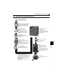
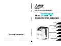
FR-HC2
INVERTER
FR-HC2
INSTRUCTION MANUAL
High power factor converter
CONVERTER
FR-HC2-7.5K to 75K
FR-HC2-H75K, H110K, H280K, H560K
OUTLINE
INSTALLATION AND
WIRING
1
2
MON
INSTRUCTION MANUAL
HEAD OFFICE: TOKYO BUILDING 2-7-3, MARUNOUCHI, CHIYODA-KU, TOKYO 100-8310, JAPAN
P.CPY
PWR
REGEN
DRIVE
PSCLR
MODE
SET
PARAMETERS
3
PROTECTIVE FUNCTIONS
4
STOP
RESET
MAINTENANCE AND
INSPECTION
SPECIFICATIONS
IB(NA)-0600381ENG-D (1109)MEE Printed in Japan
Specifications subject to change without notice.
D
5
6
Thank you for choosing the Mitsubishi High Power Factor Converter.
This Instruction Manual gives handling information and precautions for use of this equipment. Incorrect handling
might cause an unexpected fault. Before using the converter, please read this manual carefully to use the equipment
to its optimum.
Please forward this manual to the end user.
Do not attempt to install, operate, maintain or inspect the
converter until you have read through this Instruction
Manual and appended documents carefully and can use the
equipment correctly. Do not use this product until you have
a full knowledge of the equipment, safety information and
instructions.
In this Instruction Manual, the safety instruction levels are
classified into "WARNING" and "CAUTION"
WARNING
Incorrect
handling
may
cause
hazardous conditions, resulting in
death or severe injury.
CAUTION
Incorrect
handling
may
cause
hazardous conditions, resulting in
medium or slight injury, or may cause
only material damage.
The CAUTION
level may even lead to a serious
consequence according to conditions.
Both instruction levels must be followed because these are
important to personal safety.
SAFETY INSTRUCTIONS
1. Electric Shock Prevention
WARNING
z While power is ON or when the converter is running, do
not open the front cover. Otherwise you may get an
electric shock.
z Do not run the converter with the front cover removed.
Otherwise you may access the exposed high voltage
terminals or the charging part of the circuitry and get an
electric shock.
z Even if power is OFF, do not remove the front cover
except for wiring or periodic inspection. You may
accidentally touch the charged converter and get an
electric shock.
z Before wiring or inspection, power must be switched OFF.
To confirm that, LED indication of the operation panel
must be checked. (It must be OFF.) Any person who is
involved in wiring or inspection shall wait for at least 10
minutes after the power supply has been switched OFF
and check that there is no residual voltage using a tester
or the like. The capacitor is charged with high voltage for
some time after power OFF, and it is dangerous.
z This converter must be earthed (grounded). Earthing
(grounding) must conform with the requirements of
national and local safety regulations and electrical code
(NEC section 250, IEC 536 class 1 and other applicable
standards).
z Any person who is involved in wiring or inspection of this
equipment shall be fully competent to do the work.
z The product body must be installed before wiring.
Otherwise you may get an electric shock or be injured.
z Setting dial and key operations must be performed with
dry hands to prevent an electric shock. Otherwise you
may get an electric shock.
z Do not subject the cables to scratches, excessive stress,
heavy loads or pinching. Otherwise you may get an
electric shock.
z Do not change the cooling fan while power is ON. It is
dangerous to change the cooling fan while power is ON.
z Do not touch the printed circuit board or handle the cables
with wet hands. Otherwise you may get an electric shock.
2. Fire Prevention
CAUTION
z The converter must be installed on a nonflammable wall
without holes. Mounting it to or near flammable material
can cause a fire.
z If the converter has become faulty, the power of the
converter must be switched OFF. A continuous flow of
large current could cause a fire.
3.Injury Prevention
WARNING
z The voltage applied to each terminal must be the ones
specified in the Instruction Manual. Otherwise burst,
damage, etc. may occur.
z The cables must be connected to the correct terminals.
Otherwise burst, damage, etc. may occur.
z Polarity must be correct. Otherwise burst, damage, etc.
may occur.
z While power is ON or for some time after power-OFF, do
not touch the converter, reactor 1, reactor 2, outside box,
filter capacitor, and limit resistor as they will be extremely
hot. Touching these devices can cause a burn.
4. Additional Instructions
The following instructions must be also followed. If the
product is handled incorrectly, it may cause unexpected fault,
an injury, or an electric shock.
(1) Transportation and mounting
CAUTION
z The product must be transported in a suitable method
which corresponds to the weight. Failure to do so may
lead to injuries.
z Do not stack the boxes containing products higher than
the number recommended.
z The product must be installed to the position where
withstands the weight of the product according to the
information in the Instruction Manual.
z Do not install or operate the converter if it is damaged or
has parts missing.
z When carrying the converter, do not hold it by the front
cover or setting dial; it may fall off or fail.
z Do not stand or rest heavy objects on the product.
z The mounting orientation must be correct.
z Foreign conductive objects must be prevented from
entering the converter. That includes screws and metal
fragments or other flammable substance such as oil.
z As the converter is a precision instrument, do not drop or
subject it to impact.
z The product must be used under the following
environment. Otherwise the converter may be damaged.
Environment
Safety Instructions
Surrounding
air
-10°C to +50°C (non-freezing)
temperature
Ambient
90%RH or less (non-condensing)
humidity
Storage
-20°C to +65°C *1
temperature
Indoors (free from corrosive gas, flammable gas,
Atmosphere
oil mist, dust and dirt)
Altitude/
Maximum 1,000m above sea level. 5.9m/s2 or
vibration
less*2 at 10 to 55Hz (directions of X, Y, Z axes)
∗1 Temperature applicable for a short time, e.g. in transit.
∗2 2.9m/s2 or less for the 280K or higher.
A-1
(2) Trial run
(6) Disposal
CAUTION
z Before starting the operation, each parameter must be
confirmed and adjusted. A failure to do so may cause
some machines to make unexpected motions.
z Before starting the operation, the wiring of each
peripheral device must be checked. Faulty wiring may
cause some machines to make unexpected motions.
WARNING
z Any person must stay away from the equipment when the
retry function is set as it will restart suddenly after a trip.
key may not stop the operation
depending on the function setting status, separate circuit
and switch that make an emergency stop (power OFF,
etc.) must be provided.
z OFF status of the inverter start signal must be confirmed
before resetting a fault of the converter. If reset is
performed with the start signal ON, the converter starts
suddenly.
z The load must be always inverters. Connection of any
other electrical equipment to the converter output may
damage the equipment.
z Do not modify the equipment.
z Do not perform parts removal which is not instructed in
this manual. Doing so may lead to fault or damage of the
product.
CAUTION
z Do not use a magnetic contactor on the power input side
for frequent starting/stopping of the converter or the
inverter. Otherwise the life of the converter or the inverter
decreases.
z The effect of electromagnetic interference must be
reduced by using a noise filter or by other means.
Otherwise the electronic equipment used near the
converter or the inverter may be affected.
z When parameter clear or all parameter clear is performed,
the required parameters must be set again before starting
a operation because all parameters return to the initial
value.
z Before running a converter or an inverter which had been
stored for a long period, inspection and test operation
must be performed.
z For prevention of damage due to static electricity, nearby
metal must be touched before touching this product to
eliminate static electricity from your body.
(4) Emergency stop
CAUTION
z A safety backup such as an emergency brake must be
provided to prevent hazardous condition to the machine and
equipment in case of the converter and inverter failure.
z When the breaker, which is installed in the input side of
the converter, trips, the wiring must be checked for a fault
(short circuit), and internal parts of the converter and the
inverter for a damage, etc. The cause of the trip must be
identified and removed before turning ON the power of the
breaker.
z When any fault occurs, take an appropriate corrective
action, then reset the converter, and resume the
operation.
(5) Maintenance, inspection and parts replacement
CAUTION
z Do not carry out a megger (insulation resistance) test on
the control circuit of the converter.
A-2
(7) General instruction
Many of the diagrams and drawings in this Instruction
Manual show the converter without a cover or partially open
for explanation. Never operate the converter in this manner.
The cover must be always reinstalled and the instruction in
(3) Usage
z Since pressing the
CAUTION
z The converter must be treated as industrial waste.
this Instruction Manual must be followed when operating
the converter.
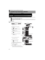
CONTENTS
OUTLINE
1.1
1
Pre-operation instructions .................................................................. 2
1.1.1
Features of FR-HC2 (high power factor converter) ........................................................................ 2
1.1.2
Japanese harmonic suppression guideline ................................................................................... 2
1.1.3
Product checking and parts identification ...................................................................................... 5
1.2
Converter and peripheral devices....................................................... 7
1.3
Precautions for selecting peripheral devices .................................... 8
1.3.1
Measures against noises (EMI) ...................................................................................................... 8
1.3.2
Peripheral device list .................................................................................................................... 11
1.3.3
Selecting the rated sensitivity current for the earth leakage circuit breaker ................................. 13
2 INSTALLATION AND WIRING
15
2.1
Removal and installation of the converter (FR-HC2) front cover..... 16
2.2
Removal and installation of the outside box (FR-HCB2) front
cover .................................................................................................. 18
2.3
Installation......................................................................................... 19
2.3.1
2.4
Converter placement .................................................................................................................... 19
Protruding the heatsink..................................................................... 21
2.4.1
When using a heatsink protrusion attachment (FR-A7CN) .......................................................... 21
2.4.2
Heatsink protrusion for 280K or higher ......................................................................................... 21
2.5
Installation of peripheral devices ..................................................... 23
2.5.1
Installation of reactor 1 and reactor 2 ........................................................................................... 23
2.5.2
Installation of the outside box (FR-HCB2-7.5K to 75K, FR-HCB2-H75K, H110K) ....................... 24
2.5.3
Installation of filter capacitor (FR-HCC2-H280K, H560K)............................................................. 25
2.5.4
Installation of inrush current limit resistor (FR-HCR2-H280K, H560K) ......................................... 25
2.5.5
Installation of stepdown transformer (FR-HCM2-H280K, H560K) ................................................ 26
2.6
Main circuit terminal specifications ................................................. 27
2.6.1
Description of main circuit terminal............................................................................................... 27
2.6.2
Terminal arrangement of the main circuit terminal ....................................................................... 27
2.6.3
Cable sizes of the main control circuit terminals and earth (ground) terminals ........................... 29
2.7
Wiring of main circuit
(FR-HC2-7.5K to 75K, FR-HC2-H75K, H110K) ................................... 31
2.7.1
Connection diagram (when using with the FR-A700 series) ........................................................ 31
2.7.2
Wiring of main circuit .................................................................................................................... 33
2.8
Wiring of main circuit (FR-HC2-H280K)............................................. 38
2.8.1
Connection diagram (when using with the FR-A700 series) ........................................................ 38
2.8.2
Wiring of main circuit .................................................................................................................... 40
2.9
Wiring of main circuit (FR-HC2-H560K)............................................. 44
I
CONTENTS
1
2.9.1
Connection diagram (when using with the FR-A700 series)......................................................... 44
2.9.2
Wiring of main circuit .................................................................................................................... 46
2.10 Notes on earthing (grounding).......................................................... 50
2.11 Compatible inverter for the high power factor converter................ 51
2.12 Wiring of several inverters to one converter ................................... 52
2.13 Wiring of control circuit .................................................................... 54
2.13.1 Description of control circuit terminal............................................................................................ 54
2.13.2 Changing the control logic ............................................................................................................ 56
2.13.3 Control circuit terminal layout ....................................................................................................... 58
2.13.4 Wiring instructions ........................................................................................................................ 59
2.13.5 When connecting the operation panel or parameter unit using a connection cable ..................... 60
2.13.6 Communication operation (computer link operation) .................................................................... 60
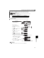
3
PARAMETERS
3.1
61
Operation panel (FR-DU07-CNV) ....................................................... 62
3.1.1
Names and functions of the operation panel (FR-DU07-CNV)..................................................... 62
3.1.2
Basic operation (factory setting) ................................................................................................... 63
3.1.3
Changing the parameter setting value.......................................................................................... 64
3.2
Parameter unit (FR-PU07),
parameter unit with battery pack (FR-PU07BB(-L)) ......................... 65
3.2.1
Parts identification of the parameter unit ...................................................................................... 65
3.2.2
Explanation of keys....................................................................................................................... 65
3.2.3
Monitoring function ....................................................................................................................... 66
3.2.4
Function menu .............................................................................................................................. 67
3.3
Parameter list ................................................................................... 69
3.4
Description of parameters ................................................................ 71
3.4.1
Displaying and hiding extended parameters (Pr. 0)..................................................................... 71
3.4.2
Input frequency to converter (Pr. 1, Pr. 2) ................................................................................... 71
3.4.3
Input terminal function selection (Pr. 3 to Pr. 7)........................................................................... 72
3.4.4
Operation selection of SOF signal and OH signal (Pr. 8, Pr. 9)................................................... 73
3.4.5
Output terminal function selection (Pr. 10 to Pr. 16).................................................................... 74
3.4.6
DC voltage control (Pr. 22 to Pr. 24, Pr. 80, Pr. 81) .................................................................... 75
3.4.7
Input current detection function (Y12 signal, Y13 signal, Pr. 25 to Pr. 30) .................................. 76
3.4.8
Displaying the life of the converter parts (Pr. 31 to Pr. 33) .......................................................... 77
3.4.9
Maintenance timer alarm (Pr. 34, Pr. 35)..................................................................................... 78
3.4.10 Cooling fan operation selection (Pr. 36) ...................................................................................... 79
3.4.11 Instantaneous power failure detection hold (Pr.44) ..................................................................... 79
3.4.12 Reference of the terminal FM (pulse train output) and terminal AM (analog output) (Pr. 45, Pr. 49,
Pr. 51, Pr. 53, Pr. 55, Pr. 56) ....................................................................................................... 80
3.4.13 DU/PU, terminal FM/AM monitor display selection (Pr. 46 to Pr. 48, Pr. 50, Pr. 52, Pr.54) ........ 82
3.4.14 Operation selection at instantaneous power failure (Pr. 57)........................................................ 85
II
3.4.15 Free parameter (Pr. 58, Pr. 59) ................................................................................................... 86
3.4.16 Key lock selection of operation panel(Pr. 61) .............................................................................. 86
3.4.18 Reset selection/disconnected PU detection/PU stop selection (Pr. 75) ...................................... 88
3.4.19 Parameter write disable selection (Pr. 77)................................................................................... 90
3.4.20 Current control (Pr. 82, Pr. 83) .................................................................................................... 91
3.4.21 Wiring and configuration of PU connector ................................................................................... 91
3.4.22 Initial settings and specifications of RS-485 communication (Pr. 117 to Pr. 124) ....................... 93
3.4.23 Mitsubishi inverter protocol (computer link communication) ........................................................ 94
3.4.24 Initial setting and specification for the CC-Link communication function (Pr.542 to Pr.544) ..... 105
3.4.25 Operation at a communication error (Pr.500 to Pr.502) ............................................................ 112
3.4.26 Communication EEPROM write selection (Pr. 342) .................................................................. 113
3.4.27 Setting of the parameter unit and operation panel (Pr. 145, Pr. 990, Pr. 991) .......................... 114
3.4.28 Terminal FM and AM calibration (calibration parameter C0 (Pr. 900), C1 (Pr. 901)) ................ 115
4
5
3.5
Parameter clear / All parameter clear ............................................ 117
3.6
Parameter copy and parameter verification................................... 118
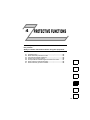
PROTECTIVE FUNCTIONS
121
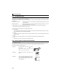
4.1
Troubleshooting............................................................................... 122
4.2
Reset method of protective function .............................................. 122
4.3
List of fault and alarm indications .................................................. 123
4.4
Causes and corrective actions ....................................................... 124
4.5
Correspondences between digital and actual characters ............. 131
4.6
Check and clear of the faults history ............................................. 132
4.7
Check first when you have a trouble .............................................. 134
MAINTENANCE AND INSPECTION
5.1
135
Inspection items.............................................................................. 136
5.1.1
Daily inspection .......................................................................................................................... 136
5.1.2
Periodic inspection ..................................................................................................................... 136
5.1.3
Daily and periodic inspection list ................................................................................................ 137
5.1.4
Checking the converter module .................................................................................................. 138
5.1.5
Cleaning ..................................................................................................................................... 138
5.1.6
Replacement of parts ................................................................................................................. 139
5.2
Measurement of main circuit voltages, currents and powers ....... 143
5.2.1
Insulation resistance test using megger ..................................................................................... 144
5.2.2
Pressure test .............................................................................................................................. 144
III
CONTENTS
3.4.17 Retry function (Pr. 65, Pr. 67 to Pr. 69) ....................................................................................... 87
6
SPECIFICATIONS
145
6.1
Rated specifications ....................................................................... 146
6.2
Common specifications .................................................................. 147
6.3
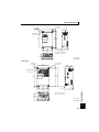
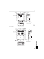
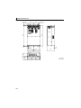
Outline dimensions ......................................................................... 148
6.3.1
Converter (FR-HC2) ................................................................................................................... 148
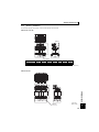
6.3.2
Reactor 1 (FR-HCL21)................................................................................................................ 153
6.3.3
Reactor 2 (FR-HCL22)................................................................................................................ 157
6.3.4
Difference between the reactor 1 (FR-HCL21) and the reactor 2 (FR-HCL22). ......................... 161
6.3.5
Outside box (FR-HCB2)............................................................................................................. 162
6.3.6
Filter capacitor (FR-HCC2) ........................................................................................................ 166
6.3.7
FR-HCM2................................................................................................................................... 167
6.3.8
Inrush current limit resistor (FR-HCR2) ..................................................................................... 171
6.3.9
Parameter unit ............................................................................................................................ 172
APPENDICES
173
Appendix 1 Instruction code list .................................................................................. 174
Appendix 2 Instructions for compliance with the EU Directives .............................. 175
Appendix 3 Instructions for UL and cUL ..................................................................... 177
<Abbreviations>
y
y
y
y
y
y
y
y
y
y
y
y
y
Converter: Mitsubishi high power factor converter (FR-HC2)
FR-HC2: Mitsubishi high power factor converter
Inverter: Mitsubishi inverter that supports FR-HC2
Reactor 1: Filter reactor 1 (FR-HC21)
Reactor 2: Filter reactor 2 (FR-HC22)
Limit resistor: Inrush current limit resistor (FR-HCR2)
Stepdown transformer: Stepdown transformer for power source of MCs
Limit MC: Inrush current limit MC
Pr. : Parameter number (Number assigned to function)
PU: Operation panel or option parameter unit (FR-PU07/FR-PU07BB)
FR-PU07: Option parameter unit (FR-PU07/FR-PU07BB)
PU operation: Operation using the PU
External operation: Operation using the control circuit signals
<Trademarks>
y Microsoft and Visual C++ are registered trademarks of Microsoft Corporation in the United States.
y Company and product names herein are the trademarks and registered trademarks of their respective owners.
<Marks>
REMARKS: Additional helpful contents and relations with other functions are written.
Note: Contents requiring caution or cases when set functions are not activated are written.
POINT: Useful contents and points are written.
: Content and description of an alarm or fault are written.
IV
1
OUTLINE
This chapter explains the "OUTLINE" for use of this product.
Always read the instructions before using the equipment.
1.1
1.2
1.3
Pre-operation instructions ........................................................... 2
Converter and peripheral devices ............................................... 7
Precautions for selecting peripheral devices ............................ 8
1
2
3
4
5
6
1
Pre-operation instructions
1.1
Pre-operation instructions
Incorrect handling may cause the equipment to operate improperly, its life to be reduced considerably, and in the worst case,
the converter and inverter to be damaged. Please handle the unit properly in accordance with the information on each section
as well as the precautions and instructions of this manual.
1.1.1
Features of FR-HC2 (high power factor converter)
Power supply harmonics generated from the converter part of an inverter may affect devices including a dynamo and a static
capacitor. Power supply harmonics differ from noise and leakage current in their generating source, frequency range and
transmission method. Power supply harmonic may be suppressed by using this converter, allowing the compliance with the
harmonic suppression guideline issued by the former Japanese Ministry of International Trade and Industry (currently the
Ministry of Economy, Trade and Industry). Conversion factor of the converter is K5=0 in the self-excitation three-phase bridge
circuit.
REMARKS
Set the following parameters to the inverter.
y Pr. 30 Regenerative function selection ="2"
y Pr. 19 Base frequency voltage (under V/F control), Pr. 83 Rated motor voltage (under control methods other than V/F control) =
"Rated motor voltage"
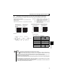
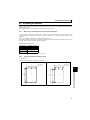
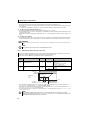
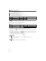
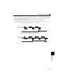
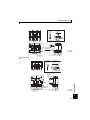
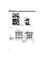
zPower supply harmonic suppression effect
(Example) FR-HC2-7.5K
(Condition) Load: 100%
Power factor: 1
[When the converter is not connected]
[When the converter is connected]
Input phase voltage(100V/div)
Input phase voltage(100V/div)
Input phase current
(50A/div)
Input phase current
(50A/div)
NOTE
y When the load is light, harmonic suppression effect declines.
y When the power supply voltage is unstable, harmonics from electric power system flow in, making the harmonic
current larger.
1.1.2
Japanese harmonic suppression guideline
Harmonic currents flow from the inverter to a power receiving point via a power transformer. The harmonic suppression
guideline was established to protect other consumers from these outgoing harmonics.
The all capacities and all models of the inverters used by the specific consumers became subject to the harmonic suppression
guideline for the consumers who receive high-voltage or special high-voltage (hereafter referred to as "Harmonic suppression
guideline for specific consumers").
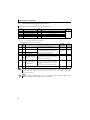
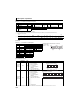
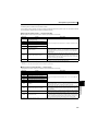
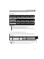
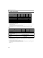
[Harmonic suppression guideline for specific consumers]
This guideline sets the maximum values of outgoing harmonic currents generated from a high-voltage or specially highvoltage consumer who will install, add or renew harmonic generating equipment. If any of the maximum values are
exceeded, this guideline requires the consumer to take certain suppression measures.
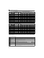
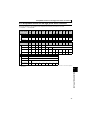
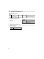
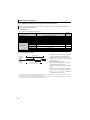
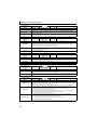
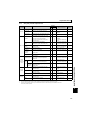
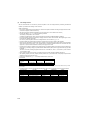
Table 1 Maximum outgoing harmonic current per 1kW contract
Received Power
Voltage
2
5th
7th
11th
13th
17th
19th
23rd
Over 23rd
6.6kV
3.5
2.5
1.6
1.3
1.0
0.9
0.76
0.70
22kV
1.8
1.3
0.82
0.69
0.53
0.47
0.39
0.36
33kV
1.2
0.86
0.55
0.46
0.35
0.32
0.26
0.24
Pre-operation instructions
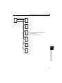
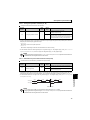
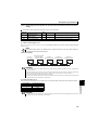
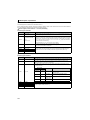
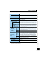
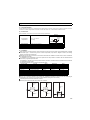
(1)
Application of the harmonic suppression guideline for specific consumers
Install, add or renew
equipment
Calculation of equivalent
capacity total
Equal to or less
than reference
capacity
Equivalent
capacity total
Above reference
capacity
Calculation of outgoing
harmonic current
More than upper limit
Not more than
harmonic current upper
limit?
Harmonic suppression
measures necessary
Equal to or less
than upper limit
Harmonic suppression
measures unnecessary
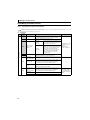
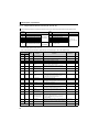
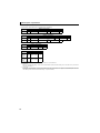
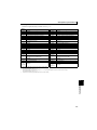
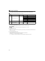
Table 2 Conversion Factors for FR-A700 Series
Classification
Circuit Type
Conversion Factor Ki
Without a reactor
3
Three-phase bridge
(Capacitor smoothed)
5
Self-excitation three-phase
bridge
K31=3.4
With a reactor (on AC side)
K32=1.8
With a reactor (on DC side)
K33=1.8
Without a reactor (on AC/DC side)
K34=1.4
With the converter
K5=0
1
Table 3 Equivalent Capacity Limits
Reference
Capacity
6.6kV
50kVA
22/33kV
300kVA
66kV or more
2000kVA
OUTLINE
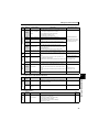
Received
Power Voltage
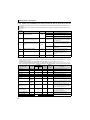
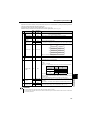
Table 4 Harmonic Content (Values at the fundamental current of 100%)
Reactor
Not used
5th
65
7th
41
11th
8.5
13th
7.7
17th
4.3
19th
3.1
23rd
2.6
25th
1.8
Used (AC side)
38
14.5
7.4
3.4
3.2
1.9
1.7
1.3
Used (DC side)
30
13
8.4
5.0
4.7
3.2
3.0
2.2
Used (on AC/DC side)
28
9.1
7.2
4.1
3.2
2.4
1.6
1.4
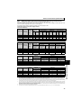
(a) Calculation of equivalent capacity P0 of harmonic generating equipment
The "equivalent capacity" is the capacity of a 6-pulse converter converted from the capacity of a consumer's harmonic
generating equipment and is calculated with the following equation. When the sum of equivalent capacity exceeds the limits
in Table 3, harmonics must be calculated in the following procedure.
P0 = Σ (Ki × Pi) [kVA]
Ki: Conversion factor(According to Table 2)
Pi: Rated capacity of harmonic generating equipment* [kVA]
i : Number indicating the conversion circuit type
* Rated capacity: Rated capacity is determined by the capacity of the applied
motor and found in Table 5. It should be noted that the rated capacity used here
is used to calculate generated harmonic amount and is different from the power
supply capacity required for actual inverter drive.
(b) Calculation of outgoing harmonic current
Outgoing harmonic current=fundamental wave current (value converted from received power voltage) × operation ratio ×
harmonic content
yOperation ratio: Operation ratio = actual load factor × operation time ratio during 30 minutes
yHarmonic content: Found in Table 4.
3
Pre-operation instructions
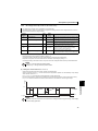
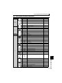
Table 5 Rated Capacity and Outgoing Harmonic Current during Inverter Run
Applied
Motor
(kW)
Rated Current
[A]
200V
400V
Fundamental
Wave Current
Converted from
6.6kV (mA)
Rated
Capacity
(kVA)
Harmonic Current Converted from 6.6kV (mA)
(No reactor, 100% operation ratio)
5th
7th
11th
13th
17th
19th
23rd
25th
0.4
1.61
0.81
49
0.57
31.85
20.09
4.165
3.773
2.107
1.519
1.274
0.882
0.75
2.74
1.37
83
0.97
53.95
34.03
7.055
6.391
3.569
2.573
2.158
1.494
1.5
5.50
2.75
167
1.95
108.6
68.47
14.20
12.86
7.181
5.177
4.342
3.006
2.2
7.93
3.96
240
2.81
156.0
98.40
20.40
18.48
10.32
7.440
6.240
4.320
3.7
13.0
6.50
394
4.61
257.1
161.5
33.49
30.34
16.94
12.21
10.24
7.092
5.5
19.1
9.55
579
6.77
376.1
237.4
49.22
44.58
24.90
17.95
15.05
10.42
7.5
25.6
12.8
776
9.07
504.4
318.2
65.96
59.75
33.37
24.06
20.18
13.97
11
36.9
18.5
1121
13.1
728.7
459.6
95.29
86.32
48.20
34.75
29.15
20.18
15
49.8
24.9
1509
17.6
980.9
618.7
128.3
116.2
64.89
46.78
39.24
27.16
18.5
61.4
30.7
1860
21.8
1209
762.6
158.1
143.2
79.98
57.66
48.36
33.48
22
73.1
36.6
2220
25.9
1443
910.2
188.7
170.9
95.46
68.82
57.72
39.96
30
98.0
49.0
2970
34.7
1931
1218
252.5
228.7
127.7
92.07
77.22
53.46
37
121
60.4
3660
42.8
2379
1501
311.1
281.8
157.4
113.5
95.16
65.88
45
147
73.5
4450
52.1
2893
1825
378.3
342.7
191.4
138.0
115.7
80.10
55
180
89.9
5450
63.7
3543
2235
463.3
419.7
234.4
169.0
141.7
98.10
Rated
Capacity
(kVA)
200V
400V
Fundamental
Wave Current
Converted from
6.6kV (mA)
75
245
123
7455
87.2
2237
969
626
373
350
239
224
164
90
293
147
8909
104
2673
1158
748
445
419
285
267
196
Applied
Motor
(kW)
Rated Current
[A]
Harmonic Current Converted from 6.6kV (mA)
(With a DC reactor, 100% operation ratio)
5th
7th
11th
13th
17th
19th
23rd
25th
110
357
179
10848
127
3254
1410
911
542
510
347
325
239
132
⎯
216
13091
153
3927
1702
1100
655
615
419
393
288
160
⎯
258
15636
183
4691
2033
1313
782
735
500
469
344
220
⎯
355
21515
252
6455
2797
1807
1076
1011
688
645
473
250
⎯
403
24424
286
7327
3175
2052
1221
1148
782
733
537
280
⎯
450
27273
319
8182
3545
2291
1364
1282
873
818
600
315
⎯
506
30667
359
9200
3987
2576
1533
1441
981
920
675
355
⎯
571
34606
405
10382
4499
2907
1730
1627
1107
1038
761
400
⎯
643
38970
456
11691
5066
3274
1949
1832
1247
1169
857
450
⎯
723
43818
512
13146
5696
3681
2191
2060
1402
1315
964
500
⎯
804
48727
570
14618
6335
4093
2436
2290
1559
1462
1072
560
⎯
900
54545
638
16364
7091
4582
2727
2564
1746
1636
1200
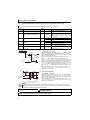
(c)Deciding whether to take harmonic suppression measures
When the outgoing harmonic current > the maximum value per 1kW contract × contract kW, a harmonic suppression
measures are required.
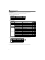
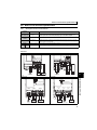
(d) Harmonic suppression measures
No.
Description
1
Harmonic current is suppressed by installing an AC reactor (FR-HAL) in the AC input side of the inverter
or a DC reactor (FR-HEL) in the DC bus line of the inverter, or by installing both.
2
High power factor
converter
(FR-HC2)
FR-HC2 is designed to switch ON/OFF the converter circuit to convert an input current waveform into a
sine wave, suppressing the harmonic current considerably. The converter (FR-HC2) is used with the
standard-equipped peripheral devices and accessories.
3
Power
factor improving static
capacitor
Using the power factor improving static capacitor with a series reactor has an effect of absorbing
harmonic currents.
4
Multi-phase operation
with transformers
Using two transformers with a phase angle difference of 30° as in and
combinations
provides an effect corresponding to 12 pulses and reduces low-degree harmonic currents.
5
Passive filter
(AC filter)
A capacitor and a reactor are used together to reduce impedance at specific frequencies, producing a
great effect of absorbing harmonic currents.
Active filter
This filter detects the current of the circuit, where harmonic current is generated, and generates the
harmonic current equivalent to the difference between that current and a fundamental wave current.
By doing so, the harmonic current at where it was detected can be suppressed, and great absorption of
harmonic current can be expected.
6
4
Item
Reactor
(FR-HAL, FR-HEL)
Pre-operation instructions
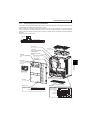
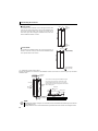
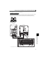
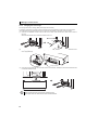
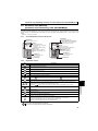
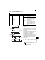
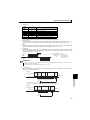
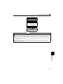
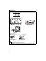
1.1.3
Product checking and parts identification
Unpack the product and check the capacity plate on the front cover and the rating plate on the side to ensure that the model
and rated output agree with your order and the product is intact.
When combined with a Mitsubishi general-purpose inverter and other converter accessories, this converter suppresses
harmonics according to the harmonic suppression guideline of the former Japanese Ministry of International Trade and
Industry (currently the Ministry of Economy, Trade and Industry). Carefully check the specifications including the applicable
capacities.
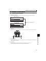
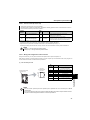
z High power factor converter model
FR-HC2-
7.5 K
Symbol Voltage class
Not used 200V class
H
400V class
Converter capacity
Represents the inverter capacity [kW]
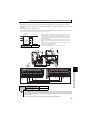
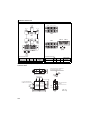
PU connector
(Refer to page 55)
Charge lamp
Lit when power is supplied
to the main circuit
(Refer to page 27)
Alarm lamp
Lit when the converter is in
fault.
Dedicated circuit board
for HC2
Main circuit terminal block
(Refer to page 27)
Control circuit
terminal block
(Refer to page 54)
1
OUTLINE
Power lamp
Lit when the control circuit
(R1/L11, S1/L21) is supplied
with power.
Cooling fan
(Refer to page 139)
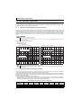
MON
P.CPY
PWR
REGEN
DRIVE
PSCLR
MODE
SET
STOP
RESET
Operation panel
(FR-DU07-CNV)
(Refer to page 62)
Connector for plug-in option
connection
(Refer to the instruction manual of options.)
Front cover
(Refer to page 16)
Combed shaped wiring cover
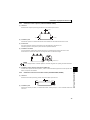
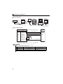
Capacity plate
Rating plate
Capacity plate
FR-HC2-7.5K
Rating plate
Converter model name
Converter model name Serial number
FR-HC2-7.5K
Applicable inverter capacity
Input rating
Rated output
Serial number
5
Pre-operation instructions
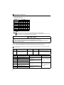
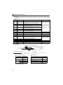
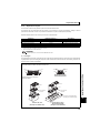
z Checking peripheral devices
y Peripheral devices
Always install the included peripheral devices. Check the model name of the each peripheral device.
For the 400V class peripheral devices, H is indicated in front of the model name.
FR-HC2-7.5K to 75K, FR-HC2-H75K, H110K
Peripheral Device
Description
Model Name
Quantity
FR-HC2-(H)
K
High power factor converter
1
FR-HCL21-(H)
K
Filter reactor 1
1
FR-HCL22-(H)
K
Filter reactor 2
1
FR-HCB2-(H)
K
Outside box *
1
* Terminal screws are enclosed for 7.5K and 15K. (M5 × 6)
FR-HC2-H280K, H560K
Peripheral Device
Model Name of Consisting Parts
Model Name
Description
560K
1
FR-HC2-H
K
FR-HC2-H
K
High power factor converter
1
FR-HCL21-H
K
FR-HCL21-H
K
Filter reactor 1
1
1
FR-HCL22-H
K
FR-HCL22-H
K
Filter reactor 2
1
1
FR-HCC2-H
K
Filter capacitor
1
3
MDA-1
filter capacitor alarm detector
—
3
FR-HCC2-H
K
FR-HCR2-H
K
0.96OHM BKO-CA1996H21
Inrush current limit resistor (without thermostat)
8
15
0.96OHM BKO-CA1996H31
Inrush current limit resistor (with thermostat)
1
3
1
1
Stepdown transformer for power source of MCs
1PH 630VA BKO-CA2001H06
FR-HCM2-H
K
(400V-200V)
S-N400FXYS AC200V 2A2B
Inrush current limit MC
—
3
S-N600FXYS AC200V 2A2B
Inrush current limit MC
1
—
SR-N4FX AC210V 4A
Buffer relay
1
2
TS-807B-5P
Terminal block
6
—
—
C152C481H21
Terminal block shorting conductor
6
C152C423H21
MC shorting conductor
—
6
MYQ4Z AC200/220
Mini relay for filter capacitor alarm detector
—
1
PYF14T
Mini relay terminal block
—
1
PYC-A1
Mini relay clip
—
2
M12×50 ZENNEJI
MC shorting conductor bolt (M12 × 50)
—
24
M12
MC shorting conductor nut (M12)
—
24
MIGAKI 12
MC shorting conductor washer (flat washer)
—
48
BANE 12
MC shorting conductor washer (spring washer)
—
24
SW-PW-P-NA M5 × 12
Inrush current limit resistor screw (M5 × 12)
—
54
y Eyebolt for hanging the converter (30K to 75K (200V class), 75K, 110K and 280K (400V class))
Capacity
200V
400V
Eyebolt Size
Quantity
30K, 55K
M8
2
75K
M10
2
75K
M8
2
110K
M10
2
280K
M12
2
y Instruction Manual
If you have any inquiry, or if damage is found on the product, please contact your sales representative.
6
Quantity
280K
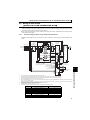
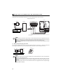
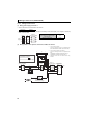
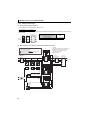
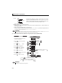
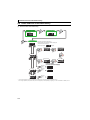
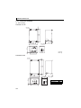
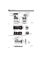
Converter and peripheral devices
Converter and peripheral devices
Three-phase AC power supply
Use within the permissible power
supply specifications of the converter.
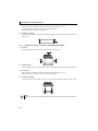
Moulded case circuit breaker (MCCB) or
earth leakage current breaker (ELB),
fuse
The breaker must be selected carefully since
an inrush current flows in the converter at
power ON.
Magnetic contactor (MC)
Install the magnetic contactor to
ensure safety.
High power factor converter
(FR-HC2)
Install and wire correctly.
Do not install the moulded case circuit
breaker (MCCB) between terminals P
and P, or N and N of the converter
and the inverter.
(Refer to page 31, 44)
Do not use this magnetic contactor to
start and stop the high power factor
converter and the inverter. Doing so will
shorten the life of the inverter and the
converter.
Reactor 1 (FR-HCL21)
Confirm that the capacity of the reactor
is selected according to the capacity of
the converter.
(Refer to page 33, 46)
R4S4 T4
PN
Fuse
Installation of a fuse is recommended
for safety.
Select a fuse according to the
connected motor capacity.
(Refer to page 11)
Outside box (FR-HCB2)*
Check that the capacity of the outside box
matches with the capacity of the high power
factor converter.
(Refer to page 31)
*Outside box is not available for 280K or higher.
Connect filter capacitors, inrush current limit
resistors, and magnetic contactors.
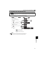
1
OUTLINE
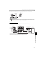
1.2
Inverter
Confirm that this is a FR-HC2
supporting inverter. (Refer to the
inverter catalogs for compatible
inverters.)
Connect an inverter that corresponds
with the each capacity of the converter.
Match the control logic (sink logic /
source logic) of the converter and the
inverter. (Refer to page 56)
Reactor 2 (FR-HCL22)
Confirm that the capacity of the reactor
is selected according to the capacity of
the converter. (Refer to page 33, 46)
Devices connected to the output
Do not install a power factor correction capacitor,
surge suppressor or radio noise filter on the output
side of the inverter. When installing a moulded case
circuit breaker on the output side of the inverter,
contact each manufacturer for selection of the
moulded case circuit breaker.
Motor
Connect the motor corresponds to the
each capacity.
Earth (Ground)
To prevent an electric shock, always earth (ground)
the motor and inverter.
Earth
(Ground)
7
Precautions for selecting peripheral devices
1.3
Precautions for selecting peripheral devices
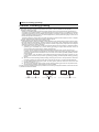
1.3.1
Measures against noises (EMI)
In this section, noises indicate those of more than 40th to 50th high frequencies in a power distribution system, which
generally assume irregular conditions.
Some noises enter the converter to adversely affect it, and others are radiated by the converter to adversely affect peripheral
devices. Though the converter is designed to be immune to noises, it handles low-level signals, so it requires the following
basic measures. Also, since the converter chops input voltage at high carrier frequency, it could generate noises. If these
noises affect peripheral devices, measures should be taken to suppress noises (EMI measures). The EMI measures differ
slightly depending on the noise transmission paths.
(1)
Basic measures
zDo not place the power cables (I/O cables) and signal cables of the converter in parallel with each other and do not
bundle them.
zFor the control signal cable and the connection cable with a detector, use twisted pair shield cables, and connect the
sheath of the shielded cables to the terminal SD.
zGround (earth) the reactor 1, reactor 2, outside box, converter, inverter, motor, etc. at one point.
(2)
Measures against noises which enter and affect the converter
When devices, which generate many noises, (for example, magnetic contactors, magnetic brakes, many relays) are
installed near the converter, the converter may malfunction because of the noises. In that case, the following measures
must be taken.
zProvide surge suppressors for the devices that generate many noises, and suppress the noises.
zInstall data line filters to signal cables.
zGround (earth) the connection cable with a detector and a control signal cable with a metal cable clamp.
(3)
Measures against the noises that are radiated by the converter to affect peripheral devices
Noises radiated by the converter are largely classified into three types: those radiated by the cables connected to the
converter and converter's main circuit (I/O), those electromagnetically and electrostatically inducted to the signal cables
of the peripheral devices close to the main circuit cable, and those transmitted through the power supply cables.
Converter
generated noise
Air propagated
noise
Noise directly radiated
from the converter
Path 1)
Noise radiated from
power supply cable
Path 2)
Noise radiated from
motor connection cable
Path 3)
5)
7)
7)
Electromagnetic
induction noise
Path 4), 5)
Electrostatic
induction noise
Path 6)
Electrical path
propagated noise
8
Telephone
2)
Reactor 1
Outside box
1)
Instrument
Noise propagated through
power supply cable
Path 7)
Noise from earth (ground)
cable due to leakage
current
Path 8)
Receiver
3)
Reactor 2
Sensor
power supply
Converter
Inverter
4)
Motor IM
6)
1)
3) Sensor
8)
Precautions for selecting peripheral devices
Noise
Measures
Transmission Path
When the devices, which handle low-level signals and are susceptible to noises (such as measuring
instruments, receivers and sensors), are installed near or in the same enclosure with the converter, or their
signal cables are placed near of in the same enclosure with the converter, air-transmitted noises may cause
malfunction of the devices. In that cases, the following measures must be taken.
(1) Install the easily affected devices as far away from the converter and inverter as possible.
(2) Place the easily affected signal cables as far away from the converter and inverter as possible.
1) 2) 3)
(3) Do not place the signal cables and power cables (converter I/O cables) in parallel with each other and do
not bundle them.
(4)Insert line noise filters ( FR-BLF, RC5128 (available product manufactured by Soshin Electric Co., Ltd.)) and
radio noise filters (FR-BIF) into the input side of the converter, and insert line noise filters (FR-BLF, RC5128
(available product manufactured by Soshin Electric Co., Ltd.)) into the output side of the inverter to
suppress cable-radiated noises.
(5) Use shield cables for signal cables and power cables and place them in individual metal conduits to
produce further effects.
When the signal cables are placed in parallel with or bundled with the power cables, magnetic and static
induction noises may be transmitted to the signal cables to cause malfunction of the devices. In that case, the
following measures must be taken.
(1) Install the easily affected devices as far away from the converter and inverter as possible.
4) 5) 6)
(2) Place the easily affected signal cables as far away from the converter, inverter, and their I/O cables as
possible.
(3) Do not place the signal cables and power cables ( I/O cables of the converter and inverter) in parallel with
each other and do not bundle them.
(4) Use shield cables for signal cables and power cables and place them in individual metal conduits to
produce further effects.
When the peripheral devices are connected to the same power supply line with the converter, convertergenerated noises may flow back through the power supply cable to the devices, causing malfunction of the
7)
devices. In that case, the following measures must be taken.
(1) Install radio noise filters (FR-BIF) to the power cable (input cable) of the converter.
(2) Install the line noise filters (FR-BLF, RC5128 (available product manufactured by Soshin Electric Co., Ltd.))
1
to the power cable (input cable) of the converter and to the power cable (output cable) of the inverter.
When a closed loop circuit is configured by connecting the wiring of a peripheral device to the converter,
leakage current may flow through the ground (earth) cable of the converter, causing malfunction of the device.
In that case, disconnecting the ground (earth) cable of the device may remove the malfunction.
OUTLINE
8)
9
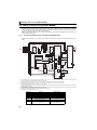
Precautions for selecting peripheral devices
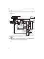
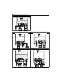
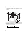
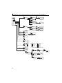
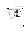
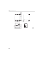
(4)
Using options to suppress noises
By using the radio noise filter (FR-BIF) and the line noise filter (FR-BLF), the noise radiated from the connection cable
can be suppressed. Refer to the Instruction Manual of each option for the detail of the radio noise filter (FR-BIF) and the
line noise filter (FR-BLF).
zExample (FR-A700 series)
Line noise filter *1 (FR-BLF, RC5128 *2)
or
Radio noise filter (FR-BIF)
Line noise filter
(FR-BLF, RC5128 *2)
Outside box (FR-HCB2)
FR-BIF
MCCB
MC
Power
supply
Limit resistor
Reactor 1
(FR-HCL21) R2/
R/
L1
R2/
L12
S/
L2
S2/
L22
T/ T2/
L3 L32
L12
R3/
L13
S2/
L22
S3/
L23
T2/
L32
T3/
L33
Reactor 2
(FR-HCL22)
Limit MC1
R3/ R4/
L13 L14
R4/L14
S3/ S4/
L23 L24
S4/L24
T3/ T4/
L33 L34
T4/L34
Auxiliary contact
(NO contact)
Overheat detection thermostat
for the limit resistor (NC contact)
Inverter
R/L1
U
S/L2
V
T/L3
W
R1/L11
S1/L21
P/+
N/B
ROH
Inrush current limit
resistor overheat
protection
ROH2
Contact
input
common
88R
MC
connection
terminal
88S
MC
connection
terminal
MC1
P/+
N/C
ROH1
Filter capacitors
Converter
(FR-HC2)
A
Inverter run
enable signal
Converter
RSO reset
88R
CVO During
converter run
Y1
Multi-purpose
output 1
Y2
Multi-purpose
output 2
SE
88S
Earth
(Ground)
Relay
output
(fault
output)
RDY
SD
Motor
X10
RES
SD
Reset
RES
Converter stop
SOF
Y3 Multi-purpose output 3
X1
SE2 Open collector output common
Open collector output common
Monitor switching
Monitor switching
Contact input common
24VDC power supply
(External transistor common)
X2
SD
FM
PU
connector
SD
+
-
Indicator
PC
R/L1
S/L2
T/L3
R1/L11
S1/L21
AM
5
(+) Analog signal output
(0 to 10VDC)
(-)
∗1
Install the line noise filter to the terminal R, S, and T of the converter, but not to the power supply. Refer to the Instruction Manual of the noise filter for the
∗2
installation procedure of the noise filter.
Product available on the market ............ RC5128: manufactured by Soshin Electric Co., Ltd.
NOTE
y Configure a system where the magnetic contactor at the converter input side shuts off the power supply at a failure of
the converter or the connected inverter. (The converter does not shut off the power supply by itself.) Failure to do so
may overheat and burn the resistors in the converter and the connected inverter.
10
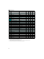
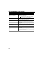
Precautions for selecting peripheral devices
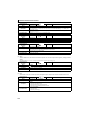
1.3.2
(1)
Peripheral device list
Circuit breakers and magnetic contactors
Check the model of the converter and select peripheral devices according to the capacity. Refer to the table below to prepare
appropriate peripheral devices.
z200V class
Converter Model
Moulded Case Circuit Breaker (MCCB) *1
or Earth Leakage Circuit Breaker (ELB)*2
(NF, NV type)
Magnetic Contactor
(MC)*3
FR-HC2-7.5K
50A
S-N25
FR-HC2-15K
75A
S-N50
FR-HC2-30K
150A
S-N80
FR-HC2-55K
300A
S-N180
FR-HC2-75K
350A
S-N300
z400V class
Converter Model
Moulded Case Circuit Breaker (MCCB) *1
or Earth Leakage Circuit Breaker (ELB)*2
(NF, NV type)
Magnetic Contactor
(MC)*3
FR-HC2-H75K
175A
S-N95
FR-HC2-H110K
250A
S-N180
FR-HC2-H280K
700A
S-N600
FR-HC2-H560K
1500A
S-N400 (three in parallel)
∗1
∗2
∗3
ySelect an MCCB according to the power supply capacity.
yInstall one MCCB per converter.
Converter
MCCB
Inverter
IM
Converter
Inverter
For the use in the United States or Canada, provide the appropriate UL and cUL listed fuse that is
IM
MCCB
suitable for branch circuit protection. (Refer to page 177)
Magnetic contactor is selected based on the AC-1 class.The electrical durability of magnetic contactor is 100,000 times.When the magnetic contactor is
used for emergency stop during motor driving, the electrical durability is 25 times.
When using the MC for emergency stop during motor driving or using on the motor side during commercial-power supply operation, select the MC with class
AC-3 rated current for the motor rated current.
NOTE
y When the MCCB on the converter input side trips, check for the wiring fault (short circuit), damage to internal parts of
the converter, etc. Identify the cause of the trip, then remove the cause and power ON the breaker.
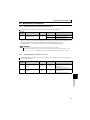
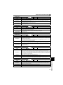
Fuse
Installation of a fuse is recommended between a high power factor converter and an inverter.
Select a fuse according to the capacity of the connected motor. When using a motor, of which the capacity is smaller than the
inverter capacity by two ranks or more, select the fuse with the capacity that is one rank lower than the inverter capacity. (Refer to
page 35 and 48 for details. )
[Fuse selection table]
z200V class
Recommended fuse
Motor
capacity (kW)
Fuse rating (A)
0.1
0.2
0.4
0.75
1.5
2.2
3.7
5.5
7.5
11
15
18.5
22
30
37
45
55
75
5
10
16
20
25
50
63
100
125
160
200
250
315
400
500
630
700
800
Model
6.900 CP GR 10.38 0005
6.900 CP GR 10.38 0010
6.900 CP GR 10.38 0016
6.900 CP GR 10.38 0020
6.900 CP GR 10.38 0025
6.9 URD 30 TTF 0050
6.9 URD 30 TTF 0063
6.9 URD 30 TTF 0100
6.9 URD 30 TTF 0125
6.9 URD 30 TTF 0160
6.9 URD 30 TTF 0200
6.9 URD 30 TTF 0250
6.9 URD 30 TTF 0315
6.9 URD 30 TTF 0400
6.9 URD 30 TTF 0500
6.9 URD 31 TTF 0630
6.9 URD 31 TTF 0700
6.9 URD 31 TTF 0800
Fuse holder (2 poles)
US102 (without fuse light melting indicator)
or US102I (with fuse light melting indicator)
—
—
—
—
—
—
—
—
—
—
—
—
—
* Manufacturer: Mersen Japan K.K.
Contact: Sun-Wa Technos Corporation
11
OUTLINE
(2)
1
Precautions for selecting peripheral devices
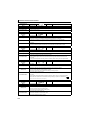
z400V
class
Motor
Recommended fuse
capacity (kW)
Fuse rating (A)
Model
0.4
12.5
6.900 CP GR 10.38 0012
0.75
16
6.900 CP GR 10.38 0016
1.5
16
6.900 CP GR 10.38 0016
2.2
20
6.900 CP GR 10.38 0020
3.7
30
6.900 CP GR 10.38 0030
5.5
50
6.9 URD 30 TTF 0050
—
7.5
50
6.9 URD 30 TTF 0050
—
11
80
6.9 URD 30 TTF 0080
—
15
125
6.9 URD 30 TTF 0125
—
18.5
125
6.9 URD 30 TTF 0125
—
22
160
6.9 URD 30 TTF 0160
—
30
200
6.9 URD 30 TTF 0200
—
37
250
6.9 URD 30 TTF 0250
—
45
315
6.9 URD 30 TTF 0315
—
55
350
6.9 URD 30 TTF 0350
—
75
450
6.9 URD 30 TTF 0450
—
90
500
6.9 URD 30 TTF 0500
—
110
550
6.9 URD 31 TTF 0550
—
132
630
6.9 URD 31 TTF 0630
—
160
800
6.9 URD 31 TTF 0800
—
185
900
6.9 URD 32 TTF 0900
—
6.9 URD 32 TTF 1000 or
Fuse holder (2 poles)
US102 (without fuse light melting indicator)
or US102I (with fuse light melting indicator)
—
220
1000
250
1250
280
1400
315
1600
355
1800
400
1800
450
2500
6.9 URD 33 TTF 1250 × 2 in parallel
—
500
2700
6.9 URD 32 TTF 0900 × 3 in parallel
—
560
2700
6.9 URD 32 TTF 0900 × 3 in parallel
—
6.9 URD 31 TTF 0630 × 2 in parallel
6.9 URD 33 TTF 1250 or
6.9 URD 31 TTF 0700 × 2 in parallel
6.9 URD 33 TTF 1400 or
6.9 URD 31 TTF 0800 × 2 in parallel
6.9 URD 232 TTF 1600 or
6.9 URD 31 TTF 0800 × 2 in parallel
6.9 URD 232 TTF 1800 or
6.9 URD 32 TTF 0900 × 2 in parallel
6.9 URD 232 TTF 1800 or
6.9 URD 32 TTF 0900 × 2 in parallel
—
—
—
—
—
* Manufacturer: Mersen Japan K.K.
Contact: Sun-Wa Technos Corporation
NOTE
y Install a fuse across terminal P/+ of the inverter and the converter and across terminal N/- of the inverter and the
converter.
[Estimated lifespan of fuse]
Part Name
Fuse
Estimated lifespan*
Replacement method
10 years
Replace with a new one
* Estimated lifespan for when the yearly average surrounding air temperature is 50°C (without corrosive gas, flammable gas, oil mist, dust and dirt etc.)
NOTE
y If the fuse melts down, wiring failure such as a short circuit may be the cause. Identify the problem and fix it before
replacing the fuse.
12
Precautions for selecting peripheral devices
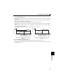
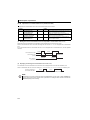
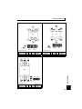
1.3.3
Selecting the rated sensitivity current for the earth leakage circuit breaker
When using the earth leakage circuit breaker with the inverter circuit, select its rated sensitivity current as follows.
y Breaker for harmonic and surge
Rated sensitivity current lΔn ≥ 10 × (lg1+lgn+lg2+lg3+lgm)
y Standard breaker
Rated sensitivity current lΔn≥ 10 × {lg1+lgn+lg2+3×(lg3+lgm)}
Example of leakage current per 1km during
the commercial power supply operation
when the CV cable is routed in metal conduit
Leakage current example of threephase induction motor during the
commercial power supply operation
(Three-phase three-wire delta
connection 400V60Hz)
(Totally-enclosed fan-cooled
type motor 400V60Hz)
(200V 60Hz)
120
100
80
60
40
20
0
2 3.5 8 142238 80150
5.5
30 60 100
leakage currents (mA)
Leakage currents (mA)
Leakage currents (mA)
(200V 60Hz)
2. 0
1. 0
0. 7
0. 5
0. 3
0. 2
0. 1
Cable size (mm2)
1. 5 3. 7 7. 5 15223755
2. 2 5.5 1118. 53045
120
100
80
60
40
20
0
2 3.5 8 142238 80150
5.5
30 60 100
Cable size (mm2)
leakage currents (mA)
Leakage current example of
three-phase induction motor
during the commercial
power supply operation
Example of leakage current of
cable path per 1km during the
commercial power supply operation
when the CV cable is routed in
metal conduit
lg1, lg2, lg3 : leakage current of cable path during
commercial power supply operation
lgn : leakage current of noise filter on the
converter input side
lgm : leakage currents of motor during commercial
power supply operation
2. 0
1. 0
0. 7
0. 5
0. 3
0. 2
0. 1
1. 5 3. 7 7. 5 15223755
2. 2 5.5 1118. 53045
Motor capacity (kW)
For " " connection, the amount of leakage current is appox.1/3 of the above value.
Motor capacity (kW)
<Example>
Selection Example
(for the diagram shown on the left) (mA)
ELB
5.5mm2 × 5m
Noise
filter
Converter
lg1
lgn
IM
Inverter
lg2
Breaker for
harmonic
and surge
5.5mm2 × 70m
3φ
200V 2.2kW
lgm
lg3
Standard
breaker
Leakage current lg1 (mA)
5m
33 × --------------- =0.17
Leakage current lgn (mA)
0 (without noise filter)
Leakage current lg2 (mA)
5m
33 × --------------- = 0.17
Leakage current lg3 (mA)
70m
33 × --------------- = 2.31
1000m
1000m
1
1000m
Leakage current lgm (mA)
0.18
Total leakage current (mA)
2.83
7.81
Rated sensitivity current
(≥lg×10)(mA)
30
100
OUTLINE
5.5mm2 × 5m
NOTE
y Install the earth leakage circuit breaker (ELB) on the input side of the converter.
y In the
connection earthed-neutral system, the sensitivity current is blunt against an earth (ground) fault in the
inverter output side. Earthing (Grounding) must conform with the requirements of national and local safety
regulations and electrical codes. (NEC section 250, IEC 536 class 1 and other applicable standards)
y When the breaker is installed on the output side of the inverter, it may be unnecessarily operated by harmonics even
if the effective value is less than the rating.
In this case, do not install the breaker since the eddy current and hysteresis loss will increase, leading to temperature
rise.
y The following models are the standard breakers....BV-C1, BC-V, NVB, NV-L, NV-G2N, NV-G3NA, NV-2F earth leakage
relay (except NV-ZHA), NV with AA neutral wire open-phase protection
The other models are designed for harmonic and surge suppression....NV-C/NV-S/MN series, NV30-FA, NV50-FA, BVC2, earth leakage alarm breaker (NF-Z), NV-ZHA, NV-H
13
MEMO
14
2
INSTALLATION
AND WIRING
This chapter provides an "INSTALLATION AND WIRING" of
this product.
Always read the instructions before using the equipment.
2.1
2.2
2.3
2.4
2.5
2.6
2.7
2.8
2.9
2.10
2.11
2.12
2.13
Removal and installation of the converter (FR-HC2) front
cover .............................................................................................. 16
Removal and installation of the outside box (FR-HCB2) front
cover .............................................................................................. 18
Installation ..................................................................................... 19
Protruding the heatsink................................................................ 21
Installation of peripheral devices ................................................ 23
Main circuit terminal specifications ............................................ 27
Wiring of main circuit (FR-HC2-7.5K to 75K, FR-HC2-H75K,
H110K)............................................................................................ 31
Wiring of main circuit (FR-HC2-H280K) ...................................... 38
Wiring of main circuit (FR-HC2-H560K) ...................................... 44
Notes on earthing (grounding) .................................................... 50
Compatible inverter for the high power factor converter ......... 51
Wiring of several inverters to one converter.............................. 52
Wiring of control circuit ............................................................... 54
1
2
3
4
5
6
15
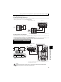
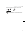
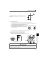
Removal and installation of the converter (FR-HC2) front cover
2.1
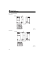
Removal and installation of the converter (FR-HC2) front cover
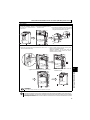
zRemoval of the operation panel
1) Loosen the two fixed screws on the operation panel.
(These screws cannot be removed.)
2) Push the left and right hooks of the operation panel and pull
the operation panel toward you to remove.
When reinstalling the operation panel, insert it straight to reinstall securely and tighten the screws of the operation panel.
15K or lower
zRemoval
1)Loosen the installation screws of the front
cover.
2)Pull the front cover toward you to remove by pushing an
installation hook using left fixed hooks as supports.
Front cover
Installation hook
zReinstallation
1) Insert the two fixed hooks on the left side
of the front cover into the sockets of the
inverter.
2) Using the fixed hooks as supports,
securely press the front cover against
the inverter. (Although installation can
be done with the operation panel
mounted, make sure that a connector
is securely fixed.)
MON
P.CPY
PWR
MON
P.CPY
PWR
REGE
N
MON
P.CPY
PWR
REGEN
Front
cover
16
3) Tighten the installation
screws and fix the front
cover.
REGEN
DRIVE
DRIVE
DRIVE
Front cover
Front cover
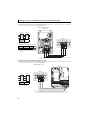
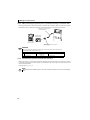
Removal and installation of the converter (FR-HC2) front cover
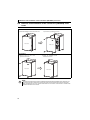
30K or higher
zRemoval
1) Loosen the installation screws of 2) Loosen the installation screw of 3) Push the two installation hooks on the right to
the front cover 1, and remove the
the front cover 2.
remove, and pull the front cover toward you
front cover 1.
using the left fixed hooks as supports.
Installation hook
Front cover 1
Front cover 2
zReinstallation
2) Using the fixed hooks as supports, securely press
the front cover 2 against the body.
(Although installation can be done with the
operation panel mounted, make sure that a
connector is securely fixed.)
Front cover 2
3) Tighten the installation screw of the front cover 2.
Front cover 2
4) Fit the front cover 1 and fix it with the
installation screws.
2
INSTALLATION AND WIRING
1) Insert the two fixed hooks on the left side of the front cover 2
into the sockets of the body.
Front cover 1
Front cover 2
REMARKS
yFor the 280K or higher, the front cover 1 is separated into two parts.
NOTE
y Fully make sure that the front cover has been reinstalled securely. Always tighten the installation screws of the front cover.
y The same serial number is printed on the capacity plate of the front cover and the rating plate of the converter. Before
reinstalling the front cover, check the serial numbers to ensure that the cover removed is reinstalled to the converter
from where it was removed.
17
Removal and installation of the outside box (FR-HCB2) front cover
2.2
Removal and installation of the outside box (FR-HCB2) front
cover
zRemoval
1) Loosen the installation screws of the front cover.
2) For removal, pull off the front cover.
Front cover
Front cover
zReinstallation
1) Securely press the front cover
against the outside box.
Front cover
2) Tighten the installation screws
and fix the front cover.
Front cover
NOTE
y Fully make sure that the front cover has been reinstalled securely. Always tighten the installation screws of the front cover.
y The same serial number is printed on the capacity plate of the front cover and the rating plate of the outside box.
Before reinstalling the front cover, check the serial numbers to ensure that the cover removed is reinstalled to the
outside box from where it was removed.
18
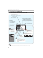
Installation
2.3
Installation
Incorrect installation and connection may cause the equipment to operate improperly and its lifespan to be reduced
considerably. Please handle the unit properly in accordance with the information on each section as well as the precautions in
this manual.
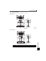
2.3.1
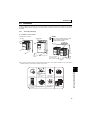
(1)
Converter placement
Installation of the converter
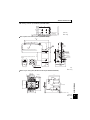
NOTE
Installation on the enclosure
7.5K, 15K
y When encasing multiple converters, install
30K or higher
them in parallel as a cooling measure.
y Install the converter vertically.
MON
P.CPY
REGEN
PWR
DRIVE
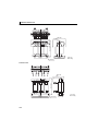
Vertical
Fix six points for H280K, and eight points
for H560K.
Refer to the clearance
on the next page.
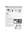
z The converter consists of precision mechanical and electronic parts. Never install or handle it in any of the following
conditions as doing so could cause an operation fault or failure.
INSTALLATION AND WIRING
2
Vibration
(5.9m/s2 or more* at 10
to 55Hz (directions of X,
Y, Z axes))
Direct sunlight
* 2.9m/s2 or more for the
280K or higher
Vertical mounting
(When installing two or
more converters, install Transportation by
holding the front cover
them in parallel.)
High temperature,
high humidity
Oil mist, flammable
gas, corrosive gas,
fluff, dust, etc.
Horizontal placement
Mounting to
combustible material
19
Installation
(2)
Clearances around the converter
To ensure ease of heat radiation and maintenance, leave at least the shown clearance around the converter. At least the
following clearance are required under the converter as a wiring space, and above the converter as a heat radiation space.
Surrounding air temperature and humidity
Measurement
position
5cm Converter 5cm
Measurement
position
5cm
Clearance (front)
55K or lower
Temperature:
-10°C to 50°C
Ambient humidity:
90% RH maximum
75K or higher
10cm
or more
5cm
or more
Clearance (side)
20cm or more
5cm
or more
10cm
or more
Converter
5cm
or more
10cm
or more
20cm or more
Leave enough clearances and take
cooling measures.
REMARKS
For replacing the cooling fan of the 280K or higher, 30cm of space is necessary in front of the inverter. Refer to page 139 for fan
replacement.
(3)
Converter mounting orientation
Mount the converter on a wall as specified. Do not mount it horizontally or any other way.
(4)
Above the converter
Heat is blown up from inside the converter by the small fan built in the unit. Any equipment placed above the converter should
be heat resistant.
(5)
Arrangement of multiple inverters and converters
When installing multiple inverters and converters in the
same enclosure, generally arrange them horizontally as
shown in the right figure (a). When it is inevitable to
arrange them vertically to minimize space, take such
measures as to provide guides since heat from the
bottom converters can increase the temperatures in the
top inverters, causing inverter failures.
When installing multiple inverters and converters, full
caution must be taken not to let the surrounding air
temperature of the converters and inverters exceed the
permissible value. Avoid the temperature to exceed the
value by providing ventilation and increasing the
enclosure size, etc.
(6)
Converter
Inverter
Enclosure
Inverter
Inverter
Guide
Guide
Converter
Converter
Guide
Enclosure
(b) Vertical arrangement
(a) Horizontal arrangement
Arrangement of multiple inverters and converters
Placement of ventilation fan and converter
Heat generated in the converter is blown up from the bottom of
the unit as warm air by the cooling fan. When installing a
ventilation fan for that heat, determine the place of ventilation
fan installation after fully considering an air flow. (Air passes
through areas of low resistance. Make an airway and airflow
plates to expose the converter to cool air.)
Converter
<Good example>
Converter
<Bad example>
Placement of ventilation fan and converter
20
Protruding the heatsink
2.4
Protruding the heatsink
When installing a converter inside an enclosure, the heat generated in the enclosure can be greatly reduced by protruding the
heatsink of the converter.
This installation method is recommended when downsizing the enclosure and such.
2.4.1
When using a heatsink protrusion attachment (FR-A7CN)
For the FR-HC2-7.5K to 75K and FR-HC2-H110K, a heatsink can be protruded outside the enclosure using a heatsink
protrusion attachment (FR-A7CN). (For the 280K or higher, the attachment is not necessary when the heatsink is to be
protruded.)
Refer to the table below for the applicable heatsink protrusion attachments.
For a panel cut dimension drawing and an installation procedure of the heatsink protrusion attachment (FR-A7CN) to the
converter, refer to a manual of "heatsink protrusion attachment".
zHeatsink protrusion attachments
Model Name
Applicable converter
FR-A7CN02
FR-HC2-7.5K
FR-A7CN04
FR-HC2-15K
FR-A7CN05
FR-HC2-30K
FR-HC2-75K
FR-A7CN09
FR-HC2-H110K
* For a combination other than above, please contact your sales representative.
2.4.2
Heatsink protrusion for 280K or higher
(1) Enclosure cut
Cut the enclosure according to the capacity of the converter.
zFR-HC2-H560K
zFR-HC2-H280K
6-M10 screw
6-M10 screw
771
315
315
300
2
INSTALLATION AND WIRING
1258
Hole
1300
21
300
Hole
21
15
984
954
15
662
21
Protruding the heatsink
(2) Moving and removing the back installation frames
zFR-HC2 -H280K
Shift
Upper
installation
frame
One installation frame is attached to each of the upper and lower parts
of the converter. Change the position of the rear side installation frame
on the upper and lower sides of the converter to the front side as
shown on the right. When changing the installation frames, make sure
that the installation orientation is correct.
Lower
installation
frame
Shift
zFR-HC2-H560K
Removal
The converter has installation frames: two on the top and the two on
Upper installation
frame (rear side)
the bottom. As shown on the right, remove the back installation frames
on the top and bottom of the converter.
Removal
Lower installation
frame (rear side)
(3) Installing the converter to the enclosure
Protrude the heatsink of the converter from the installation enclosure, and secure the converter using the top and bottom
installation frames.
Enclosure
Inside the
Exhausted air
enclosure
*
*The enclosure enclosing FR-HC2-H280K and higher
has a finger guard on its back. The thickness of the
Converter
enclosure should be less than 10mm (*), and do not
place anything around the finger guard to avoid contact
Installation with the finger guard.
frame
Enclosure
140
Finger guard
6
10*
Dimension of
Cooling the outside of
wind the enclosure
D1
Model
FR-HC2-H280K, H560K
D1
184
NOTE
• Protruding area contains a cooling fan, so it cannot be used in the environment where water drops, oil mist, dust and
other substances exist.
• Foreign substances such as screws and dust must be prevented to enter in the converter or the cooling fan section.
22
Installation of peripheral devices
2.5
Installation of peripheral devices
2.5.1
(1)
Installation of reactor 1 and reactor 2
Model name confirmation
Take caution as the appearances of the reactor 1 (FR-HCL21) and the reactor 2 (FR-HCL22) are very similar.
Reactor 1(FR-HCL21)
AC REACTOR
MODEL
FR-HCL21-XXX
SERIAL XXXXX
Check "MODEL" on the rating plates of the reactor 1
(FR-HCL21) and the reactor 2 (FR-HCL22).
Reactor 2(FR-HCL22)
AC REACTOR
MODEL
FR-HCL22-XXX
SERIAL XXXXX
(2)
Clearance
Because the reactor 1 (FR-HCL21) and the reactor 2 (FR-HCL22) generate heat, leave sufficient space around them.
10cm or more
5cm or more
(3)
5cm or more
Installation place
Install the reactor 1 (FR-HCL21) and the reactor 2 (FR-HCL22) on nonflammable material. Direct installation on a
flammable material will cause a fire.
(4)
Environment
Avoid places where the equipment is subjected to oil mist, flammable gases, fluff, dust, dirt, etc.
Install the equipment in a clean place or protect them from suspended substances.
23
INSTALLATION AND WIRING
2
Installation of peripheral devices
(5)
Installation orientation
To prevent looseness, install the reactor 1 (FR-HCL21) and the reactor 2 (FR-HCL22) on a horizontal surface securely
with screws or bolts.
Do not install them on a vertical wall. Install them on a mounting stand which can withstand their weight.
NOTE
Since the charged sections of the reactor 1 and the reactor 2 are uncovered, fully protect them to prevent ground fault
and electric shock.
2.5.2
(1)
Installation of the outside box (FR-HCB2-7.5K to 75K, FR-HCB2-H75K, H110K)
Clearance
10cm or more
5cm or more
(2)
5cm or more
Installation area
Mount the outside box (FR-HCB2) on nonflammable material. Installing it directly on flammable material will cause a fire.
(3)
Surrounding environment
Avoid places where the equipment is subjected to oil mist, flammable gases, fluff, dust, dirt, etc.
Install the equipment in a clean place or protect it from suspended substances.
(4)
Installation
Install the outside box (FR-HCB2) vertically.
NOTE
Since the charged sections of the outside box are
uncovered, take sufficient protective measures to
avoid ground faults and electric shocks.
Vertical
24
Installation of peripheral devices
2.5.3
(1)
Installation of filter capacitor (FR-HCC2-H280K, H560K)
Clearance
Because the filter capacitor (FR-HCC2) generates heat, leave sufficient space around it.
10cm or more
10cm or more
(2)
10cm or more
Installation place
Install the filter capacitor on nonflammable material. Direct installation on a flammable material will cause a fire.
(3)
Environment
Avoid places where the equipment is subjected to oil mist, flammable gases, fluff, dust, dirt, etc.
Install the equipment in a clean place or protect them from suspended substances.
(4)
Installation orientation
To prevent looseness, install the filter capacitor (FR-HCC2) on a horizontal surface securely with screws or bolts.
Do not install it on a vertical wall. Install it on a mounting stand which can withstand its weight.
Installation foot
NOTE
Since the charged sections of the filter capacitor is uncovered, fully protect it to prevent ground fault and electric
shock.
Installation of filter capacitor alarm detector (560K only)
To install a filter capacitor alarm detector (MDA-1), refer to the Instruction Manual appended to the filter capacitor alarm
detector, and perform the installation.
2.5.4
(1)
Installation of inrush current limit resistor (FR-HCR2-H280K, H560K)
Clearance
Because the limit resistor (FR-HCR2) generates heat, leave sufficient space around it.
3cm or
more
(2)
3cm or more
3cm or
more
Installation place
Install the limit resistor (FR-HCR2) on nonflammable material. Installing directly on or near a flammable material will
cause a fire.
25
2
INSTALLATION AND WIRING
(5)
Installation of peripheral devices
(3)
Environment
Avoid places where the equipment is subjected to oil mist, flammable gases, fluff, dust, dirt, etc.
Install the equipment in a clean place or protect it from suspended substances.
Do not place a flammable material near the equipment.
(4)
Installation orientation
To prevent looseness, install the inrush current limit resistor (FR-HCR2) on a horizontal or vertical surface securely with
screws or bolts.
2.5.5
(1)
Installation of stepdown transformer (FR-HCM2-H280K, H560K)
Clearance
Because the stepdown transformer generates heat, leave sufficient space around it.
10cm or more
10cm or more
(2)
10cm or more
Installation place
Install the stepdown transformer on nonflammable material. Direct installation on a flammable material will cause a fire.
(3)
Environment
Avoid places where the equipment is subjected to oil mist, flammable gases, fluff, dust, dirt, etc.
Install the equipment in a clean place or protect it from suspended substances.
(4)
Installation orientation
To prevent looseness, install the stepdown transformer on a horizontal or vertical surface securely with screws or bolts.
NOTE
Since the charged section of the stepdown transformer is uncovered, fully protect it to prevent ground fault and electric
shock.
26
Main circuit terminal specifications
2.6
2.6.1
Main circuit terminal specifications
Description of main circuit terminal
Terminal
Symbol
Terminal Name
Description
R/L1, S/L2, T/L3 Power input
These terminals are used to detect power phase and power voltage, and to input control
power. Connect them to the commercial power supply. If the inverter is operated without
connecting them to the commercial power supply, the converter will be damaged.
R4/L14, S4/L24,
T4/L34
Power input
Connect them to the reactor 2.
R1/L11, S1/L21
Power supply for
control circuit
These terminals are connected to the phase detection terminals R/L1 and S/L2 in the initial
status. To retain the fault display and fault output, remove the jumpers (cables) and apply
external power to these terminals.
Inverter connection
Connect them to the inverter terminals P/+ and N/-.
Earth (Ground)
For earthing (grounding) the converter chassis. It must be earthed (grounded).
P/+, N/-
2.6.2
Terminal arrangement of the main circuit terminal
200V class
FR-HC2-7.5K
FR-HC2-15K
Screw size (M4)
Charge lamp
R1/L11 S1/L21
Charge lamp
Screw size (M6)
*
*
R1/L11 S1/L21
P/+
N/-
R/L1 S/L2 T/L3
R4/
L14
T4/
L34
S4/
L24
N/-
P/+
Screw size (M5)
R/L1 S/L2 T/L3 R4/ S4/ T4/
L14 L24 L34
Screw size
(M5)
Power supply
Screw size
(M6)
Inverter
Reactor 2
Power supply
2
Inverter
Reactor 2
* Screw size for terminals R1/L11 and S1/L21 is M4.
FR-HC2-55K
Screw size (M4)
Screw size (M4)
R1/L11 S1/L21
R1/L11 S1/L21
Charge lamp
Charge lamp
Screw size
(M4)
Screw size
(M8)
Screw size
(M10)
R4/ S4/ T4/
L14 L24 L34
R/ S/ T/
L1 L2 L3
4㧛.
5㧛.
0
P/+
2
$%&*
Screw size
(M12)
R4/
L14
S4/
L24
Reactor 2
Screw size
(M4)
T4/
L34
Screw size
(M12)
0
2
N/-
P/+
R/ S/ T/
L1 L2 L3
Screw
size
(M6)
Screw
size
(M6)
Power
supply
N/-
6㧛.
INSTALLATION AND WIRING
FR-HC2-30K
Screw size
(M6)
Inverter
Reactor 2
Power supply
Inverter
27
Main circuit terminal specifications
FR-HC2-75K
Screw size (M4)
R1/L11 S1/L21
Charge lamp
Screw size
(M12)
Screw size
(M4)
T4/
L34
S4/
L24
R4/
L14
4㧛.
Screw size
(M12)
5㧛.
6㧛.
0
R/ S/ T/
L1 L2 L3
2
P/+
N/-
Screw size
(M10)
Inverter
Reactor 2
Power supply
400V class
FR-HC2-H75K
FR-HC2-H110K
Screw size (M4)
Screw size (M4)
R1/L11 S1/L21
R1/L11 S1/L21
Charge lamp
Screw size (M10)
Charge lamp
Screw size
(M4)
Screw size (M10)
Screw size
(M10)
R4/
L14
R/ S/ T/
L1 L2 L3
N/-
R4/ S4/ T4/
L14 L24 L34
S4/
L24
T4/
L34
P/+
N/-
P/+
$%&*
$%&*
Screw
size
(M10)
R/ S/ T/
L1 L2 L3
Power supply
Reactor 2
Screw
size
(M10)
Screw size
(M4)
Screw size
(M10)
Power supply
Reactor 2
Inverter
Inverter
FR-HC2-H280K
FR-HC2-H560K
Screw size (M4)
Screw size (M4)
R1/L11 S1/L21
R1/L11 S1/L21
Charge lamp
Charge lamp
Screw size (M12)
Screw size (M12)
Screw size
(M4)
㩡
Screw size
(M10)
R/ S/ T/
L1 L2 L3
R4/
L14
S4/
L24
T4/
L34
N/-
P/+
R4/
L14
S4/
L24
T4/
L34
N/-
P/+
4㧛. 5㧛. 6㧛.
$%&*
Screw
size
(M10)
R4/
L14
S4/
L24
Power supply Reactor 2
28
T4/
L34
N/-
P/+
Screw
size
(M10)
R4/
L14
S4/
L24
Screw
size
(M10)
T4/
L34
R/ S/ T/
L1 L2 L3
Screw size (M4)
N/-
P/+
Inverter
Reactor 2
Inverter
Power supply
Main circuit terminal specifications
2.6.3
Cable sizes of the main control circuit terminals and earth (ground) terminals
Select the recommended cable size to ensure that a voltage drop will be 2% max.
If the wiring distance is long between the inverter and motor, a main circuit cable voltage drop will cause the motor
torque to decrease especially at the output of a low frequency.
The following table indicates a selection example for the wiring length of 20m
z 200V class (when input power supply is 220V)
<Converter (FR-HC2)>
Crimping
Model Name
FR-HC2-7.5K
FR-HC2-15K
FR-HC2-30K
FR-HC2-55K
FR-HC2-75K
Terminal
Tightening
Torque
Screw Size
Nym
M5
M6
M8/
M10(M6)*4
M12(M6)*4
M12(M10)*4
Cable Size
AWG/MCM *2
Terminal
HIV, etc.(mm2) *1
PVC, etc.(mm2) *3
R4/L14,
R4/L14,
R4/L14,
R4/L14,
P/+, N/P/+, N/- Earthing
P/+, N/- Earthing
S4/L24, P/+, N/- S4/L24,
S4/L24,
S4/L24,
*5
*5
*5
cable
cable
T4/L34
T4/L34
T4/L34
T4/L34
2.5
4.4
8-5
22-6
5.5-5
14-6
8
22
5.5
14
5.5
14
8
4
10
6
10
25
6
16
6
16
7.8/14.7
60-8
38-10
60
38
22
1/0
1
50
50
25
24.5
24.5
125-12
100-12
100-12
100-12
125
100
100
100
38
38
250
4/0
4/0
4/0
120
95
95
95
70
50
<Outside box (FR-HCB2)>
Cable Size
Crimping
2
AWG/MCM
*2
Terminal
HIV,
etc.(mm
)
*1
PVC, etc.(mm2) *3
Tightening
Terminal
R2/L12, S2/L22, R2/L12, S2/L22,
R2/L12, S2/L22, R2/L12, S2/L22,
Model Name
Torque
Earthing
Earthing
Screw Size
T2/L32
T2/L32
T2/L32
T2/L32
Nym
R3/L13, S3/L23, R3/L13, S3/L23,
cable R3/L13, S3/L23, R3/L13, S3/L23,
cable
T3/L33
T3/L33
T3/L33
T3/L33
FR-HCB2-7.5K
M5
FR-HCB2-15K
M5
FR-HCB2-30K
M6
FR-HCB2-55K M8(M6) *4
FR-HCB2-75K M12(M10) *4
2.5
2.5
4.4
7.8
24.5
8-5
22-5
60-6
125-8
100-12
8
22
60
125
100
5.5
14
22
38
38
8
4
1/0
250
4/0
10
25
50
120
95
6
16
25
35
35
<Reactor1 (FR-HCL21)>
FR-HCL21-7.5K
FR-HCL21-15K
FR-HCL21-30K
FR-HCL21-55K
FR-HCL21-75K
Tightening
Torque
Screw Size
Nym
M5
M6
M8
M12
M12
2.5
4.4
7.8
24.5
24.5
Cable Size
Crimping
AWG/MCM *2
Terminal
HIV, etc.(mm2)*1
PVC, etc.(mm2) *3
R/L1, S/L2, T/L3
R/L1, S/L2, T/L3
R/L1, S/L2, T/L3
R/L1, S/L2, T/L3
R2/L12, S2/L22, T2/L32 R2/L12, S2/L22, T2/L32 R2/L12, S2/L22, T2/L32 R2/L12, S2/L22, T2/L32
8-5
22-6
60-8
125-12
100-12
8
22
60
125
100
8
4
1/0
250
4/0
10
25
50
120
95
2
<Reactor2 (FR-HCL22)>
Model Name
FR-HCL22-7.5K
FR-HCL22-15K
FR-HCL22-30K
FR-HCL22-55K
FR-HCL22-75K
∗1
∗2
∗3
∗4
∗5
Terminal
Screw Size
M5
M6
M8
M12
M12
Tightening
Torque
Nym
2.5
4.4
7.8
24.5
24.5
Crimping
Cable Size
AWG/MCM
*2
HIV,
PVC, etc.(mm2) *3
Terminal
R3/L13, S3/L23, T3/L33 R3/L13, S3/L23, T3/L33 R3/L13, S3/L23, T3/L33 R3/L13, S3/L23, T3/L33
R4/L14, S4/L24, T4/L34 R4/L14, S4/L24, T4/L34 R4/L14, S4/L24, T4/L34 R4/L14, S4/L24, T4/L34
etc.(mm2)*1
8-5
22-6
60-8
125-12
100-12
8
22
60
125
100
8
4
1/0
250
4/0
10
25
50
120
95
For the 55K or lower, the cable size is that of the cable (HIV cable (600V class 2 vinyl-insulated cable) etc.) with continuous maximum permissible temperature of
75°C. It assumes that the surrounding air temperature is 50°C or less and the wiring distance is 20m or less.
For the 75K or higher, the recommended cable size is that of the cable (LMFC (heat resistant flexible cross-linked polyethylene insulated cable) etc.) with
continuous maximum permissible temperature of 90°C. It assumes that the surrounding air temperature is 50°C or less and wiring is performed in an enclosure.
The recommended cable size is that of the cable (THHW cable) with continuous maximum permissible temperature of 75°C. It assumes that the surrounding
air temperature is 40°C or less and the wiring distance is 20m or less. (Selection example for use mainly in the United States.)
For the 15K or lower, the recommended cable size is that of the cable (PVC cable) with continuous maximum permissible temperature of 70°C. It assumes
that the surrounding air temperature is 40°C or less and the wiring distance is 20m or less. For the 30K or higher, the recommended cable size is that of the
cable (XLPE cable) with continuous maximum permissible temperature of 90°C. It assumes that the surrounding air temperature is 40°C or less and wiring is
performed in an enclosure. (Selection example for use mainly in Europe.)
Screw size for earthing (grounding) is indicated in parenthesis.
If a cable thinner than the recommended cable size is used, it may not be protected by the DC fuse. (Refer to page 11 for the fuse selection.)
29
INSTALLATION AND WIRING
Model Name
Terminal
Main circuit terminal specifications
z 400V class (when input power supply is 440V)
<Converter (FR-HC2)>
Crimping
Model Name
FR-HC2-H75K
FR-HC2-H110K
FR-HC2-H280K
FR-HC2-H560K
Terminal
Tightening
Screw Size
M10(M10)
M10(M10)
M12(M10)
M12(M10)
*4
*4
*4
*4
Torque
Nym
14.7
14.7
24.5
24.5
Cable Size
AWG/MCM *2
2
Terminal
HIV, etc.(mm ) *1
PVC, etc.(mm2) *3
R4/L14,
R4/L14,
R4/L14,
R4/L14,
P/+, N/P/+, N/- Earthing
P/+, N/- Earthing
S4/L24, P/+, N/- S4/L24,
S4/L24,
S4/L24,
*5
*5
*5
cable
cable
T4/L34
T4/L34
T4/L34
T4/L34
38-10
60-10
200-12
C2-250
38-10
60-10
150-12
C2-250
38
60
200
2 × 250
38
60
2 × 125
3 × 250
38
38
60
100
1
1/0
400
2 × 500
1
2/0
2 × 350
2 × 600
50
50
185
2 × 240
50
70
2 × 120
3 × 240
25
35
120
2 × 150
<Outside box (FR-HCB2)>
Cable Size
AWG/MCM *2
HIV, etc.(mm2) *1
PVC, etc.(mm2) *3
Tightening
Terminal
R2/L12, S2/L22, R2/L12, S2/L22,
R2/L12, S2/L22, R2/L12, S2/L22,
Torque
Model Name
Earthing
Screw Size
Earthing
T2/L32
T2/L32
T2/L32
T2/L32
Nym
cable R3/L13, S3/L23, R3/L13, S3/L23,
R3/L13, S3/L23, R3/L13, S3/L23,
cable
T3/L33
T3/L33
T3/L33
T3/L33
Crimping
Terminal
FR-HCB2-H75K M8(M8) *4
FR-HCB2-H110K M10(M10) *4
FR-HCC2-H280K M12(M8) *4
FR-HCC2-H560K M12(M8) *4
7.8
14.7
15.0
25.0
38-10
60-10
60-12
38-12
38
60
60
38
38
38
60
38
1
1/0
1/0
1
50
50
50
50
25
25
50
50
<Reactor1 (FR-HCL21)>
Model Name
FR-HCL21-H75K
FR-HCL21-H110K
FR-HCL21-H280K
FR-HCL21-H560K
Terminal
Screw Size
M10
M12
M12
M12
Tightening
Torque
Nym
14.7
24.5
24.5
24.5
Cable Size
AWG/MCM *2
HIV, etc.(mm2) *1
PVC, etc.(mm2) *3
R/L1,S/L2,T/L3
R/L1,S/L2,T/L3
R/L1,S/L2,T/L3
R/L1,S/L2,T/L3
R2/L12,S2/L22,T2/L32 R2/L12,S2/L22,T2/L32 R2/L12,S2/L22,T2/L32 R2/L12,S2/L22,T2/L32
Crimping
Terminal
38-10
60-12
200-12
C2-250
38
60
200
2 × 250
1
1/0
400
2 × 500
50
50
185
2 × 240
<Reactor2 (FR-HCL22)>
Model Name
FR-HCL22-H75K
FR-HCL22-H110K
FR-HCL22-H280K
FR-HCL22-H560K
∗1
∗2
Terminal
Screw Size
M10
M10
M12
M12
Tightening
Torque
Nym
14.7
14.7
24.5
24.5
Cable Size
AWG/MCM *2
HIV, etc.(mm2) *1
PVC, etc.(mm2) *3
R3/L13,S3/L23,T3/L33 R3/L13,S3/L23,T3/L33 R3/L13,S3/L23,T3/L33 R3/L13,S3/L23,T3/L33
R4/L14,S4/L24,T4/L34 R4/L14,S4/L24,T4/L34 R4/L14,S4/L24,T4/L34 R4/L14,S4/L24,T4/L34
Crimping
Terminal
38-10
60-10
200-12
C2-250
38
60
200
2 × 250
1
1/0
400
2 × 500
50
50
185
2 × 240
The recommended cable size is that of the cable (LMFC (heat resistant flexible cross-linked polyethylene insulated cable) etc.) with continuous maximum
permissible temperature of 90°C. It assumes the surrounding air temperature of 50°C or lower and in-enclosure wiring.
The recommended cable size is that of the cable (THHN cable) with continuous maximum permissible temperature of 90°C. It assumes that the surrounding
air temperature is 40°C or less and in-enclosure wiring. (Selection example for use mainly in the United States.)
∗3
The recommended cable size is that of the cable (XLPE cable) with continuous maximum permissible temperature of 90°C. It assumes the surrounding air
temperature is 40°C or lower and in-enclosure wiring. (Selection example for use mainly in Europe.)
∗4
∗5
30
Screw size for earthing (grounding) is indicated in parentheses.
If a cable thinner than the recommended cable size is used, it may not be protected by the DC fuse. (Refer to page 11 for the fuse selection.)
Wiring of main circuit (FR-HC2-7.5K to 75K, FR-HC2-H75K, H110K)
2.7
Wiring of main circuit
(FR-HC2-7.5K to 75K, FR-HC2-H75K, H110K)
z Perform wiring securely to conform with the harmonic suppression guideline of the former Ministry of International
Trade and Industry (currently the Japanese Ministry of Economy, Trade and Industry). Incorrect wiring causes the
converter to display an alarm or causes an fault or damage.
z Refer to the Instruction Manual of each inverter for the wiring of the inverter. Special attention must be paid to the
wiring length and wire gauge.
2.7.1
Connection diagram (when using with the FR-A700 series)
Connection method differs by the inverter series. Perform connection by referring to the Instruction Manual of the
inverter.
Outside box (FR-HCB2)
(2)
MCCB
MC
Power
supply
(1)
Reactor1
(FR-HCL21) R2/
R/
L1
R2/
L12
S/
L2
S2/
L22
T/ T2/
L3 L32
∗7
Reactor2
(FR-HCL22)
R3/
L13
L12
S2/
L22
S3/
L23
T2/
L32
T3/
L33
Limit MC1
R4/L14
S3/ S4/
L23 L24
S4/L24
T3/ T4/
L33 L34
∗7
T4/L34
Auxiliary contact
(NO contact)
Stepdown
transformer for ∗9
power
source of MCs
∗7
(5)
Fuses ∗8
P/+
N/-
Contact
input
common
88R
MC
connection
terminal
88S
MC
connection
terminal
B
ROH
A
RDY
SD
Reset
RES
Converter stop
SOF
Inverter run
enable signal
CVO During
converter run
Y1
Multi-purpose
output 1
Y2 Multi-purpose
output 2
88S
Motor
Earth
(Ground)
Relay
output
(fault
output)
Converter
RSO reset
88R
R/L1
U
S/L2
V
T/L3
W
R1/L11
S1/L21
P/+
N/-∗4
C
(8)
Inrush current limit
resistor overheat
protection
ROH2
MC1
∗3
(4)
(3)
Inverter
∗1
R3/ R4/
L13 L14
ROH1
Filter capactors
(7)
Converter
(FR-HC2)
Limit resistor
X10 ∗2
RES
∗7
SD
SE
Open collector output common
Monitor switching
X1
Monitor switching
X2
Contact input common
SD
24VDC power supply
(External transistor common)
(6)
Y3 Multi - purpose output 3
SE2 Open collector output common
FM
PU
connector
SD
∗2
∗3
∗4
∗5
∗6
∗7
∗8
∗9
-
2
Indicator
PC
AM
R/L1 ∗5
S/L2
T/L3
R1/L11
S1/L21
∗1
+
5
(+)
(-)
Analog signal output
(0 to 10VDC)
∗7
Do not connect anything to the inverter power input terminals R/L1, S/L2 and T/L3. Incorrect connection will damage the inverter. Connecting opposite
polarity of terminals P and N will damage the converter and the inverter.
Use input terminal function selection to assign the terminal used for X10 signal. (Refer to the Inverter Instruction Manual.)
The power phases of the terminals R4/L14, S4/L24, and T4/L34 and the terminals R/L1, S/L2, and T/L3 must be matched.
Do not insert MCCB between terminals P and N (P and P, N and N).
Always connect the terminal R/L1, S/L2, T/L3 of the converter to the power supply. If the inverter is operated without connecting the terminals to the power
supply, the converter will be damaged.
Do not insert MCCB or MC between (1) (terminal R/L1, S/L2, and T/L3 input of the Reactor 1) and (4) (terminal R4/L14, S4/L24, and T4/L34 input of the
converter) of the above diagram. It will not operate properly.
Securely perform grounding (earthing) by using the grounding (earthing) terminal.
Installation of a fuse is recommended. (Refer to page 11)
The stepdown transformer for the MC power source is only equipped in the 400V class models.
Number
Wiring
Refer to page
(1)
(2)
(3)
(4)
(5)
(6)
(7)
(8)
Power supply and reactor 1
Reactor 1 and outside box
Outside box and reactor 2
Reactor 2 and converter
Converter and inverter
Reactor 1 and converter
Power supply and inverter
Outside box and converter
33
33
34
34
35
36
36
37
31
INSTALLATION AND WIRING
Overheat detection thermostat
for the limit resistor (NC contact)
Wiring of main circuit (FR-HC2-7.5K to 75K, FR-HC2-H75K, H110K)
NOTE
• When connecting the converter to the inverter, match the control logic (sink logic (initial setting)/source logic). The
converter does not operate properly if the control logic is different.
(Refer to page 56 for the switching of the control logic. Refer to Inverter Instruction Manual for the switching of the
control logic of the inverter.)
• Keep the wiring length between terminals as short as possible.
• When sudden large distortion or depression of power supply occurs, reactor may generate abnormal acoustic noise.
This acoustic noise is caused by the power supply fault and not by the damage of the converter.
• Do not connect the DC reactor to the inverter when using a high power factor converter.
CAUTION
Check the connection order of the reactor 1 and the reactor 2. Incorrect connection may damage the
converter and reactors.
Always connect the terminal RDY of the converter to the terminal MRS or the inverter terminal of which X10
signal is assigned to. Also, always connect the terminal SE of the converter to the terminal SD of the
inverter. If these are not connected, the converter may be damaged.
32
Wiring of main circuit (FR-HC2-7.5K to 75K, FR-HC2-H75K, H110K)
2.7.2
(1)
Wiring of main circuit
Wiring of power supply and reactor 1
• Cable size differs by capacity. Select an appropriate cable by referring to 2.6.3 Cable sizes of the main control circuit terminals
and earth (ground) terminals (refer to page 29) and perform wiring.
<Wiring example of 7.5K>
Reactor 1
MCCB
Reactor 1
R2/L12
R/L1
MC
S/L2
Power
supply
R/L1 R2/ S/L2 S2/ T/L3 T2/
L22
L32
L12
S2/L22
MCCB
T/L3
MC
T2/L32
Power
supply
∗
The terminal arrangement differs by capacity. Check the terminal arrangement on 6.3
Outline dimensions (refer to page 148).
(2)
Wiring of reactor 1 and outside box
• Cable size differs by the capacity. Select an appropriate cable by referring to 2.6.3 Cable sizes of the main control circuit
terminals and earth (ground) terminals (refer to page 29) and perform wiring.
• The 400V class outside box is equipped with a stepdown transformer for the power supply of MCs. Switch the tap (V1, V2,
V3) of the stepdown transformer according to the input power supply voltage as shown in the table below.
Power Supply Voltage
Switching Tap Position
380V or more, less than 400V
400V or more, 440V or less
More than 440V, 460V or less
V1
V2
V3
<Wiring example of 7.5K>
Reactor 1
Outside box
R/L1 R2/L12
R2/L12 R3/L13
S/L2 S2/L22
S2/L22 S3/L23
T/L3 T2/L32
T2/L32 T3/L33
Total wiring
length
2
(1)
(2)
S2/
L22
(3)
R2/
L12
R/L1 R2/ S/L2 S2/ T/L3 T2/
L12
L22
L32
INSTALLATION AND WIRING
Reactor 1
T2/
L32
10m or less
• Outside box terminal screws (accessory)
Capacity
Screw size
Quantity
7.5K, 15K
M5
6
R3
T3
S3
(ROH1)
∗
(ROH2)
(88R)
(88S)
Use the enclosed screws (M5) for the wiring of 7.5K
and 15K.
ROH1 ROH2
88R
88S
Outside box
∗
The terminal arrangement differs by capacity. Check the terminal arrangement on 6.3
Outline dimensions (refer to page 148).
NOTE
• Because the reactor heats up, install the reactor in a place where the outside box will be unaffected by heat.
• Perform wiring where the wire sheath does not touch the reactor.
33
Wiring of main circuit (FR-HC2-7.5K to 75K, FR-HC2-H75K, H110K)
(3)
Wiring of outside box and reactor 2
• Cable size differs by capacity. Select an appropriate cable by referring to 2.6.3 Cable sizes of the main control circuit terminals
and earth (ground) terminals (refer to page 29) and perform wiring.
<Wiring example of 7.5K>
Outside box
Outside box
R2/
L12
S2/
L22
T2/
L32
Reactor 2
R3/
L13
S3/
L23
R3/
L13
S3/
L23
T3/
L33
(1)
R4/
L14
S4/
L24
(2)
(3)
T3/ T4/
L33 L34
Total wiring
length
Reactor 2
S2
(A2)
(A1)
R2
10m or less
T2
• Outside box terminal screws (accessory)
Capacity
Screw size
Quantity
7.5K, 15K
M5
6
∗
R4/
L14
S4/
L24
T4/
L34
R3/ S3/ T3/
L13 L23 L33
R3/
L13
S3/
L23
Use the enclosed screws (M5) for the wiring of 7.5K
T3/
L33
and 15K.
ROH1 ROH2
∗
(4)
88R
88S
The terminal arrangement differs by capacity. Check the terminal arrangement on 6.3 Outline
dimensions (refer to page 148).
Wiring of reactor 2 and high power factor converter
• Cable size differs by capacity. Select an appropriate cable by referring to 2.6.3 Cable sizes of the main control circuit terminals
and earth (ground) terminals (refer to page 29) and perform wiring.
<Wiring example of 7.5K>
Converter
Reactor2
Reactor 2
Converter
R3/ R4/
L13 L14
R4/
P/+
L14
S3/ S4/
L23 L24
S4/
L24
T3/ T4/
L33 L34
T4/
N/L34
Total wiring
length
R3/
L13
S3/
L23
T3/
L33
R4/ S4/ T4/
L14 L24 L34
10m or less
R1/L11 S1/L21
N/-
P/+
R/L1 S/L2 T/L3 R4/ S4/ T4/
L14 L24 L34
∗
The terminal arrangement differs by capacity. Check the terminal arrangement on 2.6.2 Terminal
arrangement of the main circuit terminal (refer to page 27) and 6.3 Outline dimensions (refer to page 148).
34
Wiring of main circuit (FR-HC2-7.5K to 75K, FR-HC2-H75K, H110K)
(5)
Wiring of high power factor converter and inverter
• These units should be connected to transmit commands from the high power factor converter to the inverter securely.
Connection method differs depending on the inverter series. Refer to the Instruction Manual of the inverter when
connecting.
Refer to the below table for the wiring length.
For the wire gauge of the main circuit terminals P/+ and N/- (across P and P, across N and N), refer to 2.6.3 Cable sizes of the
main control circuit terminals and earth (ground) terminals (refer to page 29).
Converter
(FR-HC2)
P/+
S4/
L24
N/-
∗1
Inverter
*1
R4/
L14
Installation of a fuse is recommended to avoid the damage to spread in case of an
inverter failure. Select a fuse according to the motor capacity. When using a motor, of
P/+
*3
N/-
T4/
L34
RDY
Control
circuit RSO
which the capacity is smaller than the inverter capacity by two ranks or more, select the
fuse with the capacity that is one rank lower than the inverter capacity. Refer to the fuse
selection table on page 11, 12.
When connecting several inverters, the wire gauge of terminal P/+ and N/- should be
X10 *2
same as the wire gauge of the inverter's power supply side. (Refer to the inverter
RES
SE
SD
manual.)
The function of the inverter terminal, which is connected to the terminal RDY of the
∗2
converter, needs to be set at the inverter side.
Cable gauge for the
∗3
0.75 to 1.25mm2
control circuit
Refer to the Inverter Instruction Manual.
Do not insert MCCB between terminals P/+ and N/- (P and P, N and N).
<Wiring example of 7.5K>
Inverter
Converter
N/R1/L11 S1/L21
A1
88R 88S
NC NC NC NC
B
A
NC NC NC RDY
C
RSO CVO
SE
SE
NC AM
Y1
SE
PC
Y2
PC
5
X1
RES
X2
SOF
PC FM SD
X10
ROH
SD
SD
R4 S4/ T4/
/L14 L24 L34
R/L1 S/L2 T/L3
P/+
P/+
N/-
SE
B1
C1
RM RH
RUN
A2
RT
B2
C2 10E
10
AU STOP MRS RES SD
SU IPF OL
FU
SD
SD
2
5
FM
4
AM
STF STR JOG CS
1
PC
2
B
A
C
NC AM
5
X1
A1
X2
X10
NC NC NC RDY
NC NC NC NC
∗
RSO CVO
SE
SE
Y1
SE
PC
Y2
PC
RES
SOF
PC FM SD
ROH
SD
SD
SE
B1
C1
RM RH
RUN
A2
RT
B2
C2 10E
10
AU STOP MRS RES SD
SU IPF OL
FU
SD
SD
2
5
FM
4
AM
STF STR JOG CS
1
PC
The terminal arrangement in the main circuit differs by capacity. Check the terminal arrangement on 2.6.2 Terminal arrangement of the main circuit terminal
(refer to page 27).
Across terminals P and P
Total wiring
Across terminals N and N
length
Other control signal lines
50m or less
30m or less
NOTE
• The converter operates as a common converter. Use terminals P/+ and N/- to connect it with the inverter. Do not
connect anything to the inverter power input terminals R/L1, S/L2, and T/L3. Incorrect connection to the inverter
power input will damage the inverter. Connecting opposite polarity of terminals P/+ and N/- will damage the inverter
and the converter.
• Do not connect the DC reactor to the inverter when using a high power factor converter.
35
INSTALLATION AND WIRING
88R 88S
Wiring of main circuit (FR-HC2-7.5K to 75K, FR-HC2-H75K, H110K)
(6)
Wiring reactor 1 and converter
Supply power to the power detecting terminals (R/L1, S/L2, T/L3) separately from the main circuit wiring.
<Wiring example of 7.5K>
Converter
Reactor 1
(FR-HCL21)
R/
L1
S/
L2
T/
L3
Power
supply
Reactor 1
Converter
(FR-HC2)
R2/
L12
S2/
L22
T2/
L32
R/ R2/ S/ S2/ T/ T2/
L1 L12 L2 L22 L3 L32
R/L1
S/L2
T/L3
Total wiring
length
Cable gauge
R1/L11
S1/L21
10m or less
1.25mm2
R1/L11 S1/L21
R/ S/ T/
L1 L2 L3
Power
supply
N/-
P/+
R4 S4/ T4/
/L14 L24 L34
Jumper
(The jumper is connected
inside the converter.)
∗
The terminal arrangement differs by capacity. Check the terminal arrangement on 2.6.2
Terminal arrangement of the main circuit terminal (refer to page 27) and 6.3 Outline dimensions
(refer to page 148).
NOTE
y The terminal R/L1, S/L2 and T/L3 of the converter are control terminals to detect power supply phases of the power
supply. The voltage phases of the terminals R4/L14, S4/L24, and T4/L34 and the terminals R/L1, S/L2, and T/L3 must
be matched. If these terminals are not connected correctly, the converter does not operate properly.
y If the inverter is operated without connecting the terminals R, S, T of the converter to the power supply, the converter
will be damaged.
(7)
Wiring of the power supply and inverter
For the inverters equipped with the control circuit power supply terminals (R1/L11 and S1/L21), connect the control circuit
Power supplly
power supply terminals (R1/L11 and S1/L21) directly to the power supply. Do not connect through the converter.
MCCB
Inverter control power
R1/L11
S1/L21
R1/L11
S1/L21
Cable gauge
0.75 to 2mm2
NOTE
y Refer to the inverter manual, and remove the jumpers across terminals R/L1and R1/L11 and across terminals S/L2
and S1/L21 on the inverter main circuit.
y For the inverters equipped with the control circuit power supply terminals (R1/L11 and S1/L21), always connect the
power supply to the terminals. Inverter control power is provided. If not connected, the inverter may trip or be
damaged.
y Power supply and the inverter are not connected for the inverters not equipped with control circuit power supply
terminals (R1/L11 and S1/L21).
36
Wiring of main circuit (FR-HC2-7.5K to 75K, FR-HC2-H75K, H110K)
(8)
Wiring of outside box and high power factor converter
y Use the cable shown in the below table for the connection.
0.75 to 1.25mm2
Cable gauge
y Converter terminals ROH and SD are used for the control signal for the inrush current limit circuit inside the outside box.
Always connect them to the outside box. Failure to do so will cause internal circuit breakage of the outside box.
y Connect the output from the MC start command terminals (88R, 88S) to the terminals (88R, 88S) of the outside box.
Outside box
Converter
ROH1
ROH
ROH2
SD
88R
88R
88S
88S
Total wiring
length
10m or less
<Wiring example of 7.5K>
Outside box
Converter
(1)
(2)
(3)
(A2)
S2
(A1)
R2
T2
R1/L11 S1/L21
88R 88S
A
NC NC NC RDY
NC NC NC NC
C
SE
SE
NC AM
Y1
SE
PC
Y2
PC
5
X1
RES
X2
SOF
PC FM SD
ROH
SD
R/
L1
SD
2
88R 88S
88R 88S
A
NC NC NC RDY
NC NC NC NC
To 88R
To 88S
of the
of the
outside box outside box
∗
S/ T/ R4 S4/ T4/
L2 L3 /L14 L24 L34
B
C
RSO CVO
SE
SE
NC AM
Y1
SE
PC
Y2
5
PC
X1
RES
To ROH2
of the
outside box
X2
SOF
PC FM SD
INSTALLATION AND WIRING
ROH1 ROH2
B
RSO CVO
P/+
N/-
ROH
SD
SD
To ROH1
of the
outside box
The terminal arrangement in the outside box differs by capacity. Check the terminal arrangement on 6.3 Outline dimensions (refer to page 148).
37
Wiring of main circuit (FR-HC2-H280K)
2.8
Wiring of main circuit (FR-HC2-H280K)
zPerform wiring securely to conform with the harmonic suppression guideline of the former Ministry of International
Trade and Industry (currently the Japanese Ministry of Economy, Trade and Industry). Incorrect wiring causes the
converter to display an alarm or causes an fault or damage.
zRefer to the Instruction Manual of each inverter for the wiring of the inverter. Special attention must be paid to the wiring
length and wire gauge.
2.8.1
Connection diagram (when using with the FR-A700 series)
Connection method differs by the inverter series. Perform connection by referring to the Instruction Manual of the inverter.
MCCB
(1)
MC
Reactor 1
(FR-HCL21)
R/
L1
Power
Supply
S/
L2
T/
L3
Limit
resistors
(2)
Reactor 2
(FR-HCL22)
MC
R2/
L12
S2/
L22
R3/ R4/
L13 L14
R4/L14
S3/ S4/
L23 L24
S4/L24
T2/
L32
∗7
T3/ T4/
L33 L34
∗7
T4/L34
Inrush current
limit resistor
overheat
protection
Magnetic
contactors
MC
MC
Buffer relay for
driving MC
∗6
∗7
∗8
38
Fuses∗8
P/+∗4
N/-
P/+
N/C
B
A
ROH
SD
Inverter run
enable signal
RSO
Converter
reset
Y1
88S
Y2
Converter reset
RES
SE
Converter stop
SOF
Monitor
switching
X1
Monitor
switching
X2
Contact input common
SD
24VDC power supply
(External transistor
common)
PC
∗5
R/L1
S/L2
T/L3
R1/L11
S1/L21
X10
∗2
SD
∗7
Open collector
output common
Y3
PU
connector
Earth
(Ground)
RES
During
converter
run
Multi-purpose
output 1
Multi-purpose
output 2
CVO
88R
Motor
Relay
output
(Fault
output)
RDY
MC connection terminal
(5)
∗2
∗3
∗4
∗5
MC connection terminal
Bu1
Stepdown
transformer
for power
source of MCs
∗1
Contact
input
common
R/L1
S/L2 ∗1 U
V
T/L3
W
R1/L11
S1/L21
(4)
Limit resistor
(with a thermostat) (NC contact)
Auxiliary contact for
limit MCs (NO contact)
Inverter
∗3
(3)
Filter capacitors
(FR-HCC2)
(6)
Converter
(FR-HC2)
Multi - purpose output 3
collector
SE2 Open
output common
+
FM
SD
Indicator
AM
(+)
5
(-)
Analog signal output
(0 to 10VDC)
∗7
Do not connect anything to the inverter power input terminals R/L1, S/L2 and T/L3. Incorrect connection will damage the inverter. Connecting opposite
polarity of terminals P/+ and N/- will damage the converter and the inverter.
Use input terminal function selection to assign the terminal used for X10 signal. (Refer to the Inverter Instruction Manual.)
The power phases of the terminals R4/L14, S4/L24, and T4/L34 and the terminals R/L1, S/L2, and T/L3 must be matched.
Do not insert MCCB between terminals P/+ and N/- (P and P, N and N).
Always connect the terminal R/L1, S/L2, T/L3 of the converter to the power supply. If the inverter is operated without connecting the terminals to the power
supply, the converter will be damaged.
Do not insert MCCB or MC between (1) (terminal R/L1, S/L2, and T/L3 input of the Reactor 1) and (3) (terminal R4/L14, S4/L24, and T4/L34 input of the
converter) of the above diagram. It will not operate properly (except for the limit MC).
Securely perform grounding (earthing) by using the grounding (earthing) terminal.
Installation of a fuse is recommended. (Refer to page 12)
Number
Wiring
Refer to page
(1)
(2)
(3)
(4)
(5)
(6)
Power supply and reactor 1
Reactor 1 and reactor 2
Reactor 2 and converter
Converter and inverter
Reactor 1 and converter
Power supply and inverter
40
40
41
42
42
43
Wiring of main circuit (FR-HC2-H280K)
NOTE
• When connecting the converter to the inverter, match the control logic (sink logic (initial setting)/source logic). The
converter does not operate properly if the control logic is different.
(Refer to page 56 for the switching of the control logic. Refer to Inverter Instruction Manual for the switching of the
control logic of the inverter.)
• Keep the wiring length between terminals as short as possible.
• When sudden large distortion or depression of power supply occurs, reactor may generate abnormal acoustic noise.
This acoustic noise is caused by the power supply fault and not by the damage of the converter.
• Do not connect the DC reactor to the inverter when using a high power factor converter.
CAUTION
Check the connection order of the reactor 1 and the reactor 2. Incorrect connection may damage the
converter and reactors.
Always connect the terminal RDY of the converter to the terminal MRS or the inverter terminal of which X10
signal is assigned to. Also, always connect the terminal SE of the converter to the terminal SD of the
inverter. If these are not connected, the converter may be damaged.
INSTALLATION AND WIRING
2
39
Wiring of main circuit (FR-HC2-H280K)
2.8.2
(1)
Wiring of main circuit
Wiring power supply and reactor 1
y Use the cable shown in the below table for the connection.
200mm2
Cable gauge
y Use the moulded case circuit breaker (MCCB), the earth leakage circuit breaker (ELB) or the magnetic contactor (MC)
shown in the below table.
MCCB
MC
Moulded Case Circuit Breaker (MCCB) or
Reactor 1
(FR-HCL21-H280K)
R/ R2/
L1 L2
Power
supply
S/
L2
Earth Leakage Circuit Breaker (ELB)
700A
(NF or NV type)
Magnetic Contactor (MC)
S2/
L22
S-N600
T/ T2/
L3 L32
(2)
Wiring reactor 1, filter capacitor, limit resistor, limit MC, and reactor 2
∗1
Inrush current limit resistor
Connect the following devices to the appended terminal
block:0.96OHM BKO-CA1996H21 (without thermostat)
∗2
2)
*3
Limit resistor (with thermostat)
0.96OHM BKO-CA1996H31
thermostat output
Reactor 1
(FR-HCL21-H280K)
R/
L1
S/
L2
T/
L3
*3
*3
*2
*3
*1
Connect the following devices to the appended terminal
block:
*3
*1
0.96OHM BKO-CA1996H21 (without thermostat) × 2
0.96OHM BKO-CA1996H31 (with thermostat) × 1
∗3
Appended terminal block and terminal block shorting
conductor
*3
Limit MC
R2/
L12
S2/
L22
T2/
L32
Reactor 2
Converter
(FR-HCL22-H280K) (FR-HC2-H280K)
R3/
R4/ P/+
R4/
L13 L14
L14
To inverter
S3/
S4/
S4/ N/L23 L24
L24
T4/
T3/
T4/
L33 L34
L34
3)
ROH
SD
FR-HCC2-H280K
1) Filter capacitor
Auxiliary contact for
limit MCs (NO contact) 3
40
×3
Inrush current limit resistor (only S-phase)
Wiring of main circuit (FR-HC2-H280K)
1) Filter capacitor
Install three filter capacitors in parallel to the output side of the reactor 1 or to the input side of the limit MC as shown
in the above diagram.
Use the cable shown in the table below for the connection of filter capacitor.
Cable gauge
60mm2
Wiring length
2m or less
2) Limit resistor, limit MC
Install a pair of a limit resistor and a limit MC to the output side of the reactor 1, and install another pair of those to the
input side of the reactor 2.
Install the limit resistor to the appended terminal block. Short a terminal block with a terminal block shorting
conductor, and use them as a pair in each phase. Connect the appended terminal blocks to the appended limit MCs.
Connection example of limit MCs and limit resistors (of one phase)
Power cable
Wire to the
terminal block
Wire to the
terminal block (22mm2)
Power cable
Appended
terminal block
*2
Crimping
terminal
*1
Crimping
terminal
Inrush current
limit MC (S-N600)
MC conductor
Appended terminal block
shorting conductor
Inrush
current
limit MC
*1 Make sure that the power cable touches the MC conductor.
*2 Include one appended limit resistor with thermostat in the S-phase.
Use the cable shown in the below table for the connection of each phase between the reactor 1 and reactor 2.
Cable gauge
200mm2
Total wiring length
10m or less
3) Connecting limit resistor thermostats to the converter
Connect a limit resistor thermostat across the converter terminals ROH and SD.
(3)
2
Wiring reactor 2 and converter
Reactor 2
(FR-HCL22-H280K)
R3/
L13
S3/
L23
T3/
L33
R4/
L14
S4/
L24
T4/
L34
Converter
(FR-HC2-H280K)
R4/ P/+
L14
S4/
L24
T4/
L34 N/-
Cable gauge
200mm2
Total wiring length
10m or less
INSTALLATION AND WIRING
y Use the cable shown in the below table for the connection.
41
Wiring of main circuit (FR-HC2-H280K)
(4)
Wiring example of converter and inverter
y These units should be connected to transmit commands from the converter to the inverter securely.
Connection method differs depending on the inverter series. Refer to the Instruction Manual of the inverter when
connecting. Refer to the below table for the wiring length.
Across terminals P and P / terminals N and N
50m or less
Other control signal lines
30m or less
Converter
(FR-HC2-H280K)
∗1
Inverter
*1
P/+
R4/L14
S4/L24
N/-
Installation of a fuse is recommended to avoid the damage to spread in case
of an inverter failure. Select a fuse according to the motor capacity. When
P/+
*3
using a motor, of which the capacity is smaller than the inverter capacity by
two ranks or more, select the fuse capacity according to the inverter capacity.
X10 *2
When connecting several inverters, the wire gauge of terminal P/+ and N/-
RES
should be same as the wire gauge of the inverter's power supply side. (Refer
to the inverter manual.)
N/-
T4/L34
Refer to the fuse selection table on page 11, 12.
RDY
Control
circuit RSO
SE
SD
∗2
The function of the inverter terminal, which is connected to the terminal RDY
of the converter, needs to be set at the inverter side.
Cable gauge for
the control circuit
∗3
0.75 to 2mm2
Refer to the Inverter Instruction Manual.
Do not insert MCCB between terminals P/+ and N/- (P and P, N and N).
NOTE
y The converter operates as a common converter. Use terminals P/+ and N/- to connect it with the inverter. Do not
connect anything to the inverter power input terminals R/L1, S/L2, and T/L3. Incorrect connection to the inverter
power input will damage the inverter. Connecting opposite polarity of terminals P/+ and N/- will damage the inverter
and the converter.
y Do not connect the DC reactor to the inverter when using a high power factor converter.
(5)
Wiring reactor 1 and converter
Supply power to the power detecting terminals (R/L1, S/L2, T/L3) separately from the main circuit wiring.
Switch the tap (V1, V2, V3) of the stepdown transformer according to the input power supply voltage as shown in the below table.
Power Supply Voltage
Switching Tap Position
380V or more, less than 400V
V1
400V or more, 440V or less
V2
More than 440V, 460V or less
V3
Connect the MC start command terminals (88R, 88S) to the MC for the limit resistor (for three phases) through the buffer relay.
Reactor 1
(FR-HCL21-H280K)
Power
Supply
R/ R2/
L1 L12
S/ S2/
L2 L22
T/ T2/
L3 L32
MC
Limit MC
R/L1
S/L2
V1
AC410V
V2
AC430V
V3
AC470V
MC
Bu1
R5/L15
Buffer relay for driving MCs
(SR-N4)
S5/L25
Converter
(FR-HC2-H280K)
88R
88S
Stepdown
transformer (1PH 630VA)
R/L1
S/L2
T/L3
Total wiring length
Cable gauge
10m or less
1.25mm
2
R1/L11
S1/L21
NOTE
y The terminal R/L1, S/L2, and T/L3 of the converter are control terminals to detect power supply phases of the power
supply. The voltage phases of the terminals R4/L14, S4/L24 and T4/L34 and the terminals R/L1, S/L2 and T/L3 must be
matched. If these terminals are not connected correctly, the converter does not operate properly.
y If the inverter is operated without connecting the terminals R/L1, S/L2 and T/L3 of the converter to the power supply,
the converter will be damaged.
42
Wiring of main circuit (FR-HC2-H280K)
(6)
Wiring the power supply and inverter
Connect the inverter control power supply directly to the power supply without connecting a converter in between.
MCCB
Inverter control
power supply
R1/L11
S1/L21
R1
Power
supply
S1
Cable gauge
0.75 to 2mm2
NOTE
y Refer to the inverter manual, and remove the jumpers across terminals R/L1 and R1/L11 and across terminals S/L2
and S1/L21 in the inverter main circuit.
y Always connect the power supply to the inverter. It supplies power to the inverter's control power and large-capacity
cooling fan. If not connected, the inverter may come to a trip or be damaged.
INSTALLATION AND WIRING
2
43
Wiring of main circuit (FR-HC2-H560K)
2.9
Wiring of main circuit (FR-HC2-H560K)
z Perform wiring securely to conform with the harmonic suppression guideline of the former Ministry of International
Trade and Industry (currently the Japanese Ministry of Economy, Trade and Industry). Incorrect wiring causes the
converter to display an alarm or causes an fault or damage.
z Refer to the Instruction Manual of each inverter for the wiring of the inverter. Special attention must be paid to the
wiring length and wire gauge.
2.9.1
Connection diagram (when using with the FR-A700 series)
Connection method differs by the inverter series. Perform connection by referring to the Instruction Manual of the
inverter.
(6)
Limit resistor
(1)
MCCB
Power
Supply
MC
MC
MC
Reactor 1
(FR-HCL21)
R/ R2/
L1 L12
S/ S2/
L2 L22
(2)
R3/ R4/
L13 L14
MC2
MC3
T2/
L32
T/
L3
Reactor 2
(FR-HCL22)
MC1
(3)
Converter
(FR-HC2)
S4/L24*3
T3/ T4/
L33 L34
T4/L34
Fuses *8
Limit resistor (with thermostat)
(NC contact) 3
Filter capacitor
alarm detector
(NC contact) 3
Mini relay for filter
capacitor alarm detector
Inrush current
limit resistor
overheat
protection
ROH
MC
Bu2
MC1 MC2 MC3
Buffer relay for
filter capacitor
alarm detectors
MC
Small
Auxiliary contact for
limit MCs (NO contact) 3
Limit MC
SD
(7)
Contact input
common
Reset
RES
Converter stop
SOF
MC1
MC2
Monitor switching
X1
Monitor switching
Contact input
common
X2
SD
PC
88R
MC3
Stepdown
transformer
MC
Bu1
24VDC power supply
(External transistor common)
(4)
P/+
N/-
*7
Filter capacitors(FR-HCC2)
R/L1
S/L2 *1
T/L3
R1/L11
S1/L21
R4/L14
S3/ S4/
L23 L24
*7
Inverter
Relay output
(fault output)
RDY
Inverter run
enable signal
RSO
Converter reset
CVO
During converter run
Y1
Motor
Earth
(Ground)
P/+ *4
N/-
C
B
A
Y2
U
V
W
X10 *2
RES
Multi-purpose
output 1
Multi-purpose
output 2
SD
*7
SE
Open collector output
common
Y3 Multi-purpose
output 3
SE2 Open collector output common
PU
connector
FM
SD
Buffer relay for driving MCs
+
-
Indicator
88S
R/L1
S/L2 *5
T/L3
R1/L11
S1/L21
(5)
∗1
∗2
∗3
∗4
∗5
∗6
∗7
∗8
44
AM
5
(+)
Analog signal output
(0 to 10VDC)
(-)
*7
Do not connect anything to the inverter power input terminals R/L1, S/L2, and T/L3. Incorrect connection will damage the inverter. Connecting opposite
polarity of terminals P and N will damage the converter and the inverter.
Use input terminal function selection to assign the terminal used for X10 signal. (Refer to the Inverter Instruction Manual.)
The power phases of the terminals R4/L14, S4/L24, and T4/L34 and the terminals R/L1, S/L2, and T/L3 must be matched.
Do not insert MCCB between terminals P/+ and N/- (P and P, N and N).
Always connect the terminal R, S, and T of the converter to the power supply. If the inverter is operated without connecting the terminals to the power supply,
the converter will be damaged.
Do not insert MCCB or MC between (1) (terminal R/L1, S/L2, T/L3 input of the converter) and (3) (terminal R4/L14, S4/L24, T4/L34 input of the converter) of
the above diagram. It will not operate properly (except for the limit MC).
Securely perform grounding (earthing) by using the grounding (earthing) terminal.
Installation of a fuse is recommended. (Refer to page 11)
Number
Wiring
Refer to page
(1)
(2)
(3)
(4)
(5)
(6)
Power supply and reactor 1
Reactor 1 and reactor 2
Reactor 2 and converter
Converter and inverter
Reactor 1 and converter
Power supply and inverter
(7)
Filter capacitor alarm detector
and converter
46
46
47
48
48
49
49
(Instruction Manual of the filter
capacitor alarm detector)
Wiring of main circuit (FR-HC2-H560K)
NOTE
• When connecting the converter to the inverter, match the control logic (sink logic (initial setting)/source logic). The
converter does not operate properly if the control logic is different.
(Refer to page 56 for the switching of the control logic. Refer to Inverter Instruction Manual for the switching of the
control logic of the inverter.)
• Keep the wiring length between terminals as short as possible.
• When sudden large distortion or depression of power supply occurs, reactor may generate abnormal acoustic noise.
This acoustic noise is caused by the power supply fault and not by the damage of the converter.
• Do not connect the DC reactor to the inverter when using a high power factor converter.
CAUTION
Check the connection order of the reactor 1 and the reactor 2. Incorrect connection may damage the converter and
reactors.
Always connect the terminal RDY of the converter to the terminal MRS or the inverter terminal of which X10 signal is
assigned to. Also, always connect the terminal SE of the converter to the terminal SD of the inverter. If these are not
connected, the converter may be damaged.
INSTALLATION AND WIRING
2
45
Wiring of main circuit (FR-HC2-H560K)
2.9.2
(1)
Wiring of main circuit
Wiring power supply and reactor 1
y Use the cable shown in the below table for the connection.
2 × 250mm2
Cable gauge
y Use the moulded case circuit breaker (MCCB), the earth leakage circuit breaker (ELB) or the magnetic contactor shown in
the below table.
MC
MCCB
Moulded Case Circuit Breaker (MCCB) or
Reactor 1
(FR-HCL21-H560K)
R/ R2/
L1 L2
Power
supply
S/
L2
Earth Leakage Circuit Breaker (ELB)
1500A
(NF or NV type)
Magnetic Contactor (MC)
S2/
L22
S-N400 (3 in parallel)
T/ T2/
L3 L32
(2)
Wiring reactor 1, filter capacitor, limit resistor, limit MC, and reactor 2
∗1
2) *1
Limit resistor (with thermostat)
0.96OHM BKO-CA1996H31
Limit resistor
0.96OHM BKO-CA1996H21 (without thermostat) × 5
0.96OHM BKO-CA1996H31 (with thermostat) × 1
Connect them to each phase of the shorting
thermostat output
∗2
*2
Reactor 1
(FR-HCL21-H560K)
R/
L1
S/
L2
T/
L3
Limit MC1
*2
R2/
L12
S2/
L22
T2/
L32
conductors of the Limit MCs.
MC shorting conductor
Reactor 2
(FR-HCL22-H560K)
R3/
L13
R4/
L14
S3/
L23
T3/
L33
S4/
L24
T4/
L34
3)
Converter
(FR-HC2-H560K)
R4/
L14
S4/
L24
T4/
L34
ROH
SD
FR-HCC2-H560K FR-HCC2-H560K FR-HCC2-H560K
1)Filter capacitors
Filter capacitor alarm detector (NC contact) 3
MC
MC1
Bu2
Buffer relay for
filter capacitor
alarm detector
13
Mini relay for
filter capacitor
alarm detector
5
MC
Small
14
46
9
MC2
*2 Limit MC2
*2
*2 Limit MC3
*2
MC3
Auxiliary contact for
limit MCs (NO contact) 3
P/+
N/To inverter
Wiring of main circuit (FR-HC2-H560K)
1) Filter capacitor
Install three filter capacitors in parallel to the output side of the reactor 1 or to the input side of the limit MC as shown
in the above diagram.
Use the cable shown in the below table for the connection of filter capacitor.
Cable gauge
38mm2
Wiring length
2m or less
2) Limit resistor, limit MC
Install a pair of a limit resistor and a limit MC to the output side of the reactor 1, and install another pair of those to the
input side of the reactor 2.
Short three poles of the limit MC using the appended MC shorting conductors, and use that for one phase.
Before attaching an appended MC shorting conductor to a limit MC, remove the insulation barrier of the limit MC.
Connect six limit resistors in parallel to the shorting conductors of the limit MC at each phase. Apply a thermostat to
at least one of the six limit resistors.
Limit MC
(Example of one phase)
MC shorting conductor
Use the cable shown in the below table for the connection of each phase between the reactor 1 and reactor 2.
Cable gauge
2 × 250mm2
Total wiring length
10m or less
3) Connecting limit resistor thermostats to the converter
Wire the limit resistor thermostats in series at R-phase, S-phase, and T-phase so that the signals from the limit
resistor thermostats are output into one line. In the wiring, also insert a mini relay so that the signal from the mini relay
and the signals from the limit resistor thermostats are output to terminal ROH and SD of the converter as shown in
the connection diagram on page 46.
(3)
Wiring reactor 2 and converter
y Use the cable shown in the below table for the connection.
R3/
L13
S3/
L23
T3/
L33
R4/
L14
S4/
L24
T4/
L34
Converter
(FR-HC2-H560K)
R4/ P/+
L14
S4/
L24
T4/
L34 N/-
Cable gauge
2 × 250mm2
Total wiring length
10m or less
2
INSTALLATION AND WIRING
Reactor 2
(FR-HCL22-H560K)
47
Wiring of main circuit (FR-HC2-H560K)
(4)
Wiring example of converter and inverter
y These units should be connected to transmit commands from the converter to the inverter securely.
Connection method differs depending on the inverter series. Refer to the Instruction Manual of the inverter when
connecting. Refer to the below table for the wiring length.
Across terminals P and P / terminals N and N
50m or less
Other control signal lines
30m or less
Converter
(FR-HC2-H560K)
∗1
Inverter
*1
R4/L14
P/+
P/+
S4/L24
N/-
N/-
Installation of a fuse is recommended to avoid the damage to spread in case of
an inverter failure. Select a fuse according to the motor capacity. When using a
motor, of which the capacity is smaller than the inverter capacity by two ranks or
more, select the fuse capacity according to the inverter capacity. Refer to the fuse
*3
T4/L34
selection table on page 12.
When connecting several inverters, perform wiring with the wire gauge of the
X10 *2
RDY
Control
circuit RSO
RES
∗2
SD
SE
the converter, needs to be set at the inverter side.
∗3
Wire gauge for
the control circuit
inverter's power supply side for terminal P/+ and N/-. (Refer to the inverter manual.)
The function of the inverter terminal, which is connected to the terminal RDY of
Refer to the Inverter Instruction Manual.
Do not insert MCCB between terminals P/+ and N/- (P and P, N and N).
0.75 to 2mm2
NOTE
y The converter operates as a common converter. Use terminals P/+ and N/- to connect it with the inverter. Do not
connect anything to the inverter power input terminals R/L1, S/L2, and T/L3. Incorrect connection to the inverter
power input will damage to the inverter. Connecting opposite polarity of terminals P/+ and N/- will damage the
inverter and the converter.
• Do not connect the DC reactor to the inverter when using a high power factor converter.
(5)
Wiring reactor 1 and converter
Supply power to the power detecting terminals (R/L1, S/L2, T/L3) separately from the main circuit wiring.
Switch the tap (V1, V2, V3) of the stepdown transformer according to the input power supply voltage as shown in the below table.
Power Supply Voltage
Switching Tap Position
380V or more, less than 400V
V1
400V or more, 440V or less
V2
More than 440V, 460V or less
V3
Connect the MC start command terminals (88R, 88S) to the MC for the limit resistor (for three phases) through the buffer relay.
Reactor 1
(FR-HCL21-H560K)
Power
Supply
R/
L1
S/
L2
T/
L3
R/L1
S/L2
MC1
R2/
L12
S2/
L22
T2/
L32
MC2
MC3
Limit MC
R5/L15
V1
410VAC
V2
430VAC
V3
470VAC
Stepdown
transformer
(1PH 630VA)
MC
Bu1
S5/L25
Converter
(FR-HC2-H560K)
88R
Buffer relay for driving MCs
(SR-N4)
88S
R/L1
S/L2
T/L3
Total wiring length
10m or less
Cable gauge
1.25mm2
R1/L11
S1/L21
NOTE
y The terminal R/L1, S/L2, and T/L3 of the converter are control terminals to detect power supply phases of the power
supply. The voltage phases of the terminals R4/L14, S4/L24, and T4/L34 and the terminals R/L1, S/L2, and T/L3 must
be matched. If these terminals are not connected correctly, the converter does not operate properly.
y If the inverter is operated without connecting the terminals R/L1, S/L2, and T/L3 of the converter to the power supply,
the converter will be damaged.
48
Wiring of main circuit (FR-HC2-H560K)
(6)
Wiring the power supply and inverter
Connect the inverter control power supply directly to the power supply without connecting a converter in between.
Inverter control
power supply
MCCB
R1/L11
S1/L21
R1
Power
supply
S1
Cable gauge
0.75 to 2mm2
NOTE
y Refer to the inverter manual, and remove the jumpers across terminals R/L1 and R1/L11 and across terminals S/L2
and S1/L21 in the inverter main circuit.
y Always connect the power supply to the inverter. It supplies power to the inverter's control power and large-capacity
cooling fan. If not connected, the inverter may come to a trip or be damaged.
(7)
Wiring filter capacitor alarm detector and converter
y Use the cable shown in the below table for the connection.
2mm2
Cable gauge
Before wiring, read the Instruction Manual appended to the filter capacitor alarm detector carefully.
Filter capacitors
FR-HCC2
Reactor 1
(FR-HCL21-H560K)
Filter capacitor alarm
detector (NC contact) 3
R/L1
S/L2
V1
AC410V
V2
AC430V
V3
AC470V
Stepdown
transformer *1
(1PH 630VA)
∗1
∗2
Converter
(FR-HC2-H560K)
R5/L15
MC
Bu2
MC1 MC2
MC3
S5/L25
ROH
MC
Small
SD
Buffer relay for
filter capacitor
alarm detectors
(SR-N4)
Auxiliary contact for
limit MCs (NO contact) 3
Mini relay for
filter capacitor *2
alarm detector
(MYQ4Z AC200/220)
2
Connect the wiring to the terminals R5/L15 and S5/L25 of the stepdown transformer by placing parallel with the wiring of (5) Wiring reactor 1 and converter
(Refer to page 48).
Install the mini relay using the provided mini relay terminal block (PYF14T) and the mini relay clip (PYC-A1).
49
INSTALLATION AND WIRING
Power
Supply
Limit resistor (with thermostat)
(NC contact) 3
R/ R2/
L1 L12
S/ S2/
L2 L22
T/ T2/
L3 L32
Notes on earthing (grounding)
2.10 Notes on earthing (grounding)
z Always earth (ground) the converter and peripheral devices (reactor 1, reactor 2, outside box, filter capacitor).
1)Purpose of earthing (grounding)
Generally, an electrical apparatus has an earth (ground) terminal, which must be connected to the ground before use.
An electrical circuit is usually insulated by an insulating material and encased. However, it is impossible to manufacture
an insulating material that can shut off a leakage current completely, and actually, a slight current flow into the case. The
purpose of earthing (grounding) the case of an electrical apparatus is to prevent operator from getting an electric shock
from this leakage current when touching it.
To avoid the influence of external noises, this earthing (grounding) is important to audio equipment, sensors, computers
and other apparatuses that handle low-level signals or operate very fast.
2)Earthing (grounding) methods and earthing (grounding) work
As described previously, earthing (grounding) is roughly classified into an electrical shock prevention type and a noiseinfluenced malfunction prevention type. Therefore, these two types should be clearly distinguished, and the following
work must be done to prevent the leakage current having the converter's high frequency components from entering the
malfunction prevention type earthing (grounding):
(a) Independently earth (ground) the converter and peripheral devices whenever possible. If independent earthing
(grounding) (l) is not available, use (ll) common earthing (grounding) in the figure below where the converter is
connected with the other equipment at an earthing (grounding) point.
Do not use the other equipment's earthing (grounding) cable to earth (ground) the converter as shown in (III).
A leakage current containing many high frequency components flows into the earthing (grounding) cables of the
converter and peripheral devices. Because of this, the converter must be earthed (grounded) separately from EMIsensitive devices.
In a high building, it may be effective to use the EMI prevention type earthing (grounding) connecting to an iron
structure frame, and electric shock prevention type earthing (grounding) with the independent earthing (grounding)
together.
(b) This converter must be earthed (grounded). Earthing (Grounding) must conform to the requirements of national and
local safety regulations and electrical codes. (NEC section 250, IEC 536 class 1 and other applicable standards).
(c) Use the thickest possible earth (ground) cable. The earth (ground) cable size should be no less than the size
indicated in the table on page 29.
(d) The converter and peripheral devices should have their earthing (grounding) points as close as possible to them,
and their earthing (grounding) cables should be as short as possible.
Run the earth (ground) cable as far away as possible from the I/O wiring of equipment sensitive to noises and run them
in parallel in the minimum distance.
Converter
Other
equipment
(I) Independent earthing (grounding).......Good
50
Converter
Other
equipment
(II) Common earthing (grounding).......Good
Converter
Other
equipment
(III) Common earthing (grounding) cable .......Not allowed
Compatible inverter for the high power factor converter
2.11 Compatible inverter for the high power factor converter
Refer to the table below for the compatible inverter capacities when connecting one inverter to a converter.
{: Compatible — : Not compatible*
Inverter capacity
2.2K
or
lower
5.5K
7.5K
11K
15K
18.5K
22K
30K
{
{
{
37K
45K
55K
75K
—
{
{
—
—
—
{
{
{
FR-HC2-30K
—
—
—
—
—
{
{
FR-HC2-55K
—
—
—
—
—
—
—
—
{
{
{
{
FR-HC2-75K
—
—
—
—
—
—
—
—
—
{
{
{
{
Inverter capacity
30K
or
lower
37K
45K
55K
75K
90K
110K
132K
160K
185K
200K
220K
250K
FR-HC2-H75K
—
{
{
{
{
FR-HC2-H110K
—
—
—
{
{
{
{
FR-HC2-H280K
—
—
—
—
—
—
—
—
{
{
{
{
{
FR-HC2-H560K
—
—
—
—
—
—
—
—
—
—
—
—
—
280K
315K
355K
375K
400K
450K
500K
530K
560K
{
{
{
400V
Not applicable
Not applicable
FR-HC2-H110K
Not applicable
{
FR-HC2-H560K
{
Not applicable
Not
applicable
Not applicable
FR-HC2-H75K
FR-HC2-H280K
Not applicable
Not applicable
Not applicable
{
{
{
{
{
When a non-applicable inverter is connected, the converter can be used as a common converter or a regenerative converter, but it's harmonic suppression
effect reduces.
2
INSTALLATION AND WIRING
400V
200V
FR-HC2-7.5K
FR-HC2-15K
Inverter capacity
∗
3.7K
51
Wiring of several inverters to one converter
2.12 Wiring of several inverters to one converter
Up to ten inverters can be connected to one converter. Be sure to use a converter with the capacity higher than the total
capacities of inverters. Additionally, the total capacity of the inverters needs to be higher than half the converter capacity.
If the total inverter capacity is less than half the converter capacity, the converter can be used as a common converter or a
regenerative converter. However, it's harmonic suppression effect reduces.
(1) Junction terminals or cross wiring are used to connect several inverters, so carefully select the wire gauge. Start adding
the inverter capacities from the furthest inverter.
(2) When connecting several inverters, connect starting with the inverter with the highest capacity.
(3) Installation of a fuse, which corresponds with each motor capacity, is recommended for each inverter when connecting
several inverters to one converter. Select a fuse according to the motor capacity.
When using a motor, of which capacity is smaller than the inverter capacity by two ranks or more, select the converter
capacity according to the inverter capacity. (Refer to page 11 and 12.)
(4) Keep the total wiring length within 50m.
zMain circuit wiring example
The following diagram shows a connection example when connecting six inverters in total (FR-A720-30K, 15K, 5.5K, 2.2K,
1.5K, and 0.75K) to FR-HC2-55K.
Junction terminal 1
1)
P
Fuse*
INV1
P
2)
FR-HC2
-55K
N
N
30kW
A720
30K
Motor
1st inverter
3)
Junction terminal 2
INV2
P
4)
N
15kW
A720
15K
Motor
Motor
2nd inverter
5)
Junction terminal 3
INV3
P
6)
N
5.5kW
A720
5.5K
INV4
P
8)
N
2.2kW
A720
2.2K
Junction terminal 5
INV5
P
10)
N
1.5kW
A720
1.5K
5th inverter
INV6
P
12)
N
9) Wire gauge between the junction terminal 4 and junction terminal 5 can
be calculated as follows: 1.5+0.75=2.25K, and 2.25K rounds down to
2.2K, so the wire gauge is 2mm2.
10) Wire gauge between the junction terminal 5 and the inverter is 2mm2
because the inverter capacity is 1.5K.
0.75kW
A720
0.75K
Motor
6th inverter
*
7) Wire gauge between the junction terminal 3 and junction terminal 4 can be
calculated as follows: 2.2+1.5+0.75=4.45K, and 4.45 K rounds up to 5.5K,
so the wire gauge is 5.5mm2.
8) Wire gauge between the junction terminal 4 and the inverter is 2mm2
because the inverter capacity is 2.2K.
Motor
11)
Junction terminal 6
5) Wire gauge between the junction terminal 2 and junction terminal 3 can be
calculated as follows: 5.5+2.2+1.5+0.75=9.95K, and 9.95K rounds up to
11K, so the wire gauge is 14mm2.
6) Wire gauge between the junction terminal 3 and the inverter is 14mm2
because the inverter capacity is 5.5K.
Motor
4th inverter
9)
3) Wire gauge between the junction terminal 1 and junction terminal 2 can be
calculated as follows: 15+5.5+2.2+1.5+0.75=24.95K, and 24.95K rounds
up to 30K, so the wire gauge is 60mm2.
4) The Wire gauge between the junction terminal 2 and the inverter is 22mm2
because the inverter capacity is 15K.
Motor
3rd inverter
7)
Junction terminal 4
1) Wire gauge between FR-HC2 and the junction terminal 1 is 100mm2
according to the FR-HC2 capacity.
2) Wire gauge between the junction terminal 1 and the inverter is 60mm2
because the inverter capacity is 30K.
11) Wire gauge between the junction terminal 5 and junction terminal 6 is
2mm2 because the inverter capacity is 0.75K.
12) Wire gauge between the junction terminal 6 and the inverter is 2mm2
because the inverter capacity is 0.75K.
When installing several fuses in parallel, leave 12mm or more between the fuses.
52
Wiring of several inverters to one converter
zExample of control circuit wiring
INV1
FR-HC2
SE
X10
RES
A720
30K
SD
INV2
X10
RES
A720
15K
SD
INV3
X10
RES
A720
5.5K
SD
y For the control circuit wiring, use shielded or twisted
wires, and separate the wire from the main circuit
and high-voltage circuits.
y Keep the total wiring length within 30m.
INV4
X10
RES
A720
2.2K
SD
INV5
X10
RES
A720
1.5K
SD
2
INV6
X10
RES
INSTALLATION AND WIRING
RDY
RSO
A720
0.75K
SD
53
Wiring of control circuit
2.13 Wiring of control circuit
2.13.1 Description of control circuit terminal
indicates that terminal functions can be selected using Pr. 3 to Pr. 7 (input terminal function selection) and Pr. 11 to Pr. 16
(output terminal function selection)(Refer to page 72, 74)
(1)
Input signal
Contact input
Type
Terminal
Symbol
Terminal Name
RES
Reset
SOF
Converter stop
ROH
Inrush current limit
resistor overheat
protection
X1
X2
Monitor switching
Contact input
common
(sink) (initial setting)
SD
External transistor
common (source)
24VDC power supply
common
PC
External transistor
common
(sink) (initial setting)
Contact input
common (source)
24VDC power supply
54
Description
Rated Specifications
Used to reset fault output provided when a fault occurs.
Turn ON the RES signal for more than 0.1s, then turn it OFF.
Turning ON the SOF signal stops the converter.
RDY signal turns OFF, limit MC turns ON
Connect this terminal to terminal ROH1 of the
200V class
outside box (FR-HCB2). The ROH signal is
7.5K to 75K
input to stop the converter operation when
400V class
the limit resistor may overheat.
75K, 110K
An auxiliary contact (NO contact) of a limit
resistor MC, a limit resistor (with thermostat)
(NC contact), and a filter capacitor alarm
400V class
detector (NC contact, 560K only) are
280K, 560K
connected to stop the converter operation
when overheating of the limit resistor
becomes a concern and when a filter
capacitor is faulty.
FM and AM output or PU monitor display can be switched by a
combination of ON/OFF of X1 signal and X2 signal.
Input resistance : 4.7kΩ
Voltage at opening: 21
to 27VDC
Contacts at shortcircuited: 4 to 6mADC
Common terminal for contact input terminal (sink logic) and terminal
FM.
When connecting the transistor output (open collector output), such
as a programmable controller in source logic, connect the external
power supply common for transistor output to this terminal to
prevent a malfunction caused by undesirable currents.
Common output terminal for 24VDC 0.1A power supply (terminal
PC).
Isolated from terminals 5, SE and SE2.
When connecting the transistor output (open collector output), such
as a programmable controller in sink logic, connect the external
power supply common for transistor output to this terminal to
prevent a malfunction caused by undesirable currents.
Common terminal for contact input terminal (source logic)
Can be used as 24VDC 0.1A power supply.
⎯
Power supply voltage
range 19.2 to 28.8VDC
Permissible load current
100mA
Wiring of control circuit
Output signal
Open collector
Type
Terminal
Symbol
RDY
Inverter run enable
signal
CVO
During converter run
Y1
Multi-purpose output
1
Y2
Multi-purpose output
2
Analog
Pulse
RSO
FM
For meter
AM
Analog signal output
5
Analog signal output
common
Common terminal for analog signal output
Fault contact
1 changeover contact output indicates that the converter's
protective function is activated and the output is stopped.
Fault: No conduction across B and C (Conduction across A
and C),
Normal: Conduction across B and C (No conduction across A
and C)
MC connection
terminal
Controls the MC for the limit resistor.
Relay
Open collector
RS-485
Rated Specifications
Permissible load 24VDC
(27VDC maximum) 0.1A (A
voltage drop is 2.8V maximum
when the signal is ON.)
⎯
Permissible load current 2mA
At rated input current of the
converter: 1440 pulses/s
Output signal 0 to 10VDC
Permissible load current 1mA
Load impedance 10k
⎯
Contact capacity AC230V
0.3A
(Power factor=0.4)
30VDC output 0.3A
⎯
2
Output signals of FR-HC2 dedicated board
Terminal
Symbol
Terminal Name
Description
Y3
Multi-purpose output
3
Output item: Y5 signal (output voltage match) (initial setting)
Turns ON when the detected bus voltage equals to the
commanded bus voltage.
SE2
Open collector output
common
Common terminal for terminal Y3
Rated Specifications
Permissible load: 24VDC 0.1A
⎯
Communication *
Type
*
Turns ON at alarm occurrence and reset (RES) signal input.
Connect this terminal to the terminal MRS or a terminal where
the X10 signal is assigned to in the inverter.
Turning ON RDY signal stops the inverter.
RYD signal OFF: Inverter can run
RYD signal ON: Inverter cannot run
Signal is output during harmonic suppression.
Output item: OL signal (overload alarm) (initial setting)
Turns ON at an occurrence of overcurrent (150% overload or
more).
Output item: PHS signal (power phase detection) (initial
setting)
Turns ON when power phase detection is locked.
Turns ON at a converter reset (RES-ON).
Connect this terminal to the inverter terminal of which RES
signal is assigned to.
Reset the connected inverter by turning ON the RSO.
Common terminal for the terminals RDY, CVO, OL, Y1, Y2
Connect it to the inverter terminal SD (sink logic).
Select one monitor item from multiple monitor items such as
input current and bus voltage. Not output during a converter
reset.
The output signal is proportional to the magnitude of the
corresponding monitoring item.
Monitor item can be switched by ON/OFF of terminals X1 and
X2.
Open collector output
common
A, B, C
Type
(4)
Converter reset
Description
SE
88R, 88S
(3)
Terminal Name
Terminal
Symbol
⎯
Terminal Name
PU connector
Description
With the PU connector, communication can be made through RS-485. (for
connection on a 1:1 basis only)
yConforming standard : EIA-485 (RS-485)
yTransmission format : Multidrop
yCommunication speed : 4800 to 38400bps
yOverall length : 500m
Refer to
page
91
USB connector and RS-485 terminal block cannot be used.
55
INSTALLATION AND WIRING
(2)
Wiring of control circuit
2.13.2 Changing the control logic
The input signals are set to sink logic (SINK) when shipped from the factory.
To change the control logic, the jumper connector on the back of the control terminal must be moved to the other position.
(The output signals may be used in either the sink or source logic independently of the jumper connector position.)
(1) Loosen the two installation screws at the both side of the control circuit terminal block. (These screws cannot be
removed.)
Slide down the standard control circuit terminal block to remove it.
(2) Change the jumper connector set to the sink logic (SINK) on the rear panel of the control circuit terminal block to the
source logic (SOURCE).
Jumper connector
(3) Using care not to bend the pins of the converter's control circuit connector, reinstall the control circuit terminal block and
fix it with the installation screws.
NOTE
1. Make sure that the control circuit connector is installed correctly.
2. While power is ON, never disconnect the control circuit terminal block.
56
Wiring of control circuit
(4) Sink logic and source logic
yIn the sink logic, a signal switches ON when a current flows from the corresponding signal input terminal.
Terminal SD is common to the contact input signals. Terminal SE is common to the open collector output signals.
yIn the source logic, a signal switches ON when a current flows into the corresponding signal input terminal.
Terminal PC is common to the contact input signals. Terminal SE is common to the open collector output signals.
Current flow concerning the input/output signal
when sink logic is selected
Current flow concerning the input/output signal
when source logic is selected
Source logic
Sink logic
PC
Current
RES
SOF
Sink
connector
R
Current
RES R
R
SOF
Source
connector
R
SD
Converter
Converter
Inverter
Inverter
PC
Sink
connector
RES R
RDY
RDY
X10
X10 R
Source
connector
R
SE
RES
SE
R
SD
Current flow
Current flow
zWhen using an external power supply for transistor output
y Sink logic type
y Source logic type
Use terminal PC as a common terminal, and perform
Use terminal SD as a common terminal, and perform
wiring as shown below. (Do not connect terminal PC of the
converter with the terminal +24V of the external power
supply. When using terminals PC and SD as a 24VDC
power supply, do not install an external power supply in
supply. When using terminals PC and SD as a 24VDC
power supply, do not install an external power supply in
parallel with the converter. Doing so may cause a
malfunction in the inverter due to undesirable currents.)
parallel with the converter. Doing so may cause a
malfunction in the inverter due to undesirable currents.)
QY40P type
transistor
output unit
Converter
TB1 RES
DC24V
(SD)
Converter
QY80 type
transistor
output unit
PC
TB1
RES
TB2
SOF
TB2 SOF
TB17
PC
TB18
DC24V SD
Current flow
Constant voltage
Fuse
circuit
TB17
TB18
DC24V
Constant voltage
circuit
DC24V
(SD)
SD
Current flow
57
2
INSTALLATION AND WIRING
wiring as shown below. (Do not connect terminal SD of the
converter with the terminal 0V of the external power
Wiring of control circuit
2.13.3 Control circuit terminal layout
5
TR1
Dedicated board for FR-HC2
IRL
TR2
NC
IRO
IRH
MCO
Y3
RDO
SE2
RDI
Terminal screw size: M3
NC
MCI
88R 88S
A
NC NC NC RDY
NC NC NC NC
Terminals 5, IRH, IRL, TR1,
TR2, IRO, MCO, RDO, RDI,
and MCI are for manufacturer
setting. Keep them open.
B
C
RSO CVO
SE
SE
NC AM
Y1
SE
PC
Y2
PC
5
X1
RES
X2
SOF
PC FM SD
ROH
SD
SD
Terminal screw size: M3.5
(1)
Common terminals of the control circuit (SD, 5, SE, SE2)
Terminals SD, 5, SE, and SE2 are all common terminals (0V) for I/O signals and are isolated from each other. Do not earth
(ground) these terminals.
Avoid connecting the terminal SD and 5 and the terminal SE and 5.
Terminal SD is a common terminal for the contact input terminals (RES, SOF, X1, X2, ROH) and frequency output signal (FM).
The open collector circuit is isolated from the internal control circuit by photocoupler.
Terminal 5 is a common terminal for the analog output terminal AM. It should be protected from external noise using a
shielded or twisted cable.
Terminal SE is a common terminal for the open collector output terminal (RDY, RSO, CVO, Y1, Y2). The contact input circuit
is isolated from the internal control circuit by photocoupler.
Terminal SE2 is a common terminal for the open collector output terminal (Y3). The contact input circuit is isolated from the
internal control circuit by photocoupler.
Do not connect anything to the free terminal (NC) of the control circuit.
CAUTION
Do not connect anything to the free terminal (NC) of the control circuit.
Using the terminal may cause a damage to the converter and the inverter.
58
Wiring of control circuit
(2)
Signal inputs by contactless switches
+24V
RES, etc
The contacted input terminals of the converter (RES, SOF, X1, X2, ROH)
can be controlled using a transistor instead of a contacted switch as shown
on the right.
Converter
SD
External signal input using transistor
2.13.4 Wiring instructions
1) It is recommended to use the cables of 0.75mm2 gauge for connection to the control circuit terminals.
If the cable gauge used is 1.25mm2 or more, the front cover may be lifted when there are many cables running or the
cables are run improperly, resulting in an operation panel contact fault.
2) The wiring length should be 30m (200m for the terminal FM) at the maximum.
3) Use shielded or twisted cables for connection to the control circuit terminals and place them away from the main and
power circuits (including the 200V relay sequence circuit).
4) Use two or more parallel micro-signal contacts or twin contacts to prevent
a contact faults when using contact inputs since the control circuit input
signals are micro-currents.
Micro signal contacts
Twin contacts
5) Do not apply a voltage to the contact input terminals (e.g. RES) of the control circuit.
6) Always use relay coil, lamp, etc. for fault output terminals (A, B, C).
z Wiring of the control circuit of the 75K or higher
Separate the wiring of the control circuit away from the wiring of the main circuit.
Make cuts in rubber bush of the converter side and lead wires.
2
INSTALLATION AND WIRING
<Wiring>
Rubber bush
(view from the inside)
Make cuts along the lines inside with
a cutter knife and such.
CAUTION
Do not connect anything to the free terminal (NC) of the control circuit.
Using the terminal may cause a damage to the converter and the inverter.
Always connect the terminal RDY of the converter to the terminal MRS or the inverter terminal of which X10 signal is
assigned to. Also, always connect the terminal SE of the converter to the terminal SD of the inverter. If these are not
connected, the converter may be damaged.
59
Wiring of control circuit
2.13.5 When connecting the operation panel or parameter unit using a connection cable
Having an operation panel on the enclosure surface is convenient. With a connection cable, you can mount the operation
panel (FR-DU07-CNV) or parameter unit (FR-PU07) to the enclosure surface, and connect it to the converter.
Parameter unit connection cable
(FR-CB2)(option)
Operation panel
(FR-DU07-CNV)
Parameter unit
(FR-PU07) (option)
Operation panel connection connector
(FR-ADP)(option)
REMARKS
yRefer to the following when fabricating the cable on the user side. Keep the total cable length within 20m.
Product available on the market (as of Jan. 2010)
Name
1)
Communication cable
2)
RJ-45 connector
Model Name
SGLPEV-T (Cat5e/300m)
24AWG × 4P
5-554720-3
Manufacturer
Mitsubishi Cable Industries, Ltd.
Tyco Electronics
2.13.6 Communication operation (computer link operation)
Using the PU connector, you can perform communication operation from a personal computer, etc. When the PU connector
is connected with a personal, FA or other computer by a communication cable, a user program can monitor the converter or
read and write to parameters.
For further details, refer to page 91.
NOTE
y RS-485 terminal block and USB connector on the control circuit board cannot be used. Do not connect anything to
these.
60
3
PARAMETERS
This chapter provides the "PARAMETERS" of this product.
Always read the instructions before using the equipment.
3.1
3.2
3.3
3.4
3.5
3.6
Operation panel (FR-DU07-CNV) ................................................. 62
Parameter unit (FR-PU07), parameter unit with battery pack
(FR-PU07BB(-L))............................................................................ 65
Parameter list ................................................................................ 69
Description of parameters ........................................................... 71
Parameter clear / All parameter clear.......................................... 117
Parameter copy and parameter verification ............................... 118
1
2
3
4
5
6
61
Operation panel (FR-DU07-CNV)
3.1
Operation panel (FR-DU07-CNV)
3.1.1
Names and functions of the operation panel (FR-DU07-CNV)
Operation mode indicator
P.CPY: Flickers at the completion of parameter
copy.
Lit at converter reset.
PWR : Lit at power ON
Power / regenerative drive indicator
DRIVE: Lit during power driving
REGEN: Lit during regenerative driving
(DRIVE or REGEN flickers when a stop is
made by turning SOF signal ON. (When Pr. 8
is set to "0 (initial setting)" .)
Unit indicator
· Hz: Lit to indicate frequency.
· A: Lit to indicate current.
· V: Lit to indicate voltage.
Monitor indication
Lit to indicate monitoring mode.
Monitor (4-digit LED)
Shows the input current,
parameter number, etc.
(Setting dial: Mitsubishi inverter
dial)
Stop operation
Used to change the
frequency setting and
parameter values.
Used to stop the converter.
Fault can be reset when
protective function is activated
(fault).
Used to set each setting.
If pressed during operation, monitor
changes as below;
Mode
switchover
Used to change
each setting
Input
current
Input
voltage
PU stop cancel
Cancels the
(PS) display when
the converter is stopped by the
(PU stop).
REMARKS
FR-DU07-CNV cannot be used with the inverter. If FR-DU07-CNV is connected to an inverter, "Err." flickers.
62
Bus
voltage
Operation panel (FR-DU07-CNV)
Monitor
3.1.2
Basic operation (factory setting)
Monitor mode (Input current monitor)
Parameter setting
Input voltage monitor
Bus voltage monitor
Display the present
setting
Parameter setting mode
(Example)
Value change
Parameter and a setting value
flicker alternately.
Parameter write is completed!!
Parameter clear
All parameter
clear
Faults clear
[Operation for displaying faults history] (Refer to page 132)
Past eight faults can be displayed.
(The latest fault is ended by ".".)
When no fault history exists,
is displayed.
When a fault is displayed, the display shifts as follows by pressing
fault
Input voltageat at the fault
Bus voltage at the fault
(After Energization time, it goes back to a fault display.)
Pressing the setting dial shows the fault history number.
: Input current at the
Energization time at the fault.
3
PARAMETERS
Faults history
Parameter copy
63
Operation panel (FR-DU07-CNV)
3.1.3
Changing the parameter setting value
Changing example
Change the Pr. 3 ROH terminal function selection setting.
Operation
Display
1.Screen at power-ON
The monitor display appears.
The parameter
number read
previously appears.
2.Press
to choose the parameter
setting mode.
3.Turn
(Pr. 3) appears.
until
4.Press
to read the currently set value.
" "(initial value) appears.
5.Turn
to change it to the set
value " ".
6.Press
to set.
Flicker ··· Parameter setting complete!!
· By turning
, you can read another parameter.
· Press
to show the setting again.
· Press
twice to show the next parameter.
· Press
twice to return the monitor to input current monitor.
is displayed... Why?
appears ............. Write disable error
appears.............. Write error during operation
For details, refer to page 124.
REMARKS
y The number of digits displayed on the operation panel (FR-DU07-CNV) is four. Only the upper four digits of values can be
displayed and set. If the values to be displayed have five digits or more including decimal places, the fifth or later numerals can
not be displayed nor set.
64
Parameter unit (FR-PU07), parameter unit with battery pack (FR-PU07BB(-L))
3.2
Parameter unit (FR-PU07),
parameter unit with battery pack (FR-PU07BB(-L))
Parameter setting and monitor display can be performed by connecting the parameter unit (FR-PU07) or the parameter unit
with battery pack (FR-PU07BB(-L)*) to the converter. Note that their functions are limited compared to when they are used
with the inverter. PU represents both a parameter unit and an operation panel (FR-DU07-CNV) in some sections of this
manual.
* Batteries are not included in FR-PU07BB-L.
3.2.1
Parts identification of the parameter unit
POWER lamp
POWER lamp
Lit when the power turns ON.
Lit when the power turns ON.
Battery exhaustion warning lamp
Monitor
Liquid crystal display
(16 characters 4 lines with
backlight)
Interactive parameter setting
Help function
Trouble shooting guidance
Monitor (current, power, etc.)
I In
10.0 A
STF FWD PU
When a battery is low, the lamp color
changes from green to orange.
I In
10.0 A
STF FWD PU
Monitor
Liquid crystal display
(16 characters 4 lines with backlight)
Interactive parameter setting
Help function
Trouble shooting guidance
Monitor (current, power, etc.)
ALARM lamp
Lit to indicate an inverter
fault occurrence.
ALARM lamp
Lit to indicate an inverter
alarm occurrence.
FR-PU07
3.2.2
Operation keys
FR-PU07BB
Operation keys
Explanation of keys
Key
Description
Used to select the parameter setting mode.
Press to select the parameter setting mode.
Used to display the first priority screen.
Used to display the input frequency when making an initial setting.
Operation cancel key.
Used to display the function menu.
A variety of functions can be used on the function menu.
Used to shift to the next item in the setting or monitoring mode.
to
Used to enter a parameter number or set value.
Cancels the
(PS) display when the converter is stopped by the
(PU stop).
Does not function
3
y Hold down
and press either of these keys to advance or return the display screen one page.
PARAMETERS
/
y Press either of these keys on the parameter setting mode screen to change the parameter setting value
sequentially.
y On the selecting screen, these keys are used to move the cursor.
Does not function
Does not function
y
y
y
y
y
y
y
y
y
Stop command key.
Used to reset the converter when a fault occurs.
Used to write a set value in the setting mode.
Used as a clear key in the all parameter clear or fault history clear mode.
Used as a decimal point when entering numerical value.
Used as a parameter number read key in the setting mode.
Used as an item select key on the menu screen such as parameter list or monitoring list.
Used as an fault definition display key in the fault history display mode.
Used as a command voltage read key in the calibration mode.
NOTE
y Do not use a sharp-pointed tool to push the keys.
y Do not press your fingers against the liquid crystal display.
65
Parameter unit (FR-PU07), parameter unit with battery pack (FR-PU07BB(-L))
3.2.3
(1)
Monitoring function
Monitor display overview
(f) Warning indication
I In
10.0
(a) Main monitor
STF
FWD
OL
A
EXT
(e) Unit indication
(b) Connection phase sequence indication
(d) Operation mode indication
(c) Operating status indication
a) Main monitor
Shows the input frequency, input current, bus voltage, fault history and other monitor data.
Press
to display the monitoring list.
Select an item from the monitoring list and press
to monitor the selected item.
The following items can be monitored.
I In .................: Input current[A]
V In ...............: Input voltage[V]
Dc Bus ..........: Bus voltage [V]
Alarm His ......: Fault history (The latest 8 faults are displayed)
Hz In .............: Power supply frequency[Hz]
THT %...........: Electronic thermal relay load factor[%]
Pwr In............: Input power [kW]
Cum Pwr .......: Cumulative power [kW]
Cum Opr .......: Cumulative energization time[hr]
I/P Signal ......: Input signal
O/P Signal.....: Output signal
REMARKS
After the first and second priority monitors are changed by the Pr. 52 setting or the terminals X1 and X2, the changed first and
second monitors are displayed in the monitoring list at the reading of the monitoring list. If priority monitor is changed while the
monitoring list is being read, the change of the priority monitor is not reflected.
b) Connection phase sequence indication
The following indicates the connection phase sequence.
STF ....... : Positive phase
STR....... : Negative phase
--- .......... : Power supply not detected
c) Operation status indication
The following indicates the operation status of the converter.
STOP ....: During the converter stop
FWD...... : During power drive
REV ...... : During regenerative drive
ALAR ....: At fault occurrence
d) Operation mode indication
EXT is always indicated.
e) Unit indication
The unit of the main monitor is indicated.
f) Warning indication
The following is indicated when the converter outputs a warning.
Nothing is indicated when there is no warning.
For the details, refer to page 124.
OL .........: Overload signal detection
TH .........: Electronic thermal relay pre-alarm
PS .........: PU stop
MT.........: Maintenance signal output
SL .........: Power supply not detected
CP .........: Parameter copy
66
Parameter unit (FR-PU07), parameter unit with battery pack (FR-PU07BB(-L))
3.2.4
Function menu
Press
in any operation mode to call the function menu, on which you can perform various functions.
REMARKS
y Some menus are not available.
Function menu list
Function menu
1. MONITOR
2. PU Oper
3. Pr. List
4. Pr. Clear
5. Alarm Hist
6. AlarmClear
7. Inv.Reset
8. T/Shooting
9. S/W
10. Selectop
11. Option
12. FRCpy set
(2)
Description
The monitor list appears, and you can change from one monitor to another and set the first priority monitor.
This menu is displayed but its function is disabled.
The parameter menu appears, and you can perform "parameter setting" and "parameter change list display."
The parameter clear menu appears, and you can perform "parameter clear" and "all clear".
This function displays history of past eight faults (alarms).
This function clears all the fault (alarm) history.
This function resets the converter. (Also resets the inverter at the same time.)
This menu is displayed but its function is disabled.
This function displays the firmware control number of the converter.
This menu is displayed but its function is disabled.
This function displays the option fitting states of the option connectors 1 and 2.
The function can perform the "parameter copy" (read, write, verification).
Function menu transition
1 MONITOR
2 PU Oper
3
4
5
6
7
8
9
10
11
12
1
2
3
4
5
6
7
8
9
10
11
12
13
14
15
16
Current
Voltage
Dc Bus
Alarm His
Hz In
THT %
Pwr In
Cum Pwr
Cum Opr
I/P Signal
O/P Signal
Does not function.
*1
Input current [A]
Input voltage [V]
Bus voltage [V]
Fault description * The latest 8 faults are displayed
Power supply frequency[Hz]
Electronic thermal relay load factor [%]
Input power [kW]
Cumulative power [kW]
Cumulative energization time [hr]
Nothing is displayed.
Nothing is displayed.
Nothing is displayed.
*2
Nothing is displayed.
Nothing is displayed.
Input signal *1
Output signal *2
Input signal monitor
The displayed names correspond with the
terminals as shown below.
STF
STR
AU
RT
RL
RM
RH
JOG
MRS
STOP
RES
CS
RL
RM
RH
MRS
RES
Terminal X1
Terminal X2
Terminal ROH
Terminal SOF
Terminal RES
The displayed names other than
above do not have any functions
Output signal monitor
The displayed names correspond with the
terminals as shown below.
RUN
SU
IPF
OL
FU
ABC1
ABC2
RUN
SU
IPF
OL
FU
ABC1
ABC2
Terminal RDY
Terminal RSO
Terminal CVO
Terminal Y1
Terminal Y2
Terminal Y3
Terminal ABC
3
PARAMETERS
(1)
67
Parameter unit (FR-PU07), parameter unit with battery pack (FR-PU07BB(-L))
3 Pr.List
1
2
3
4
5
6
7
8
9
10
11
12
1
2
3
4
SETTING MODE
0~9:Ser Pr.No.
Setting Mode
Pr.List
Set Pr.List
Def.Pr.List
Select Oper
0
1
2
3
Pr.List
Pr.Clear
Alarm His
AlarmClear
INV.Reset
T/Shooting
S/W
Selectop
Option
PRCpy set
1
2
3
4
Appl.Grp
Pr.List
User List
Param Copy
Pr Mode
Max.F
Min.F
ROH Sel
SET Pr.LIST
36 Fan Oper
0
65 Retry No. 3
75 RES Mode 17
36 Fan Oper
0
0, 1
Does not function.
4 Pr.Clear
5 Alarm His
1 Clear Pr.
2 Clear All
1
2
3
4
OHT
PUE
OV2
OV2
5
6
7
8
OV2
UVT
UVT
UVT
Clear Pr.
Exec<WRITE>
Cancel<ESC>
Clear Pr.
Clear All Pr.
Exec<WRITE>
Cancel<ESC>
Clear All Pr.
Completed
Completed
* The latest 8 faults are displayed.
6 AlarmClear
ALARM CLEAR
Exec<WRITE>
Cancel<ESC>
7 INV.Reset
INV.RESET
Exec<WRITE>
Cancel<ESC>
ALARM CLEAR
Completed
Although it is displayed as INV. RESET,
it is resetting the converter.
8 T/Shooting
Does not function.
<S/W>
9 S/W
7889*
The setting values for Pr. 3 to
Pr. 16 are displayed.
* The displayed names correspond with the terminals as shown below.
ON
RL
RUN
Terminal RDY
Terminal X1
RL : 0
OFF
SU
Terminal RSO
RM
Terminal X2
RM : 1
IPF
Terminal CVO
RH
RH : 2
Terminal ROH
OL
Terminal Y1
RT : 3
MRS
Terminal SOF
FU
Terminal Y2
RES
Terminal RES
ABC1
Terminal Y3
ABC2
Terminal ABC
<option>
" - - - " means that no corresponding terminal function is assigned (Pr. 3
OP1: ---to Pr. 16 = "9999") or the displayed monitor does not have a function.
OP2: HC2
OP3: ----
Terminal
name
10 Selectop
11 Option
12 PRCpy set
1 Copy area 1
2 Copy area 2
3 Copy area 3
Copy area 1
1 Read VFD
2 Write VFD
3 Verifing
68
Name:000
:Select Char
READ:Decide Char
WRITE:DecideName
000
Overwrite area 1
WRITE:Executing
ESC:Cancel
000
Area 1 to VFD
WRITE:Executing
ESC:Cancel
Param Copy
Writing
Completed
Please Reset
000
Verify Area 1
WRITE:Executing
ESC:Cancel
Param Copy
Verifying
Completed
Param Copy
Reading
Completed
Parameter list
3.3
Parameter list
REMARKS
indicates simple mode parameters.
The parameters shaded in
allow their settings to be changed during operation even if "1" (write disabled) is set to Pr. 77
Parameter write selection.
0
Name
Range
Increments
Initial
Refer to Customer
value
page
0
71
71
Simple mode selection
0, 9999
1
1
Maximum power supply frequency
60Hz (Read only)
⎯
60Hz
2
Minimum power supply frequency
50Hz (Read only)
⎯
50Hz
71
1
5
72
3
ROH terminal function selection
4
SOF terminal function selection
5
X1 terminal function selection
0 to 5, 9999
1
0
72
1
1
72
6
X2 terminal function selection
1
2
72
7
RES terminal function selection
1
3
72
8
SOF input selection
0, 1, 2
1
0
73
9
OH input selection
0, 1
1
0
73
10
RDY signal logic selection
0, 100
1
100
74
11
RSO terminal function selection
1
1
74
12
CVO terminal function selection
Y1 terminal function selection
0 to 16, 98, 99, 100 to 116, 198,
14
Y2 terminal function selection
199, 9999
15
Y3 terminal function selection
13
16
22
ABC terminal function selection
Current limit level
1
2
74
1
3
74
1
4
74
1
5
74
1
99
74
0 to 220%
0.1%
150%
75
0.1%
9999
75
0.1
0
75
23
Current limit level (regenerative)
0 to 220%, 9999
24
OL signal output timer
0 to 25s, 9999
25
Input current detection level
0 to 220%
0.1%
150%
76
26
Input current detection signal delay time
0 to 10s
0.1s
0s
76
0.1s
0.1s
76
1
0
76
76
27
Input current detection signal retention time 0 to 10s, 9999
28
Input current detection operation selection
0, 1
29
Zero current detection level
0 to 220%
0.1%
5%
30
Zero current detection time
0 to 1s
0.01s
0.5s
76
31
Life alarm status display
0 to 15 (Read only)
1
0
77
32
Inrush current limit circuit life display
0 to 100% (Read only)
1%
100%
77
33
Control circuit capacitor life display
0 to 100% (Read only)
1%
100%
77
34
Maintenance timer
0 (1 to 9998)
1
0
78
35
Maintenance timer alarm output set time
0 to 9998, 9999
1
9999
78
36
Cooling fan operation selection
0, 1
1
1
79
0, 9999
1
9999
79
80
44
Instantaneous power failure detection signal
clear
45
AM output filter
0 to 5s
0.01s
0.01s
46
Watt-hour meter clear
0, 10, 9999
1
9999
82
47
Energization time carrying-over times
Read only
1
0
82
0 to 4, 9999
1
9999
82
0.01Hz
60Hz
80
82
48
49
50
Cumulative power monitor digit shifted
times
Power supply frequency monitoring
reference
AM terminal function selection
45Hz to 65Hz
1 to 3, 5, 6, 7, 21, 1111 to 4444
51
Input power monitoring reference
0 to 100kW/0 to 3600kW*1
52
DU/PU main display data selection
0, 5 to 10, 25, 1111 to 4444
53
Input voltage monitoring reference
0 to 500V
54
FM terminal function selection
1 to 3, 5, 6, 7, 21, 1111 to 4444
55
Bus voltage monitoring reference
0 to 1000V
1
1234
0.01kW/
Rated
0.1kW*1
power
1
1234
0.1V
1
0.1V
220V/
440V*2
1234
340V/
680V*2
setting
3
PARAMETERS
Parameter
80
82
80
82
80
69
Parameter list
Parameter
Name
Range
Increments
Initial
value
0.01A/
Rated
0.1A*1
current
Refer to Customer
page
56
Current monitoring reference
0 to 500A/0 to 3600A*1
57
Restart selection
0, 9999
1
9999
58
Free parameter 1
0 to 9999
1
9999
86
59
Free parameter 2
0 to 9999
1
9999
86
61
65
Key lock operation selection
0, 10
1
0
86
0, 1, 2, 3, 4
1
0
87
Number of retries at fault occurrence
0 to 10, 101 to 110
68
Retry waiting time
0.1 to 360.0
69
Retry count display erase
77
85
Retry selection
67
75
80
Reset selection/disconnected PU detection/
PU stop selection
1
0
87
0.1
1.0s
87
0
1
0
87
0 to 3, 14 to 17
1
14
88
90
Parameter write selection
1, 2
1
2
80
Voltage control proportional gain
0 to 1000%
1%
100%
75
81
Voltage control integral gain
0 to 1000%
1%
100%
75
82
Current control proportional gain
0 to 200%
1%
100%
91
83
Current control integral gain
0 to 200%
1%
100%
91
117
PU communication station number
0 to 31
1
0
93
118
PU communication speed
48, 96, 192, 384
1
192
93
119
PU communication stop bit length
0, 1, 10, 11
1
1
93
120
PU communication parity check
0, 1, 2
1
2
93
121
Number of PU communication retries
0 to 10, 9999
1
1
93
123
PU communication waiting time setting
0 to 150ms, 9999
1
9999
93
124
PU communication CR/LF selection
0, 1, 2
1
1
93
PU display language selection
0 to 7
1
0
114
145
269
Parameter for manufacturer setting. Do not set.
342
Communication EEPROM write selection
500 *3
501 *3
502 *3
0, 1
Communication error execution waiting time 0 to 999.8s
Communication error occurrence count
display
0
Stop mode selection at communication error 0, 3
542 *3,*4,*5 Communication station number (CC-Link)
543 *3,*4,*5 Baud rate (CC-Link)
1 to 64
1
0
113
0.1s
0
112
1
0
112
1
0
112
1
1
105
0 to 4
1
0
105
0, 1, 12
1
0
105
C0(900)*6 FM terminal calibration
⎯
⎯
⎯
115
C1(901)*6 AM terminal calibration
⎯
⎯
⎯
115
544 *3,*4
CC-Link extended setting
989
Parameter copy alarm release
10/100
1
10/100*2
118
990
PU buzzer control
0, 1
1
1
114
991
PU contrast adjustment
0 to 63
1
58
114
Parameter clear
0, 1
1
0
117
Pr. CL
ALLC
All parameter clear
0, 1
1
0
117
Er.CL
Fault history clear
0, 1
1
0
132
PCPY
Parameter copy
0, 1, 2, 3
1
0
118
∗1
∗2
Differ according to capacities. (55K or lower/75K or higher)
Differs according to the voltage class. (200V class/400V class)
∗3
∗4
Parameters which can be set when the plug-in option (FR-A7NC) is mounted.
The setting is reflected after converter reset or at the next power-ON.
∗5
∗6
"L.ERR" LED on FR-A7NC flickers when a setting is changed. If the converter is reset, the setting is reflected and LED turns off.
The parameter number in parentheses is the one for use with the parameter unit (FR-PU07).
70
setting
Description of parameters
3.4
Description of parameters
3.4.1
Displaying and hiding extended parameters (Pr. 0)
Parameter which can be read from the operation panel and parameter unit can be restricted.
Parameter
Name
Number
Initial Value
Setting Range
9999
0
Simple mode selection
0
0
Description
Only the simple mode parameters can be
displayed.
The simple mode and extended
parameters can be displayed
y When Pr. 0 ="9999", only the simple mode parameters can be displayed on the operation panel (FR-DU07-CNV) and
parameter unit (FR-PU07). (For the simple mode parameters, refer to the parameter list on page 69).
y In the initial setting (Pr. 0 ="0"), simple mode parameters and extended parameters can be displayed.
REMARKS
y When a plug-in option is connected to the converter, the option parameters can also be read.
y When reading the parameters using the communication option, all parameters can be read regardless of the Pr. 0 setting.
y Pr. 991 PU contrast adjustment is displayed as simple mode parameter when the parameter unit (FR-PU07) is mounted.
3.4.2
Input frequency to converter (Pr. 1, Pr. 2)
The following parameters indicate that the converter is available for the use when the the power supply frequency is
between 50Hz and 60Hz.
Parameter
Name
Number
Initial Value
Setting Range
Description
Indicates that the power supply frequency
1
Maximum power supply
frequency
60Hz
60Hz
is 60Hz or lower, and the converter is
available for the use.
This parameter cannot be written.
Indicates that the power supply frequency
frequency
50Hz
50Hz
is 50Hz or higher, and the converter is
available for the use.
This parameter cannot be written.
3
PARAMETERS
2
Minimum power supply
71
Description of parameters
3.4.3
Input terminal function selection (Pr. 3 to Pr. 7)
Use the following parameters to select/change the input terminal functions.
Parameter
(1)
Initial
Name
Number
Setting
Initial Signal
Value
3
ROH terminal function selection
5
4
SOF terminal function selection
0
SOF (converter stop)
5
X1 terminal function selection
1
X1 (monitor switching)
6
X2 terminal function selection
2
X2 (monitor switching)
7
RES terminal function selection
3
RES (converter reset)
Range
ROH (ROH inrush resistance overheat detection)
0 to 5, 9999
Input terminal function assignment
y Use Pr. 3 to Pr. 7 to set the functions of the input terminals.
y Refer to the following table and set the parameters.
Setting
Signal
Function
Name
0
SOF
1
X1
Converter stop
Monitor switching
Turning ON this signal stops the converter.
Operation can be changed using Pr. 8.
Monitor item at PU (operation panel and parameter unit)
and terminals FM and AM can be switched by a
2
X2
3
RES
Monitor switching
combination of ON/OFF of these signals.
Converter reset
Turning ON this signal resets the converter.
Related
Refer to
Parameters
page
⎯
Pr. 8
Pr. 50, Pr. 52,
Pr. 54
⎯
82
⎯
The signal is input from the external thermal relay.
4
OH
External thermal relay
Turning ON the signal stops the converter operation.
input
(E.OHT)
⎯
Pr. 9
Operation can be changed using Pr. 9.
The ROH signal turns OFF and the converter trips
5
ROH
ROH inrush resistance
overheat detection
(E.IOH) when overheating from the inrush resistance
occurs or the filter capacitor (FR-HCC2) is detected to
⎯
⎯
⎯
⎯
be swollen *.
* Filter capacitor alarm detector is only available for 560K.
9999
⎯
No function
REMARKS
y The signals other than the ROH signal can be assigned to two or more terminals. In this case, the logic of terminal input is OR.
If the ROH signal, which is assigned to several terminals, turns OFF once, the converter remains tripped until the ROH signal
turns ON at all the terminals.
NOTE
y Changing the terminal assignment using Pr. 3 to Pr. 7 (input terminal function selection) may affect the other
functions. Set parameters after confirming the function of each terminal.
72
Description of parameters
3.4.4
Operation selection of SOF signal and OH signal (Pr. 8, Pr. 9)
Operation of SOF signal can be changed by the Pr. 8 setting, and OH signal by the Pr. 9 setting.
Parameter
Name
Number
Initial
Setting
Value
Range
Description
Turning the SOF signal ON stops the converter operation.
0
8
SOF input selection
0
(NO contact)
Turning the SOF signal OFF stops the converter operation.
1
(NC contact)
External signal: NC contact
2
9
OH input selection
0
CC-Link communication: NO contact
Turning the OH signal ON trips the converter. (NO contact)
Turning the OH signal OFF trips the converter. (NC contact)
0
1
<SOF signal input status and Pr. 8 setting for the converter operation >
SOF Signal Input Status
Pr.8 = 2
Virtual terminal
External
for CC-Link
terminal
∗
Converter Operation
Pr.8 = 0 (NO contact)
Pr.8 = 1 (NC contact) *
communication
(External terminal: NC contact)
(Virtual terminal at CC-Link
communication: NO contact)
OFF
OFF
Operation continues
Operation stops
OFF
ON
Operation stops
Operation stops
Operation stops
Operation stops
ON
OFF
Operation stops
Operation stops
Operation continues
ON
ON
Operation stops
Operation continues
Operation stops
The converter does not operate at the Pr. 8 = "1" (NC contact) setting while FR-A7NC is not mounted. Set Pr. 8 = "2" (NC contact for external signals, NO
contact for CC-Link communication).
<OH signal input status and Pr.9 setting for the converter operation >
Converter Operation
Pr.9 = 0
(external terminal)
Pr.9 = 1
ON
Trips
Operation continues
OFF
Operation continues
Trips
3
PARAMETERS
OH Signal Input Status
73
Description of parameters
3.4.5
Output terminal function selection (Pr. 10 to Pr. 16)
Use the following parameters to change the functions of the open collector output terminals and relay output terminal.
Parameter
10
RDY signal logic selection
11
RSO terminal function selection
12
CVO terminal function selection
13
Y1 terminal function selection
14
15
16
(1)
Initial
Name
Number
Initial Signal
Value
100
Setting Range
RDY (Inverter run enable signal)
0, 100
1
RSO (converter reset)
Open collector
2
CVO (converter running)
output terminal
3
OL (overload alarm)
Y2 terminal function selection
4
PHS (power supply phase detection)
Y3 terminal function selection
5
Y5 (output voltage match)
99
ALM (fault output)
ABC terminal function selection
Relay
output terminal
0 to 16, 98, 99,
100 to 116, 198, 199,
9999
Output signal list
y Functions of the output terminals can be set.
y Refer to the following table and set the parameters. (0 to 99: Positive logic, 100 to 199: Negative logic)
Setting
Positive
Negative
Logic
Logic
0
100
1
2
3
Name
Function
Operation
Related
Parameters
Refer
to
page
RDY
Inverter run enable
signal
101
RSO
Converter reset
Output during a converter reset.
⎯
⎯
102
CVO
During converter run
Output when the converter is running.
⎯
⎯
103
OL
⎯
Output when inverter can run.
⎯
Overload alarm
Output when the current limit function is active.
Pr. 22, Pr. 23, Pr. 24
75
Output when a phase is confirmed after a completion
of the power supply phase detection.
⎯
⎯
⎯
⎯
4
104
PHS
Power supply phase
detection
5
105
Y5
Output voltage match
Output when the detected bus voltage equals to the
commanded bus voltage.
6
106
IPF
Instantaneous power
failure
Output when an instantaneous power failure is detected.
7
107
Y7
Regenerative drive
recognition
Output at regenerative operation.
⎯
⎯
Output when the electronic thermal relay cumulative value
reaches 85% of the transistor protection thermal activation
level. (Electronic thermal relay protection (E.THT)
activates when the value reaches 100%.)
⎯
⎯
8
108
THP
Electronic thermal relay
pre-alarm
9
109
FAN
Fan fault output
Output at the time of a fan fault.
Output when the heatsink temperature reaches about 85%
of the heatsink overheat protection providing temperature.
10
110
FIN
Heatsink overheat prealarm
11
111
RTY
During retry
Pr. 57
85
Pr. 36
79
⎯
⎯
Output during retry processing.
Pr. 65, Pr. 67 to Pr. 69
87
Pr. 25, Pr. 26
76
12
112
Y12
Input current detection
Output when the converter's input current is higher than
the Pr. 25 setting for longer than the time set in Pr. 26.
13
113
Y13
Zero current detection
Output when the converter's input current is lower than the
Pr. 29 setting for longer than the time set in Pr. 30.
Pr. 29, Pr. 30
76
14
114
Y14
Life alarm
Output when the control circuit capacitor or the inrush
current limit circuit approaches the end of its service life.
Pr. 31 to Pr. 33
77
15
115
Y15
Maintenance timer
signal
Output when Pr. 34 rises to or above the Pr. 35 setting.
Pr. 34, Pr. 35
78
Instantaneous power
failure detection hold
This signal is output when the IPF signal turns ON. Output
of this signal is held until a reset or Pr. 44 = "0" is set.
This signal is available during the high power factor
converter operation.
Pr. 44
79
Pr. 36, Pr. 121
16
116
Y16
98
198
LF
Alarm output
Output when an alarm (fan failure or communication error
warning) occurs.
99
199
ALM
Fault output
Output when the converter's protective function activates
to stop the output (at fault occurrence).
⎯
No function
9999
74
Signal
⎯
79, 94
⎯
⎯
⎯
⎯
Description of parameters
3.4.6
DC voltage control (Pr. 22 to Pr. 24, Pr. 80, Pr. 81)
DC voltage of the converter can be controlled to be as commanded.
Operation should be stable in the initial setting, but adjust the following parameters when voltage fluctuation occurs due
to the environment such as a voltage condition.
Parameter
Name
Number
22
Current limit level
23
Current limit level (regenerative)
Initial
Setting
Value
Range
150%
0 to 220%
0 to 220%
9999
9999
24
OL signal output timer
Voltage control proportional
80
gain
0
0 to 25s, 9999
100%
0 to 1000%
Description
Set the current level where the current limit operation starts
(during power driving).
Set the current level where the current limit operation starts
(during regenerative driving).
Same as Pr. 22
Set the OL signal output start time at the activation of
current limit operation.
Set the proportional gain for the voltage control.
Increasing the setting value reduces the DC voltage
fluctuation caused by external disturbance.
Set the integral gain for the voltage control.
81
Voltage control integral gain
100%
0 to 1000%
Increasing the setting value shortens the recovery time from
the DC voltage fluctuation caused by external disturbance.
(1)
Adjustment for the DC voltage fluctuation (Pr. 80, Pr. 81)
y Adjust the fluctuation range of the DC voltage by setting Pr. 80.
Increasing the setting value reduces the DC voltage fluctuation caused by external disturbance.
y Adjust the recovery time to the commanded value at a fluctuation of DC voltage by setting Pr. 81.
Increasing the setting value shortens the recovery time from the DC voltage fluctuation caused by external disturbance.
NOTE
y Setting Pr. 80 too large makes the operation unstable.
y Setting only Pr. 81 too large makes the operation unstable.
(2)
Setting the current limit level (Pr. 22 to Pr. 24)
y This function limits the output current of the converter at a specified value.
Set the current limit level to Pr. 22. Current limit level at the regenerative operation can be individually set by setting a
value other than "9999" to Pr. 23
For Pr. 22 and Pr. 23, set current limits in ratios against the converter rated current.
y OL signal is output when an output current is limited by the current limit level (when the current limit function is active).
Current
For Pr. 24, set a time from when the command current reaches the current limit level until OL signal is output.
PARAMETERS
3
Pr.22
Pr.24
Pr.24
Output
current
Pr.24
time
ON
OL signal
ON
NOTE
y When the output current reaches the current limit level, DC voltage decreases during power driving, and DC voltage
increases during regeneration.
75
Description of parameters
3.4.7
Input current detection function (Y12 signal, Y13 signal, Pr. 25 to Pr. 30)
The input current during converter running can be detected and output to the output terminal.
Parameter
Number
Name
25
Input current detection level
26
Input current detection signal delay
time
27
Input current detection signal retention
time
28
Input current detection operation
selection
29
Zero current detection level
30
Zero current detection time
Initial
Value
Setting Range
150%
0 to 220%
0s
0.1s
9999, Pr.28 = 0
Input current
Pr.25
Pr.26
Pr.27
Minimum 0.1s
(initial value)
Input current
detection signal
(Y12)
p
current
Pr.29
0[A]
Start signal
ON
OFF
0.1s*
Zero current
detection time
(Y13)
Time
ON
OFF
ON
Pr.30
Detection
time
OFF
ON
Pr.30
Detection
time
Once turned ON, the zero current detection time
signal (Y13) is held on for at least 0.1s.
0 to 10s
Set the input current detection period. Set the
time from when the input current has risen above
the setting until the input current detection signal
(Y12) is output.
0 to 10s
Set the retention time when Y12 signal is ON.
9999
Y12 signal ON status is retained. The signal is
turned OFF at the next start.
Operation continues when Y12 signal is ON.
1
Converter trips when Y12 signal is ON. (E.CDO)
5%
0 to 220%
Set the zero current detection level.
The rated converter current is regarded as 100%.
0.5s
0 to 1s
Set the period from when the input current drops
below the Pr. 29 value until the zero current
detection signal (Y13) is output.
Input current detection
(Y12 signal, Pr. 25 to Pr. 28 )
y If the input current remains higher than the Pr. 25 setting during the
converter operation for longer than the time set in Pr. 26, the output
current detection signal (Y12) is output from the converter's open
collector or relay output terminal.
y When Y12 signal turns ON, the ON state is held for the time set in Pr.
27.
y When Pr. 27 = "9999", the ON state is held until the next start.
y When Pr. 28 = "1", turning Y12 signal ON stops the output of the
converter and displays the input current detection alarm (E.CDO).
When the trip occurs, Y12 signal stays ON for the time set in Pr. 27
with Pr. 27 ≠ 9999 setting, and Y12 signal stays ON until a reset with
Pr. 27 = 9999 setting. E.CDO does not occur by setting Pr. 28 = "1"
while Y12 is ON. Pr. 28 setting becomes valid after Y12 signal turns
OFF.
y Set "12 (positive logic)" or "112 (negative logic)" to any of Pr. 11 to Pr.
16 (output terminal function selection) to assign the function of Y12
signal to the output terminal.
(2)
Pr.29
OFF
*
OFF
Time
Set the input current detection level.
100% is the rated converter current.
0
0
(1)
Pr.27
Description
Zero current detection
(Y13 signal, Pr. 29, Pr. 30 )
y If the input current remains lower than the Pr. 29 setting during the
converter operation for longer than the time set in Pr. 30, the zero
current detection signal (Y13) is output from the converter's open
collector or relay output terminal.
y Set "13 (positive logic)" or "113 (negative logic)" to any of Pr. 11 to Pr.
16 (output terminal function selection) to assign the function of Y13
signal to the output terminal.
NOTE
y The response time of Y12 and Y13 signals is approximately 0.1s. Note that the response time varies with the load.
y Changing the terminal assignment using Pr. 11 to Pr. 16 (output terminal function selection) may affect other functions. Set
parameters after confirming the function of each terminal.
CAUTION
A safety backup such as an emergency brake must be provided to prevent hazardous condition to the
machine and equipment when using the zero current detection signal.
76
Description of parameters
3.4.8
Displaying the life of the converter parts (Pr. 31 to Pr. 33)
Degrees of deterioration of control circuit capacitor, cooling fan and inrush current limit circuit can be diagnosed by the
monitor.
When any part has approached the end of its life, an alarm can be output by self diagnosis to prevent a fault.
(Use the life check of this function as a guideline since the life is calculated theoretically.)
Parameter
Name
Number
Setting
Initial Value
Description
Range
Displays whether the control circuit capacitor, cooling
31
Life alarm status display
0
(0 to 15)
fan, and each parts of the inrush current limit circuit has
reached the life alarm output level or not. Reading only
Inrush current limit circuit life
32
display
Control circuit capacitor life
33
(1)
display
100%
(0 to 100%)
100%
(0 to 100%)
Displays the deterioration degree of the inrush current
limit circuit. Reading only
Displays the deterioration degree of the control circuit
capacitor. Reading only
Life alarm display and signal output (Y14 signal, Pr. 31 )
y Whether any of the control circuit capacitor, cooling fan, and inrush current limit circuit has reached the life alarm output
level or not can be checked by Pr. 31 Life alarm status display and life alarm signal (Y14).
bit 15
7
0
0 0 0 0 0 0 0 0 0 0 0 0 1 0 0 1
Pr.31 read
Pr.31 setting read
bit0 Control circuit capacitor life
Bit image is displayed
in decimal
bit2 Cooling fan life
bit3 Inrush current limit circuit life
Pr. 255
bit
Inrush Current
Cooling
Control Circuit
(decimal)
(binary)
Limit Circuit Life
Fan Life
Capacitor Life
13
1101
{
{
{
12
1100
{
{
×
9
1001
{
×
{
8
1000
{
×
×
5
0101
×
{
{
4
0100
×
{
×
1
0001
×
×
{
0
0000
×
×
×
{:With warnings, ×: Without warnings
y For the terminal used for the Y14 signal, set "14 (positive logic)" or "114 (negative logic)" to any of Pr. 11 to Pr. 16 (output
terminal function selection).
NOTE
y Changing the terminal assignment using Pr. 11 to Pr. 16 (output terminal function selection) may affect other functions. Set
parameters after confirming the function of each terminal.
77
3
PARAMETERS
y The life alarm signal (Y14) turns ON when any of the control circuit capacitor, cooling fan and inrush current limit circuit
reaches the life alarm output level.
Description of parameters
(2)
Life display of the inrush current limit circuit (Pr. 32)
y The life of the inrush current limit circuit (relay, contactor and inrush resistor) is displayed in Pr. 32.
y The number of contact (relay, contactor, thyristor) ON times is counted, and it is counted down from 100% (0 time) every
1%/1,000 times.
As soon as 10% (90,000 times) is reached, Pr. 31 bit 3 is turned ON, and also an alarm is output to Y14 signal.
(3)
Control circuit capacitor life display (Pr. 33)
y The deterioration degree of the control circuit capacitor is displayed in Pr. 33 as a life.
y In the operating status, the control circuit capacitor life is calculated from the energization time and temperature, and is
counted down from 100%.
As soon as the control circuit capacitor life falls below 10%, Pr. 31 bit 0 is turned ON, and also an alarm is output to Y14
signal.
(4)
Cooling fan life display
y The cooling fan speed of 50% or less is detected and "FN" is displayed on the operation panel (FR-DU07-CNV) and
parameter unit (FR-PU07). As an alarm display, Pr. 31 bit 2 is turned ON, and also an alarm is output to the Y14 signal.
REMARKS
y When the converter is mounted with two or more cooling fans, "FN" is displayed with one or more fans with speed of 50% or
less.
NOTE
y For replacement of each part, contact the nearest Mitsubishi FA center.
3.4.9
Maintenance timer alarm (Pr. 34, Pr. 35)
When the cumulative energization time of the converter reaches the parameter set time, the maintenance timer output
signal (Y15) is output.
(MT) is displayed on the operation panel (FR-DU07-CNV).
This can be used as a guideline for the maintenance time of peripheral devices.
Parameter
Number
Name
Initial Value
34
Maintenance timer
35
Maintenance timer alarm output set
time
Setting Range
Description
0(1 to 9998)
Displays the cumulative energization time of
the converter in 100h increments.
Reading only
Writing the setting of "0" clears the
cumulative energization time.
0 to 9998
Set the time taken until when the
maintenance timer alarm output signal (Y15)
is output.
0
9999
9999
First power
ON
9998
(999800h)
Maintenance
timer
(Pr.34)
No function
Set "0" in Pr.34
Pr.35
Time
Y15 signal
MT display
OFF
ON
ON
y The cumulative energization time of the converter is stored into the EEPROM every hour and indicated in Pr. 34
Maintenance timer in 100h increments. Pr. 34 is clamped at 9998 (999800h).
y The maintenance timer alarm output signal (Y15) is output when the time set in Pr. 34 has reached the time set in Pr. 35
Maintenance timer alarm output set time (100h increments).
y For the terminal used for Y15 signal, set "15 (positive logic)" or "115 (negative logic)" to any of Pr. 11 to Pr. 16 (output
terminal function selection).
NOTE
y The cumulative energization time is counted every hour. The energization time of less than 1h is not counted.
y Changing the terminal assignment using Pr. 11 to Pr. 16 (output terminal function selection) may affect other functions. Set
parameters after confirming the function of each terminal.
78
Description of parameters
3.4.10 Cooling fan operation selection (Pr. 36)
Cooling fans built into the converter can be controlled.
Parameter
Name
Number
Initial
Setting
Value
Range
Description
A cooling fan operates at power ON.
0
Cooling fan ON/OFF control is invalid. (The cooling fan
is always ON at power ON)
36
Cooling fan operation selection
1
Cooling fan ON/OFF control is valid.
1
The fan is always ON while the converter is running.
During a stop, the converter status is monitored and the
fan switches ON/OFF according to the temperature.
y In either of the following cases, fan operation is regarded as faulty, and [FN] is displayed on the operation panel, and the fan
fault (FAN) and minor fault (LF) signals are output.
y Pr. 36 = "0"
When the fan comes to a stop with power ON.
y Pr. 36 = "1"
When the fan stops during the fan ON command while the converter is running
y For the terminal used for the FAN signal output, set "9 (positive logic)" or "109 (negative logic)" to any of Pr. 11 to Pr. 16
(output terminal function selection), and for LF signal, set "98 (positive logic)" or "198 (negative logic)".
NOTE
y Changing the terminal assignment using Pr. 11 to Pr. 16 (output terminal function selection) may affect other functions. Set
parameters after confirming the function of each terminal.
3.4.11
Instantaneous power failure detection hold (Pr.44)
Use this function to check the history of instantaneous power failures.
Parameter
Name
Number
44
Initial
Setting
Value
Range
0
Instantaneous power failure
9999
detection signal clear
9999
Description
Turns OFF the instantaneous power failure detection
hold signal (Y16).
Does not turn OFF the instantaneous power failure
detection hold signal (Y16)
y Instantaneous power failure detection hold signal (Y16) turns ON when the instantaneous power failure signal (IPF) turns
ON during the high power factor converter operation. The Y16 signal is turned OFF by a reset or by setting Pr.44 = "0."
y For the terminal used for the Y16 signal, set "16 (positive logic)" or "116 (negative logic)" to any of Pr. 11 to Pr. 16 (output
3
IPF signal
Y16 signal
OFF
OFF
ON
OFF
ON
ON
OFF
OFF
ON
PARAMETERS
terminal function selection).
OFF
ON
Write Pr.44="0"
NOTE
y Pr. 44 is always read as "9999." The Y16 signal does not turn OFF even if Pr. 44 = "9999."
y Changing the terminal assignment using Pr.11 to Pr.16 (Output terminal function selection) may affect other functions. Set
parameters after confirming the function of each terminal.
79
Description of parameters
3.4.12 Reference of the terminal FM (pulse train output) and terminal AM (analog output)
(Pr. 45, Pr. 49, Pr. 51, Pr. 53, Pr. 55, Pr. 56)
Two types of monitor output, pulse train output from the terminal FM and analog voltage output from the terminal AM,
are available.
Set the reference of the signal output from the terminals FM and AM.
Paramete
Name
r Number
45
AM output filter
Power supply frequency
49
monitoring reference
Input power monitoring
51
reference
Initial value
Setting range
0.01s
0 to 5s
60Hz
45Hz to 65Hz
Rated
converter
power
200V
53
Input voltage monitoring
class
reference
400V
class
200V
55
Bus voltage monitoring
class
reference
400V
class
Current monitoring
56
(1)
reference
Set the output filter of terminal AM.
55K or
0 to
Set the full-scale value when outputting the power
supply frequency monitor value from terminal FM or AM.
lower
100kW
75K or
0 to
higher
3600kW
Set the full-scale value when outputting the input
0 to 500V
voltage monitor value from terminal FM or AM.
440V
340V
Set the full-scale value when outputting the bus voltage
0 to 1000V
monitor value from terminal FM or AM.
680V
converter
current
Set the full-scale value when outputting the input power
monitor value from terminal FM or AM.
220V
Rated
Description
55K or
0 to
lower
500A
75K or
0 to
higher
3600A
Set the full-scale value when outputting the input current
monitor value from terminal FM or AM.
Reference for power supply frequency monitor(Pr. 49)
y For the calibration of terminal FM, set the full-scale value of the connected meter when the pulse speed of the terminal FM
is 1440 pulses/s.
Set the frequency to be indicated as the full-scale value on the frequency meter (1mA analog meter) connected between
terminal FM and SD.
The pulse speed is proportional to the power supply frequency. (The maximum pulse train output is 2400 pulses/s.)
y For the calibration of terminal AM, set the full-scale value of the connected meter when output voltage of terminal AM is
10VDC.
Set the frequency to be indicated as the full-scale value on the meter (10VDC voltmeter) connected between terminal AM
Output voltage
Pulse speed (pulses/s)
and 5.
Output voltage is proportional to the frequency. (Maximum output voltage is 10VDC.)
2400
1440
0Hz
45Hz 60Hz 65Hz
(initial value)
Setting range of Pr.49
80
10VDC
0V
0Hz
45Hz
60Hz 65Hz
(initial value)
Setting range of Pr.49
Description of parameters
(2)
Reference for input power monitor (Pr. 51), input voltage monitor (Pr. 53), bus voltage monitor (Pr. 55),
and current monitor (Pr. 56).
y For the calibration of terminal FM, set the full-scale value of the connected meter when the pulse speed of terminal FM is
1440 pulse/s.
Set the power (kW), voltage (V) and current (A) to be indicated as the full-scale values to the frequency meter (1mA
analog meter) connected between terminal FM and SD.
Pulse speed is proportional to each monitor. (Maximum pulse train output is 2400 pulse/s. )
y For the calibration of terminal AM, set the full-scale value of the connected meter when output voltage of terminal AM is
10VDC.
Set the power (kW), voltage (V) and current (A) to be indicated as the full scale values on the meter (10VDC voltmeter)
Output voltage
Pulse speed (pulses/s)
connected between terminal AM and 5.
Output voltage is proportional to each monitor. (Maximum output voltage is 10VDC.)
2400
1440
0
0
0
0
Pr.51 Initial setting (rated power)
Pr.53 Initial setting (220V(440V))
Pr.55 Initial setting (340V(680V))
Pr.56 Initial setting (rated current)
3600kW
500V
1000V
3600A
Setting range
(3)
10VDC
0
0
0
0
Pr.51 Initial setting (rated power)
Pr.53 Initial setting (220V(440V))
Pr.55 Initial setting (340V(680V))
Pr.56 Initial setting (rated current)
3600kW
500V
1000V
3600A
Setting range
Terminal AM response adjustment (Pr. 45)
y Using Pr. 45, the output voltage response of the terminal AM can be adjusted in the range of 0 to 5s.
y Increasing the setting stabilizes the terminal AM output more but reduces the response level. (Setting "0" sets the
response level to 7ms.)
PARAMETERS
3
81
Description of parameters
3.4.13 DU/PU, terminal FM/AM monitor display selection (Pr. 46 to Pr. 48, Pr. 50, Pr. 52, Pr.54)
The monitor to be displayed on the main screen of the operation panel (FR-DU07-CNV)/parameter unit (FR-PU07) can
be selected.
In addition, signals to be output from the terminal FM (pulse train output) and AM (analog voltage output) can be
selected.
Parameter
Number
46
47
48
50
(1)
Name
Initial value
Watt-hour meter clear
Setting range
9999
Energization time carrying-over times
0
Cumulative power monitor digit shifted
times
0
Set "0" to clear the watt-hour meter monitor.
10
Set the maximum value in the range of 0 to
9999kWh for the monitoring from communication
9999
Set the maximum value in the range of 0 to
65535kW for the monitoring from communication.
0 to 65535
(Reading only)
Displays the numbers of times that the
cumulative energization time monitor exceeded
65535h. Reading only
0 to 4
Set the number of times to shift the cumulative
power monitor digit.
The monitor value is clamped at the maximum
value.
9999
No shift
The monitor value is cleared when it exceeds the
maximum value.
9999
AM terminal function selection
Description
1234
1 to 3, 5, 6, 7, 21,
1111 to 4444
Select the monitor output to terminal AM.
Select the monitor to be displayed on the
operation panel and parameter unit.
Refer to the following table for monitor
description.
Select the monitor output to terminal FM.
52
DU/PU main display data selection
1234
0, 5 to 10, 25,
1111 to 4444
54
FM terminal function selection
1234
1 to 3, 5, 6, 7, 21,
1111 to 4444
Monitor description list (Pr. 52)
y Set the monitor to be displayed on the operation panel (FR-DU07-CNV) and parameter unit (FR-PU07) in Pr. 52 DU/PU
main display data selection.
y Set the monitor to be output to the terminal FM (pulse train output) in Pr. 54 FM terminal function selection
y Set the monitor to be output to the terminal AM (0 to 10VDC analog voltage output) in Pr. 50 AM terminal function selection
y Refer to the following table and set the monitor to be displayed. (The signals marked × cannot be selected for monitoring)
Pr. 52 Setting
Types of Monitor
Input current
Increments
PU
main
monitor
DU LED
0.01A/0.1A*4
0
Pr. 54 (FM)
Pr. 50 (AM)
Setting
1
Description
Pr. 56
Displays the converter input current.
2
Pr. 53
Displays the converter input voltage effective
value.
Pr. 55
Input voltage
0.1V
Bus voltage
0.1V
0
3
Fault display
—
0
×
0.01Hz
5
5
Pr. 49
Displays power supply frequency.
0.1%
6
6
100%
Displays the motor thermal cumulative value by
regarding the thermal operation level as 100%.
7
7
Pr. 51
Displays the converter input power.
8
×
Power supply frequency
Electronic thermal relay
load factor
Input power
Cumulative power *3
Cumulative energization
time *1
Input power (with
regenerative display)
0.01kW/
0.1kW*4
0.01kWh/
0.1kWh *2*4
1h
0.1kW/1kW
*5
Reference voltage output
—
Input terminal status
—
Output terminal status
—
82
0
Full-scale
Value of the
Terminal FM
and AM
25
Displays the converter output voltage.
⎯⎯
Displays 8 past faults individually.
—
Displays the cumulative power based on the
input power monitor.
Can be cleared by Pr. 46 (Refer to page 83)
9
×
—
Displays the cumulative energization time
since the converter shipment.
You can check how many times the monitor
value exceeded 65535h with Pr. 47.
10
×
—
Displays the converter input power
The value is displayed with "-" (minus sign)
during the regenerative driving.
⎯⎯
21
—
Terminal FM: 1440 pulse/s is output.
Terminal AM: 10V is output.
×
×
—
×
×
—
Displays the input terminal ON/OFF status
on the operation panel (Refer to page 83)
Description of parameters
Pr. 52 Setting
Types of Monitor
Increments
∗1
∗2
∗3
∗4
∗5
DU LED
Depends on
Switching by input terminal
PU
main
monitor
Pr. 54 (FM)
Pr. 50 (AM)
Setting
1111 to 4444
the monitor
Full-scale
Value of the
Terminal FM
and AM
Depends on
the monitor
Description
Monitoring item is changed by ON/OFF of
input terminal.(Refer to page 85)
The cumulative energization time is accumulated from 0 to 65535 hours, then cleared, and accumulated again from 0.
When the operation panel (FR-DU07-CNV) is used, the time is displayed up to 65.53 (65530h) by regarding 1h = 0.001, and thereafter, it is added up from
0.
When using the parameter unit (FR-PU07), "kW" is displayed
Since the panel display of the operation panel (FR-DU07-CNV) is in four digits, the monitor value of more than "9999" is displayed as "----".
Differ according to capacities. (55K or lower/75K or higher)
It is displayed only in FR-DU07-CNV.
REMARKS
y By setting "0" to Pr. 52, the monitoring of output frequency to alarm display can be selected in sequence
by
.
y When the operation panel (FR-DU07-CNV) is used, the displayed units are Hz, V and A only and the others are
not displayed.
y The monitor set in Pr. 52 is displayed in the second monitor position. (The input voltage monitor is changed.)
Note that the input terminal status and the output terminal status are displayed in the third monitor (bus
voltage) position.
Initial setting
* The monitor displayed at powering ON is the first monitor. Display the monitor you want to display on the first
monitor and hold down
for 1s.
(To return to the input current monitor, display the input current monitor and hold down
• Power-on monitor (first monitor)
• Second monitor
• Third monitor
for 1s.)
• Fault monitor
With fault
Input current monitor
Input voltage monitor
Bus voltage monitor
Example) When Pr. 52 = "9" (cumulative energization time), the monitor is displayed on the operation panel as
shown below.
• Power-on monitor (first monitor)
• Second monitor
• Third monitor
• Fault monitor
With fault
(2)
Input voltage monitor
Cumulative energization time monitor
3
Operation panel (FR-DU07-CNV) I/O terminal monitor (Pr. 52)
y When Pr. 52 = "25", the I/O terminal states can be monitored on the operation panel (FR-DU07-CNV).
y The I/O terminal monitor is displayed on the third monitor.
y The LED is ON when the terminal is ON, and the LED is OFF when the terminal is OFF. The center line of LED is always ON.
y On the I/O terminal monitor, the upper LEDs indicate the input terminal status, and the lower LEDs indicate the output
terminal status.
X1
SOF
X2
RES
ROH
Input terminal
- Display example When signals X2,
ROH and RDY are ON
Hz
MON
A
P.CPY PWR
V
DRIVE
REGEN
Center line is always ON
RDY
CVO
RSO
Y1
Y3
Y2
ABC
88R
Output terminal
83
PARAMETERS
Input current monitor
Description of parameters
(3)
Cumulative power monitor and clear (Pr. 46, Pr. 48)
y On the cumulative power monitor (Pr. 52 = "8"), the output power monitor value is added up and is updated in 1h
increments.
y Display increments and display ranges of the operation panel (FR-DU07-CNV), parameter unit (FR-PU07) and
communication (RS-485 communication) are as indicated below.
Operation Panel*1
Parameter Unit *2
Range
Increments
Range
Increments
0 to 99.99kWh
0.01kWh
0 to 999.99kWh
0.01kWh
100.0 to 999.9kWh
0.1kWh
1000.0 to 9999.9kWh
0.1kWh
1000 to 9999kWh
1kWh
10000 to 99999kWh
1kWh
∗1
Communication
Range
Pr. 46 = 10
Pr. 46 = 9999
0 to 9999kWh
0 to 65535kWh
(Initial setting)
Increments
1kWh
Power is measured in the range of 0 to 9999.99kWh, and displayed in four digits.
When the monitor value exceeds "99.99", a carry occurs, e.g. "100.0", so the value is displayed in 0.1kWh increments.
∗2
Power is measured in the range of 0 to 99999.99kWh, and displayed in five digits.
When the monitor value exceeds "999.99", a carry occurs, e.g. "1000.0", so the value is displayed in 0.1kWh increments.
y The monitor data digit can be shifted to the right by the number of Pr. 48.
For example, if the cumulative power value is 1278.56kWh when Pr. 48 = "2", the PU/DU display is 12.78 (display in
100kWh increments) and the communication data is 12.
y If the maximum value is exceeded at Pr. 48 = "0 to 4", the power is clamped at the maximum value, indicating that a digit shift
is necessary. If the maximum value is exceeded at Pr. 48 = "9999", the power returns to 0, and the counting starts again.
y Writing "0" in Pr. 46 clears the cumulative power monitor.
REMARKS
y If "0" is written to Pr. 46, and Pr. 46 is read again, "9999" or "10" is displayed.
(4)
Input power (with regenerative display) (Pr. 52 = "10")
y On the input power monitor (with regenerative display) (Pr.52 = "10"), the input power to the converter is displayed with a
sign.
y On the operation panel (FR-DU07-CNV), the input power is displayed as a positive value (no sign) during the power
driving and displayed with a minus sign during the regenerative driving.
<DU07-CNV display
during the regenerative driving>
<DU07-CNV display
during the power driving>
The first 7-segment LED is only used to display the sign.
y When the monitored value is 100kW or more, the displayed unit is 1kW. When the power value is 1000kW or more, it is
limited at 999kW. When the power value is -1000kW or less, it is limited at -999kW.
y Positive value (no sign) is displayed in the input power display on the communication option and FR-PU07 during power
driving and regenerative driving.
REMARKS
y Input power (with regenerative display) (Pr.52 ="10") cannot be assigned to a FM/AM analog output terminal.
(5)
Cumulative energization time monitor(Pr. 47)
y On the cumulative energization time monitor (Pr. 52 = "9"), the energization time has been cumulated every hour since the
shipment of the converter.
y If the number of monitor value exceeds 65535, it is added up from 0. You can check how many times the cumulative
energization time monitor exceeded 65535h with Pr. 47.
84
Description of parameters
(6)
Monitor switching with input terminal(Pr. 50, Pr. 52, Pr. 54)
y Monitoring item can be switched by ON/OFF of terminals X1 and X2.
y By setting 1 to 4 to the four digits of Pr. 52 (Pr. 54, Pr. 50), monitor can be switched by the terminals.
Number set in each digits represents the following monitor.
Pr. 50, Pr. 52, Pr. 54 Setting
Monitoring Item
1
Input current monitor
2
Bus voltage monitor
3
Input voltage monitor
4
Input power monitor
Status of X1
OFF
ON
OFF
ON
Status of X2
OFF
OFF
ON
ON
Pr.50, Pr.52, Pr.54 =
1st digit
3rd digit
4th digit
2nd digit
1st digit
2nd digit
3rd digit
4th digit
y In the initial setting (1234), the monitor changes according to the input terminal status as shown below.
X1
X2
OFF
OFF
Monitoring item
ON
OFF
OFF
ON
ON
ON
1
2
3
4
Input current monitor
Bus voltage monitor
Input voltage monitor
Input power monitor
3.4.14 Operation selection at instantaneous power failure (Pr. 57)
When an instantaneous power failure occurs, the converter can restart at the power restoration.
Parameter
Number
57
Name
Restart selection
Initial value
9999
Setting range
0
9999
Description
Restarts at the power restoration after an
instantaneous power failure
Does not restart
y If restart after instantaneous power failure is activated at the inverter side, set Pr. 57 Restart selection = "0" at the converter side.
When Pr. 57="9999," the inverter output is stopped by the fault signal "E.IPF" from the converter even though the automatic
restart after instantaneous power failure is activated in the inverter.
CAUTION
The motor and machine will start suddenly after occurrence of an instantaneous power failure (after the reset
PARAMETERS
time has elapsed). Stay away from the motor and machine when automatic restart after instantaneous power
failure has been selected.
3
If the automatic restart after instantaneous power failure function has been selected, apply the CAUTION
stickers, which are supplied with the Inverter Manual, to easily visible places.
85
Description of parameters
3.4.15 Free parameter (Pr. 58, Pr. 59)
You can input any number within the setting range of 0 to 9999.
For example, the number can be used:
y As a unit number when multiple units are used.
y As a pattern number for each operation application when multiple units are used.
y As the year and month of introduction or inspection.
Parameter
Name
Number
Initial value
Setting range
Description
58
Free parameter 1
9999
0 to 9999
Desired values can be input. Data is held
59
Free parameter 2
9999
0 to 9999
even if the converter power is turned OFF.
REMARKS
Pr. 58 and Pr. 59 do not influence the operation of the converter.
3.4.16 Key lock selection of operation panel(Pr. 61)
Key operation of the operation panel can be disabled.
Parameter
Name
Number
61
Initial value
Key lock operation selection
Setting range
Description
0
Key lock invalid
10
Key lock valid
0
y Setting dial and key operation can be set invalid to avoid unintended changes to parameters.
y Set "10" to Pr. 61, and hold
for 2s to make the setting dial and key operation invalid and to change the display to the
monitor display.
y When the setting dial and key operation are invalid,
appears on the operation panel. If dial or key operation is
attempted while dial and key operation is invalid,
appears. (When the setting dial or key operation is not
performed for 2s, the monitor display appears.)
y To make the setting dial and key operation valid again, press
for 2s.
REMARKS
y Even when the setting dial and key operation are invalid, reset by
y Switching of monitor is not available.
NOTE
y Release the operation lock to release the PU stop by key operation.
86
at a converter trip is still valid.
Description of parameters
3.4.17 Retry function (Pr. 65, Pr. 67 to Pr. 69)
If a fault occurs, the converter resets itself automatically to restart. Fault-activating retries can be also selected.
Parameter
Name
Number
65
Retry selection
Initial value
Setting range
0
0 to 4
0
Description
A fault for retry can be selected. (Refer to the
table in the next page.)
No retry function
Set the number of retries at a fault
1 to 10
Number of retries at fault
67
A fault output is not provided during the retry
operation.
0
occurrence
occurrence.
Set the number of retries at a fault
occurrence.(The setting value minus 100 is
101 to 110
the number of retries.)
A fault output is provided during the retry
operation.
68
Retry waiting time
1s
0 to 360s
69
Retry count display erase
0
0
Retry success
Pr.68 5
(If it exceeds 6s, 6s is set.)
Pr.68
Converter
operation
0
Time
Success count + 1
Retry start
Fault occurrence
Retry success count
ON
RTY
Retry failure example
Pr.68
Pr.68
Pr.68
Converter
operation
0
Time
First
retry
Fault
occurrence
Fault signal
(ALM)
ON
RTY
Second
retry
Fault
occurrence
Third
retry
Fault
occurrence
Retry failure
(E.RET)
ON
ON
ON
fault occurs until a retry is made.
Clear the number of restarts succeeded by
retries.
y Retry operation automatically resets a fault and restarts
the converter when the time set in Pr. 68 elapses after the
converter trip.
y Retry operation is performed when Pr. 67 ≠ "0."Set the
number of retries at a fault occurrence to Pr. 67.
y When retries fail consecutively more than the number of
times set in Pr. 67, a retry count excess fault (E.RET)
occurs, resulting in a converter trip. (Refer to the Retry
failure example.)
y Use Pr. 68 to set the waiting time from when the converter
trips until a retry is made in the range of 0 to 360s. (When
the setting value is "0s", the actual time is 0.1s.)
y Reading the Pr. 69 value provides the cumulative number
of successful restart times made by retries.
The cumulative count in Pr. 69 increases by 1 when a retry
is successful. Retry is regarded as successful when
normal operation continues without a fault for 6s or Pr. 68
setting multiplied by four or more, whichever is shorter.
(When retry is successful, cumulative number of retry
failure is cleared. )
y Writing "0" in Pr. 69 clears the cumulative count.
During a retry, RTY signal is ON. For RTY signal, assign
the function by setting "11 (positive logic)" or
"111(negative logic)" in any of Pr. 11 to Pr. 16 (output
terminal function selection).
NOTE
Changing the terminal assignment using Pr. 11 to
Pr. 16 (output terminal function selection) may affect
other functions. Set parameters after confirming
the function of each terminal.
87
3
PARAMETERS
Retry success example
Set the waiting time from when a converter
Description of parameters
y Using Pr. 65, you can select the fault that will cause a retry. No retry will be made for the fault not indicated. (Refer to page
124 for the fault description. )
z indicates the faults selected for retry.
Fault for
Pr. 65 Setting
Retry
0
1
E.OC2
z
z
z
z
z
z
z
z
z
z
z
E.OV2
E.THT
E.IPF
E.UVT
E.OHT
E.OP3
E.CDO
E.ILF
E.8
2
3
4
z
z
z
z
z
z
z
z
z
z
z
NOTE
y The data stored as the error reset for retry is only that of the fault which occurred the first time.
y When an converter fault is reset by the retry function at the retry time, the accumulated data of the electronic thermal
relay function, etc. are not cleared.(Different from the power-ON reset.)
CAUTION
Stay away from the motor and machine when the converter trips while the retry function is selected. Motor and
machine will start suddenly (after the reset time has elapsed) after a converter trip.
If the retry function has been selected, apply the CAUTION stickers, which are supplied with the Inverter
Manual, to easily visible places.
3.4.18 Reset selection/disconnected PU detection/PU stop selection (Pr. 75)
You can select the reset input acceptance, disconnected PU (FR-DU07-CNV/FR-PU07) connector detection function
and PU stop function.
Parameter
Number
Name
Initial Value
Setting Range
Description
For the initial setting, reset is always
75
Reset selection/disconnected PU
detection/PU stop selection
14
0 to 3, 14 to 17
enabled, without disconnected PU
detection, and with PU stop function are
set.
yThe Pr. 75 value can be set any time. Also, if parameter (all) clear is performed, this setting will not return to the initial value.
Pr. 75
Setting
0
Reset input always enabled
1
Reset input is enabled only when a fault
occurs.
2
Reset input always enabled
3
Reset input is enabled only when a fault
occurs.
14
(Initial setting)
88
Reset Selection
Reset input always enabled
15
Reset input is enabled only when a fault
occurs.
16
Reset input always enabled
17
Reset input is enabled only when a fault
occurs.
Disconnected PU detection
PU Stop Selection
If the PU is disconnected, operation will
be continued.
Stop by
is not available.
When the PU is disconnected, the
converter trips.
If the PU is disconnected, operation will
be continued.
When the PU is disconnected, the
converter trips.
Pressing
motor to a stop.
decelerates the
Description of parameters
(1)
Reset selection
y You can select the enable condition of reset function (RES signal, reset command through communication) input.
y When Pr. 75 is set to any of "1, 3, 15, 17", a reset can be input only when the converter is tripped.
NOTE
y Inputting the reset signal (RES) during operation also resets the inverter. The motor coasts since the inverter being
reset shuts off the output. Also, the cumulative value of the electronic thermal relay is cleared.
y The reset key of the parameters is only valid when the converter is tripped, independently of the Pr. 75 setting.
(2)
Disconnected PU detection
y This function detects that the PU (FR-DU07-CNV/FR-PU07) has been disconnected from the converter for 1s or longer
and causes the converter to provide a fault output (E.PUE) and to trip.
y When Pr. 75 is set to any of "0, 1, 14, 15", operation continues if the PU is disconnected.
NOTE
y When the PU has been disconnected since before power-ON, it is not judged as a fault.
y To make a restart, confirm that the PU is connected and then reset the converter.
y When RS-485 communication operation is performed through the PU connector, the reset selection/PU stop selection
function is valid but the disconnected PU detection function is invalid.
(3)
PU stop selection
y When Pr. 75 is set to any of "14 to 17",
input from the PU stops the converter.
y When the converter is stopped by the PU stop function, "
(4)
How to restart the motor stopped by
" is displayed. A fault output is not provided.
input from the PU (PU stop (PS) reset method)
(a) Operation panel (FR-DU07-CNV)
Converter output
1) Turn SOF signal ON and stop the converter operation.
Time
2) Press
Key
Operation
panel
SOF
••••••(
Key
OFF
ON
OFF
reset)
3) Turn SOF signal OFF and restart the converter
operation.
Stop/restart example for external operation
(b) Parameter unit (FR-PU07)
1) Turn SOF signal ON and stop the converter operation.
2) Press
EXT
••••••(
3
reset)
PARAMETERS
3) Turn SOF signal OFF and restart the converter
operation.
y The motor can be restarted by making a reset using a power supply reset or RES signal.
CAUTION
Do not reset the converter while the inverter start signal is being input.
Otherwise, the motor will start suddenly after resetting, leading to potentially hazardous conditions.
89
Description of parameters
3.4.19 Parameter write disable selection (Pr. 77)
You can select whether to enable the writing to various parameters or not. Use this function to prevent parameter values
from being rewritten by misoperation.
Parameter
Name
Number
Initial Value
Setting Range
1
77
Parameter write selection
2
2
Description
Parameter write is disabled.
Parameter write is enabled regardless of
operation status.
Pr. 77 can always be set independently from the operation status.
(1)
Disable parameter write (Setting "1")
Parameter
y Parameter write is disabled.
(Read is enabled.)
Name
Number
y Parameter clear and all parameter clear cannot be
performed, either.
y The parameters given on the right can be written even
0
75
77
Simple mode selection
Reset selection/disconnected PU detection/
PU stop selection
Parameter write selection
when Pr. 77 = "1".
(2)
Write parameters during operation (Setting "2")
y Parameter can be always written.
y The following parameter cannot be written when the converter is running with Pr. 77 = "2". Stop the converter when
changing the parameter setting.
Parameter
Number
10
90
Name
RDY signal logic selection
Description of parameters
3.4.20 Current control (Pr. 82, Pr. 83)
This function controls current to be as commanded.
Operation should be stable in the initial setting, but adjust the following parameters when current fluctuation occurs due
to the environment such as power source condition.
Parameter
82
Initial
Name
Number
Value
Setting Range
Description
Set the proportional gain for the current control.
Current control proportional
100%
gain
0 to 200%
Increasing the setting value reduces the current fluctuation
caused by external disturbance.
Set the integral gain for the current control.
83
Current control integral gain
100%
0 to 200%
Increasing the setting value shortens the recovery time from
the current fluctuation caused by external disturbance.
y Adjust the fluctuation range of current by setting Pr. 80.
Increasing the setting value reduces the current fluctuation caused by external disturbance.
y Adjust the recovery time to the commanded current after a current fluctuation by setting Pr. 83.
Increasing the setting value shortens the recovery time from the current fluctuation caused by external disturbance.
NOTE
y Setting Pr. 82 too large makes the operation unstable.
y Setting only Pr. 83 too large makes the operation unstable.
3.4.21 Wiring and configuration of PU connector
Using the PU connector, you can perform communication operation from a personal computer, etc.
When the PU connector is connected with a personal, FA or other computer by a communication cable, a user program can
run and monitor the converter or read and write to parameters.
PU connector pin-outs
Pin
Number
RS-485 terminal block
cannot be used.
Converter
(Receptacle side)
Front view
8)
to
1)
1)
Name
SG
Description
Earth (ground)
(connected to terminal 5)
2)
⎯
Operation panel power supply
3)
RDA
Converter receive+
4)
SDB
Converter send-
5)
SDA
Converter send+
6)
RDB
Converter receive-
7)
SG
8)
⎯
3
Earth (ground)
(connected to terminal 5)
Operation panel power supply
NOTE
y Pins No. 2 and No. 8 provide power to the operation panel or parameter unit. Do not use these pins for RS-485
communication.
y Do not connect the PU connector to the computer's LAN board, FAX modem socket or telephone modular connector.
The product could be damaged due to differences in electrical specifications.
91
PARAMETERS
(1)
Description of parameters
(2)
Wiring and configuration of PU connector communication system
z System configuration
FR-DU07-CNV Operation
panel
connector
FR-ADP
(option)
RJ-45 connector 2)
PU
connector
interface/
terminals
Converter
RS-232C
connector
Converter
PU
connector RS-485
Station 0
Computer
Station 0
Computer
Converter
RS-232C
cable
Maximum
15m
PU
connector
RS-232C-RS-485
converter
RJ-45 connector 2)
RJ-45
connector 2)
RJ-45
connector 2)
Connection cable 1)
Connection cable 1)
Connection cable 1)
z Wiring of RS-485 computer
Converter
Computer Side Terminals
Cable connection and signal direction
PU connector
Signal name
Description
RDA
Receive data
RDB
Receive data
SDB
SDA
Send data
RDA
RDB
SDB
Send data
RSA
Request to send
RSB
Request to send
CSA
Clear to send
CSB
Clear to send
SG
Signal ground
FG
Frame ground
Connection cable
SDA
*
0.2mm2 or more
SG
* Make connection in accordance with the Instruction Manual of the computer to be used with.
Fully check the terminal numbers of the computer since they vary with the model.
REMARKS
y Refer to the following when fabricating the cable on the user side.
Product available on the market (as of Jan. 2010)
Product
1)
Communication cable
2)
RJ-45 connector
Type
SGLPEV-T (Cat5e/300m)
24AWG × 4P *
5-554720-3
* Do not use pins No. 2 and No. 8 of the communication cable.
92
Manufacturer
Mitsubishi Cable Industries, Ltd.
Tyco Electronics
Description of parameters
3.4.22 Initial settings and specifications of RS-485 communication (Pr. 117 to Pr. 124)
This function is used to perform required settings for RS-485 communication between the converter and personal
computer.
zUse PU connector of the converter for communication.
zYou can perform parameter setting, monitoring, etc. using Mitsubishi inverter protocol.
zTo make communication between a personal computer and a converter, initialization of the communication
specifications must be made to the converter.
Data communication cannot be made if the initial settings are not made or there is any setting error.
[Parameters related to PU connector communication]
Parameter
Name
Number
Initial
Value
Setting Range
Description
Converter station number specification
117
PU communication station number
0
0 to 31
Set the converter station numbers when two or more
converters are connected to one personal computer.
Set the communication speed.
The setting value × 100 equals the communication
118
PU communication speed
192
48, 96, 192, 384
speed.
For example, if 192 is set, the communication speed is
19200bps.
Stop bit length
119
120
PU communication stop bit length
PU communication parity check
1
2
0
1bit
1
2 bits
10
1bit
11
2 bits
Data length
8 bits
7 bits
0
Without parity check
1
With parity check at odd numbers
2
With parity check at even numbers
Set the permissible number of retries for unsuccessful
retries
0 to 10
1
124
PU communication waiting time
setting
PU communication CR/LF selection
9999
0 to 150ms
9999
1
permissible number of retries, the converter stops
retrying communication.
9999
123
data reception. If it is still unsuccessful after the
The converter does not retry communication even when
the communication is unsuccessful.
Set the waiting time between data transmission to the
converter and the response.
Set with communication data.
0
Without CR/LF
1
With CR
2
With CR/LF
3
NOTE
y Always reset the converter after making the initial settings of the parameters. After you change the communication-
PARAMETERS
121
Number of PU communication
related parameters, communication cannot be made until the converter is reset.
93
Description of parameters
3.4.23 Mitsubishi inverter protocol (computer link communication)
You can perform parameter setting, monitoring, etc. from the PU connector of the converter using the Mitsubishi inverter
protocol (computer link communication).
(1)
Communication
y The communication specifications are given below.
Item
Description
Related
Parameters
Mitsubishi protocol (computer link)
EIA-485(RS-485)
1:N (maximum 32 units), setting is 0 to 31 stations
Selected among 4800/9600/19200/38400bps
Asynchronous
Half-duplex
ASCII (7 bits or 8 bits can be selected.)
1bit
⎯
⎯
Pr. 117
Pr. 118
⎯
⎯
Pr. 119
⎯
1 bit or 2 bits can be selected.
Pr. 119
Parity check
Check (with even or odd parity) or no check can be selected.
Pr. 120
Error check
Terminator
Sum code check
CR/LF (presence/absence selectable)
Selectable between presence and absence
⎯
Pr. 124
Pr. 123
Communication protocol
Conforming standard
Number of connectable devices
Communication speed
PU connector
Control procedure
Communication method
Character system
Start bit
Stop bit length
Communication
Waiting time setting
(2)
Communication procedure
y Data communication between the computer and
converter is made in the following procedure.
When data is read
Computer
(Data flow)
*2
1)
Converter
4)
5)
Time
2)
Converter
3)
*1
(Data flow)
Computer
When data is written
1) Request data is sent from the computer to the
converter. (The converter will not send data
unless requested.)
2) After waiting for the waiting time,
3) The converter sends reply data to the computer
in response to the computer request.
4) After waiting for the converter data processing
time,
5) An answer from the computer in response to
reply data 3) of the converter is transmitted.
(Even if 5) is not sent,
communication is made properly.)
subsequent
∗1
If a data error is detected and a retry must be made, perform retry operation with the user program. The converter stops retrying and outputs the LF signal
when the number of consecutive retries exceeds the parameter setting.
∗2
On receipt of a data error occurrence, the converter returns reply data 3) to the computer again. The converter stops retrying and outputs the LF signal when
the number of consecutive data errors exceeds the number set in the parameter.
94
Description of parameters
(3)
Communication operation presence/absence and data format types
y Data communication between the computer and converter is made in ASCII code (hexadecimal code).
y Communication operation presence/absence and data format types are as follows.
No.
Communication request is sent to the converter in
accordance with the user program in the computer.
Converter data processing time
1)
2)
4)
5)
Monitor
Parameter
Read
A
B
B
Absent
Present
Present
C
C*2
E
E1
E
D
D*2
D
D
10ms or more
No error *1
(No converter
processing)
With error
(Converter outputs 3)
again.)
Answer from computer in
response to reply data 3).
(Data 3) is checked for error)
Converter
Reset
A
A1
Present
No error *1
(Request accepted)
Reply data from the converter
(Data 1) is checked for an error) With error
(Request rejected)
Computer processing delay time
3)
∗1
∗2
Parameter/
Monitor
Write
Operation
Absent
Absent
Absent (C)
Absent (C)
Absent
Absent
F
F
In the communication request data from the computer to the converter, 10ms or more is also required after "no data error (ACK)".(Refer to page 97)
Reply from the converter to the converter reset request can be selected. (Refer to age 102)
y Data writing format
Communication request data from the computer to the converter 1)
Format
1
2
A
ENQ
A1
ENQ
*1
*1
3
Station
number *2
Station
number *2
4
5
Number of Characters
6
7
8
9
Instruction
code
Instruction
code
Data
11
12
Sum
check
Data
*3
*3
10
Sum
check
13
*4
*4
Reply data from the converter to the computer 3) (No data error detected)
Format
C
Number of Characters
1
2
3
4
ACK
*1
Station
number *2
*4
Reply data from the converter to the computer 3) (With data error)
Format
D
*4
Number of Characters
2
3
4
5
NAK
Station
Error
*4
*1
number *2 code
Indicate a control code
Specify the station numbers between H00 and H1F (stations 0 to 31) in hexadecimal.
Waiting time
When Pr.123 (Waiting time setting) ≠ 9999, create a communication request data without "waiting time" in the data format. (The number of
characters decreases by 1.)
CR, LF code
When data is transmitted from the computer to the converter, codes CR (carriage return) and LF (line feed) are automatically set at the end of
a data group on some computers. In this case, setting must also be made on the converter according to the computer. Whether the CR and LF
codes will be present or absent can be selected using Pr. 124 (CR/LF selection).
3
PARAMETERS
*1
*2
*3
1
95
Description of parameters
y Data reading format
Communication request data from the computer to the converter 1)
Format
B
1
2
ENQ
*1
3
Station number *2
Number of Characters
4
5
6
Instruction code
7
*3
8
Sum
check
9
*4
Reply data from the converter to the computer 3) (No data error detected)
Format
1
2
E
STX
E1
STX
*1
*1
3
4
Number of Characters
5
6
7
Station number *2
Station number *2
Read data
Read data
ETX
*1
8
9
ETX
*1
Sum
check
10
Sum
check
11
*4
*4
Reply data from the converter to the computer 3) (With data error)
Format
D
Number of Characters
2
3
4
1
NAK
*1
Station number *2
Error
code
5
*4
Send data from the computer to the converter 5)
Format
C
(Without
data error)
F
(With data
error)
*1
*2
*3
*4
96
1
Number of Characters
2
3
4
ACK
*1
NAK
*1
Station number *2
*4
Station number *2
*4
Indicate a control code
Specify the station numbers between H00 and H1F (stations 0 to 31) in hexadecimal.
Waiting time
When Pr.123 (Waiting time setting) ≠ 9999, create a communication request data without "waiting time" in the data format. (The number of
characters decreases by 1.)
CR, LF code
When data is transmitted from the computer to the converter, codes CR (carriage return) and LF (line feed) are automatically set at the end of
a data group on some computers. In this case, setting must also be made on the converter according to the computer. Whether the CR and LF
codes will be present or absent can be selected using Pr. 124 (CR/LF selection).
Description of parameters
Data definitions
1) Control code
Signal
ASCII Code
Name
Description
STX
H02
Start Of Text (Start of data)
ETX
H03
End Of Text (End of data)
ENQ
H05
Enquiry (Communication request)
ACK
H06
Acknowledge (No data error detected)
LF
H0A
Line Feed
CR
H0D
Carriage Return
NAK
H15
Negative Acknowledge (Data error detected)
2) Station number
Specify the station number of the converter which communicates with the computer.
3) Instruction code
Specify the processing request, e.g. operation or monitoring, given by the computer to the converter. Hence, the
converter can be run and monitored in various ways by specifying the instruction code appropriately. (Refer to page
102)
4) Data
Indicates the data such as frequency and parameters transferred to and from the converter. The definitions and
ranges of set data are determined in accordance with the instruction codes. (Refer to page 102)
5) Waiting time
Specify the waiting time between the receipt of data at the converter from the computer and the transmission of reply
data. Set the waiting time in accordance with the response time of the computer in the range of 0 to 150ms in 10ms
increments. (Example; 1:10ms, 2:20ms)
Computer
Converter data processing time
= Waiting time
+ data check time
(setting 10ms)
(About 10 to 30ms,
which depends on the
instruction code)
Converter
Converter
Computer
REMARKS
y When Pr. 123 (waiting time setting) ≠ 9999, create the communication request data without "waiting time" in the data format. (The
number of characters decreases by 1.)
y The data check time varies by the instruction code. (Refer to page 98)
6) Sum check code
The sum check code is a 2-digit ASCII (hexadecimal) representing the lower 1 byte (8 bits) of the sum (binary)
derived from the checked ASCII data.
Computer
Converter
ASCII Code
ENQ
H05
Sum
Instruction
check
Station
code
Data
code
number
1
E
1
1
0
7
A
D
F
4
0
H30 H31 H45 H31 H31 H30 H37 H41 H44 H46 H34
3
Binary code
PARAMETERS
(Example 1)
*Waiting
time
(4)
H30+H31+H45+H31+H31+H30+H37+H41+H44
= H1F4
Sum
* When the Pr. 123 Waiting time setting "9999", create the communication request
data without "waiting time" in the data format. (The number of characters decreases by 1.)
(Example 2)
Converter
Computer
ASCII Code
STX
H02
Sum
check
code
0
7
1
1
7
0
3
0
H30 H31 H31 H37 H37 H30 H03 H33 H30
Station
number
Data read
ETX
Binary code
H30+H31+H31+H37+H37+H30
= H130
Sum
97
Description of parameters
7) Error code
If any error is found in the data received by the converter, its error definition is sent back to the computer together with
the NAK code.
Error
Error Item
Code
Error Description
Converter Operation
The number of errors consecutively detected in communication
H0
Computer NAK error
H1
Parity error
request data from the computer is greater than permissible
number of retries.
H2
The parity check result does not match the specified parity.
The sum check code in the computer does not match that of the
Sum check error
data received by the converter.
The data received by the converter has a grammatical mistake.
H3
Protocol error
Or, data receive is not completed within the predetermined time.
CR or LF is not as set in the parameter.
H4
H5
Framing error
and exceed the number of the
permissible number of retries
(Pr.121), the converter outputs
the alarm (LF).
The stop bit length differs from the initial setting.
New data has been sent by the computer before the converter
Overrun error
completes receiving the preceding data.
⎯⎯⎯⎯
H6
If errors occur consecutively
⎯⎯⎯⎯
⎯⎯⎯⎯
The character received is invalid (other than 0 to 9, A to F, control
Does not accept the received
code).
data.
H7
Character error
H8
⎯⎯⎯⎯
⎯⎯⎯⎯
⎯⎯⎯⎯
H9
⎯⎯⎯⎯
⎯⎯⎯⎯
⎯⎯⎯⎯
Parameter write was attempted in other than the computer link
HA
Mode error
operation mode, when the operation command source is not
present, or when parameter write is disabled.
(5)
Does not accept the received
data.
HB
Instruction code error
The specified instruction code does not exist.
HC
Data range error
Invalid data has been specified for parameter write, etc.
HD
⎯⎯⎯⎯
⎯⎯⎯⎯
⎯⎯⎯⎯
HE
⎯⎯⎯⎯
⎯⎯⎯⎯
⎯⎯⎯⎯
HF
⎯⎯⎯⎯
⎯⎯⎯⎯
⎯⎯⎯⎯
Response time
Data sending time (refer to the following formula)
Waiting time
Data check time
(setting 10ms) (depends on the
instruction code (
following table))
Time
10ms or more necessary
Data sending time (refer to the following formula)
Converter data processing time
Computer
Converter
Converter
Computer
[Formula for data transmission time]
1
Communication speed (bps)
×
Number of data characters
(Refer to page 95)
zCommunication specifications
Name
Stop bit length
Parity check
1 bit
2 bits
8 bits
Present
1 bit
Absent
0
In addition to the above, 1 start bit is necessary.
Minimum number of total bits.................9 bits
Maximum number of total bits.................12 bits
98
= data transmission time (s)
(Refer to the following.)
zData check time
Number of Bits
7 bits
Data length
Communication
× (Total number of bits)
Item
Check Time
Various monitors
< 12ms
Parameter read/write,
< 30ms
Parameter clear / all clear
< 5s
Reset command
No answer
Description of parameters
(6)
Retry count setting (Pr. 121)
y Set the permissible number of retries at data receive error occurrence. (Refer to page 98 for data receive error for retry.)
y If data receive errors occur consecutively and exceed the permissible number of retries set, the converter outputs the
alarm (LF). (The converter does not trip.)
y If "9999" is set, the alarm (LF) is output at a data communication error. (The converter does not trip.)
For the terminal used for LF signal output, set "98 (positive logic)" or "198 (negative logic)" to any of Pr. 11 to Pr. 16 (output
terminal function selection).
Wrong
NAK
ENQ
Wrong
NAK
Converter
Computer
ACK
Computer
Converter
ENQ
Example: PU connector communication, Pr. 121 = "1" (initial value)
Reception error
LF
Reception error
OFF
ON
OFF
ACK
Normal
Reception error
ON
OFF
3
PARAMETERS
Reception error
LF
ENQ
Wrong
NAK
ENQ
Wrong
NAK
Converter
Computer
ACK
Computer
Converter
ENQ
Example: PU connector communication, Pr. 121 = "9999"
99
Description of parameters
(7)
Instructions for the program
1) When data from the computer has any error, the converter does not accept that data. Hence, in the user program,
always insert a retry program for data error.
2) All data communication, e.g. run command or monitoring, are started when the computer gives a communication
request. The converter does not return any data without the computer's request. Hence, design the program so that
the computer gives a data read request for monitoring, etc. as required.
3) Program example
Example of clearing parameters of the converter
Programming example of Microsoft® Visual C++® (Ver.6.0)
#include <stdio.h>
#include <windows.h>
void main(void){
HANDLE
hCom;
DCB
hDcb;
COMMTIMEOUTS
char
char
char
int
int
BOOL
int
int
hTim;
// Communication handle
// Structure for communication setting
// Structure for time out setting
szTx[0x10];
// Send buffer
szRx[0x10];
// Receive buffer
szCommand[0x10];// Command
nTx,nRx;
// For buffer size storing
nSum;
// For sum code calculation
bRet;
nRet;
i;
//∗∗∗∗ Opens COM1 port∗∗∗∗
hCom = CreateFile ("COM1", (GENERIC_READ | GENERIC_WRITE), 0, NULL, OPEN_EXISTING, FILE_ATTRIBUTE_NORMAL, NULL);
if (hCom != NULL) {
//∗∗∗∗ Makes a communication setting of COM1 port∗∗∗∗
GetCommState(hCom,&hDcb);
// Retrieves current communication information
hDcb.DCBlength = sizeof(DCB);
// Structure size setting
hDcb.BaudRate = 19200;
// Communication speed=19200bps
hDcb.ByteSize = 8;
// Data length=8bit
hDcb.Parity = 2;
// Even parity
hDcb.StopBits = 2;
// Stop bit=2bit
bRet = SetCommState(hCom,&hDcb);
// Sets the changed communication data
if (bRet == TRUE) {
//∗∗∗∗ Makes a time out setting of COM1 port∗∗∗∗
Get CommTimeouts(hCom,&hTim);
// Obtains the current time out value
hTim.WriteTotalTimeoutConstant = 1000;
// Write time out 1s
hTim.ReadTotalTimeoutConstant = 1000;
// Read time out 1s
SetCommTimeouts(hCom,&hTim);
// Changed time out value setting
//∗∗∗∗ Sets a command to clear parameters of the station 1 converter. ∗∗∗∗
sprintf(szCommand,"01FC15A5A");
// Send data (Parameter clear)
nTx = strlen(szCommand);
//Send data size
//∗∗∗∗ Generates sum code∗∗∗∗
nSum = 0;
// Initialization of sum data
for (i = 0;i < nTx;i++) {
nSum += szCommand[i];
// Calculates sum code
nSum &= (0xff);
// Masks data
}
//∗∗∗∗ Generates send data∗∗∗∗
memset(szTx,0,sizeof(szTx));
// Initialization of send buffer
memset(szRx,0,sizeof(szRx));
// Initialization of receive buffer
sprintf(szTx,"\5%s%02X",szCommand,nSum);// ENQ code+send data+sum code
nTx = 1 + nTx + 2;
// Number of ENQ code+number of send data+number of sum code
nRet = WriteFile(hCom,szTx,nTx,&nTx,NULL);
//∗∗∗∗ Sending ∗∗∗∗
if(nRet != 0) {
nRet = ReadFile(hCom,szRx,sizeof(szRx),&nRx,NULL);
//∗∗∗∗ Receiving ∗∗∗∗
if(nRet != 0) {
//∗∗∗∗ Displays the receive data ∗∗∗∗
for(i = 0;i < nRx;i++) {
printf("%02X ",(BYTE)szRx[i]);// Consol output of receive data
// Displays ASCII coder in hexadecimal. Displays 30 when "0"
}
printf("\n\r");
}
}
}
CloseHandle(hCom);
}
}
100
// Close communication port
Description of parameters
General flowchart
Port open
Communication setting
Time out setting
Send data processing
{Data setting
{Sum code calculation
{Data transmission
Receive data waiting
Receive data processing
{Data retrieval
{Screen display
CAUTION
Always set the communication check time interval before starting operation to prevent hazardous conditions.
Data communication is not started automatically but is made only once when the computer provides a communication
request. If communication is disabled during operation due to signal loss etc., the converter (inverter) cannot be
stopped. Turn the RES signal ON or shut off the power supply to coast the motor to a stop and to stop the converter
(inverter) operation.
If communication is broken due to signal cable breakage, computer fault etc., the converter does not detect such a
fault. This should be fully noted.
PARAMETERS
3
101
Description of parameters
(8)
Setting items and set data
After completion of parameter settings, set the instruction codes and data, then start communication from the computer to
allow various types of operation control and monitoring.
No.
Item
Write
code
Number of
Data Digits
Data Description
(Format)
H0000 to HFFFF: Input current (hexadecimal) in 0.01A increments
4 digits
(55K or lower) / 0.1A increments (75K or higher)
(B.E/D)
Read
H6F
Input voltage
Read
H70
H0000 to HFFFF: Input voltage (hexadecimal) in 0.1V increments
Bus voltage
Read
H71
H0000 to HFFFF: Bus voltage (hexadecimal) in 0.1V increments
Read
H72
H0000 to HFFFF: Monitor data selected in instruction code HF3
Read
H73
Write
HF3
monitor
Special
Monitor
Instruction
Input current
Special
1
Read/
monitor
selection No.
4 digits
(B.E/D)
4 digits
(B.E/D)
4 digits
(B.E/D)
2 digits
H01to H10: Monitor selection data
(B.E1/D)
Refer to the special monitor No. table (page 104).
2 digits
(A1,C/D)
H0000 to HFFFF: Two latest fault records
b15
Fault record
Read
H74 to H77
b8b7
b0
H74 Second fault in past
Latest fault
H75 Fourth fault in past
Third fault in past
4 digits
(B.E/D)
H76
Sixth fault in past
H77 Eighth fault in past
Fifth fault in past
Seventh fault in past
Refer to the fault data table (page 104).
Converter status
monitor
2
Read
H79
Read
H7A
(expansion)
Converter status
monitor
4 digits
The states of the output signals during power driving, regenerative
driving, etc. can be monitored. (Refer to page 104 for the details.)
(B.E/D)
2 digits
(B.E1/D)
H9696: resets the converter.
3
Converter reset
Write
HFD
y As the converter is reset at the start of communication by the
4 digits
computer, the converter cannot send reply data back to the
(A,C/D)
computer.
H9966: resets the converter.
y When data is sent normally, ACK is returned to the computer,
and then the converter is reset.
4
Faults history
batch clear
Write
HF4
H9696: clears the faults history as a batch.
Refer to page 95 for data format (A, A1, B, B1, C, D, E, E1, F).
102
4 digits
(A,D)
4 digits
(A,C/D)
Description of parameters
No.
Item
Read/
Instruction
Write
code
Number of
Data Digits
Data Description
(Format)
All parameters return to the initial settings.
Whether to clear communication parameters or not can be
selected according to the data. ({: Clear, ×: Not clear)
Refer to page 174 for parameter clear, all clear, and
communication parameters.
5
Parameter clear
All clear
Write
HFC
Clear Type
Data
Parameter
H9696
Communication Pr.
{
clear
H5A5A
×*
4 digits
All parameter
H9966
{
clear
H55AA
×*
(A,C/D)
When clear is performed with H9696 or H9966, communication
related parameter settings also return to the initial values. When
resuming operation, set the parameters again. Performing clear
will clear the instruction code HF3, and HFF settings.
* Turning OFF the power supply while clearing parameters with H5A5A or
H55AA also clears the communication parameter settings back to the
initial settings.
6
Read
H00 to H5B
Write
H80 to HDB
Read
H7F
Write
HFF
Parameter
7
8
Link parameter
extended setting
Refer to the instruction code (page 174) and write and/or read
4 digits
parameter values as required.
(B.E/D)
When setting Pr. 100 and later, link parameter extended setting
4 digits
must be set.
(A,C/D)
Parameter description is changed according to the H00 to H09
setting.
For details of the settings, refer to the instruction code (page 174).
2 digits
(B.E1/D)
2 digits
(A1,C/D)
Refer to page 95 for data format (A, A1, B, B1, C, D, E, E1, F).
REMARKS
y Set 65520 (HFFF0) as a parameter value "8888" and 65535 (HFFFF) as "9999".
y For the instruction codes HFF and HF3, their values are held once written but cleared to zero when an converter reset or all
clear is performed.
PARAMETERS
3
103
Description of parameters
[Special monitor selection No.]
Refer to page 82 for details of the monitor description.
Data
Description
Increments
Data
Description
0.01A/0.1A∗1
H02 Input voltage
0.1V
H03 Bus voltage
0.1V
H08 Cumulative power
0.01Hz
Cumulative
H05 Power supply frequency
H06
Electronic thermal relay
H07 Input power
H09
0.1%
load factor
Increments
Data
0.01kW/
H01 Input current
Increments
0.1kW/
H0A Input power*2
0.1kW∗1
1kWh
1h
energization time
Description
1kW∗1
H0F Input terminal status *3
⎯
H10 Output terminal status *4
⎯
∗1
Differ according to capacities. (55K or lower/75K or higher)
∗2
The regenerative status cannot be displayed. The regenerative status display is available only on the operation panel (FR-DU07-CNV).
∗3
Input terminal monitor details
b15
⎯
∗4
⎯
⎯
⎯
⎯
RES
⎯
SOF
⎯
ROH
X2
X1
⎯
⎯
⎯
b0
⎯
⎯
⎯
⎯
⎯
⎯
88R
ABC
Y3
Y2
Y1
CVO
RSO
b0
RDY
Output terminal monitor details
b15
⎯
⎯
⎯
[Fault data]
Refer to page 124 for details of fault description.
Data
H00
Description
No fault
H11
H21
H30
H40
H50
H51
H52
H90
HA3
present
E.OC2
E.OV2
E.THT
E.FIN
E.IPF
E.UVT
E.ILF
E.OHT
E.OP3
Data
HB0
HB1
HB2
HB3
HC0
HC1
HC2
HC4
HC5
HF2
HF3
Description
E.PE
E.PUE
E.RET
E.PE2
E.CPU
E.CTE
E.P24
E.CDO
E.IOH
E.2
E.3
Data
HF6
HF7
HF8
HF9
HFD
Fault record display example (instruction code H74)
Description
For read data H30B1
E.6
(Previous fault ...... THT)
b15
b8b7
b0
E.7
(Latest fault ...... OPT)
0 0 1 1 0 0 0 0 1 0 1 1 0 0 0 1
E.8
E.9
Previous fault
Latest fault
E.13
(H30)
(HB1)
[Converter status monitor]
Item
Converter
status
monitor
Instruction
Bit
Code
Length
H7A
8bit
Description
b0
b1
b2
b3
b4
b5
: RDY(Inverter run permission)*
: Power driving
: Regenerative driving
: RSO (converter reset)*
: Y1 (overload)*
: Y2 (power supply phase
detecting)*
b6 : CVO (converter running)*
b7 : 88R (input contactor control)
b0
b1
b2
b3
b4
b5
Converter
status
monitor
(expansion)
H79
16bit
Example
: RDY (Inverter run permission)*
: Power driving
: Regenerative driving
: RSO (converter reset)*
: Y1 (overload)*
: Y2 (power supply phase
detecting)*
b6 : CVO (converter running)*
b7 : 88R (input contactor control)
b8 : ABC (fault)*
b9 : ⎯
b10 : ⎯
b11 : ⎯
b12 : ⎯
b13 : ⎯
b14 : ⎯
b15 : Fault occurrence
[Example 1] HO2: Power driving
b7
b0
0
0
0
0
0
0
1
0
[Example 2] H40: Converter running
b7
b0
0
1
0
0
0
0
0
0
[Example 1] HO2: Power driving
b15
0
0
0
0
0
b0
0
0
0
0
0
0
0
0
0
1
0
0
1
0
0
0
0
0
0
0
H8100: Trip by a fault
b15
1
0
0
0
0
b0
* The signal within parentheses is in the initial status. Definitions change according to the Pr. 11 to Pr. 16 (output terminal function selection).
104
0
0
Description of parameters
3.4.24 Initial setting and specification for the CC-Link communication function (Pr.542 to
Pr.544)
Set the station number and baud rate required for the CC-Link communication.
Parameter
Number
Name
Communication station
542*
number (CC-Link)
Initial
value
Setting range
1
1 to 64
543*
Baud rate (CC-Link)
0
0 to 4
544*
CC-Link extended setting
0
0, 1, 12
Description
Set the station number of the converter.
Set the transmission speed.
Extend the functions of the remote register.
* Parameters which can be set when the plug-in option (FR-A7NC) is mounted.
(1)
Station number setting (Pr.542)
Use Pr.542 Communication station number (CC-Link) to set the station number of the converter. Set this parameter within the
range of 1 to 64.
NOTE
y Use different station numbers for different devices. (If different devices have the same station number, the
communication cannot be performed properly. )
Connection example
CC-Link
master module
Programmable controller
remote I/O station
(occupies one station)
Station 00
Station 01
Converter
Remote device station
Inverter No.1
Remote device station
Inverter No.2
Remote device station
Station 02
Station 03
Station 04
Number of stations connected is 4.
REMARKS
y Set consecutive numbers for the station numbers. (Do not skip a number in sequence like "station number 1 - station number 2
- station number 4".)
The station number does not have to match with the physical connection sequence. (There is no problem with having the
physical connection sequence like "station number 1 - station number 3 - station number 4 - station number 2".)
y One converter occupies one station (one remote device station).
y "L.ERR" LED on FR-A7NC flickers when a setting is changed. The LED turns OFF when the setting becomes valid by turning
the power OFF, then ON, or performing a converter reset.
Baud rate setting (Pr.543)
Set the transmission speed. (Refer to the manual for the CC-Link master module for the details of the transmission speed.)
Pr.543 Setting
Transmission speed
0 (Initial setting)
156kbps
1
625kbps
2
2.5Mbps
3
5Mbps
4
10Mbps
REMARKS
y "L.ERR" LED on FR-A7NC flickers when a setting is changed. The LED turns OFF when the setting becomes valid by turning
the power OFF, then ON, or performing a converter reset.
105
3
PARAMETERS
(2)
Description of parameters
(3)
CC-Link extended setting (Pr.544)
The functions of the remote register can be extended. Refer to page 107 for the details of the remote I/O signals and the
remote registers.
Pr.544 Setting
CC-Link Ver.
0 (Initial setting)
1
12 ∗2
∗1
1
2
Description
Occupies one station (FR-A5NC compatible)∗1
Occupies one station
Occupies one station, double setting
The program used for the conventional inverter series (FR-A5NC) can be used.
The upper 8 bits of RWw2 are not used for the link parameter extended setting.
∗2
When using the double setting of the CC-Link Ver.2, station data of the master station must be set to double.
(If the master station is CC-Link Ver.1, this setting is not available. )
REMARKS
y The setting becomes valid after converter reset. (Refer to page 122 for the converter reset.)
106
Description of parameters
(4)
I/O signal list
1)Remote I/O signals (32 points) (For details, refer to page 109.)
Device
No.
RYn0
RYn1
RYn2
RYn3
RYn4
RYn5
RYn6
Signal
Not used
Not used
Converter stop (terminal SOF function) *1
Monitor switching (terminal X1 function) *1
Monitor switching (terminal X2 function) *1
Converter reset (terminal RES function) *1
ROH inrush resistance overheat detection
(terminal ROH function) *1
Not used
Not used
Not used
Not used
Not used
Monitor command
Not used
Not used
Instruction code execution request
RYn7
RYn8
RYn9
RYnA
RYnB
RYnC
RYnD
RYnE
RYnF
RY(n+1)0 to
Reserved
RY(n+1)7
Not used
RY(n+1)8
(initial data process completion flag)
Not used
RY(n+1)9
(initial data process request flag)
RY(n+1)A Error reset request flag
RY(n+1)B
to
RY(n+1)F
Reserved
Device No.
RXn0
RXn1
RXn2
RXn3
RXn4
RXn5
RXn6
RXn7
RXn8
RXn9
RXnA
RXnB
RXnC
RXnD
RXnE
RXnF
RX(n+1)0 to
RX(n+1)7
RX(n+1)8
RX(n+1)9
RX(n+1)A
RX(n+1)B
RX(n+1)C
to
RX(n+1)F
Signal
Not used
Not used
Converter ready (inverter run enable signal)
Converter reset(terminal RSO function) *2
During converter run(terminal CVO function) *2
Overload alarm(terminal Y1 function) *2
Power supply phase detection(terminal Y2
function) *2
Output voltage match (terminal Y3 function) *2
Fault(terminal ABC function) *2
Not used
Not used
Not used
Monitoring
Not used
Not used
Instruction code execution completion
Reserved
Not used
(initial data process request flag)
Not used
(initial data process completion flag)
Error status flag *3
Remote station ready
Reserved
("n" indicates a value determined by the station number setting. )
These signals are set in the initial setting. Using Pr.3 to Pr.7, input signals assigned to the device numbers can be changed.
∗2
For the available signals, refer to page 72.
These signals are set in the initial setting. Using Pr.11 to Pr.16, output signals assigned to the device numbers can be changed.
∗3
For the available signals, refer to page 74.
Output of the error status flag signal depends on the retry function setting.
3
PARAMETERS
∗1
107
Description of parameters
2)Remote register (For the details, refer to page 110.)
zI/O signals when one station (FR-A5NC compatible) in the CC-Link Ver.1 is occupied. (Pr.544 = "0")
Device No.
RWwn
RWwn+1
RWwn+2
RWwn+3
Description
Upper 8 Bits
Lower 8 Bits
Monitor code 2
Monitor code 1
Not used
H00(arbitrary) *1
Instruction Code
Write data
Device No.
Description
Upper 8 Bits
Lower 8 Bits
RWrn
RWrn+1
RWrn+2
RWrn+3
First monitor value
Second monitor value
Reply code
Read data
("n" indicates a value determined by the station number setting.)
∗1
The upper 8 bits are always H00 even if a value other than H00 is set.
zI/O signals when one station in the CC-Link Ver.1 is occupied. (Pr.544 = "1")
Device No.
RWwn
RWwn+1
RWwn+2
Description
Upper 8 Bits
Lower 8 Bits
Monitor code 2
Monitor code 1
Not used
Link parameter
Instruction code
extended setting
RWwn+3
Device No.
RWrn
RWrn+1
RWrn+2
Description
Upper 8 Bits
Second monitor value
Reply code
RWrn+3
Write data
Lower 8 Bits
First monitor value
H00
Read data
("n" indicates a value determined by the station number setting.)
zI/O signals when the double setting is set in the CC-Link Ver.2 (Pr.544 = "12")
Device No.
RWwn
Description
Upper 8 Bits
Lower 8 Bits
Monitor code 2
Monitor code 1
RWwn+1
RWwn+2
Not used
Link parameter
extended setting
Instruction code
Device No.
Description
Upper 8 Bits
Lower 8 Bits
RWrn
First monitor value
RWrn+1
Second monitor value
RWrn+2
Reply code
H00
RWwn+3
Write data
RWrn+3
Read data
RWwn+4
Monitor code 3
RWrn+4
Third monitor value
Fourth monitor value
RWwn+5
Monitor code 4
RWrn+5
RWwn+6
Monitor code 5
RWrn+6
Fifth monitor value
RWwn+7
Monitor code 6
RWrn+7
Sixth monitor value
("n" indicates a value determined by the station number setting. )
108
Description of parameters
(5)
Details of the remote I/O signals
The following device numbers are for the station number 1.
For the station number 2 and later, the device numbers are different. (Refer to the manual for the CC-Link master module for
the correspondence between device numbers and stations numbers.)
zOutput signals (master module → converter (FR-A7NC))
Output signals from the master module are as follows: (Input signals to the converter)
Device No.
RY2
Signal
RY3
Monitor switching (terminal X1 function) *
RY4
Monitor switching (terminal X2 function) *
Converter reset
(terminal RES function) *
RY5
RY6
The functions assigned to terminals SOF, X1, X2, RES, and ROH are valid.
ROH inrush resistance overheat detection
(terminal ROH function) *
RYC
Monitor command
RYF
Instruction code execution request
RY1A
Description
Converter stop
(terminal SOF function) *
Error reset request flag
Turning ON the monitor command signal (RYC) sets monitor values to the
remote register RWr0, 1, and 4 to 7, and turns ON the monitoring signal
(RXC). While the monitor command (RYC) is ON, the monitor values are
always updated.
Turning ON the instruction code execution request signal (RYF) executes
the instruction code set in RWw2. The instruction code execution
completion signal (RXF) turns ON after the instruction code execution is
completed. When an instruction code execution error occurs, a value other
than "0" is set in the reply code (RWr2).
Turning ON the error reset request flag at a converter fault resets the
converter and turns OFF the error status flag (RX1A).
* These signals are set in the initial setting. Using Pr.3 to Pr.7, input signals assigned to the device numbers can be changed. For the available signals, refer to
page 72.
Note that X1, X2, RES, OH, and ROH signals cannot be controlled through the network.
zInput signals (converter (FR-A7NC) → master module)
Input signals to the master module are as follows: (Output signals from the converter)
Signal
RX2
RX3
RX4
Inverter run enable signal (RDY signal)
Converter reset (terminal RSO function) *
During converter run (terminal CVO function) *
RX5
Overload alarm (terminal Y1 function) *
Power supply phase detection (terminal Y2
function) *
RX6
RX7
Output voltage match (terminal Y3 function) *
RX8
Fault output (terminal ABC function) *
RXC
Monitoring
RXF
Instruction code execution completion
RX1A
Error status flag
RX1B
Remote station ready
Description
OFF: Converter operation disabled
ON: Converter operation enabled
The functions assigned to terminals RSO, CVO, Y1, Y2, Y3, and ABC are
valid.
Turning ON the monitor command signal (RYC) sets monitor values to the
remote registers RWr0, 1, and 4 to 7, and turns ON this signal. This signal
turns OFF when the monitor command signal (RYC) turns OFF.
Turning ON the instruction code execution request signal (RYF) executes
the instruction code set in RWw2, and after the completion, this signal turns
ON. This signal turns OFF when the instruction code execution request
(RYF) turns OFF.
This signal turns ON at a converter fault (the protective function activated).
Output of the error status flag signal depends on the retry function setting.
This signal turns ON when the converter becomes ready after initial setting
is completed following a power-ON or a hardware reset. This signal turns
OFF at a converter fault (the protective function activated). The signal is
used as an interlock during the write to/read from the master module.
* These signals are set in the initial setting. Using Pr.11 to Pr.16, output signals assigned to the device numbers can be changed. For the available signals, refer
to page 74.
109
3
PARAMETERS
Device No.
Description of parameters
(6)
Details of the remote register
The following device numbers are for the station number 1.
For the station number 2 and later, the device numbers are different. (Refer to the manual for the CC-Link master module for
the correspondence between device numbers and station numbers.)
zRemote register (master module → converter (FR-A7NC))
Remote register definition
Device No.
RWw0
Remote register
Description
Monitor code1/
Set the monitor code of the monitoring item. (Refer to page 104) Turning ON the RYC signal
Monitor code 2
after setting this register sets the monitor data to RWr0/RWr1.
Set an instruction code (refer to page 111) for an operation such as parameter read/write, alarm
Link parameter extended
RWw2
setting/
Instruction code
reference, and alarm clear. Turning ON the RYF signal after setting this register executes the
instruction code. The RXF signal turns ON after the instruction code execution is completed.
When a value other than "0" is set to Pr.544 CC-Link extended setting, upper 8 bits are used for
the link parameter extended setting.
Example) Reading of Pr.300 → The instruction code is 0300H.
Set data for the instruction code set in RWw2. (When required)
RWw3
Write data
Turn ON the RYF signal after setting RWw2 and this register.
RWw4
Monitor code 3
RWw5
Monitor code 4
Set the monitor code of the monitoring item. Turning ON the RYC signal after setting this
RWw6
Monitor code 5
register sets the monitor data to RWr. ( indicates a register number. (RWr4 to 7))
RWw7
Monitor code 6
Set "0" when the write data is not required.
zRemote register (converter (FR-A7NC) → master module)
Remote register definition
Device No.
Remote register
RWr0
First monitor value
RWr1
Second monitor value
Description
Turning ON the RYC signal sets the monitor value to the lower 8 bits of the specified monitor code
(RWw0).
Turning ON the RYC signal sets the monitor value to the upper 8 bits of the monitor code
(RWw0) except when "0" was set to the upper 8 bits.
Turning ON the RYF signal sets the reply code, which corresponds to the instruction code of
RWw2. The value "0" is set for a normal reply, and a value other than "0" is set for errors with
data, mode, and other.
Reply code
When
Pr.554 = 0
RWr2
Reply code
H0000
H0001
When
Pr.554 ≠ 0
H00
H01
H0002
H02
H0003
H03
Description
Normal
Fault description
No fault (Instruction codes are executed
without any fault.)
Write mode
Parameter write is attempted when the
fault
converter is running.
Parameter
selection fault
Setting range
fault
Unregistered code is set.
Set data exceeds the permissible range.
RWr3
Read data
RWr4
Third monitor value
RWr5
Fourth monitor value
Turning ON the RYC signal sets the monitor values to the specified monitor code (RWw). (
RWr6
Fifth monitor value
indicates a register number. (RWw4 to 7))
RWr7
Sixth monitor value
110
In a normal reply, a replay code for the instruction code is set.
Description of parameters
Instruction code definition
Operation control and monitoring can be performed through CC-Link communication by setting the following instruction
codes and corresponding data after setting parameters.
Set instruction codes using the remote register (RWw). (Refer to page 110)
Definitions read by instruction codes are stored in the remote register (RWr). (Refer to page 110)
Read/
Instruction
Write
code
Input current
Read
H6F
Input voltage
Read
H70
H0000 to HFFFF: Input voltage (hexadecimal) in 0.1V increments
Bus voltage
Read
H71
H0000 to HFFFF: Bus voltage (hexadecimal) in 0.1V increments
Read
H72
H0000 to HFFFF: Monitor data selected in the instruction code HF3
Read
H73
H01 to H10: Monitor selection data
Write
HF3 *1
No.
Item
Special
monitor
Special
monitor
1
Monitor
selection No.
Data Description
H0000 to HFFFF: Input current (hexadecimal) in 0.01A increments (55K or lower)
/ 0.1A increments (75K or higher)
Special monitor selection No.(Refer to page104)
∗1
Write data is in hexadecimal, and only two digits are valid. (First two digits are ignored.)
H0000 to HFFFF: Two latest fault records
b15
Fault record
Read
H74 to H77
b8b7
b0
H74 Second fault in past
Latest fault
H75 Fourth fault in past
Third fault in past
H76
Sixth fault in past
H77 Eighth fault in past
Fifth fault in past
Seventh fault in past
Refer to the fault data table (page 104).
2
3
Converter reset
Fault history batch
clear
Write
HFD
H9696: resets the converter.
Write
HF4
H9696:clears the faults history as a batch.
All parameters return to the initial settings.
Whether to clear communication parameters or not can be selected according to
the data.
({: Clear, ×: Not clear)
Refer to page 174 for parameter clear, all clear, and communication parameters.
4
Parameter clear
All clear
Write
HFC
Communication
Clear Type
Data
Parameter
H9696
clear
H5A5A
×
All parameter
H9966
{
clear
H55AA
×
Pr.
{
When clear is performed with H9696 or H9966, communication related parameter
settings also return to the initial values. When resuming the operation, set the
3
parameters again.
Performing clear will clear the instruction code HF3 and HFF settings.
5
6
7
Read
H00 to H5B
Write
H80 to HDB
Link parameter
Read
H7F
Parameter description is changed according to the H00 to H09 settings.
extended setting
Write
HFF
For the details of the settings, refer to the instruction code (page 174).
Parameter
Refer to the instruction code (page 174) and write and/or read parameter values
as required.
When setting Pr. 100 and later, the link parameter extended setting must be set.
REMARKS
y Set 65520 (HFFF0) as a parameter value "8888" and 65535 (HFFFF) as "9999."
y For the instruction codes HFF and HF3, their values are held once they are written but cleared to zero when an converter reset
or all clear is performed.
111
PARAMETERS
(7)
Description of parameters
3.4.25 Operation at a communication error (Pr.500 to Pr.502)
Operation at a communication error in the CC-Link communication can be selected.
Parameter
Name
Number
500*
501*
502*
Setting
Initial value
Communication error
execution waiting time
Description
range
0
0 to 999.8s
0
0
Set the waiting time for the communication error output
after a communication line error occurrence.
Displays the cumulative count of communication error
Communication error
occurrence count display
occurrences.
Write "0" to clear this cumulative count.
Stop mode selection at
0
communication error
0, 3
Set the converter’s operation at a communication line
error or an option unit fault.
* Parameters which can be set when the plug-in option (FR-A7NC) is mounted.
(1)
Waiting time for the communication line error output after a communication error (Pr. 500)
Waiting time for the communication error output after a communication line error occurrence can be set.
When a communication line error occurs and lasts longer than the time set in Pr. 500, it is recognized as a communication
error.
If the communication returns to normal within the time, it is not recognized as a communication error, and the operation
continues.
Communication line status
Normal
Normal
Error
Error
Recognition
Communication error
(E.OP3)
Pr. 500
setting time
Pr. 500
setting time
ON
Alarm signal(LF)
(Pr. 502 = 3)
(2)
Displaying and clearing the communication error count (Pr.501)
The cumulative count of communication error occurrences can be displayed. Write "0" to clear this cumulative count.
When a communication line error occurs, the setting of Pr. 501Communication error occurrence count display increases by one.
Count timing depending on
communication line status
Normal
Error
Normal
Incremented by 1
Error
Incremented by 1
NOTE
y Communication error count is temporarily stored in the RAM memory. The error count is stored in EEPROM only
once per hour. If power reset or converter reset is performed, Pr.501 setting will be the one that is last stored to
EEPROM depending on the reset timing.
112
Description of parameters
(3)
Converter operation at a communication error (Pr. 502)
How the converter operates at a communication line error or an option unit fault can be set.
Setting description
zOperation at an error occurrence
Fault description
Pr.502 Setting
Converter operation
Indication
Fault output
Communication line
0 (initial value), 3
Operation continues∗
Normal indication∗
Not output∗
Communication option
0 (initial value), 3
Operation stops
E.3 lit
Output
∗ When the communication returns to normal within the time period set in Pr. 500, the communication option error (E.OP3) does not occur.
zOperation at error detection after elapse of Pr. 500
Fault description
Communication line
Communication option
Pr.502 Setting
Converter operation
Indication
0 (Initial setting)
Operation stops
E.OP3 lit
Fault output
Output
3
Operation continues
Normal indication
Not output
0 (initial value), 3
Operation stops
E.3 is lit
Output
Pr.502 Setting
Converter operation
Indication
Fault output
0 (Initial setting)
Operation kept stopped
E.OP3 kept lit
Kept output
3
Operation continues
Normal indication
Not output
0 (initial value), 3
Operation kept stopped
E.3 kept lit
Kept output
zOperation when no error is detected
Fault description
Communication line
Communication option
REMARKS
y Communication line error [E.OP3 (fault data: HA3)] is an error that occurs on the communication line. Communication option
error [E.3 (fault data:HF3)] is an error that occurs in the communication circuit inside the option.
y Fault output indicates the fault output signal (ABC signal) and alarm bit output.
y When the fault output setting is active, fault records are stored in the fault history.
When the fault output setting is not active, fault definition is overwritten to the fault history temporarily but not stored.
After the error is removed, the fault indication is reset, changing the display back to normal, and the last fault is displayed in the fault
history.
3.4.26 Communication EEPROM write selection (Pr. 342)
Storage device of the parameter setting can be changed to RAM only from EEPROM+RAM for the parameter writing
from the RS-485 communication or the CC-Link communication. Use this setting when parameter settings need to be
changed frequently.
Name
Number
342
Communication EEPROM write
selection
Initial value
Setting range
0
0
1
Description
3
Parameter settings written by communication are
written to the EEPROM and RAM.
Parameter settings written by communication are
written to the RAM.
y When changing the parameter settings frequently, set "1" in Pr. 342 to write them to the RAM. The life of the EEPROM will
be shorter if parameter write is performed frequently with the setting unchanged from "0 (initial settings)" (EEPROM write).
REMARKS
y Turning OFF the converter's power supply clears the modified parameter settings when Pr. 342 = "1 (write only to RAM)."
Therefore, parameter settings at next power-ON will be the ones that are last stored to EEPROM.
113
PARAMETERS
Parameter
Description of parameters
3.4.27 Setting of the parameter unit and operation panel (Pr. 145, Pr. 990, Pr. 991)
Setting of the operation panel and parameter unit can be changed.
Parameter
Name
Number
145
Initial Value
PU display language selection
0
990
PU buzzer control
1
991
PU contrast adjustment
58
Setting Range
Description
0
Japanese
1
English
2
German
3
French
4
Spanish
5
Italian
6
Swedish
7
Finnish
0
Without buzzer
1
With buzzer
0 : Light
0 to 63
↓
63: Dark
(1)
PU display language selection (Pr. 145)
y You can switch the display language of the parameter unit (FR-PU07) to another by setting Pr. 145.
REMARKS
y Parameter names and monitor names are always in English regardless of the Pr. 145 setting.
(2)
Buzzer control (Pr. 990)
y Setting Pr. 990 = "1" makes the buzzer "beep" when you press the keys of the operation panel (FR-DU07-CNV) and
parameter unit (FR-PU07).
(3)
PU contrast adjustment (Pr. 991)
y Contrast adjustment of the LCD of the parameter unit (FR-PU07) can be performed.
Decreasing the Pr. 991 setting value makes the contrast light.
y Pr. 991 is displayed as a simple mode parameter only when the parameter unit (FR-PU07) is mounted.
114
Description of parameters
3.4.28 Terminal FM and AM calibration (calibration parameter C0 (Pr. 900), C1 (Pr. 901))
By using the operation panel or parameter unit, you can calibrate terminal FM and AM to full scale deflection.
Parameter
Name
Number
Initial Value
Setting Range
C0(900) *
FM terminal calibration
⎯
⎯
C1(901) *
AM terminal calibration
⎯
⎯
Description
Calibrates the scale of the meter
connected to terminal FM.
Calibrates the scale of the analog meter
connected to terminal AM.
* The parameter number in parentheses is the one for use with the parameter unit (FR-PU07).
(1)
FM terminal calibration (C0(Pr. 900))
y The terminal FM is preset to output pulses. By setting calibration parameter C0 (Pr. 900), the meter connected to the
converter can be calibrated by parameter setting without use of a calibration resistor.
y Using the pulse train output of the terminal FM, a digital display can be provided to connect a digital counter. The monitor
value is 1440 pulses/s output at the full-scale value of monitor description list (page 82) (Pr. 54 FM terminal function
selection).
Indicator
1mA full-scale
analog meter
(Digital indicator)
1mA
FM
(+)
Calibration
resistor*1
T1
(-)
FM
1440 pulses/s(+)
(-)
8VDC
SD
SD
T2
Pulse width T1: Adjust using calibration parameter C0
Pulse cycle T2: Set with Pr.49, Pr.51, Pr.53, Pr.55, Pr.56
Not needed when the operation panel (FR-DU07-CNV) or parameter unit (FR-PU07) is used for calibration.
Use a calibration resistor when the indicator (frequency meter) needs to be calibrated by a neighboring device because the indicator is located far from the
converter.
However, the frequency meter needle may not deflect to full-scale if the calibration resistor is connected. In this case, perform calibration using the operation
panel or parameter unit.
y Calibrate the terminal FM in the following procedure.
1) Connect an indicator (frequency meter) across terminals FM and SD of the converter. (Note the polarity. The terminal
FM is positive.)
2) When a calibration resistor has already been connected, adjust the resistance to "0" or remove the resistor.
3) Refer to the monitor description list (page 82) and set Pr. 54.
When you selected a monitor that needs full-scale setting (Pr. 54 = "1 to 3, 5, 7"), preset voltage or current that
outputs 1440 pulses/s signal using Pr. 49, Pr. 51, Pr. 53, Pr. 55, and Pr. 56.
At 1440 pulses/s, the meter generally deflects to full-scale.
REMARKS
y When outputting a signal such as input current, which cannot be adjusted to 100% easily by an operation, set Pr. 54 = "21"
(reference voltage output) for the calibration. 1440 pulses/s are output from the terminal FM.
y The wiring length of the terminal FM should be 200m at maximum.
NOTE
y The initial value of the calibration parameter C0 (Pr. 900) is set to 1mA full-scale and 1440 pulses/s FM output frequency
when Pr. 49, Pr. 51, Pr. 53, Pr. 55, and Pr. 56 are in initial settings. The maximum pulse train output of terminal FM is 2400
pulses/s.
115
3
PARAMETERS
∗1
Description of parameters
(2)
AM terminal calibration (C1(Pr. 901))
Converter
y Terminal AM is initially-set to provide a 10VDC output in the full-scale
AM
status of the corresponding monitor item. Calibration parameter C1 (Pr. 901)
allows the output voltage ratios (gains) to be adjusted according to the
DC10V
meter scale. Note that the maximum output voltage is 10VDC.
5
y Calibrate the AM terminal in the following procedure.
1) Connect a 0 to 10VDC meter (frequency meter) across converter terminals AM and 5. (Note the polarity. The
terminal AM is positive.)
2) Refer to the monitor description list (page 82) and set Pr. 50.
When you selected a monitor that needs full-scale setting (Pr. 50 = "1 to 3, 5, 7"), preset power supply frequency or
current that outputs 10V signal using Pr. 49, Pr. 51, Pr. 53, Pr. 55, and Pr. 56 .
REMARKS
y When outputting a signal such as input current, which cannot be adjusted to 100% easily by an operation, set Pr. 50 = "21"
(reference voltage output) for the calibration. 10VDC is output from the terminal AM.
(3)
How to calibrate the terminal FM when using the operation panel (FR-DU07-CNV)
Display
Operation
(When Pr. 54 = 5 (Power supply frequency))
1.Confirmation of the RUN indicator and
operation mode indicator
The parameter
number read
previously appears.
2. Press
to choose the parameter
setting mode.
3. Turn
until
4. Press
to display
5. Turn
until
C0 to C7
setting
is enabled.
appears.
.
appears.
Set to C0 FM terminal calibration.
6. Press
8. Turn
The monitor set to Pr. 54 FM terminal
function selection is displayed.
to enable setting.
+
to adjust the indicator needle
Analog indicator
to the desired position.
9. Press
-
. Setting is complete.
Flicker...Parameter setting complete!!
By turning
, you can read another parameter.
Press
to return to the
Press
twice to show the next parameter (
REMARKS
y Calibration can be performed during operation.
116
indication (step 4).
).
Parameter clear / All parameter clear
3.5
Parameter clear / All parameter clear
POINT
y Set "1" to Pr. CL Parameter clear, ALLC All parameter clear to initialize all parameters. (Parameters are not cleared when
Pr. 77 Parameter write selection = "1.")
y Refer to the parameter list on page174 for parameters cleared with this operation.
Operation
Display
1.Screen at power-ON
The monitor display appears.
2.Press
to choose the parameter
setting mode.
3.Turn
until "
(
The parameter
number read
previously appears.
) " appears.
Parameter clear
All parameter clear
4.Press
"
to read the currently set value.
"(initial value) appears.
5.Turn
to change it to the setting value
" ".
6.Press
Parameter clear
All parameter clear
to set.
Flicker ··· Parameter setting complete!!
· Turn
to read another parameter.
· Press
to show the setting again.
· Press
twice to show the next parameter.
NOTE
y Converter operation stops during parameter clear and all parameter clear.
y After the clear, the converter starts with the initial parameter settings.
PARAMETERS
3
117
Parameter copy and parameter verification
3.6
Parameter copy and parameter verification
PCPY Setting
Description
0
Cancel
1
Copy the source parameters to the operation panel.
2
Write the parameters copied to the operation panel into the destination converter.
3
Verify parameters in the converter and operation panel. (Refer to page 119)
REMARKS
y When the copy destination is other than the FR-HC2 series converter or when parameter copy is attempted after the parameter
copy reading was stopped, "model error (
)" appears.
y Refer to page 174 for the availability of parameter copy.
y When the power is turned OFF or an operation panel is disconnected, etc. during parameter copy writing, write again or check
the setting values by the parameter verification.
y After a parameter copy, the operation of the converter is in a stop status. Reset the converter after a parameter copy is
completed.
(1)
Parameter copy
Parameter settings can be copied to multiple converters.
Display
Operation
1.Connect the operation panel to the
copy source converter.
The parameter
number previously
read appears.
2.Press
to choose the parameter
setting mode.
3.Turn
until
(parameter copy)
appears.
4.Press
"
to read the currently set value.
"(initial value) appears.
5.Turn
to change it to the setting value
" ".
6.Press
Flickers for about 30s
to copy the source parameters
to the operation panel.
About 30s later
Flicker ··· Parameter copy complete!!
7.Connect the operation panel to the
copy destination converter.
8.After performing the steps 2 to 5,
turn
to change it to "
9.Press
".
The frequency flickers
for about 30s
to write the parameters copied to
the operation panel to the destination converter.
10.When copy is completed,
"
" and "
" flicker.
Flicker ··· Parameter copy complete!!
11.After writing the parameter values to the copy
destination converter, always reset the converter,
e.g. switch power OFF once, before starting operation.
118
Parameter copy and parameter verification
appears... Why?
Parameter read error. Perform operation from step 3 again.
appears... Why?
Parameter write error. Perform operation from step 8 again.
and
flicker alternately
Appears when parameters are copied between the converter of 55K or lower and 75K or higher.
1. Set "0" (initial value) in Pr. 0 Simple mode selection.
2. Set the following setting (initial value) in Pr. 989 Parameter copy alarm release.
55K or lower
75K or higher
10
100
Pr. 989 Setting
3. Reset Pr. 50 to Pr. 57.
Parameter verification
Whether the same parameter values are set in other converters or not can be checked.
Operation
Display
1.Move the operation panel to the
converter to be verified.
2.Screen at power-ON
The monitor display appears.
3.Press
The parameter
number read
previously appears.
to choose the parameter
setting mode.
4.Turn
until
(parameter copy)
appears.
5.Press
to read the currently set
value.
" "(initial value) appears.
6.Turn
to change it to the set value
" "(parameter copy verification mode).
7.Press
to read the parameter setting
of the verified inverter to the operation panel.
Flickers for about 30s
3
• If different parameters exist, different
parameter numbers and
• Hold down
flicker.
to verify.
8.It there is no difference, "
PARAMETERS
(2)
Flickering
" and "
"
flicker to complete verification.
Flicker ··· Parameter verification complete!!
REMARKS
If a model other than the FR-HC2 series is verified, "model error (
)" appears.
119
MEMO
120
4
PROTECTIVE FUNCTIONS
This chapter provides the "PROTECTIVE FUNCTIONS" of
this product.
Always read the instructions before using the equipment.
4.1
4.2
4.3
4.4
4.5
4.6
4.7
Troubleshooting............................................................................ 122
Reset method of protective function .......................................... 122
List of fault and alarm indications............................................... 123
Causes and corrective actions .................................................... 124
Correspondences between digital and actual characters ........ 131
Check and clear of the faults history .......................................... 132
Check first when you have a trouble .......................................... 134
1
2
3
4
5
6
121
Troubleshooting
4.1
Troubleshooting
When a fault occurs in the converter, the protective function activates to trip the converter, and the PU display automatically
changes to one of the following fault or alarm indications.
If the fault does not correspond to any of the following faults or if you have any other problem, please contact your sales
representative.
z Fault or alarm indication ............. When a fault or alarm occurs, the operation panel display automatically switches to a fault
or alarm indication.
z Resetting method ....................... When a fault occurs, the converter operation is kept stopped. Unless it is reset, the
converter cannot restart. (Refer to page 122)
z When any fault occurs, take an appropriate corrective action, then reset the converter, and resume the operation.
Not doing so may lead to the converter fault and damage.
Converter fault or alarm indications are roughly categorized as below.
(1) Error message
A message regarding operational fault and setting fault by the operation panel (FR-DU07-CNV) and parameter unit (FRPU07) is displayed. The converter continues its operation.
(2) Warning
The converter continues its operation even when a warning is displayed. However, failure to take appropriate measures
will lead to a fault.
(3) Alarm
The converter continues its operation. You can also output an alarm signal by making parameter setting.
(4) Fault
When a fault occurs, the converter trips and a fault signal is output.
4.2
Reset method of protective function
(1) Resetting the converter
The converter can be reset by performing any of the following operations. Note that the internal thermal cumulative value of
the electronic thermal relay function and the number of retries are cleared (erased) by resetting the converter.
Converter recovers about 1s after the reset.
Operation 1: ............. Using the operation panel, press
to reset
the converter.
(This can be performed only when a fault
occurs. (Refer to page 126 for fault.))
ON
Operation 2: ............. Switch power OFF once, then switch it ON
again.
OFF
Operation 3: ............. Turn ON the reset signal (RES) for more than
0.1s. (If the RES signal is kept ON, "Err."
appears (flickers) to indicate that the converter
is in a reset status.)
122
Converter
RES
SD
List of fault and alarm indications
4.3
List of fault and alarm indications
Operation Panel Indication
Name
E- - -
Error
Refer to page
Faults history
132
HOLD
Operation panel lock
124
Er1
Parameter write error
124
rE1 to 4
Copy operation fault
124
Err.
Error
125
OL
Overload signal detection
125
PS
PU stop
125
TH
Electronic thermal relay pre-alarm
125
MT
Maintenance signal output
126
CP
Parameter copy
126
SL
Power supply not detected
126
FN
Fan fault
126
E.OC2
Overcurrent trip
126
E.OV2
Overvoltage trip
127
E.THT
Converter overload trip (electronic thermal relay function)
127
E.FIN
Fin overheat
127
E.IPF
Instantaneous power failure
127
E.UVT
Undervoltage
127
E.ILF
Input phase loss
128
External thermal relay operation
128
E. 2
HC2 dedicated board disconnection
128
E. 3
Option fault
128
Communication option fault
128
E.PE
Parameter storage device fault
129
E.PE2
Parameter storage device fault
129
E.PUE
PU disconnection
129
E.RET
Retry count excess
129
CPU fault
129
E. 8
Input power supply fault 1
129
E. 9
Input power supply fault 2
130
message
Alarm
E.OHT
E.OP3
Fault
/
/
E. 6/
E. 7/
4
CPU
E.CTE
Operation panel power supply short circuit, RS-485 terminal
power supply short circuit
130
E.P24
24VDC power output short circuit
130
E.CDO
Input current detection value exceeded
130
E.IOH
Inrush current limit circuit fault
130
E. 13
Internal circuit fault
131
123
PROTECTIVE FUNCTIONS
Warning
Causes and corrective actions
4.4
Causes and corrective actions
(1) Error message
A message regarding operational troubles is displayed. The converter continues its operation.
Operation Panel
Indication
Name
HOLD
Operation panel lock
Description
Operation lock is set. Operation other than
Checkpoint
(Refer to page 86)
—————
Corrective action
Operation Panel
Indication
Name
Description
Checkpoint
Corrective action
Operation Panel
Indication
Name
Description
Checkpoint
Corrective action
Operation Panel
Indication
Name
Description
Checkpoint
Corrective action
Operation Panel
Indication
Name
Description
Checkpoint
Press
for 2s to release the lock.
Er1
Parameter write error
y When you attempted to make parameter setting when Pr. 77 Parameter write selection has been set to
disable parameter write.
y When the PU and the converter cannot make normal communication.
y When you attempted to set a parameter, of which setting cannot be changed during the converter
operation.
y Check if parameter writing is attempted while Pr. 77 Parameter write selection = "1."
y Check for a connection failure between the PU and the converter.
y Check that the converter is not operating.
y Perform parameter writing by setting Pr. 77 Parameter write selection = "2."
y Check the connection of the PU and the converter.
y After stopping the operation, make parameter setting.
rE1
Parameter read error
When a failure occurs at the operation panel side EEPROM while reading copied parameters.
—————
y Perform parameter copy again. (Refer to page 118)
y Failure of the operation panel (FR-DU07-CNV) might be the cause. Please contact your sales
representative.
rE2
Parameter write error
When a failure occurs at the operation panel side EEPROM while writing copied parameters.
Check if FWD or REV LED on the operation panel (FR-DU07-CNV) is lit or flickering.
Failure of the operation panel (FR-DU07-CNV) might be the cause. Please contact your sales representative.
rE3
Parameter verification error
y When the data in the converter are different from the data in the operation panel.
y When a failure occurs at the operation panel side EEPROM during parameter verification.
Check the parameter setting of the source converter against the setting of the destination converter.
y Continue the verification by pressing
Corrective action
124
is invalid.
.
Perform parameter verification again. (Refer to page 119)
y Failure of the operation panel (FR-DU07-CNV) might be the cause. Please contact your sales
representative.
Causes and corrective actions
Operation Panel
Indication
Name
Description
Checkpoint
Corrective action
rE4
Model error
y Parameter write or parameter verification of the parameter copy function is performed to an invalid model.
y When writing of copied parameters is attempted after reading of copied parameters is interrupted
y Check that the verifying converter is the same model.
y Check that the reading of copied parameter is not interrupted by switching OFF the power or by
disconnecting the operation panel.
y Check if parameter copy writing is attempted while Pr. 77 Parameter write selection = "1."
y Perform parameter copy and parameter verification to the same model (FR-HC2 series).
y Read the copied parameter again.
y Perform parameter copy writing by setting Pr. 77 Parameter write selection = "2."
Operation Panel
Err.
Indication
Description
Corrective action
When RES signal is ON.
When the PU and the converter cannot make normal communication. (Contact faults of the connector)
This error may occur when the voltage at the input side of the converter drops.
When using a separate power source for the control circuit power (R1/L11, S1/L21) from the main circuit
power (R/L1, S/L2, T/L3), this error may appear at turning ON of the main circuit. It is not a fault.
y Turn OFF the RES signal.
y Check the connection between the PU and the converter.
y Check the voltage on the input side of the converter.
y
y
y
y
(2) Warning
When a warning occurs, The converter continues its operation.
Operation Panel
Indication
Name
Description
Checkpoint
Corrective action
FR-PU07
OL
OL
Overload signal detection
Appears when the current limit function of the converter activates.
y Check if the acceleration/deceleration time of the inverter is too short.
y Check that the load is not too heavy.
y Are there any failure in peripheral devices?
y Check that the Pr. 22 Current limit level setting is appropriate. (Refer to page 75)
y Set the acceleration/deceleration time of the inverter longer.
y Reduce the load weight.
y Check that the peripheral devices are operating properly.
y Current limit level of the output current can be set with Pr. 22Current limit level. (Initial setting is 150%.) Set
the current limit level higher with Pr. 22 Current limit level.
Operation Panel
FR-PU07
PS
Indication
Name
PU stop
Description
Stop with
PS
of the PU is set in Pr. 75 Reset selection/disconnected PU detection/PU stop selection. (For Pr. 75,
refer to page 88.)
Corrective action
Check for a stop made by pressing
of the operation panel.
Turn the converter stop signal (SOF) ON to stop the converter operation, and press
to release the PU
stop.
Operation Panel
Indication
Name
Description
Checkpoint
Corrective action
TH
FR-PU07
TH
Electronic thermal relay pre-alarm
Appears if the cumulative value of the electronic thermal relay reaches or exceeds 85% of the preset level.
If it reaches 100% of the preset level, converter overload trip (E. THT) occurs.
THP signal can be simultaneously output with the [TH] display. For the terminal used for THP signal, set "8
(positive logic)" or "108 (negative logic)" to any of Pr. 11 to Pr. 16 (output terminal function selection). (Refer to
page 74)
Check for large load or sudden acceleration.
Reduce the load and frequency of operation.
125
4
PROTECTIVE FUNCTIONS
Checkpoint
Causes and corrective actions
Operation Panel
Indication
Name
Description
Checkpoint
Corrective action
Operation Panel
Indication
Name
Description
Check point
Corrective action
Operation Panel
Indication
Name
Description
Checkpoint
Corrective action
MT
FR-PU07
MT
Maintenance signal output
Indicates that the cumulative energization time of the converter has reached a given time.
When the setting of Pr. 35 Maintenance timer alarm output set time is the initial setting (Pr. 35 = "9999"), this
warning does not occur.
Check that the Pr. 34 Maintenance timer setting is larger than Pr. 35 Maintenance timer alarm output set time
setting. (Refer to page 78)
Setting "0" to Pr. 34 Maintenance timer erases the signal.
CP
FR-PU07
CP
Parameter copy
Appears when parameters are copied between models with capacities of 55K or lower and 75K or higher.
Resetting of Pr. 50, Pr. 51, Pr. 52, Pr. 53, Pr. 54, Pr. 55, Pr. 56 and Pr. 57 is necessary.
Set the initial value in Pr. 989 Parameter copy alarm release.
SL
FR-PU07
SL
Power supply not detected
Appears when the power supply detection ends incompletely at a power failure.
Appears at the power ON of the control circuit when using separate power sources for the control circuit
power source and for the main circuit power source. It is not a fault.
Check the power source and the wiring.
Check the wiring for power source detection.
Perform wiring correctly.
(3) Alarm
When an alarm occurs, the converter continues its operation. You can also output an alarm signal by making parameter
setting.
(Set "98" in any of Pr. 11 to Pr. 16 (output terminal function selection). Refer to page 74)
Operation Panel
Indication
Name
Description
Checkpoint
Corrective action
FN
FR-PU07
FN
Fan alarm
appears on the operation panel when the cooling fan of the converter trips, when its speed drops, or
when it does not operate as commanded by the Pr. 36 Cooling fan operation selection.
Check the cooling fan for a failure.
Failure of the cooling fan might be the cause. Please contact your sales representative.
(4) Fault
When a fault occurs, the converter trips and a fault signal is output. Output of the connected inverter is also shut off.
Operation Panel
Indication
Name
Description
Checkpoint
Corrective action
126
E.OC2
FR-PU07
Stedy Spd OC
Overcurrent trip
Stops the converter operation when the input current exceeds the specified level during the converter
operation.
y Check for sudden load change.
y Check for output short-circuit.
y Check that the wiring is performed correctly.
y Check that any power supply failure did not occur.
y Keep the load stable.
y Check the wiring to make sure that output short circuit does not occur.
y Check the wiring.
y Check the power supply.
Causes and corrective actions
Operation Panel
Indication
Name
Description
Checkpoint
Corrective action
E.OV2
Description
Checkpoint
Corrective action
E.THT
FR-PU07
Inv. Overload
Overload trip (electronic thermal relay function) *1
For the protection of transistor, electronic thermal relay activates in inverse-time characteristics against the
converter input to stop the converter operation.
y Check the motor for the use under overload.
y Check if the inverter, which exceeds the converter capacity, is being used.
y Reduce the load.
y Reconsider the choices of the inverter and the converter.
Resetting the converter initializes the cumulative value of the internal thermal relay.
Operation Panel
Indication
Name
Description
Checkpoint
Corrective action
Operation Panel
Indication
Name
Description
Checkpoint
Corrective action
Operation Panel
Indication
Name
Description
Checkpoint
Corrective action
E.FIN
FR-PU07
H/Sink O/Temp
Fin overheat
If the heatsink overheats, the temperature sensor is activated and the output of the converter operation stops.
The FIN signal can be output when the temperature becomes approximately 85% of the heatsink overheat
protection operation temperature.
For the terminal used for FIN signal, set "10 (positive logic)" or "110 (negative logic)" to any of Pr. 11 to Pr. 16
(output terminal function selection). (Refer to page 74)
y Check for too high surrounding air temperature.
y Check for heatsink clogging.
y
y
y
y
Check that the cooling fan is not stopped. (Check that
is not displayed on the operation panel.)
Set the surrounding air temperature to within the specifications.
Clean the heatsink.
Replace the cooling fan.
E.IPF
FR-PU07
Inst. Pwr. Loss
Instantaneous power failure
When a power failure occurs (or when power input to the converter is shut off), the instantaneous power
failure protection function activates to stop the converter operation and prevent the control circuit from
malfunctioning. If a power failure persists for 100ms or longer, the alarm warning output is not provided, and
the converter (inverter) restarts when the start signal is ON upon power restoration. In some operating status
(load magnitude, acceleration/deceleration time setting of the inverter, etc.), overcurrent or other protection
may be activated upon power restoration.
The IPF signal is output when a power failure is detected. (Refer to page 74)
Identify the cause of instantaneous power failure occurrence.
y Recover the instantaneous power failure.
y Prepare a backup power supply for instantaneous power failure.
y Set the function of automatic restart after instantaneous power failure (Pr. 57). (Refer to page 85)
E.UVT
FR-PU07
4
Under Voltage
Undervoltage
If the power supply voltage of the converter decreases, the control circuit will not perform its normal functions.
The converter operation is stopped when the power supply voltage decreases to about 150VAC (about
300VAC for the 400V class) or lower.
Check for start of large-capacity motor.
Check the power supply system equipment such as the power supply.
If the problem still persists after taking the above measure, please contact your sales representative.
127
PROTECTIVE FUNCTIONS
∗1
Stedy Spd OV
Overvoltage trip
If the converter's internal main circuit DC voltage reaches or exceeds the specified value, the protective
circuit is activated to stop the converter operation.The circuit may also be activated by a surge voltage
produced in the power supply system.
y Check for sudden load change and excessive regeneration.
y Check that any power supply failure did not occur.
y Keep the load stable.
y Check the power supply.
Operation Panel
Indication
Name
FR-PU07
Causes and corrective actions
Operation Panel
Indication
Name
Description
Checkpoint
Corrective action
Operation Panel
Indication
Name
Description
Checkpoint
Corrective action
Operation Panel
Indication
Name
Description
Checkpoint
Corrective action
Operation panel
indication
Name
Description
E.ILF
FR-PU07
Input phase loss
Input phase loss
Converter trips when one phase of the three phase power input is lost.
Check for a break in the cable for the three-phase power supply input.
y Wire the cables properly.
y Repair a break portion in the cable.
E.OHT
FR-PU07
OH Fault
External thermal relay operation
If an overheat protection device such as a thermostat activates, the converter operation is stopped.
This function is available when "4" (OH signal) is set to any of Pr. 3 to Pr. 7 (input terminal function selection).
This protective function is not available in the initial status (OH signal is not assigned).
y Check for the overheat of the overheat protection peripheral devices such as a thermostat.
y Check that the value "4" (OH signal) is set correctly to any of Pr. 3 to Pr. 7 (input terminal function
selection).
y Check the wiring.
y Even if the thermostat restarts automatically, the converter does not restart unless it is reset.
E. 2
FR-PU07
Fault 2
HC2 dedicated board disconnection
Stops the converter operation when contact fault between the converter and the connecting part of the HC2
dedicated board occurs.
y Check that HC2 dedicated board is connected to the connector securely.
y Check for excess electrical noises around the converter.
y Connect the HC2 dedicated board securely.
y Take measures against noises if there are devices producing excess electrical noises around the
converter.
If the problem still persists after taking the above measure, please contact your sales representative.
E. 3
FR-PU07
Fault 3
Option fault
Stops the converter operation if a contact fault or the like of the connector between the converter and
communication option occurs.
Appears when the switch for the manufacturer setting of the plug-in option is changed.
y Check that the plug-in option unit is plugged into the connector securely.
Check point
y Check for excess electrical noises around the converter.
y Check the switch position for the manufacturer setting of the plug-in option.
y Connect the plug-in option securely.
y Take measures against noises if there are devices producing excess electrical noises around the
Corrective action
converter.
If the problem still persists after taking the above measure, please contact your sales representative.
y Return the switch position for the manufacturer setting of the plug-in option to the initial status. (
Refer to the instruction manual of each option)
Operation panel
indication
Name
Description
Check point
E.OP3
FR-PU07
Communication option fault
Stops the converter operation when a communication line fault occurs in the communication option.
y Check for a wrong option function setting and operation.
y Check that the plug-in option unit is plugged into the connector securely.
y Check for a break in the communication cable.
y Check that the terminating resistor is fitted properly.
y Check the option function setting, etc.
Corrective action
y Connect the plug-in option securely.
y Check the connection of communication cable.
y Connect the terminating resistor correctly.
128
Option slot alarm 3
Causes and corrective actions
Indication
Name
Description
Checkpoint
Corrective action
Operation Panel
Indication
Name
Description
Checkpoint
Corrective action
Operation Panel
Indication
Name
Description
Checkpoint
Corrective action
Operation Panel
Indication
Name
Description
Checkpoint
Corrective action
E.PE
FR-PU07
Parameter storage device fault (control circuit board)
Stops the converter operation if a fault occurred in the parameter stored. (EEPROM fault)
Check for too many number of parameter write times.
Please contact your sales representative.
When performing parameter write frequently for communication purposes, set "1" to Pr. 342 to enable RAM
write. Note that powering OFF returns the converter to the status before RAM write.
E.PE2
FR-PU07
Indication
E.PUE
FR-PU07
Corrective action
Operation Panel
Indication
Name
Description
Checkpoint
Corrective action
PU Leave Out
PU disconnection
y This function stops the converter operation if communication between the converter and PU is suspended,
e.g. the parameter unit is disconnected, when "2", "3", "16" or "17" was set in Pr. 75 Reset selection/
disconnected PU detection/PU stop selection. This protective function is not available in the initial setting (Pr.
75 = "14").
y Check that no loose point exists in the installation of FR-DU07-CNV or the parameter unit (FR-PU07).
y Check the Pr. 75 setting.
Install FR-DU07-CNV or the parameter unit (FR-PU07) securely.
E.RET
FR-PU07
Retry No Over
Retry count excess
If operation cannot be resumed properly within the number of retries set, this function stops the converter
operation.
This function is available only when Pr. 67 Number of retries at fault occurrence is set. When the initial value (Pr.
67 = "0") is set, this protective function is not available.
Find the cause of the fault occurrence.
Eliminate the cause of the fault preceding this fault indication.
E. 7
Fault 6
FR-PU07
CPU
Name
Description
Checkpoint
PR storage alarm
Parameter storage device fault (main circuit board)
Stops the converter operation if a fault occurred in the parameter stored. (EEPROM fault)
⎯⎯⎯⎯⎯⎯⎯
Please contact your sales representative.
E. 6
Operation Panel
Corrupt Memry
Fault 7
CPU fault
CPU fault
Stops the converter operation if the communication fault of the built-in CPU occurs.
Check for devices producing excess electrical noises around the converter.
y Take measures against noises if there are devices producing excess electrical noises around the
converter.
y Please contact your sales representative.
4
E.8
FR-PU07
Fault 8
Input power supply fault 1
y When a fault is detected in the power supply frequency.
y When the phase detection cannot be performed for the normal power supply.
y When an overvoltage occurs during power failure or at an input phase loss.
y When the power supply amplitude changes suddenly.
When any of the above occurs, it is regarded as a power supply fault, and the converter operation and the
inverter output are stopped.
Check the power source and the wiring.
Perform wiring correctly.
129
PROTECTIVE FUNCTIONS
Operation Panel
Causes and corrective actions
Operation Panel
Indication
Name
Description
Checkpoint
Corrective action
Operation Panel
Indication
Name
Description
Checkpoint
Corrective action
Operation Panel
Indication
Name
Description
Checkpoint
Corrective action
Operation Panel
Indication
Name
Description
Checkpoint
Operation Panel
Indication
Name
Description
Checkpoint
Corrective action
130
E.9
FR-PU07
Fault 9
Input power supply fault 2
When the converter operation is stopped continuously due to the fluctuation of input voltage or input current,
it is regarded as a power supply fault, and the converter operation and the inverter output are stopped.
Check the power source and the wiring.
y Perform wiring correctly.
y Adjust Pr. 80 Voltage control proportional gain Pr. 81 Voltage control integral gain Pr. 82 Current control
proportional gain , and Pr. 83 Current control integral gain.
E.CTE
FR-PU07
E.CTE
Operation panel power supply short circuit, RS-485 terminal power supply short circuit
When the operation panel power supply (PU connector) is shorted, this function shuts OFF the power output
and stops the converter operation. At this time, the operation panel (parameter unit) cannot be used and RS485 communication from the PU connector cannot be made. When the power supply for the RS-485
terminals are shorted, this function shuts OFF the power output.
To reset, enter RES signal or switch power OFF, then ON again.
y Check for a short circuit in the PU connector cable.
y Check if the RS-485 terminals are used.
y Check the PU and cable.
y The RS-485 terminals cannot be used.
E.P24
FR-PU07
E.P24
24VDC power output short circuit
When the 24VDC power output from the PC terminal is shorted, this function shuts OFF the power output.
At this time, all external contact inputs switch OFF. The converter cannot be reset by entering the RES signal.
To reset, use the operation panel or switch power OFF, then ON again.
y Check for a short circuit in the PC terminal output.
y Repair the short-circuited portion.
E.CDO
FR-PU07
OC detect level
Input current detection value exceeded
Stops the converter operation when the input current exceeds Pr. 25 Input current detection level setting.
This function is available when "1" is set to Pr. 28 Input current detection operation selection. When the initial
value (Pr. 28 = "0") is set, this protective function is not available.
Check the settings of Pr. 25Input current detection level , Pr. 26 Input current detection signal delay time, Pr. 27 Input
current detection signal retention time, Pr. 28 Input current detection operation selection (Refer to page 76)
E.IOH
FR-PU07
Inrush overheat
Inrush current limit circuit fault
Stops the converter operation when the inrush current limit contactor does not turn ON, a thermostat of the
limit resistor activates, or the filter capacitor alarm detector activates. (Filter capacitor alarm detector is only
available for 560K.) Inrush current limit circuit is faulty.
When the terminal PC and SD are shorted, the ROH signal turns OFF and the converter operation stops.
y Check that ROH1 and ROH2 of the outside box are respectively connected to ROH and SD of the
converter.
y Check that the inrush current limit circuit contactor and buffer circuit are not damaged.
y Check that frequent power ON/OFF is not repeated.
y Check that the output terminal of the filter capacitor alarm detector is connected to the terminal ROH.
y Check that thermostats of the limit resistor are connected to terminal ROH.
y Check that terminals PC and SD are not shorted.
y Connect ROH1 and ROH2 of the outside box to ROH and SD of the converter respectively.
y Check the wiring of the output terminal of the filter capacitor alarm detector and the terminal ROH.
y Configure a circuit where frequent power ON/OFF is not repeated.
y Check the wiring between the thermostats of the limit resistor and terminal ROH.
y Check the wiring between terminals PC and SD.
If the problem still persists after taking the above measure, please contact your sales representative.
Correspondences between digital and actual characters
Operation Panel
FR-PU07
E.13
Indication
Name
Description
Corrective action
Fault 13
Internal circuit fault
Stops the converter operation when an internal circuit fault occurs.
Please contact your sales representative.
NOTE
y If faults other than the above appear, contact your sales representative.
4.5
Correspondences between digital and actual characters
There are the following correspondences between the actual alphanumeric characters and the digital characters displayed on
the operation panel:
Digital
Actual
Digital
Actual
0
A
M
1
B
N
2
C
O
3
D
o
4
E
P
5
F
S
6
G
T
7
H
U
8
I
V
9
J
r
L
Digital
-
4
131
PROTECTIVE FUNCTIONS
Actual
Check and clear of the faults history
4.6
(1)
Check and clear of the faults history
Check and clear of the faults history
Monitor/frequency setting
[Operation panel is used
for operation]
Faults history
Parameter setting
[Parameter setting change]
[Operation for displaying faults history]
Eight past faults can be displayed with the setting dial.
(The latest fault is ended by ".".)
When no fault exists,
is displayed.
Input current
Input voltage
Flickering
Flickering
Energization time*
Bus voltage
Flickering
Flickering
Flickering
Faults history number
(The number of past faults is displayed.)
Press the
setting
dial.
Flickering
Flickering
Press the
setting
dial.
Press the
setting
dial.
* The cumulative energization time is accumulated from 0 to 65535 hours, then cleared, and accumulated again from 0.
When using the operation panel (FR-DU07-CNV), the time is displayed up to 65.53 (65530h) by regarding 1h = 0.001, and thereafter, it is added up from 0.
132
Check and clear of the faults history
(2)
Clearing procedure
POINT
y Set Er.CL Fault history clear = "1" to clear the faults history.
Display
Operation
1.Screen at power-ON
The monitor display appears.
The parameter
number previously
read appears.
2.Press
to choose the parameter
setting mode.
3.Turn
until
(faults history clear)
appears.
4.Press
"
to read the currently set value.
"(initial value) appears.
5.Turn
to change it to the
setting value " ".
to set.
Flicker ··· Faults history clear complete!!
· Press
to read another parameter.
· Press
to show the setting again.
· Press
twice to show the next parameter.
4
133
PROTECTIVE FUNCTIONS
6.Press
Check first when you have a trouble
4.7
Check first when you have a trouble
Trouble
Checkpoint
Check the connection.
z Check if the wiring is performed correctly.
z Check if appropriate power supply voltage is applied.
Converter does not operate properly.
z Check if the phase sequence is correct.
If the phase sequence is correct, check for the short circuit across
terminals SOF and SD and across terminals RES and SD.
Check the connection.
POWER lamp is unlit.
z Check if the connection is performed correctly.
z Check if the main circuit terminals R/L1, S/L2 and T/L3 are wired correctly.
z Check for any damage to the inrush current limit resistor
Check the connection.
Charge lamp is unlit.
z Check if the connection is performed correctly.
z Check if the main circuit terminals R4/L14, S4/L24 and T4/L34 are wired
correctly.
Reactor heats up abnormally.
Check the connection.
z Check if the order of the reactor 1 and the reactor 2 is correct.
Check the setting.
Unable to run the inverter.
z Check if the parameter setting of the inverter is correct. (Parameter setting
method differs by the inviter series. For the parameter setting method, refer to
the Inverter Instruction Manual.)
Abnormal acoustic noise is generated from the
reactor.
Check if the phase sequence is correct.
Check the connection.
z Check if the wiring is performed correctly.
Breaker trips.
z Check if appropriate power supply voltage is applied.
z Check if the phase sequence is correct.
Check the above points, identify the cause of the trip and remove it before turning ON
the breaker power .
134
5
MAINTENANCE
AND INSPECTION
This chapter provides the "MAINTENANCE AND
INSPECTION" of this product.
Always read the instructions before using the equipment.
5.1
5.2
Inspection items............................................................................ 136
Measurement of main circuit voltages, currents and powers .. 143
1
2
3
4
5
6
135
Inspection items
The converter is a static unit mainly consisting of semiconductor devices. Daily inspection must be performed to prevent any
fault from occurring due to the adverse effects of the operating environment, such as temperature, humidity, dust, dirt and
vibration, changes in the parts with time, service life, and other factors.
zPrecautions for maintenance and inspection
For some short time after the power is switched OFF, a high voltage remains in the smoothing capacitor. When accessing the
converter for an inspection, wait for at least 10 minutes after the power supply has been switched OFF, and then make sure
that the voltage across the main circuit terminals P/+ and N/- of the converter is not more than 30VDC using a tester, etc.
CAUTION
Reactor 1 and reactor 2 are extremely hot. Take caution not to get burned.
5.1
5.1.1
Inspection items
Daily inspection
Basically, check for the following faults during operation.
1) Improper installation environment
2) Cooling system fault
3) Abnormal vibration, abnormal noise
4) Abnormal overheat, discoloration
5.1.2
Periodic inspection
Check the areas inaccessible during operation and requiring periodic inspection.
Consult us for periodic inspection.
1) Check for cooling system fault................Clean the air filter, etc.
2) Tightening check and retightening ..........The screws and bolts may become loose due to vibration, temperature changes,
etc. Check and tighten them.
Tighten them according to the specified tightening torque. (Refer to page 46)
3) Check the conductors and insulating materials for corrosion and damage.
4) Measure insulation resistance.
5) Check and change the cooling fan and relay.
136
Inspection items
Daily and periodic inspection list
Area of
Inspection
General
Inspection Item
Check
{
Improve the environment.
Overall unit
Check for unusual vibration and noise.
{
Check alarm location and
retighten.
Power supply
voltage
Check that the main circuit voltage and control
circuit voltage are normal. *1
{
Inspect the power supply.
(1) Check with megger (across main circuit
terminals and earth (ground) terminal).
{
Contact the manufacturer.
(2) Check for loose screws and bolts.
{
Retighten.
(3) Check for overheat traces on the parts.
{
Contact the manufacturer.
(4) Check for stain.
{
Clean.
(1) Check conductors for distortion.
(2) Check cable sheaths for breakage and
deterioration (crack, discoloration, etc.).
{
Contact the manufacturer.
{
Contact the manufacturer.
Check for unusual odor and abnormal increase
of whining sound.
Stop the device and
contact the manufacturer.
{
Terminal block
Check for a damage.
{
Stop the device and
contact the manufacturer.
Smoothing
aluminum
electrolytic
capacitor
(1) Check for liquid leakage.
{
Contact the manufacturer.
(2) Check for safety valve projection and bulge.
{
Contact the manufacturer.
(3) Visual check
{
Relay / Contactor
Check that the operation is normal and no
chatter is heard.
{
Contact the manufacturer.
Operation check
Check that no fault is found in protective and
display circuits in a sequence protective
operation test.
{
Contact the manufacturer.
(1) Check for unusual odor and discoloration.
{
Stop the device and
contact the manufacturer.
{
Contact the manufacturer.
{
Contact the manufacturer.
Control
Circuit
Overall
(2) Check for serious rust development.
Parts
check Aluminum (1) Check for liquid leakage in a capacitor and
deformation trace.
electrolytic
capacitor (2) Visual check
(1) Check for unusual vibration and noise.
Cooling fan
Cooling
Heatsink
Air filter, etc.
Indication
Display
Meter
∗1
∗2
Customer's
Alarm Occurrence
Check the surrounding air temperature,
humidity, dirt, corrosive gas, oil mist, etc.
Main Circuit Transistor /
Reactor
system
Corrective Action at
Surrounding
environment
Conductors,
cables
circuit
Interval
Periodic
Daily
*2
General
Protective
Description
{
Replace the cooling fan.
{
(2) Check for loose screws and bolts.
{
Retighten.
(3) Check for stain.
{
Clean.
(1) Check for clogging.
{
Clean.
(2) Check for stain.
{
Clean.
(1) Check for clogging.
{
Clean or replace.
(2) Check for stain.
{
Clean or replace.
(1) Check that display is normal.
Check that reading is normal.
Contact the manufacturer.
{
(2) Check for stain.
{
{
MAINTENANCE AND INSPECTION
5.1.3
Clean.
Stop the device and
contact the manufacturer.
It is recommended to install a device to monitor voltage for checking the power supply voltage to the converter.
One to two years of periodic inspection cycle is recommended. However, it differs according to the installation environment.
Consult us for periodic inspection.
5
137
Inspection items
5.1.4
Checking the converter module
<Preparation>
(1) Disconnect the external power supply cables (R4/L14, S4/L24, T4/L34, P/+, N/-)
(2) Prepare a tester. (Use 100Ω range.)
<Checking method>
Change the polarity of the tester alternately at the converter terminals R4/L14, S4/L24, T4/L34, P/+, N/- and check the electric
continuity.
NOTE
y Before measurement, check that the smoothing capacitor is discharged.
y At the time of electric discontinuity, the measured value is almost ∞. When there is an instantaneous electric
continuity, due to the smoothing capacitor, the tester may not indicate ∞. At the time of electric continuity, the
measured value is several Ω to several tens of Ω. If all measured values are almost the same, although these values
are not constant depending on the module type and tester type, the modules are without fault.
(3) <Module device numbers and terminals to be checked>
Converter
Tester Polarity
Measured
module
TR1
TR2
TR3
TR4
TR5
TR6
P/+
Value
R4/L14
P
Discontinuity
P
R4/L14
Continuity
S4/L24
P
Discontinuity
P
S4/L24
Continuity
T4/L34
P
Discontinuity
R4/L14
P
T4/L34
Continuity
S4/L24
T4/L34
R4/L14
N
Continuity
N
R4/L14
Discontinuity
S4/L24
N
Continuity
N
S4/L24
Discontinuity
T4/L34
N
Continuity
N
T4/L34
Discontinuity
TR1
TR2
TR3
C
TR4
TR5
TR6
N/-
(Assumes the use of an analog meter.)
5.1.5
Cleaning
Always run the converter in a clean status.
When cleaning the converter, gently wipe dirty areas with a soft cloth immersed in neutral detergent.
NOTE
Do not use solvent, such as acetone, benzene, toluene and alcohol, as they will cause the surface paint of the converter
to peel off.
The display, etc. of the operation panel and parameter unit are vulnerable to detergent and alcohol. Therefore, avoid
using them for cleaning.
138
Inspection items
5.1.6
Replacement of parts
The converter consists of many electronic parts such as semiconductor devices.
The following parts may deteriorate with age because of their structures or physical characteristics, leading to reduced
performance or fault of the converter. For preventive maintenance, the parts must be replaced periodically.
Estimated lifespan interval of the converter parts is shown in the below table.
Part Name
Estimated lifespan *1
Description
10 years
Replace (as required)
Cooling fan
Main circuit smoothing capacitor
On-board smoothing capacitor
Relays
Fuse inside the converter (280K or higher)
∗1
10 years *2
Replace (as required)
10 years
Replace the board (as required)
⎯⎯⎯
As required
10 years
Replace (as required)
Estimated lifespan for when the yearly average surrounding air temperature is 40°C
(without corrosive gas, flammable gas, oil mist, dust and dirt etc.)
∗2
Input current: 80% of the converter rated current
REMARKS
For parts replacement, contact the nearest Mitsubishi FA center.
(1)
Cooling fan
The replacement interval of the cooling fan used for cooling the parts generating heat such as the main circuit semiconductor
is greatly affected by the surrounding air temperature. When unusual noise and/or vibration are noticed during inspection, the
cooling fan must be replaced immediately.
MAINTENANCE AND INSPECTION
• Removal (FR-HC2-7.5K to 75K, FR-HC2-H75K, H110K)
1) Push the hooks from above and remove the fan cover.
FR-HC2-30K or higher
FR-HC2-H75K, H110K
FR-HC2-7.5K, 15K
2) Disconnect the fan connectors.
3) Remove the fan.
Fan cover
Fan cover
Fan
Fan connection
connector
Fan*
Fan connection
connector
* The number of cooling fans differs
according to the converter capacity.
FR-HC2-7.5K, 15K
(Example for FR-HC2-7.5K)
5
FR-HC2-30K or higher
FR-HC2-H75K, H110K
(Example for FR-HC2-55K)
139
Inspection items
• Reinstallation (FR-HC2-7.5K to 75K, FR-HC2-H75K, H110K)
1)After confirming the orientation of the fan, reinstall the fan so that the arrow on the left of "AIR FLOW" faces up.
AIR FLOW
<Fan side face>
2)Reconnect the fan connectors.
FR-HC2-30K or higher
FR-HC2-H75K, H110K
FR-HC2-7.5K
FR-HC2-15K
3) Reinstall the fan cover.
1. Insert hooks into
2. Insert hooks until
holes.
you hear a click
sound.
FR-HC2-7.5K, 15K
(Example for FR-HC2-7.5K)
1. Insert hooks into
holes.
2. Insert hooks until
you hear a click
sound.
FR-HC2-30K or higher
FR-HC2-H75K, H110K
(Example for FR-HC2-55K)
NOTE
y Installing the fan in the opposite of air flow direction can cause the converter life to be shorter.
y Prevent the cable from being caught when installing a fan.
y Switch the power OFF before replacing fans. Since the converter circuits are charged with voltage even after power
OFF, replace fans only when the converter cover is on the converter to prevent an electric shock accident.
140
Inspection items
zRemoval (FR-HC2-H280K or higher)
1) Remove the fan cover.
2) Remove the fan connector, then remove the fan block.
3) Remove the fan. (Make sure to remove the fan cable from the clamp of the fan block beforehand.)
Fan*
Fan connection
connector
Fan block
3)
2)
Fan cover
1)
Unlock the clamp, and pull
out the cable.
*The number of fans differs by the capacity.
zReinstallation (FR-HC2-H280K or higher)
1) After confirming the orientation of the fan, reinstall the fan so that the "AIR FLOW" faces up.
2) Reinstall the fan by referring to the above figure.
NOTE
y Installing the fan in the opposite direction of air flow can cause the converter life to be shorter.
y Prevent the cable from being caught when installing a fan.
y Switch the power OFF before replacing fans. Since the converter circuits are charged with voltage even after power
OFF, replace fans only when the converter cover is on the converter to prevent an electric shock accident.
MAINTENANCE AND INSPECTION
AIR FLOW
5
141
Inspection items
(2)
Smoothing capacitors
A large-capacity aluminum electrolytic capacitor is used for smoothing in the main circuit DC section, and an aluminum
electrolytic capacitor is used for stabilizing the control power in the control circuit. Their characteristics are deteriorated
by the adverse effects of ripple currents, etc. The replacement intervals greatly vary with the surrounding air temperature
and operating conditions. When the converter is operated in air-conditioned, normal environment conditions, replace the
capacitors about every 10 years.
When a certain period of time has elapsed, the capacitors will deteriorate more rapidly. Check the capacitors at least
every year (less than six months if the life will be expired soon).
The appearance criteria for inspection are as follows:
1) Case: Check the side and bottom faces for expansion
2) Sealing plate: Check for remarkable warp and extreme crack.
3) Explosion-proof valve: Check for extreme valve expansion, and movement of the value.
4) Check for external crack, discoloration, liquid leakage, etc. Judge that the capacitor has reached its life when the
measured capacitance of the capacitor reduced below 85% of the rating. Convenient tools that measure capacitor
capacity are commercially available, and are recommended to be used.
(3)
Relays
To prevent a contact fault, etc., relays must be replaced according to the cumulative number of switching times
(switching life).
(4)
Fuse inside the converter (280K or higher)
A fuse is used inside the converter. Surrounding air temperature and operating condition affect the life of fuses. When the
converter is used in a normal air-conditioned environment, replace its fuse after about 10 years.
142
Measurement of main circuit voltages, currents and powers
5.2
Measurement of main circuit voltages, currents and powers
z Measurement method of voltage and current at each section
When instruments for commercial frequency are used for measurement, measure the following circuits with the instruments
given below.
z When installing meters etc. on the output side of the converter
When the converter-to-motor wiring length is long, especially in the 400V class, the meters may generate heat due to lineto-line leakage current. Therefore, choose the equipment which has enough allowance for the current rating.
z Voltage is output between the terminal P and N of the converter, and it can be measured using a moving-coil type meter
(tester). The voltage changes by the power supply voltage, but it decreases when a load is applied.
Outside box
Au
W11
Vu
Power
supply
W12
Converter
Reactor 2
Reactor 1
R4
/L14
Filter capacitor
Limit resistor
Limit MC
Av
P/+
+
S4
/L24
V
To the Inverter
Vv
W13
T4
/L34
Aw
-
N/-
Vw
[Examples of Measuring Points and Instruments]
Outside box
Wattmeter
Power
supply
Converter
Reactor 2
Reactor 1
Filter capacitor
Limit resistor
Limit MC
R4
/L14
P/+
S4
/L24
T4
/L34
+
V
To the Inverter
-
N/-
[Examples of Measuring Points and Instruments]
z Operation principle and application of electric meters
Type
Symbol
Operation Principle
Moving-coil type
Uses kinetic power generated
between the magnetic field of
a permanent magnet and the
current that flows through the
moving-coil.
Moving-iron meter
Uses kinetic power generated
between the the moving-iron
and the magnetic field of the
current that flows though the
fixed coil.
Ammeter type
Air-core coil
Uses kinetic power generated
between the currents that
flow through two different
coils.
Command
DC
(average value)
AC
(effective value)
AC/DC
(effective value)
Applicable meter
Characteristic
Voltmeter/ammeter/
resistance meter/
thermometer/flux
meter/speed meter
High sensitivity and
commonly used.
Energy saving, small
influence of magnetic
field
Voltmeter/ammeter
Strong structure and
inexpensive,
Large influence from
external magnetic
field, frequency, and
waveform
Wattmeter/
voltmeter/ammeter
Scale is divided
equally when using a
wattmeter.
Large influence from
external magnetic
field, high energy
consumption
This can be used as a
standard meter for AC
and DC.
143
MAINTENANCE AND INSPECTION
Recommended product : YOKOGAWA251
DIGITAL POWER METER
(Voltage, current, power, and power factor can be measured.)
5
Measurement of main circuit voltages, currents and powers
Measuring Points and Instruments
Item
Measuring Point
Measuring Instrument
Remarks
(Reference Measured Value)
Across R and S
Across S and T
Across T and R
Commercial power supply
Moving-iron type AC voltmeter Within permissible AC voltage
fluctuation (Refer to page 146)
Power supply side current
l1
R, S, T line current
Moving-iron type AC ammeter
Power supply side power
P1
R, S, T and
Across R and S
Across S and T Across T and R
Power supply voltage
V1
Electrodynamic type singlephase wattmeter
P1=W11+W12+W13
(3-wattmeter method)
Calculate after measuring power supply voltage, power supply side current and power supply side power.
Power supply side power factor
P1
Pf1
Pf1=
× 100%
3V1 l 1
Converter output
Moving-coil type
(such as tester)
Across P and N
Converter LED display is lit.
1.35 × V1
Maximum 380V (200V class) and 760V
(400V class) during the regenerative
driving
Approximately 5VDC at maximum
frequency
(without indicator)
Indicator signal
Across FM(+) and SD
Moving-coil type
(such as tester)
(internal resistance 50kΩ or
more)
T1
DC8V
Pulse width T1: Adjust with Pr. 900
Input signal
RES, SOF, X1, X2, Across
ROH(+) and SD
Fault signal
Across A and C
Across B and C
When open
20 to 30VDC
ON voltage: 1V or less
Electric continuity check
5.2.1
Moving-coil type
(such as tester)
[Normal]
[Abnormal]
Across A and C Discontinuity
Continuity
Across B and C Continuity
Discontinuity
Insulation resistance test using megger
z For the converter, conduct the insulation resistance test on the main circuit only as shown below and do not perform the test
on the control circuit. (Use a 500VDC megger.)
Power
supply
R4/L14
S4/L24
T4/L34
P/+
N/Inverter
500VDC
megger
Converter
Earth (ground)
NOTE
y Before performing the insulation resistance test on the external circuit, disconnect the cables from all terminals of
the converter so that the test voltage is not applied to the converter.
y For the electric continuity test of the control circuit, use a tester (high resistance range) and do not use the megger or
buzzer.
5.2.2
Pressure test
Do not conduct a pressure test. Deterioration may occur.
144
6
SPECIFICATIONS
This chapter provides the "SPECIFICATIONS" of this
product.
Always read the instructions before using the equipment.
6.1
6.2
6.3
Rated specifications ..................................................................... 146
Common specifications ............................................................... 147
Outline dimensions....................................................................... 148
1
2
3
4
5
6
145
Rated specifications
6.1
Rated specifications
z200V
Model name FR-HC2-
K
7.5
15
30
55
75
Applicable inverter capacity (kW)
7.5
15
30
55
75
Rated output capacity (kW) *1
10.7
19.8
38
71
92
Rated input voltage (V)
Rated input current (A)
Three-phase 200V to 220V 50Hz/200V to 230V 60Hz*2
33
61
115
Permissible power supply voltage fluctuation
170V to 230V
170V to 253V 60Hz
50Hz/60Hz
±5%
Input power factor
Protective structure of the converter *4
0.99 or more (when load ratio is 100%)
14
25
47
Enclosed type (IP20)*5
Cooling system
Approximate mass (kg) *6
278
170V to 242V 50Hz
Permissible power supply frequency fluctuation
Power supply capacity (kVA)
215
150% 60s
Overload current rating *3
88
110
Open type (IP00)
Forced air cooling
7
12
24
39
53
∗1
DC output capacity when the input voltage is 200VAC.
∗2
The permissible voltage imbalance ratio is 3% or less. (Imbalance ratio = (highest voltage between lines - average voltage between three lines ) / average
∗3
voltage between three lines × 100)
The % value of the overload current rating indicates the ratio of the overload current to the converter's rated input current. For repeated duty, allow time for
∗4
the converter and the inverter to return to or below the temperatures under 100% load.
The protective structure is IP40 for FR-DU07-CNV (except the PU connector) and IP00 for the reactor and outside box regardless of their capacities.
∗5
∗6
When the hook of the converter front cover is cut off for installation of the plug-in option, the protective structure changes to the open type (IP00).
Mass of FR-HC2 alone.
z400V
Model name FR-HC2-H
K *1
75
110
280
560
Applicable inverter capacity (kW)
75
110
280
560
Rated output capacity (kW) *3
92
135
336
660
Three-phase 380V to 460V 50Hz/60Hz*2
Rated input voltage (V) *4
Rated input current (A)
139
203
Overload current rating *5
Permissible power supply voltage fluctuation
±5%
fluctuation
Input power factor
0.99 or more (when load ratio is 100%)
113
165
410
804
160
250
Open type (IP00)
Protective structure of the converter *6
Cooling system
Approximate mass (kg) *7
993
323V to 460V 50/60Hz
Permissible power supply frequency
Power supply capacity (kVA)
506
150% 60s
Forced air cooling
37
56
∗1
∗2
Model name of the 400V class ends with H.
The permissible voltage imbalance ratio is 3% or less. (Imbalance ratio = (highest voltage between lines - average voltage between three lines ) / average
∗3
voltage between three lines × 100)
DC output capacity when the input voltage is 400VAC
∗4
∗5
Change the stepdown transformer tap according to the input voltage. (Refer to page 48)
The % value of the overload current rating indicates the ratio of the overload current to the converter's rated input current. For repeated duty, allow time for
∗6
the converter and the inverter to return to or below the temperatures under 100% load.
The protective structure is IP40 for FR-DU07-CNV (except the PU connector) and IP00 for the outside box (110K or lower) and the reactor regardless of their
∗7
capacities.
Mass of FR-HC2 alone.
146
Common specifications
Control specification
6.2
Common specifications
Control method
PWM control
Power supply frequency range
50Hz to 60Hz
Current limit level
Current limit value selectable (0 to 220% variable)
The following signals can be assigned to Pr. 3 to Pr. 7 (input terminal function selection):
Input signal (Five terminal)
converter stop, monitor switching, converter reset, external thermal relay, and inrush
resistance overheat detection.
Operation specification
Output signal
The following signals can be assigned to Pr. 11 to Pr. 16 (output terminal function selection):
Open collector output (Five terminals) inverter run enable signal, converter reset, converter running, overload alarm, power
Relay output (One terminal)
supply phase detection, output voltage match, instantaneous power failure detection,
regenerative drive recognition, electronic thermal relay pre-alarm, fan alarm, heatsink
Operating status
overheat pre-alarm, during retry, input current detection, zero current detection, life alarm,
maintenance timer, instantaneous power failure detection hold, alarm, and fault output.
For meter
Pulse train output
(Max. 2.4kHz: one terminal)
Analog output
(Max. 10VDC: one terminal)
The following signals can be assigned to Pr. 54 FM terminal function selection (pulse train
output) and Pr. 50 AM terminal function selection (analog output): power supply frequency,
input current, input voltage, converter output voltage, electronic thermal relay load factor,
input power, reference voltage output.
Power supply frequency, input current, input voltage, fault or alarm indication, converter
Indication
Operation panel
(FR-DU07-CNV)
Parameter unit
(FR-PU07)
Operating
output voltage, electronic thermal relay load factor, cumulative energization time,
status
cumulative power, input power, input power (with regenerative display), I/O terminal
status*1, power/regenerative drive indication
Fault record
Interactive
guidance *2
Fault definition is displayed when a fault occurs. Past eight fault records and the data right
before the fault (input voltage/current/bus voltage/cumulative energization) are stored.
Function (help) for operation guide
Overcurrent, overvoltage, converter protection thermal, fin overheat, instantaneous power
failure, undervoltage, input phase loss, HC2 dedicated board disconnection, input power
Protective
retry count excess *4, converter CPU fault, operation panel power supply short circuit,
24VDC power output short circuit, input current detection value exceeded *4, inrush
function
current limit circuit fault, internal circuit fault, option fault *5, communication option fault
Warning
functions
Environment
supply fault, external thermal relay operation *4, parameter error, PU disconnection *4,
maintenance timer alarm *4, parameter write error, copy operation error, operation panel
lock, parameter copy alarm, no-phase detection
Surrounding air temperature
-10°C to +50°C (non-freezing)
Ambient humidity
90%RH or less (non-condensing)
Storage temperature*3
-20°C to +65°C
Atmosphere
Indoors (without corrosive gas, flammable gas, oil mist, dust and dirt etc.)
Altitude/ vibration
*5.
Fan alarm, overload signal detection, electronic thermal relay pre-alarm, PU stop,
Maximum 1,000m above sea level, 5.9m/s2 or less
*6
at 10 to 55Hz (directions of X, Y, Z
axes)
∗1
Can be displayed only on the operation panel (FR-DU07-CNV).
∗2
∗3
Can be displayed only on the option parameter unit (FR-PU07).
Temperature applicable for a short time, e.g. in transit.
∗4
∗5
This protective function is not available in the initial status.
This protective function is enabled when FR-A7NC is mounted.
∗6
2.9m/s2 or less for the 280K or higher.
SPECIFICATIONS
Protective/warning
function
6
147
Outline dimensions
6.3
6.3.1
Outline dimensions
Converter (FR-HC2)
(7.5)
zFR-HC2-7.5K
2-φ6 hole
P.CPY PWR
REGEN....... DRIVE
FAN
6
10
170
Rating plate
84
195
220
7.5
245
260
PSCLR
(Unit: mm)
Mass: 7kg
211
(10)
zFR-HC2-15K
2-φ10 hole
P.CPY PWR
REGEN
DRIVE
PSCLR
10
190
10.5
Rating plate
102
230
250
10
380
400
FAN
242
148
(Unit: mm)
Mass: 12kg
Outline dimensions
zFR-HC2-30K
298
2-φ10 hole
(102)
(18)
(10)
2-φ20 hole
93
FAN
Eybolt: 2-M8*
P.CPY PWR
REGEN....... DRIVE
270
325
280
3.2
10
532
530
550
PSCLR
Rating plate
195
∗ The eyebolt is enclosed with the
108
70
product. Use it as required.
(Unit: mm)
Mass: 24kg
zFR-HC2-55K
2-φ20 hole
(15)
(28)
2-φ10 hole
338
(150)
100
FAN
Eybolt: 2-M8*
P.CPY PWR
REGEN
DRIVE
10
10
300
370
620
592
595
PSCLR
Rating plate
3.2
250
∗ The eyebolt is enclosed with the
product. Use it as required.
(Unit: mm)
Mass: 39kg
SPECIFICATIONS
144
89
282
6
149
Outline dimensions
zFR-HC2-75K
2-φ25 hole
2-φ12 hole
(93)
(15)
(24)
2-φ25 hole
436
207
FAN
Eyebolt : 2-M10*
P.CPY PWR
REGEN
DRIVE
400
465
10
596
595
620
PSCLR
12
3.2
300
Rating plate
62
430
∗ The eyebolt is enclosed with the
222
product. Use it as required.
(Unit: mm)
Mass: 53kg
zFR-HC2-H75K
2-φ10 hole
(142)
(15)
298
270
(28)
2-φ20 hole
100
FAN
Eyebolt: 2-M8*
P.CPY PWR
REGEN .......
DRIVE
595
620
592
PSCLR
270
325
282
3.2
10
10
Rating plate
250
∗ The eyebolt is enclosed with the
165
68
product. Use it as required.
(Unit: mm)
Mass: 37kg
150
Outline dimensions
zFR-HC2-H110K
2-φ25 hole
2-φ25 hole
2-φ12 hole
(93)
207
(15)
(24)
436
400
FAN
Eyebolt : 2-M10*
P.CPY PWR
REGEN .......
DRIVE
12
3.2
300
Rating plate
∗ The eyebolt is enclosed with the
62
400
465
430
10
596
595
620
PSCLR
222
product. Use it as required.
(Unit: mm)
Mass: 56kg
zFR-HC2-H280K
300
2- 30 hole
300
2- 16 hole
3- 12 hole
(13)
(6)
400
(174)
206
FAN
Eybolt : 2-M12*
P.CPY PWR
REGEN
DRIVE
2- 16 hole
300
300
1010
3.2
Rating plate
380
680
SPECIFICATIONS
12
13
984
1004
PSCLR
∗ The eyebolt is enclosed with the
product. Use it as required.
119
614
237
185
(Unit: mm)
Mass: 160kg
6
151
Outline dimensions
zFR-HC2-H560K
315
15
3-φ12 hole
315
2-φ24 hole
498
1310
15
1300
FAN
12
4.5
315
315
790
440
185
222
194
685
(Unit: mm)
Mass: 250kg
152
Outline dimensions
6.3.2
Reactor 1 (FR-HCL21)
Check that the capacity of the reactor 1 is same as the capacity of the converter.
zFR-HCL21-7.5K, 15K
R2/
L12
S2/
L22
S/L2
R/L1
T2/
L32
T/L3
Within D2
H
Rating plate
W1 0.5
W 2
D1+0
-2.5
D 2
4-M6 hole
W
W1
H
D
D1
D2
Mass
FR-HCL21-7.5K
Model
130
50
Within 150
98
86
50
4.2kg
FR-HCL21-15K
160
75
167±5
124
107
60
7.0kg
(Unit: mm)
zFR-HCL21-30K
L
R2/
L12
S/L2
S2/
L22
L
T/L3
T2/
L32
Rating plate
75
180
Within 185
87 +0-2.5
100 2
Within 65 Within 85
4-M6 hole
(Unit: mm)
Mass: 9.7kg
153
SPECIFICATIONS
Within 195
Within 210
R/L1
L
6
Outline dimensions
zFR-HCL21-55K
*Enlarged
view of
section A
Rating
plate
T2
L32
Crimping terminal for
6-M12 screws
(80-M12)
Within 105
R/L1
R2/
L12
T/L3
S2/
L22
T2/
L32
175 5
*A
S/L2
75 0.5
205 2
Within 210
97 +0
-2.5
116 2
Within 140
58
(Unit: mm)
Mass: 17.4kg
2.5
4-M6 hole
10 1
150 1
109+0
-2.5
E
Approx. 2
Approx. 3
T2
L32
Rating plate
*Enlarged
view of
section B
(15)
*Enlarged
view of
section A
Approx. 20
zFR-HCL21-75K
R/L1
R2/
L12
S/L2
T/L3
S2/
L22
150 1
240 2
Within 240
210 5
Crimping terminal for
6-M12 screws
(100-M12)
*A
T2/
L32
Earth (ground)
terminal
(for M8 screw)
*B
109 02.5
127 2
Within 150 63 2.5
(Unit: mm)
4-M8 hole
154
Mass: 23kg
Outline dimensions
zFR-HCL21-H75K
*Enlarged
view of
section B
105+0-2.5
*Enlarged
view of
section A
Rating plate
T2
(15.5)
L32
Approx. 3
E
75 1
Approx. 20
7 1
S/L2
R/L1
T/L3
S2/
L22
R2/
L12
T2/
L32
*A
*B
175 5
Crimping terminal for
6-M10 screws
(60-M10)
Earth (ground)
terminal
(for M8 screw)
Approx. 9
(Unit: mm)
25
3.2
75 1
205 2
Within 210
105
127 2
Within 145
4-M6 hole
Mass: 20kg
+0
-2.5
63
2.5
zFR-HCL21-H110K
Approx. 10
*Enlarged
view of
section B
99
0
2.5
Rating plate
(15)
T2
L32
E
10 1
150 1
Approx. 2
Approx. 3
*Enlarged
view of
section A
R2/
L12
T/L3
S2/
L22
T2/
L32
*A
150 1
240 2
Within 240
*B
Earth (ground)
terminal
(for M8 screw)
3.2
Approx. 9
25
99 +0
-5
117 2
Within 155
4-M8 hole
Within
65
(Unit: mm)
Mass: 28kg
SPECIFICATIONS
S/L2
R/L1
225 5
Crimping terminal for
6-M12 screws
(100-M12)
6
155
Outline dimensions
zFR-HCL21-H280K
Rating plate
203
(26)
T2
L32
Approx. 5
Approx. 30
*Enlarged
view of
section B
0
5
*Enlarged
view of
section A
E
170 1
Approx. 25
Crimping terminal for 6-M12 screws (200-M12)
R/L1
S/L2
T/L3
R2/
L12
S2/
L22
T2/
L32
325 10
4-φ24 hanging hole.
Approx. 7
*A
6
*B
170 1
270 2
Within 330
40
Earth (ground)
terminal
(for M8 screw)
203 05
230 2
Within 205
(Unit: mm)
Mass: 80kg
115 1
4-M10 hole
zFR-HCL21-H560K
M10 suspension bolt 4
350 5
210 5
R, S, T side
70 5
R2/L12
S/L2
S2/L22
T/L3
R2, S2, T2 side
T2/L32
540 5
100
40
R/L1
6-terminal
4- φ15 hole
for M12 bolt
6
355 10
A
Earth (ground) terminal
(for M8 screw)
300 1
E
7
Approx. 3
156
40
Rating
plate
8
Approx. 3
Enlarged
drawing of
section A
25
50
450 2
300 1
Within 120
Installation hole 4
(15 27 oval-shaped hole) 1
For M12 bolt
355 10
395 10
Within 120
Outline dimensions
6.3.3
Reactor 2 (FR-HCL22)
Check that the capacity of the reactor 2 is same as the capacity of the converter.
zFR-HCL22-7.5K
R3/ R4/ S3/ S4/ T3/ T4/
L13 L14 L23 L24 L33 L34
MAX 140
(70)
MAX 230
PL
N.P
UL
mark
N.P
210 1.5
235 2.5
110 1.5
(Unit: mm)
Mass: 9.8kg
4-M6 hole
zFR-HCL22-15K, 30K
MAX D
R3/ R4/ S3/ S4/ T3/ T4/
L13 L14 L23 L24 L33 L34
(D2)
UL
mark
PL
N.P
W1 1.5
W 2.5
D1 1.5
4-d hole
W
W1
H
D
D1
D2
d
Mass
FR-HCL22-15K
Model
255
230
260
165
120
75
M6
19kg
FR-HCL22-30K
340
310
305
180
130
80
M8
36kg
(Unit: mm)
SPECIFICATIONS
MAX H
N.P
6
157
Outline dimensions
zFR-HCL22-55K
R3/
L13
R4/
L14
S3/
L23
S4/
L24
T3/
L33
T4/
L34
MAX 280
(140)
430 2.5
UL
mark
PL
N.P
MAX 380
N.P
270 1.5
240 1.5
(Unit: mm)
Mass: 65kg
4-M8 hole
zFR-HCL22-75K
MAX 280
(190)
UL
mark
N.P
S3/
L23
T3/
L33
MAX 460
R3/
L13
PL
N.P
R4/
L14
S4/
L24
430 2
470 4
158
T4/
L34
130 2
4-M12 hole
(Unit: mm)
Mass: 98kg
Outline dimensions
(30)
zFR-HCL22-H75K
PL
UL mark N.P
N.P
(40)
MAX 280
MAX 430
S4/
L24
R4/
L14
MAX 395
T3/
L33
S3/
L23
R3/
L13
(160)
T4/
L34
265 1.5
(Recommended
installation 200)
200 1.5
4-M10 (φ12 0.5) hole
(Unit: mm)
Mass: 120kg
zFR-HCL22-H110K
PL
UL mark N.P
(42)
(50)
MAX 370
(215)
T3/
L33
S3/
L23
R3/
L13
R4/
L14
S4/
L24
350 1.5
T4/
L34
MAX 440
MAX 500
4-M10 ( 12 0.5) hole
(Recommended
installation 260)
260 1.5
(Unit: mm)
Mass: 175kg
SPECIFICATIONS
N.P
6
159
Outline dimensions
zFR-HCL22-H280K
PL
60
N.P UL mark N.P
MAX 560
50
R4/
L14
T4/
L34
S4/
L24
500 2
MAX 700
T3/
L33
S3/
L23
R3/
L13
(355)
(Recommended
installation 350)
350 2
4-M12 ( 12 0.5) hole
MAX 690
(Unit: mm)
Mass: 450kg
zFR-HCL22-H560K
4-M12 eyebolt
500 5
300 5
100 5
S3/L23
S4/L24
T3/L33
R4, S4, T4 side
T4/L34
40
R4/L14
75
R3/L13
R3, S3, T3 side
6-terminal
2- 15 hole
545 5
Earth (ground) terminal
(for M8 screw)
A
9
475 10
Rating
plate
8
Approx. 3
Enlarged
drawing of
section A
715 5
25
E
7
Approx. 3
400 2
400 2
630 2
75
Within 100
4-Installation hole
(15-25 oval-shaped hole)
For M12 bolt
475 10
535 10
Within 100
1
(Unit: mm)
Mass: 507kg
160
Outline dimensions
6.3.4
Difference between the reactor 1 (FR-HCL21) and the reactor 2 (FR-HCL22).
Each reactor has a rating plate. Identify the reactor 1 and the reactor 2 by their rating plates. Incorrect connection order of the
reactor 1 and the reactor 2 causes the reactors to heat up, and it is dangerous. Take caution to avoid the danger.
[Rating plate]
Reactor 1(FR-HCL21)
AC REACTOR
MODEL
FR-HCL21-XXX
SERIAL XXXXX
Reactor 2(FR-HCL22)
Check "MODEL" on the rating plates of the reactor 1
(FR-HCL21) and the reactor 2 (FR-HCL22).
AC REACTOR
MODEL
FR-HCL22-XXX
SPECIFICATIONS
SERIAL XXXXX
6
161
Outline dimensions
6.3.5
(1)
Outside box (FR-HCB2)
Outline drawing
305
2-A hole
320
(8)
zFR-HCB2-7.5K, 15K
130
190
7
2.3
7
165
Rating plate
10
141
Type A hole
dimensions
7
13
13
(Unit: mm)
Mass: 7kg
160
zFR-HCB2-30K, 55K
7
200
270
450
7
435
(8)
2-A hole
2.3
203
Rating plate
10
179
Type A hole
dimensions
7
13
13
162
240
Model
Mass
FR-HCB2-30K
11kg
FR-HCB2-55K
13kg
(Unit: mm)
Outline dimensions
(12)
zFR-HCB2-75K
4-φ16 hole
7
175
175
10
428
450
3-A hole
2.3
250
Rating plate
400
340
Type A hole
dimensions
58
10
180
7
(Unit: mm)
Mass: 27kg
13
250
10
328
350
2-A hole
(12)
zFR-HCB2-H75K
7
250
2.3
250
300
Rating plate
10
118
25
270
13
(Unit: mm)
Mass: 16kg
SPECIFICATIONS
7
25
214
58
Type A hole
dimensions
6
163
Outline dimensions
zFR-HCB2-H110K
3-A hole
7
125
125
350
450
10
428
12
4-φ16 hole
2.3
Rating plate
380
Type A hole
dimensions
10
172
276
204
7
13
(Unit: mm)
Mass: 37kg
164
Outline dimensions
(2)
Terminal block
zFR-HCB2-7.5K, 15K
zFR-HCB2-30K, 55K
S2/L22
S2/L22
R2/L12
T2/L32
R2/L12
T2/L32
MC
MC
R3/L13
R3/L13
T3/L33
T3/L33
S3/L23
S3/L23
88R
ROH1 ROH2
Earth (ground) terminal
<Terminal screw size>
ROH1 ROH2
88R
TB1-2
TB1-1
Earth (ground) terminal
88S
TB1-2
88S
TB1-1
<Terminal screw size>
Model
MC
TB1-1
TB1-2
Earth (ground)
terminal
FR-HCB2-7.5K, 15K
M5
M3.5
M3.5
M5
MC
TB1-1
TB1-2
Earth (ground)
terminal
FR-HCB2-30K
M6
M3.5
M3.5
M6
FR-HCB2-55K
M8
M3.5
M3.5
M6
Model
zFR-HCB2-75K
R2/L12
T2/L32
S2/L22
SPECIFICATIONS
MC
TB1-2 TB1-1
R3/L13
Earth
(ground)
T3/L33
terminal
S3/L23
ROH1 ROH2
88R 88S
<Terminal screw size>
Model
FR-HCB2-75K
MC
TB1-1
TB1-2
M12
M3.5
M3.5
Earth (ground)
terminal
6
M10
165
Outline dimensions
zFR-HCB2-H75K
zFR-HCB2-H110K
S2/L22
R2/L12
R2/L12
S2/L22
T2/L32
T2/L32
TB2
MC
TB1-2
TB3
R3/L13
T3/L33
S3/L23
ROH1ROH2
R3/L13
ROH1 ROH2
88R
TB1-2
6.3.6
T3/L33
88R
88S
Earth
(ground)
terminal
TB1-1
<Terminal screw size>
<Terminal screw size>
FR-HCB2-H75K
S3/L23
88S
Earth
(ground)
terminal
Model
TB1-1
MC
TB1-1
TB1-2
M8
M3.5
M3.5
Earth (ground)
TB2,
Model
terminal
TB3
FR-HCB2-H110K
M8
M10
TB1-1
TB1-2
M3.5
M3.5
Earth (ground)
terminal
M10
Filter capacitor (FR-HCC2)
zFR-HCC2-H280K
t4.5
130
Enlarged drawing of the installation foot
(Recommended bolt size: M12)
300
R7.5
370 3
394 3
3
3
370
394
166
3
3
Earth (ground) terminal
(M8 bolt)
(25)
(70)
365
400
300
200 3
38
5
2-15 20 oval-shaped hole
365 MAX
90 5 90 5
80
2
(Unit: mm)
Mass: 17kg
Outline dimensions
zFR-HCC2-H560K
Enlarged drawing of the installation foot
(Recommended bolt size: M12)
115
4.5
500 3
400
165 2
250 3
2-15 20 oval-shaped hole
Earth (ground)
terminal (M8 bolt)
(Unit: mm)
470 2
494 3
6.3.7
470 2
494 3
M12 bolt
140 5
340 MAX
140 5
.5
R7
80 2
Mass: 21kg
FR-HCM2
zContactor (S-N600FXYS) (FR-HCM2-H280K)
M16 screw
(with washer and spring washer)
270
156
M4 screw
(self-up)
310
17.5
250
30
20
250
263
275
13.5
40
80
70
Installation hole
for 4-M10 screw
10.5
10
12 hole
235
290
(Unit: mm)
Mass: 24kg
zContactor (S-N400FXYS) (FR-HCM2-H560K)
(4-M8 hole)
(11.5)
M4 screw (self-up)
136
M12 screw
(with washer and
spring washer)
SPECIFICATIONS
26.5
4-M8 hole
190
243
(220)
225
9
145
(60)
55
30
163
M4 screw
(self-up)
3.2
1
195
(Unit: mm)
Mass: 9.5kg
167
6
Outline dimensions
zStepdown transformer (BKO-CA2001H06) (FR-HCM2-H280K/ H560K)
7 18 or more
V3 V3 V2 V2 V1 V1
R/L1
81 2
Input side terminal block
M4 screw
24 or more
Enlarged drawing of installation hole
Terminal block for tap switching
M4 screw
Output side terminal block
M4 screw
E
8
(21)
S/L2
5 2
100 1
S5/L25
Output side
2.3
Rating plate
132 2
166 3
R5/L15
Varnish removed area
8 1
Input side
(30)
100 1
81 2
4- 8 open hole
for M6 bolt
153 2
(Unit: mm)
115 2
Within 180
Mass: 10kg
zTerminal block (TS-807B-5P) (FR-HCM2-H280K)
52
5.4
28
39
128
116
12
20
3
17.5
37
2.5
26
20
X
X
(Unit: mm)
Mass: 0.3kg
Sectional view of X - X
zTerminal block shorting conductor (C152C481H21) (FR-HCM2-H280K)
8
80 0.4
(8)
60 0.4
40 0.4
20 0.3
(4)
16
(4)
(2.3)
7.9
30
16.5
8
A
2.8
10
-C
2
5-oval 7-8
A
96
30
Sectional view of A - A
7.9
5
168
40
2C
2
0.5
28
(Unit: mm)
Mass: 0.1kg
Outline dimensions
30
125
40
(55)
zMC shorting conductor (C152C423H21) (FR-HCM2-H560K)
57.5
4- 14 hole (M12)
65
180
9-M5 screw for
installation of
inrush resistor
(57.5)
(Unit: mm)
Mass: 1.6kg
8
zFilter capacitor alarm detector (MDA-1) (FR-HCM2-H560K)
150 3
Plunger
(55)
(49)
Case
arm
125 3
Reference value as some margins are taken for the arm
Micro switch
4
3
51 2
Screw(M4)
Switch terminal and contact symbol of the
detector
1
2
Connector
9.5 1 15.9 1
1
53 2
2
NO
NC
NO
NC
4
3
15 1
4-M4 5.6
Screw with toothed
washer
NO3
NO4
NC2
NC1
Circuit diagram
40 2
65MAX
(Unit: mm)
Mass: 0.3kg
zBuffer relay for driving MCs (SR-N4FX AC210V 4A) (FR-HCM2-H280K/H560K)
2 M4 hole
4.5
35(Installation size)
59
(self-up)
A1
33
43
14
24
10
34
IEC
35mm width rail
44
8
43
SPECIFICATIONS
23
78
13
41.6
50(Installation size)
23.5
A2
10
5
78
3.5
(When rail width is 7.5mm)
(Unit: mm)
Mass: 0.3kg
169
6
Outline dimensions
zMini relay for filter capacitor alarm detector (MYQ4Z AC200/220) (FR-HCM2-H560K)
2.6
21.5 or less
14-φ1.2 2.2 oval hole
6.4
28 or less
28 or less
35.5 or less
21.5 or less
(Unit: mm)
Mass: 35kg
zMini relay terminal block (PYF14T) (FR-HCM2-H560K)
30
23.5
MAX 33
2-φ4.2 5 hole
11.5
7 0.2
4
17.8
35.5
MAX 70
11
17.4
14-M3.5 8
10
(Unit: mm)
Mass: 53kg
170
Outline dimensions
6.3.8
Inrush current limit resistor (FR-HCR2)
8.5 0.5
13 0.5
2-5.3 0.3
z With thermostat (BKO-CA1996H31) (FR-HCR2-H280K/H560K)
2-(17)
215 2
200 1.2
2-500 10
325 15
175 2
2-6 1
2-6 1
1.5
30
1
60
Board thickness2.5
(30)
(Unit: mm)
Mass: 0.8kg
8.5 0.5
13 0.5
2-5.3 0.3
zWithout thermostat (BKO-CA1996H21) (FR-HCR2-H280K/H560K)
2-(17)
215 2
2-500 10
200 1.2
2-6 1
175 2
Board thickness2.5
(30)
(Unit: mm)
Mass: 0.8kg
SPECIFICATIONS
30 1
60 1.5
6
171
Outline dimensions
6.3.9
Parameter unit
zOperation panel (FR-DU07-CNV)
[Outline drawing]
[Enclosure cut dimension drawing]
Panel
FR-DU07-CNV
27.8
21
22
44
50
44
6
3
3.2max
Airbleeding
hole
3
20
3
72
78
81
16
3
2-M3 screw
Cable(FR-CB2)(option)
Operation panel connection connector
(FR-ADP option)
72
25
(Unit: mm)
zParameter unit (option) (FR-PU07)
[Outline drawing]
[Enclosure cut dimension drawing]
25.05
(14.2)
(11.45)
2.5
83
*1
40
40
Air-bleeding
hole
51
50
*1
4-R1
*1
57.8
67
56.8
135
*1
26.5
26.5
4- 4 hole
(Effective depth of the installation
screws hole 5.0)
M3 screw *2
∗1
When mounting FR-PU07 to an enclosure, etc., remove the screws used for mounting to the converter, or
∗2
use M3 nut to securely mount the FR-PU07.
Select the installation screw whose length will not exceed the effective depth of the installation screw hole.
80.3
(Unit: mm)
zParameter unit with battery pack (option)(FR-PU07BB)
<Outline drawing>
83
8.2
46.7
135
6
18
46.7
44.7
(Unit: mm)
172
APPENDICES
This chapter provides the "APPENDICES" of this product.
Always read the instructions before using the equipment.
Appendix 1 Instruction code list........................................................... 174
Appendix 2 Instructions for compliance with the EU Directives ....... 175
Appendix 3 Instructions for UL and cUL ............................................. 177
173
Appendix 1 Instruction code list
∗1
These instruction codes are used to write or read parameters through the RS-485 communication and the CC-Link communication.
∗2
∗3
"{" indicates valid and "×" indicates invalid of "parameter copy", "parameter clear", and "all parameter clear".
These parameters are not cleared by the parameter clear (all parameter clear) command, which are sent through RS-485 communication and CC-Link
(Refer to page 94 for the RS-485 communication. Refer to page 105 for the CC-Link communication.)
communication. (Refer to page 94 for the RS-485 communication. Refer to page 105 for the CC-Link communication.)
∗4
Read and write of this parameter is enabled only when communicating through the PU connector.
Symbols in the table indicate parameters that function when the option is mounted.
...... FR-A7NC
Instruction
Parameter*2
Code*1
Copy
Clear
All clear
Write
Extended
Copy
Clear
All clear
Simple mode selection
00 80
0
{
{
{
54
FM terminal function selection
36 B6
0
{
{
{
1
Maximum power supply frequency
01 81
0
{
{
{
55
Bus voltage monitoring reference
37 B7
0
{
{
{
2
Minimum power supply frequency
02 82
0
{
{
{
56
Current monitoring reference
38 B8
0
{
{
{
3
ROH terminal function selection
03 83
0
{
×
{
57
Restart selection
39 B9
0
{
{
{
{
58
Free parameter 1
3A BA
0
{
×
×
{
59
Free parameter 2
3B BB
0
{
×
×
Key lock operation selection
3D BD
0
{
×
{
4
5
SOF terminal function selection
X1 terminal function selection
04 84
05 85
0
0
{
{
×
×
Pr.
Name
6
X2 terminal function selection
06 86
0
{
×
{
61
7
RES terminal function selection
07 87
0
{
×
{
65
Retry selection
41 C1
0
{
{
{
Number of retries at fault occurrence
43 C3
0
{
{
{
8
SOF input selection
08 88
0
{
×
{
67
9
OH input selection
09 89
0
{
×
{
68
Retry waiting time
44 C4
0
{
{
{
Retry count display erase
45 C5
0
{
{
{
Reset selection/disconnected PU
detection/PU stop selection
4B CB
0
{
×
×
{
10
RDY signal logic selection
0A 8A
0
{
×
{
69
11
RSO terminal function selection
0B 8B
0
{
×
{
75
12
CVO terminal function selection
0C 8C
0
{
×
{
13
Y1 terminal function selection
0D 8D
0
{
×
{
14
Y2 terminal function selection
0E 8E
0
{
×
{
15
Y3 terminal function selection
0F 8F
0
{
×
{
16
ABC terminal function selection
10 90
0
{
×
{
22
Current limit level
16 96
0
{
{
{
23
Current limit level (regenerative)
17 97
0
{
{
{
24
OL signal output timer
18 98
0
{
{
{
25
Input current detection level
19 99
0
{
{
{
26
Input current detection signal delay time
1A 9A
0
{
{
{
27
Input current detection signal retention
time
1B 9B
0
{
{
28
29
174
Name
Read
Extended
0
Pr.
Read
Write
Instruction
Parameter*2
Code*1
Input current detection operation selection 1C 9C
Zero current detection level
1D 9D
0
0
{
{
{
{
4D CD
0
{
{
80
Voltage control proportional gain
50 D0
0
{
{
{
81
Voltage control integral gain
51 D1
0
{
{
{
82
Current control proportional gain
52 D2
0
{
{
{
83
Current control integral gain
53 D3
0
{
{
{
77*4 Parameter write selection
117 PU communication station number
11 91
1
{ {*3 {*3
118 PU communication speed
12 92
1
{ {*3 {*3
119 PU communication stop bit length
13 93
1
{ {*3 {*3
120 PU communication parity check
14 94
1
{ {*3 {*3
121 Number of PU communication retries
15 95
1
{ {*3 {*3
{
123 PU communication waiting time setting
17 97
1
{ {*3 {*3
{
124 PU communication CR/LF selection
18 98
1
{ {*3 {*3
{
145 PU display language selection
2D AD
1
{
×
×
269 Parameter for manufacturer setting. Do not set.
2A AA
3
{
{
{
00 80
5
{
{
{
01 81
5
×
{
{
02 82
5
{
{
{
2A AA
5
{ {*3 {*3
30
Zero current detection time
1E 9E
0
{
{
{
31
Life alarm status display
1F 9F
0
{
×
×
342 Communication EEPROM write selection
500
32
Inrush current limit circuit life display
20 A0
0
{
×
×
33
Control circuit capacitor life display
21 A1
0
{
×
×
34
Maintenance timer
22 A2
0
×
×
×
35
Maintenance timer alarm output set time
23 A3
0
{
×
{
36
Cooling fan operation selection
24 A4
0
{
{
{
44
Instantaneous power failure detection
signal clear
2C AC
0
{
×
{
45
AM output filter
2D AD
0
{
{
{
46
Watt-hour meter clear
2E AE
0
{
×
{
47
Energization time carrying-over times
2F AF
0
×
×
×
48
Cumulative power monitor digit shifted
times
30 B0
0
{
{
49
Power supply frequency monitoring
reference
31 B1
0
{
50
AM terminal function selection
32 B2
0
{
51
Input power monitoring reference
33 B3
0
{
{
{
52
DU/PU main display data selection
34 B4
0
{
{
{
53
Input voltage monitoring reference
35 B5
0
{
{
{
501
502
542
Communication error execution waiting
time
Communication error occurrence count
display
Stop mode selection at communication
error
Communication station number (CC-Link)
543 Baud rate (CC-Link)
2B AB
5
{ {*3 {*3
544 CC-Link extended setting
2C AC
5
{ {*3 {*3
{
C0
FM terminal calibration
(900)
5C DC
1
{
×
{
{
{
C1
AM terminal calibration
(901)
5D DD
1
{
×
{
{
{
989 Parameter copy alarm release
59 D9
9
{
×
{
990 PU buzzer control
5A DA
9
{
{
{
991 PU contrast adjustment
5B DB
9
{
×
{
Appendix 2 Instructions for compliance with the EU Directives
The EU Directives are issued to standardize different national regulations of the EU Member States and to facilitate free
movement of the equipment, whose safety is ensured, in the EU territory.
Since 1996, compliance with the EMC Directive that is one of the EU Directives has been legally required. Since 1997,
compliance with the Low Voltage Directive, another EU Directive, has been also legally required. When a manufacturer
confirms its equipment to be compliant with the EMC Directive and the Low Voltage Directive, the manufacturer must declare
the conformity and affix the CE marking.
z The authorized representative in the EU
The authorized representative in the EU is shown below.
Name: Mitsubishi Electric Europe B.V.
Address: Gothaer Strasse 8, 40880 Ratingen, Germany
z Note
We declare that this converter, when equipped with the dedicated EMC filter, conforms with the EMC Directive in industrial
environments and affix the CE marking on the inverter.
When using the inverter in a residential area, take appropriate measures and ensure the conformity of the inverter used in
the residential area.
(1)
EMC Directive
We declare that this converter, when equipped with the EMC Directive compliant EMC filter, conforms with the EMC
Directive and affix the CE marking on the inverter (except the single-phase 100V power supply model).
y EMC Directive: 2004/108/EC
y Standard(s): EN61800-3:2004 (Second environment / PDS Category "C3")
Note: First environment
Environment including residential buildings. Includes building directly connected without a transformer to the low
voltage power supply network which supplies power to residential buildings.
Second environment
Environment including all buildings except buildings directly connected without a transformer to the lower voltage
power supply network which supplies power to residential buildings.
z Note
∗ Set the EMC Directive compliant EMC filter to the converter. Use a recommended EMC compliant EMC filter shown in
the table below. Insert line noise filters and ferrite cores to the power and control cables as required.
y Recommended EMC compliant EMC filter (Manufactured by: SOSHIN ELECTRIC CO.,LTD.)
200V class
FR-HC2-7.5K
FR-HC2-15K
FR-HC2-30K
FR-HC2-55K
FR-HC2-75K
EMC compliant
HF3040
HF3080
NF3150
NF3250
NF3300
EMC filter
C-UQC
C-UQC
A-VZ
C-VZ
C-VZ
FR-HC2-H75K
FR-HC2-H110K
FR-HC2-H280K
TF3150C-TX
NF3250C-UQA
NF3600C-SDK
400V class
EMC compliant
EMC filter
∗ Connect the converter to an earthed power supply.
∗ Install a motor, the EMC Directive compliant EMC filter, and a control cable according to the instructions written in the
EMC Installation Guidelines (BCN-A21041-204).
∗ Confirm that the final integrated system with the inverter conforms with the EMC Directive.
∗ Mount the converter (including all peripheral devices such as outside box, reactor 1, and reactor 2) to the enclosure
panel of IP54 or higher.
175
(2)
Low Voltage Directive
We have self-confirmed our converters as products compliant to the Low Voltage Directive (Conforming standard EN
61800-5-1) and affix the CE marking on the converters.
Outline of instructions
∗ Do not use an earth leakage circuit breaker as an electric shock protector without connecting the equipment to the earth.
Connect the equipment to the earth securely.
∗ Wire the earth (ground) terminal independently. (Do not connect two or more cables to one terminal.)
∗ Use the cable sizes on page 29, 46 under the following conditions.
ySurrounding air temperature: 40°C maximum
If conditions are different from above, select appropriate wire according to EN60204 ANNEX C TABLE 5.
∗ Use a tinned (plating should not include zinc) crimping terminal to connect the earth cable. When tightening the screw,
be careful not to damage the threads.
For use as a product compliant with the Low Voltage Directive, use PVC cable on page 29, 46.
∗ Use the moulded case circuit breaker and magnetic contactor which conform to the EN or IEC Standard.
∗ When using an earth leakage circuit breaker, use a residual current operated protective device (RCD) of type B (breaker
which can detect both AC and DC). If not, provide double or reinforced insulation between the converter and other
equipment, or put a transformer between the main power supply and converter.
∗ Use the inverter under the conditions of overvoltage category II (usable regardless of the earth (ground) condition of the
power supply), overvoltage category III (usable with the earthed-neutral system power supply, 400V class only) specified
in IEC664.
y Mount the converter (including all peripheral devices such as outside box, reactor 1, and reactor 2) to the enclosure
panel of IP54 or higher.
∗ On the input and output of the converter, use cables of the type and size set forth in EN60204 Appendix C.
∗ The operating capacity of the relay outputs (terminal symbols A, B, C) should be 30VDC, 0.3A. (Relay output has basic
isolation from the inverter internal circuit.)
∗ Control circuit terminals on page 31, 44 are safely isolated from the main circuit.
∗ Environment
Surrounding air
temperature
Humidity
Maximum Altitude
Running
In Storage
During Transportation
-10°C to +50°C
-20°C to +65°C
-20°C to +65°C
90% RH or less
90% RH or less
90% RH or less
1000m
1000m
10000m
Details are given in the technical information "Low Voltage Directive Conformance Guide" (BCN-A21041-203). Please contact your sales
representative.
∗ Provide the Class T fuse or a fuse with faster shutoff speed, which is UL and cUL listed, for branch circuit protection.
Converter model
Fuse type
Cat. No
Manufacturer
Rating
FR-HC2-7.5K
UL Recognized High Speed
170M1414
Bussmann
50A, 660 Vac
FR-HC2-15K
UL Recognized High Speed
170M1416
Bussmann
80A, 660 Vac
FR-HC2-30K
UL Recognized High Speed
170M2666
Bussmann
160A, 700 Vac
FR-HC2-55K
UL Recognized High Speed
170M2669
Bussmann
315A, 700 Vac
FR-HC2-75K
UL Recognized High Speed
170M2671
Bussmann
400A, 700 Vac
FR-HC2-H75K
UL Recognized High Speed
170M2667
Bussmann
200A, 700 Vac
FR-HC2-H110K
UL Recognized High Speed
170M2669
Bussmann
315A, 700 Vac
FR-HC2-H280K
UL Recognized High Speed
170M4117
Bussmann
700A, 700Vac
FR-HC2-H560K
UL Recognized High Speed
170M6117
Bussmann
1400A, 700 VAC
176
Appendix 3 Instructions for UL and cUL
(Standard to comply with: UL 508C, CSA C22.2 No. 14)
(1)
General Precaution
The bus capacitor discharge time is 10 minutes. Before starting wiring or inspection, switch power off, wait for more than 10 minutes,
and check for residual voltage between terminal P/+ and N/- with a meter etc., to avoid a hazard of electrical shock.
(2)
Environment
Before installation, check that the environment meets following specifications.
Enclosure
Surrounding air
temperature *1
High power factor converter
Measurement
position
-10°C to + 50°C Maximum
(non-freezing)
5cm
5cm
Measurement
position
Ambient humidity
Storage temperature
Ambience
Altitude, vibration
5cm
90%RH or less (non-condensing)
-20°C to + 65°C
Indoors (No corrosive and flammable gases, oil mist, dust and dirt.)
Below 1000m, 5.9m/s2 or less at 10 to 55Hz (directions of X, Y, Z axes) *2
*1 Surrounding Air Temperature is a temperature measured at a measurement position in an enclosure. Ambient Temperature is a temperature outside an enclosure.
*2 2.9m/s2 or less for the 280K or higher
(3)
Installation
z High power factor converter (FR-HC2) and its accessories are open type devices which must be installed inside a separate
and suitable Type 1 enclosure along with the external components (Input reactors, Magnetic Contactor, Pre-Charge
Resistor, Capacitors and Transformer).
z Make the necessary wiring connections in accordance with the NEC for installations in North America, CEC for Canada and
any applicable local codes.
z For installation in the United States, branch circuit protection must be provided in accordance with the National Electrical
Code and any applicable provincial codes.
For installation in Canada, branch circuit protection must be provided in accordance with the Canadian Electrical Code and
any applicable provincial codes.
Provide the appropriate fuse in accordance with the table below.
Converter model
Fuse type
Cat. No
Manufacturer
Rating
FR-HC2-7.5K
UL Recognized High Speed
170M1414
Bussmann
50A, 660 Vac
FR-HC2-15K
UL Recognized High Speed
170M1416
Bussmann
80A, 660 Vac
FR-HC2-30K
UL Recognized High Speed
170M2666
Bussmann
160A, 700 Vac
FR-HC2-55K
UL Recognized High Speed
170M2669
Bussmann
315A, 700 Vac
FR-HC2-75K
UL Recognized High Speed
170M2671
Bussmann
400A, 700 Vac
FR-HC2-H75K
UL Recognized High Speed
170M2667
Bussmann
200A, 700 Vac
FR-HC2-H110K
UL Recognized High Speed
170M2669
Bussmann
315A, 700 Vac
FR-HC2-H280K
UL Recognized High Speed
170M4117
Bussmann
700A, 700Vac
FR-HC2-H560K
UL Recognized High Speed
170M6117
Bussmann
1400A, 700 Vac
z Due to Type 1 enclosure variables of size, cooling fans, ventilation and location, be sure to monitor the surrounding air
temperature of the converter to not exceed 50°C. Use additional cooling means as necessary.
z Install all appended accessories inside the enclosure.
z Minimum spacing distances inside the enclosure are as follows.
500mm or
more
500mm or
more
500mm or
more
100mm or
more
Converter
(FR-HC2)
100mm or
more
500mm or
more
Outside
box
100mm or (FR-HCB2) 100mm or
more
more
500mm or
more
Input
reactor
1, 2
(FR-HCL21,
100mm or FR-HCL22) 100mm or
more
more
177
(4)
Wiring to the power supply and the motor
(1) Wiring the converter with the inverter
Use the UL listed copper stranded wire (rated at 75°C) for wiring between the inverter and the converter (P and N), and
between the converter and input reactor (R4, S4, T4). When wiring to the terminals, refer to the following table, and use
the UL listed crimp ring terminal employing insulation tubing. Crimp the crimping terminals with the crimping tool
recommended by the terminal manufacturer.
Converter model
Main CircuitTerminal
Screw Size
Recommended Criming
Terminal by JST Mfg.
Co., Ltd.
R4/L14,
S4/L24,
T4/L34
P/+, N/-
Recommended Tool by JST
Mfg. Co., Ltd.
Terminal
crimping tool
Cable Size
TighteningTorque (N•m)
Crimping head
AWG or kcmil for R4, S4,
T4, P, N terminals
R4/L14,
S4/L24,
T4/L34
P/+, N/-
FR-HC2-7.5K
M5
8-5
8-5
2.5
8
8
FR-HC2-15K
M6
22-6
22-6
4.4
4
4
FR-HC2-30K
M8/M10
60-8
60-10
7.8/14.7
1/0
1/0
FR-HC2-55K
M12
150-12
150-12
24.5
300
300
FR-HC2-75K
M12
150-12
150-12
24.5
300
300
FR-HC2-H75K
M10
38-10
38-10
14.7
1
1
FR-HC2-H110K
M10
60-10
60-10
14.7
1/0
2/0
FR-HC2-H280K
M12
200-12
150-12
24.5
400
2 × 350
24.5
3 × 600
3 × 600
FR-HC2-H560K
M12
RD325-12
YET-150-1
YF-1, E-4
RD325-12
YET-300-1,
YET-300N
(2) The FR-HCB2 Series unit is a UL Listed Accessory for use only with the following converter.
FR-HCB2 Series unit
Applicable Converter
FR-HCB2-7.5K
FR-HC2-7.5K
FR-HCB2-15K
FR-HC2-15K
FR-HCB2-30K
FR-HC2-30K
FR-HCB2-55K
FR-HC2-55K
FR-HCB2-75K
FR-HC2-75K
FR-HCB2-H75K
FR-HC2-H75K
FR-HCB2-H110K
FR-HC2-H110K
178
MEMO
179
REVISIONS
*The manual number is given on the bottom left of the back cover.
Print Date
Aug. 2009
Jan. 2010
∗Manual Number
IB(NA)-0600381ENG-A
IB(NA)-0600381ENG-B
Revision
First edition
Modification
⋅ Compatibility with FR-A7NC
⋅ Additional peripheral devices
Inrush current limit resistor (with thermostat) (partial change)
Buffer relay (SR-N4FX AC210V 4A)
Mini relay for filter capacitor alarm detector (MYQ4Z AC200/220)
Mini relay terminal block (PYF14T)
Mini relay clip (PYC-A1)
Jul. 2010
IB(NA)-0600381ENG-C
Addition
FR-HC2-7.5K to 75K
Pr. 44 Instantaneous power failure detection signal clear
Monitored item: input power (with regenerative display)
Output signal: Instantaneous power failure detection hold (Y16)
Modification
⋅ Fuse selection
⋅
⋅
⋅
⋅
Sep. 2011
IB(NA)-0600381ENG-D
Addition
⋅ FR-HC2-H75K, H110K, H280K
For Maximum Safety
• Mitsubishi converters are not designed or manufactured to be used in equipment or systems in situations that
can affect or endanger human life.
• When considering this product for operation in special applications such as machinery or systems used in
passenger transportation, medical, aerospace, atomic power, electric power, or submarine repeating
applications, please contact your nearest Mitsubishi sales representative.
• Although this product was manufactured under conditions of strict quality control, you are strongly advised to
install safety devices to prevent serious accidents when it is used in facilities where breakdowns of the product
are likely to cause a serious accident.
180
IB(NA)-0600381ENG-D
FR-HC2
INVERTER
FR-HC2
INSTRUCTION MANUAL
High power factor converter
CONVERTER
FR-HC2-7.5K to 75K
FR-HC2-H75K, H110K, H280K, H560K
OUTLINE
INSTALLATION AND
WIRING
1
2
MON
INSTRUCTION MANUAL
HEAD OFFICE: TOKYO BUILDING 2-7-3, MARUNOUCHI, CHIYODA-KU, TOKYO 100-8310, JAPAN
P.CPY
PWR
REGEN
DRIVE
PSCLR
MODE
SET
PARAMETERS
3
PROTECTIVE FUNCTIONS
4
STOP
RESET
MAINTENANCE AND
INSPECTION
SPECIFICATIONS
IB(NA)-0600381ENG-D (1109)MEE Printed in Japan
Specifications subject to change without notice.
D
5
6