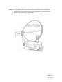
1
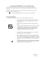
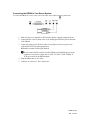
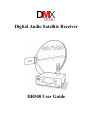
Digital Audio Satellite Receiver DR500 User Guide NOTICE This publication and its contents are proprietary to DMX and are intended solely for the contractual use of its customers for no other purpose than to operate the equipment described herein. This publication and its contents shall not be used or distributed for any other purpose and/or otherwise communicated, disclosed, or reproduced, in any way whatsoever, without the prior written consent of DMX. For the proper operation of this equipment and/or all parts thereof, the instructions in this guide must be strictly and explicitly followed by experienced personnel. All of the contents of this guide must be fully read and understood prior to operating any of the equipment, or parts thereof. FAILURE TO COMPLETELY READ AND FULLY UNDERSTAND AND FOLLOW ALL OF THE CONTENTS OF THIS GUIDE PRIOR TO OPERATING THIS EQUIPMENT, OR PARTS THEREOF, MAY RESULT IN DAMAGE TO THE EQUIPMENT, OR PARTS THEREOF, AND TO ANY PERSONS INSTALLING AND/OR OPERATING THE SAME. DMX does not assume any liability arising out of the application or use of any products, component parts, circuits, software, or firmware described herein. DMX further does not convey any license under its patent, trademark, copyright, or common-law rights nor the similar rights of others. DMX further reserves the right to make any changes in any products, or parts thereof, described herein without notice. © Copyright 1999 Digital Music Express This equipment has been tested and found to comply with the limits for a Class A digital device, pursuant to Part 15 of the FCC Rules. These limits are designed to provide reasonable protection against harmful interference. This equipment generates, uses, and can radiate radio frequency energy and, if not installed and used in accordance with the instructions, may cause harmful interference to radio communications. However, there is no guarantee that interference will not occur in a particular installation. If this equipment does cause harmful interference to radio or television reception, which can be determined by turning the equipment off and on, the user is encouraged to try to correct the interference by one or more of the following measures: • Reorient or relocate the receiving antenna. • Increase the separation between the equipment and receiver. • Connect the equipment into an outlet on a circuit different from that to which the receiver is connected. • Consult the dealer or an experienced radio/TV technician for help. CAUTION: Any changes or modifications not expressly approved by DMX could void the user’s authority to operate the equipment. WARNING Shock Hazard! Do Not Open The DR500 Equipment! Service Only By DMX! Gefährliche Spannung! Öffnen des Gerätes und Service nur durch DMX! The DR500 contains no user-serviceable parts. Do not attempt to service this product yourself. Any attempt to do so will negate any and all warranties. To reduce the risk of fire or electric shock, do not expose this appliance to rain or moisture. CAUTION RISK OF ELECTRIC SHOCK DO NOT OPEN CAUTION: To Reduce The Risk Of Electric Shock, Do Not Remove Cover (Or Back). No User-Serviceable Parts Inside. Refer Servicing To Qualified Service Personnel. Précautions: Pour éviter toute décharge électrique, ne pas enlever le couvercle. Les pieces a l’interieur ne sont pas reparables. Faire appel uniquement á un personnel qualifié. This symbol is intended to alert the user to the presence of uninsulated “dangerous voltage” within the product’s enclosure that may be of sufficient magnitude to constitute a risk of electric shock to persons. This symbol is intended to alert the user to the presence of important operating and maintenance (servicing) instructions in the literature accompanying the appliance. ‘Dolby’ and the ‘Double-D’ symbol are trademarks of Dolby Laboratories Licensing Corporation. AC-3 digital audio system manufactured under license from Dolby Laboratories Licensing Corporation. Table of Contents Introduction Important Information .............................................................................................................. ix Getting Started ......................................................................................................................... ix Section 1: System Overview and Component Descriptions System Features .......................................................................................................................12 What is DMX? .........................................................................................................................12 DBS System Overview.............................................................................................................13 DR500 System Components ....................................................................................................15 DR500 Digital Audio Satellite Receiver ..................................................................15 DR500 Front Panel ...................................................................................15 DR500 Back Panel....................................................................................16 DMR Remote Control Units.....................................................................................17 DMR-22 Remote Control .........................................................................18 DMR-28 DMX/DJ Remote Control..........................................................19 Additional DR500 Receivers....................................................................................................20 Section 2: Installation and Connections Before You Begin ....................................................................................................................20 DR500 Shipment Checklist ..............................................................................................21 Choosing a Good Location.......................................................................................................23 Safety Precautions....................................................................................................................23 Connecting the DR500 to Your Audio System ........................................................................24 Connection Guidelines .............................................................................................24 Connecting the DR500 to Your Stereo System ........................................................25 Connecting the DR500 to Your Monaural System ...................................................26 If the Audio Equipment Has a Direct Digital Coaxial Input.....................................26 Antenna Installation and Alignment.........................................................................................27 Connecting Multiple Receivers to One Antenna ......................................................................28 Recommended Equipment .......................................................................................................28 DR500 (E-4) Rev. C 10/94 Section 3: Getting Started and Basic Operations Section Topics............................................................................................................................1 Starting up the DR500................................................................................................................3 Turning the DR500 ON and OFF...............................................................................................4 Basic Operational Information ...................................................................................................4 Correcting Errors........................................................................................................................5 Checking the Clock ....................................................................................................................5 Setting the Volume.....................................................................................................................5 Muting the Volume ....................................................................................................................6 Selecting a Channel....................................................................................................................7 Front Panel Channel Selection ...................................................................................7 Remote Control Channel Selection ............................................................................7 Recalling a Channel ...................................................................................................................8 Scanning Channels .....................................................................................................................8 DMX/DJ Functions ....................................................................................................................8 Viewing Current Audio Information ..........................................................................8 Viewing the Time.......................................................................................................9 Section 4: Advanced Operations Section Topics............................................................................................................................1 Forced Tune Events....................................................................................................................3 Setting Forced Tune Events........................................................................................3 Checking Forced Tune Events....................................................................................4 Clearing Forced Tune Events .....................................................................................4 Local Channel Management.......................................................................................................5 Deleting Authorized Channels....................................................................................5 Adding Authorized Channels .....................................................................................5 Setting the Dynamic Range........................................................................................................6 Checking Dynamic Range Settings ............................................................................................7 Clearing the Dynamic Range .....................................................................................................7 Setting the Dynamic Range Global Default ...............................................................................7 Setting the Transponder Frequency............................................................................................8 Checking the Transponder Frequency........................................................................................9 Checking Signal Quality ............................................................................................................9 Front Panel Lockout .................................................................................................................11 Setting the Front Panel Lockout ...............................................................................11 Clearing the Front Panel Lockout.............................................................................11 DMX/DJ Functions ..................................................................................................................11 DR500 (E-5) Rev. C 10/94 Checking the DR500’s ID Number ..........................................................................11 Checking the DR500’s Status...................................................................................12 Section 5: Maintenance and Troubleshooting Maintenance ...............................................................................................................................1 Cleaning the DR500 Receiver....................................................................................................1 Troubleshooting Tips .................................................................................................................1 Section 6: Specifications Appendix A: Warranty and Repair Information Warranty Statement ...................................................................................................................................1 Return Procedures DMX Affiliates.......................................................................................................3 Appendix B: DR500 Reference Sheet Appendix C: DR501 User Manual Addendum DR500 (E-6) Rev. C 10/94 Welcome to the world of premier digital audio service provided by DMX. This guide is your handbook for using the DR500 Digital Audio Satellite Receiver and the DMR-22 and DMR-28 DMX/DJ remote control units. The sections in this guide provide step-by-step instructions for a variety of tasks and activities, including DR500 system connections, channel scanning and selection, setting forced tune times and dynamic ranges, and instantaneous viewing of programming information. These exciting options, combined with up to 120 available channels delivering commercial-free, CDquality music, provide you the: • Variety to select music formats that meet your individual business image and needs • Flexibility to create tailored music programs for multiple environments, which you can vary by the hour, day, week, or season • Ability to maintain complete local control over your music Important Information Throughout this guide you will find two symbols designed to help you identify important information. These symbols are: The note identifies information for the proper operation of your equipment, including helpful hints, shortcuts, or important reminders. The exclamation point identifies information that requires careful attention in order to prevent equipment damage and/or injury to the operator. Getting Started Before you begin using the DR500 Receiver, you need to: • Install the DMX/DBS receiver and equipment, which is generally done by your local DMX affiliate or a professional installer. If your DMX/DBS receiver and equipment have not been installed, refer to Section 2: Installation. • Read the appropriate sections of this User Guide as noted below. Do not plug in the DR500 Receiver until you have connected the system and read Section 3: Basic Operations. If you are new to satellite communications or are unfamiliar with either the DR500 or the remote control, you should read the following sections before unpacking or operating this product: • Section 1 for an overview of the DMX/DBS system and equipment • Section 2 helps you get started and contains a full set of DR500 connection procedures • Section 3 for DR500 start-up and basic operations • Section 5 to review maintenance procedures or if you encounter difficulties and need troubleshooting information • Other sections as needed DR500 (E-7) Rev. C 10/94 If you are an experienced user familiar with the DR500 and its remote control, you may wish to review the following sections before unpacking or operating this product: • Section 1 for an overview of the DMX/DBS system and equipment • Section 3 for DR500 start-up and to review basic operations • Section 4 for advanced operations • Appendix E to use the DR500 Reference Sheet • Other sections as needed DR500 (E-8) Rev. C 10/94 DR500 Reference DR500 General Functions and Commands Channel Recall Press LAST. Scan Press SCAN. Select Enter the channel number using the NUMERIC keys. OR Use the TUNEÙ or TUNEÚ keys. Locally Managed Channels Add Tune to the desired channel. Press PRESET 940. Delete Tune to the desired channel. Press PRESET 950. Clock Check Press PRESET 100. Dynamic Range Check Tune to the desired channel. Press PRESET 110. Clear Press PRESET 510. Clears all dynamic range settings from memory. Set Tune to the desired channel. Press PRESET 910. Enter the dynamic range code and press STORE. Global Press PRESET 960. Enter the dynamic range code and press STORE. Forced Tune Events Check Tune to the desired channel. Press PRESET 130. Clear Press PRESET 530. Clears all forced tune event settings from memory. Set Tune to the desired channel. Press PRESET 930. Enter the hour and press STORE. Signal Quality Press PRESET 180. Press any key to clear display. Transponder Frequency Check Press PRESET 120. Set Press PRESET 920. Enter the transponder frequency and press STORE. DR500 (E-9) Rev. C 10/94 DR500 Reference Volume Set Mute Adjust the volume using the controls on your stereo system. Press MUTE. To return to normal volume, press MUTE again. DMX/DJ View Functions and Commands Audio Info. Press Press DR500 Status Press Press Time Press Unit ID Press VIEW. MORE to see additional information. PRESET 150 and press VIEW. MORE to see additional information. PRESET 100 and press VIEW. PRESET 190 and press VIEW. DR500 PRESET Commands and Functions PRESET 100 PRESET 110 PRESET 120 PRESET 130 PRESET 150 PRESET 160 PRESET 180 PRESET 190 PRESET 310 PRESET 510 PRESET 530 PRESET 910 PRESET 920 PRESET 930 PRESET 940 PRESET 950 PRESET 960 PRESET 970 PRESET 975 Check the DR500 clock. Check the dynamic range for a selected channel. Check transponder frequency. Check the forced tune event for a selected channel. Check status of DR500. Toggle LNB Power Supply On/Off. Check the signal quality. Check DR500 Unit ID Number. Toggle Generation of Pink Noise On/Off. Clear all dynamic range settings from memory. Clear all forced tune event settings from memory. Set the dynamic range for a selected channel. Set transponder frequency. Set the forced tune event for a selected channel. Add authorized channels. Delete authorized channels. Set global dynamic range. Front panel lockout. Volume control. DR500 (E-10) Rev. C 10/94 Thank you for subscribing to Digital Music Express! This section describes the Direct Broadcast Satellite (DBS) receiver and equipment that are used to deliver the best in CD-quality music. The equipment includes: • Satellite dish receiving antenna, low noise block (LNB) amplifier, and connecting cable • Digital Audio Satellite Receiver, Model DR500 • Remote control device, Model DMR-22 or Model DMR-28 DMX/DJ DR500 (E-11) Rev. C 10/94 System Features The DR500 DBS Satellite Receiver is a digital audio stereo decoder which easily integrates with most stereo or monaural amplifier systems. Key system features include: • Full CD quality 20 kHz stereo • 120 stereo pairs available on one transponder • Dolby Digital compression • Storecasting and datacasting capabilities • User and network programmable forced tune events (dayparting) • Exclusive DMX/DJ IR remote provides artist, album, and title information • Multi-zone expansion capabilities • Utilizes a small, one-meter satellite dish in most CONUS locations • Digital audio output, Sony/Philips Digital Interface Format (SPDIF) To fully appreciate the DMX/DBS service, you must have a separate stereo system that can be connected to the DR500. (For information on connecting the system, refer to “Connecting the DR500 to the Audio System” found in Section 2: Installation and Connections. What is DMX MUSIC? DMX MUSIC is an innovative music programming service that delivers up to 120 channels of CD-quality, commercial-free music via satellite transmission. To provide you with this unparalleled digital sound service, DMX MUSIC uses the latest satellite technology to deliver DMX/Direct Broadcast Satellite (DBS) music to your location. DR500 (E-12) Rev. C 10/94 DBS System Overview Although the use of satellites, satellite dishes, and receivers may seem complex, the DMX/DBS service uses a highly sophisticated system that makes channel selection and local music programming easier and simpler than using a VCR. It also allows DMX to deliver music of unprecedented linearity, sonic precision, and exceptional fidelity. The DMX/DBS premiere digital audio service uses the following satellite technology: • Satellite Uplink Facility transmits music programming to the satellite through satellite dishes • Satellite relays the music programming signals to your satellite dish antenna • DBS Satellite Dish Antenna receives the music programming transmitted from the satellite and relays it to the DR500 Receiver. Your satellite dish can be as small as one meter and may be installed in various places on or around your location. The only constraint is that the satellite dish must be properly pointed at the satellite with no obstacles blocking the satellite signal. DR500 (E-13) Rev. C 10/94 Once the DMX music programming is received at your location, your DR500 Receiver and associated audio components take over. • COMSTREAM DR200 Digital Audio Receiver DIGITAL AUDIO DR500 Digital Audio Satellite Receiver receives and decodes the digital audio programming information and sends it to your stereo amplifier system Additional DR500 receivers provide you with additional flexibility to create tailored music programs for multiple business environments that you can vary by the hour. Additional units can be integrated into your system at any time. • 1 2 3 4 5 6 8 9 7 0 Remote Control device allows you to control and program the DR500 Receiver and DBS system There are two available remote control devices: the DMR-22, which is a basic remote control device, and the DMR-28 DMX/DJ, which provides additional programming information and functionality. DR500 (E-14) Rev. C 10/94 DR500 System Components The DR500 Digital Audio Satellite Receiver is a digital audio stereo decoder that easily integrates with most stereo or monaural amplifier systems. DR500 Digital Audio Satellite Receiver The DR500 is the master receiver that connects to the satellite dish and your stereo or monaural amplifier system. DR500 Front Panel The front panel of the DR500 is used to turn the DR500 on and off and manually select music channels. The front panel consists of: • Power selector turns the DR500 on and off When the DR500 is Off, a small green light appears on the front panel, indicating that the DR500 is able to receive any information from the DMX/DBS National Authorization Control Center. • Music channel selectors allow you to tune to the next higher Ù or lower Ú channel If remote channel selection is preferred, use either the DMR-22 or DMR-28 DMX/DJ Remote Controls. • Front panel display shows the current channel selection as well as other DR500 information • Stereo/Mono A/Mono B indicators - illuminates green to indicate either a stereo channel, or one of two mono subchannels. • Sync indicator illuminates green when the DR500 Receiver has locked onto the satellite • Authorized indicator illuminates green when you are authorized to receive the current channel • LNB PWR illuminates green to indicate LNB power is enabled. No illumination indicates LNB power is disabled. Blinking indicates a problem with the LNB power supply. (For more information, refer to Section 5: Maintenance and Troubleshooting.) DR500 (E-15) Rev. C 10/94 DR500 Back Panel The back panel of the DR500 has a variety of connectors that are used to link the satellite dish to the DR500 and your audio system to the DR500. The back panel consists of: • Power Input attaches the DR500 to a 120 VAC wall mount supply • RF IN connector attaches the DR500 Receiver to your local satellite dish • Mono Out connector attaches the DR500 to a monaural receiver or amplifier • Stereo Out connectors attaches the DR500 to a stereo receiver or amplifier. Left is coded white; right is coded red. • Digital Out connector (standard Sony/Philips Digital Interface Format [SPDIF] coaxial output; coded black) attaches the DR500 to a digital input of audio equipment that has a coaxial digital input. • Data/Control connector for PC control and diagnostics • Serial ID number/bar code label — lists the serial number for this unit DR500 (E-16) Rev. C 10/94 DMR Remote Control Units To select music channels remotely, you can use either the DMR-22 or DMR-28 DMX/DJ remote control units. Both remote control models have the following features: • Individual channel selection keys that allow you to move through the authorized channels one channel at a time either up or down • Preset channel selection key that allows you to enter special music programming information • Scan key that allows you to step through each authorized channel, each playing for five seconds • Mute function that allows you to turn the audio on and off • Last channel recall function that allows you to return to the previously selected channel To use either remote control unit, point it toward your DR500 Receiver and press the appropriate keys. The remote control units can be used at distances of up to 10 meters (32 feet) while you are directly in front of and in a straight line to the DR500 Receiver. Communication between the remote control and DR500 will be impaired if there are obstructions blocking the transmission or if the remote control is not directed straight at the DR500. If the remote control fails to operate, refer to Section 5: Maintenance and Troubleshooting. DR500 (E-17) Rev. C 10/94 DMR-22 Remote Control The DMR-22 remote control unit is described below. Use with the number keys to store a preset entry MUSIC POWER ID STORE Turns the DR200 on and off 1 2 PRESET Use to enter special settings 3 TUNE Tune to any channel 4 5 6 7 8 9 TUNE TV Recalls your last channel selection MUTE 0 SCAN LAST VOL VOL Tunes to the next higher authorized channel Tunes to the next lower authorized channel Steps through your authorized channels (each plays for five seconds) Mutes the audio Turns the volume up Turns the volume down Only the keys indicated operate the DR500 Receiver. The other remote control keys have no DR500-associated functions. DR500 (E-18) Rev. C 10/94 DMR-28 DMX/DJ Remote Control In addition to the basic features, the DMX/DJ provides instant viewing of the following information for each music selection: • Title • Album • Composer • Artist • Record label • Album ID number The DMX/DJ also displays DR500 operation information, help messages, and low battery indication. The DMX/DJ remote control is described below. DMX/DJ LCD display shows operations, DMX program information, help messages, and low battery indicator Use with the number keys to store a preset entry Selects DMX mode for DR200 control Turns the DR200 on and off MODE Retrieves DMX program title and other information TITLE CABLE DMX POWER BUY POWER ID MENU VIEW MORE SLEEP FAVORITE STORE PRESET SELECT DISPLAY TV SCAN Music ID (future use) Tunes to any authorized channel, and up to ten preset channels 1 2 3 TUNE 4 5 6 TUNE 7 8 9 LAST Mutes the audio VOL Use with the number keys to enter preset commands Steps through your authorized channels (each plays for five seconds) Tunes to the next higher authorized channel Tunes to the next lower authorized channel 0 MUTE Scrolls through additional DMX program information VOL Recalls your last channel selection Turns the volume up Turns the volume down The DMX/DJ must be in DMX mode (press the DMX key) to enter commands and operate the DR500 Receiver. When the DMX/DJ is in DMX mode, DMX appears in the remote's display. The volume control keys on the remote control may be inactive or off. To make these keys active, press PRESET 975. Only keys indicated operate the DR500. Other keys have no DR500-associated functions. DR500 (E-19) Rev. C 10/94 Additional DR500 Receivers Additional DR500 receivers can be added to your system at any time. Each receiver allows you to select and play one different DMX music channel on a separate audio system. This provides additional stereo music channels to cover other locations or zones. Two or more DR500 Receivers may be connected to one antenna to provide different music channels via separate audio systems. For additional information regarding the connection of multiple receivers to one antenna, refer to Section 2. DR500 (E-20) Rev. C 10/94 This section helps you set up and connect your DR500 system. It provides: • DR500 shipment checklist • Tips on selecting the best location for your system • Step-by-step instructions for connecting the DR500 Receiver to your audio system Before You Begin Before you begin using your DR500, it is assumed that the DMX/DBS receiving equipment has been professionally installed, which includes: • Setting up the satellite dish and its LNB, correctly positioning the dish so that it is pointed at the satellite, and connecting it to the DR500 Receiver (For additional information, refer to Appendices B and C.) • Placing batteries in the remote control unit to allow remote control operation DR500 (E-21) Rev. C 10/94 DR500 Shipment Checklist The DR500 and its components are shipped in custom-designed, reinforced cardboard cartons. To ensure that the system is protected during opening, use a cutting tool that extends less than ½ inch into the carton. Keep the carton and original packaging to return a unit for repair, in the unlikely event of a failure. After the carton is opened, carefully remove the DR500 and all system components and check the following items: Visually inspect the system to ensure that no physical damage has occurred during shipping. Verify that all standard items were received. Standard items include: • One DR500 Digital Audio Satellite Receiver • One Wall Mount Power Supply • One stereo cable (RCA plug type, approximately one meter long) • This User Guide DR500 (E-22) Rev. C 10/94 Choosing a Good Location There are a few items to consider when selecting a location for your DR500 Receiver. Observe the following Safety Precautions: Safety Precautions Carefully read and follow all safety, use, and operating instructions before operating the DR500. Heed all warnings and cautions contained in this User Guide. Retain these safety, use, and operating instructions for future reference. FOLLOW STARTUP PROCEDURE Do not plug in the DR500 Receiver until you have connected the system and read Section 3: Basic Operations. PROVIDE A SAFE LOCATION Place the DR500 on a stable surface of sufficient size and strength, where it will not be jarred, hit, or pushed off its surface. Ensure that all cables and cords are out of the way and will not be tripped over, as this could cause personal injury or serious damage to the DR500. AVOID WATER AND MOISTURE Do not expose the DR500 to any liquids, which are often found in flower vases, coffee cups, rain from open windows, etc. If the DR500 is exposed to any liquid, contact your DMX affiliate, as serious damage could occur to the DR500 or its components. AVOID HEAT, HUMIDITY, AND DUST To avoid internal damage, the DR500 should be placed away from all heat sources, including radiators, heater ducts, etc., out of direct sunlight, and away from high humidity, excessive dust, or mechanical vibrations, that can cause damage to internal parts. PROVIDE ADEQUATE VENTILATION To avoid overheating, place the DR500 on a smooth, hard surface that has 2" of clearance around the unit and adequate air circulation. If the DR500 is placed in a closed area, such as a bookcase or rack, ensure that proper ventilation is provided. Never place the DR500 on a soft surface, such as a rug, sofa, or bed, that would obstruct the required air flow into the DR500 ventilation slots. USE CORRECT POWER SOURCE Operate the wall mount power supply for the DR500 from a 120 V, 60 Hz outlet only. Take care not to overload wall outlets or extension cords, as this increases the risk of fire or electrical shock. ROUTE POWER CORDS SAFELY Route power cords so they are not walked on or pinched. Pay particular attention to cords and connections at the plugs, receptacles (such as power strips), and the point where they exit from the DR500 and attach to other equipment. Do not place any items on or against power cords. USE APPROVED ATTACHMENTS ONLY Use only DMX-approved attachments with the DR500 Receiver.. DR500 (E-23) Rev. C 10/94 Connecting the DR500 to Your Audio System If your DR500 system has not been professionally installed, if you have disconnected your DR500 Receiver, or if you are adding a component, refer to the following steps and diagrams to help you connect your system. If you have questions or need assistance connecting any components to your DR500, please contact your DMX MUSIC Affiliate Sales Support team. To connect multiple DR500 Receivers to one antenna, refer to Appendix D. Connection Guidelines It is important that you follow these guidelines when making any DR500 system connection: • Do not plug the Receiver into an AC outlet until all connections have been made and you have read the Startup procedures in Section 3: Basic Operations. • Turn the audio system amplifier OFF and the volume completely down. • • Connections should be finger-tight only; never use pliers or a wrench. The DR500 Receiver wall mount power supply is not polarized, and any orientation on the wall or power strip is acceptable. When mounting to a standard dual outlet, a screw is provided to prevent accidental removal of the wall mount power supply. • The DR500 Receiver should not be plugged into an AC socket like those found on the rear of audio amplifiers. • Once the DR500 is connected, turned on, and receiving the satellite signal, it should remain plugged in to an unswitched (on) AC outlet so that it can receive any programming updates, authorization commands, and information from the DMX/DBS National Authorization Control Center. If the DR500 will not be used for extended periods of time, it should be turned off using the front panel power switch only. It should not be unplugged nor have its AC power turned off. DR500 (E-24) Rev. C 10/94 Connecting the DR500 to Your Stereo System To connect the DR500 to a stereo system, refer to the figure below and the following instructions. 1. Make sure the stereo amplifier is OFF and the volume is turned completely down. 2. Connect the RCA stereo cables to the L(eft) and R(ight) STEREO jacks on the back of the DR500. 3. Connect the other end of the RCA cables to any high-level input on your stereo equipment EXCEPT the phonograph input. Remember to match left and right channels. Do not connect the RCA cables from the DR500 to the PHONO input of audio equipment. Any line level input such as AUX, CD, DAT, TAPE, VIDEO, or VCR can be used for the DR500 output. 4. Plug the DR500 into an AC outlet. 5. Continue on to Section 3: Basic Operations. DR500 (E-25) Rev. C 10/94 Connecting the DR500 to Your Monaural System To connect the DR500 to a monaural system, refer to the figure below and the following instructions. 1. Make sure the monaural amplifier is OFF and the volume is turned completely down. 2. Connect an RCA cable to the MONO jack on the back of the DR500. 3. Connect the other end of the RCA cable to any available input on the monaural equipment EXCEPT the phonograph input. Do not connect the RCA cables from the DR500 to the PHONO input of audio equipment. Any line level input such as AUX, CD, DAT, TAPE, VIDEO, or VCR can be used for the DR500 output. 4. Plug the DR500 into an AC outlet. 5. Continue on to Section 3: Basic Operations. If the Audio Equipment Has a Direct Digital Coaxial Input To connect the DR500 to audio equipment with direct digital input, refer to the figure below and the following instructions. Connect a shielded RCA cable (not provided) from the DIGITAL OUT connector on the DR500 to the coaxial DIGITAL INPUT connector on the audio equipment. (See your stereo manual for specific requirements.) The default output format is uncompressed PCM; it may optionally be configured as Dolby Digital. DR500 (E-26) Rev. C 10/94 Antenna Installation and Alignment It is recommended that the Satellite dish antenna be installed by your local DMX Affiliate. It is imperative that the dish be securely and safely mounted, and pointed accurately at the Satellite. Brief instructions are presented here for completeness. Satellite Dish Installer: Ground the RF input cable to the building grounding system as close as possible to the point of building entry. Refer to the National Electric Code (NEC) Article 820-40. The following steps describe the process to properly set up, position, and connect the antenna using the DR500 Receiver: 1. Determine the proper block converter and feed horn polarity adjustment for your area. 2. Assemble the satellite dish antenna. 3. Locate the antenna in an area with an unobstructed line of sight to the satellite coordinates (azimuth and elevation) for your area. For information relating to satellite location and coordinates, antenna alignment, and signal acquisition, contact your DMX affiliate. 4. Pre-position the antenna to the correct azimuth and elevation coordinates by using a compass and inclinometer. 5. Pre-position the LNB to the indicated polarity setting. 6. Locate the DR500 Receiver within visual range of the antenna. 7. Connect a 75 ohm coaxial cable (RG-6, typical) from the output of the LNB to the Receiver RF IN connector. 8. Connect 120 VAC power to the DR500 Receiver – do not turn it on. Improvise a temporary sun shade over the DR500 front panel as the LED displays may be difficult to read in direct sunlight. 9. Place the receiver in signal strength mode by depressing the power, channel up, and channel down buttons simultaneously. Alternatively, this may be done with the remote control using Preset 180. − The display reads nL, signifying it is not locked. – Channel 1 flashes on the front panel display indicating the receiver is muted – AUTH LED is Off unless the receiver is already authorized – SYNC LED is Off and remains so until the satellite is acquired The signal strength level numbers are preceded by a minus sign (-) to differentiate them from a music channel number. Signal Quality readings vary from -00 (the strongest level) to approximately -80 (weakest level) before losing the satellite lock nL. Rock the dish slowly from side to side and up/down around the nominal position. When the Satellite has been located, the display will read out a negative number representing signal strength and the Sync light will illuminate. Carefully move the dish to maximize signal, at which time the readout will be the least negative (closest to zero). Tighten the bolts and check that signal strength has not been disturbed by tightening the bolts. DR500 (E-27) Rev. C 10/94 Connecting Multiple Receivers to One Antenna Multiple DR500 Receivers can be connected to one antenna. However, to avoid damage to either the antenna LNB and DR500 Receiver, the following items must be used: • Correct splitter(s) • Proper line amplifiers Line amplifiers may be required when using a signal splitter and/or when long coaxial cable runs are required from antenna to receiver. All splitters and line amplifiers should be rated for satellite IF processing with a minimum bandwidth of 950 MHz to 1450 MHz. Since power is delivered to the LNB and line amplifier by the DR500 Receiver (18 VDC via RF IN connector), splitters should have one DC power passing port. All other ports must block DC or have equivalent circuitry that only permits one of the DR500 Receivers to power the LNB. Never connect via power passing splitters. Additionally, the receivers not delivering power to the LNB should have their LNB power output switched OFF using Preset 160. Failure to do so may result in severe damage to the antenna LNB and the DR500 Receivers The line amplifier should be inserted just prior to the input of the splitter (not after the antenna LNB). For best performance line amplifiers are typically inserted every 150 feet. Recommended Equipment The following equipment is recommended when multiple receivers are connected to one antenna: • • High frequency splitters − QINTAR HFS-2 and HFS-4. Two and four port splitters that pass power from one port. − QINTAR HFS-2WB and HFS-4WB. Two and four port 5 to 2050 MHz wide band splitters with a built in zener diode circuit to protect DC return back to the DR500 Receiver. These splitters can be used in installations requiring power passing to only one port. In-line satellite amplifier − • QINTAR LA-2050. This line amplifier has a bandwidth of 10 to 2050 MHz. It is typically powered by the DR500 Receiver 18 VDC power. Coaxial Cable − For short runs, under 150 feet, use a 75 ohm RG-59 coaxial cable. − For cable runs over 150 feet, use higher quality RG-6 or RG-11 cable to minimize antenna signal loss and amplifier requirements. DR500 (E-28) Rev. C 10/94 The DR500 advanced features give you the power and flexibility to create tailored musical programs. These advanced functions include: • Forced tune programming a channel is automatically selected and played at a specific time • Adding and deleting authorized channels • Setting the dynamic range of a particular channel or all channels useful when DMX selections are playing in a noisy environment Section Topics This section describes the advanced functions and operation of the DR500 and remote control. Advanced functions include: • Setting, checking, and clearing forced tune events • Local channel management • Setting and checking the Dynamic Range for individual channels and as a global default • Setting and checking transponder frequency • Setting and clearing the front panel lockout • DMX/DJ functions Many of these features can be programmed and controlled by the DMX DBS National Authorization Center. When you turn on your DR500 and call for authorization, talk to your DMX affiliate about this service. DR500 (E-29) Rev. C 10/94 Forced Tune Events Forced Tune Events allow you to easily specify at what hour a particular channel will be played. Although forced tune events sound simple, they’re actually a powerful function that provides you with a wide range of musical programming flexibility and creativity, along with local manageability. Setting Forced Tune Events The DR500 allows you to program and store up to six forced tune events per day. These forced tune events can be programmed for one channel or spread across a maximum of six channels. To set a forced tune event: 1. Tune to the desired channel. 2. Press: PRESET 9 3 0 The front panel displays two flashing zeros, indicating that the DR500 is ready for you to enter the hour to tune in this channel. You specify forced tune events for the hour, on the hour (10, 11, etc.). You cannot specify a portion of an hour, such as 10:15 a.m. If you need a forced tune event to play at a specific hour and minute, contact the DMX/DBS National Authorization Control Center who will program the event for you. 3. Enter the hour in 24-hour format then press STORE. # # STORE For example, 8:00 p.m. would be entered as 20. If there are less than six forced tune events programmed, the new event will be stored in memory. At the designated time, the DR500 will automatically tune to the programmed channel. If you exceed the six forced tune events maximum, the DR500 front panel displays FUL (full) indicating the memory is full. When FUL displays, the DR500 memory must be cleared before any forced tune events can be entered. Refer to Clearing Forced Tune Events for this procedure. Pressing PRESET while entering a forced tune event exits the procedure and returns to the current channel. If two forced tune events are inadvertently scheduled for the same time period, the event that was set first will play. Checking Forced Tune Events To check the forced tune event settings for a channel: 1. Tune to the desired channel. 2. Press: PRESET 1 3 0 DR500 (E-30) Rev. C 10/94 If the current channel has no programmed forced tune events, the front panel displays three flashing dashes. If the current channel has any programmed forced tune events, the time of the event (in 24-hour time) displays on the front panel as a flashing two-digit number. If more than one event is programmed for the channel, the front panel will scroll through all programmed events, displaying each for five seconds. Once all the forced tune events have been displayed, the front panel returns to the current channel. Clearing Forced Tune Events The DR500 allows you to program and store up to six forced tune events. These forced tune events can be programmed for one channel or spread across a maximum of six channels. If you have exceeded the six forced tune events maximum, the DR500 front panel displays FUL indicating the memory is full. When FUL displays, the DR500 memory must be completely cleared before new forced tune events can be entered. To clear the DR500 memory press: PRESET 5 3 0 The front panel will momentarily display CLr (clear) as the DR500 clears all forced tune events from memory. When the DR500 has finished clearing all settings, the current channel displays. DR500 (E-31) Rev. C 10/94 Local Channel Management The DR500 allows you to locally manage the channels authorized to you through DMX/DBS National Authorization Control Center. From your location, you can temporarily delete an authorized channel so that it cannot be played for a specific time in your location. Then, when you decide the timing is right, you can add the authorized channel into your format again. Deleting Authorized Channels The DR500 gives you local control to delete channels from your list of authorized channels. To locally delete an authorized channel: 1. 2. Tune to the desired channel. Press: PRESET 9 5 0 The front panel flashes dEL (delete) as the DR500 marks the channel as locally deleted. In addition: • Authorization LED remains ON as this a locally deleted channel • Audio is muted for that locally deleted channel • dEL flashes on the DR500 display when this channel is selected Adding Authorized Channels Just as you can locally delete an authorized channel from your local channel listing, you can also add the channels back to the list. To do this: 1. Tune to the desired channel. 2. Press: PRESET 9 4 0 The front panel momentarily displays Add as the DR500 adds the authorizes channel. In addition: • Channel you added is displayed • Authorization LED remains ON • Audio is broadcast from that locally added channel You locally manage only channels authorized by your DMX affiliate. To add authorized channels to your local listing, contact your DMX affiliate. DR500 (E-32) Rev. C 10/94 Setting the Dynamic Range The DR500 Receiver is shipped with all 120 channels set at full CD-quality (90 dB dynamic range). To meet your individual music needs, you have the capability of setting a different dynamic range for up to 10 channels, or setting all channels to a global dynamic range default. Changing the dynamic range setting may provide a more uniform volume, or loudness, throughout your musical program. To set the dynamic range for a channel: 1. 2. Tune to the desired channel. Press: PRESET 9 1 0 The front panel flashes the current dynamic range code for this channel. The range codes are: Front Panel Code Remote Control Code Dynamic Range Settings 00 00 Full CD-quality (90 dB) 01 01 80 dB range 02 02 60 dB range 03 03 40 dB range 3. Enter the dynamic range code. Press the appropriate number (or use the TUNEÙ and TUNEÚ buttons to make your selection), then press STORE. # STORE If there are less than 10 Dynamic Range settings programmed, the new setting will be stored in memory. The DR500 will automatically implement the selected dynamic range when the specified channel is tuned. If you have exceeded the 10-channel maximum, the DR500 front panel displays FUL indicating the memory is full. When FUL displays, the DR500 memory must be completely cleared before additional Dynamic Range settings can be entered. Refer to Clearing the Dynamic Range for this procedure. Pressing PRESET while entering a Dynamic Range code exits the procedure and returns the display to the current channel. Dynamic range settings specified for individual channels will override, or take precedence over, global dynamic range default settings. DR500 (E-33) Rev. C 10/94 Checking Dynamic Range Settings To check the dynamic range for a specific channel: 1. Tune to the desired channel. 2. Press: PRESET 1 1 0 The front panel flashes the current dynamic range code (00-03) for this channel. If a specific dynamic range has not been set, the front panel displays a flashing three-digit number representing the global default for that channel. Clearing the Dynamic Range The DR500 allows you to program and store up to 10 channels with specific dynamic range settings. If you have exceeded the 10-channel maximum, the DR500 front panel displays FUL indicating the memory is full. When FUL displays, the DR500 memory must be cleared before additional dynamic range settings can be entered. To clear the DR500 memory, press: PRESET 5 1 0 The front panel will momentarily display CLr as the DR500 clears all dynamic range settings from memory. When the DR500 has finished clearing all settings, the current channel displays. Setting the Dynamic Range Global Default To set one dynamic range for all authorized channels: 1. Press: PRESET 9 6 0 2. Enter the dynamic range code. Press the appropriate number (or use the TUNEÙ and TUNEÚ buttons to make your selection), then press STORE. # STORE All channels are set to the specified dynamic range. To change or clear the global dynamic range default setting, repeat this procedure. DR500 (E-34) Rev. C 10/94 Setting the Transponder Frequency The DR500 is shipped with the transponder frequency saved in memory. It is highly unlikely that this frequency will have to be changed and should only be done upon instructions from your DMX affiliate. In the event that a new transponder frequency must be entered, follow these procedures: 1. Press: PRESET 9 2 0 The transponder frequency in MHz displays as a flashing three-digit code on the front panel. The transponder frequency codes and their corresponding frequencies are shown below. MHz Front Panel Codes Transponder Frequency 950 to 999 950 MHz to 999 MHz 000 to 450 1000 MHz to 1450 MHz 2. Enter the transponder frequency using the DR500 front panel codes. (For example, you enter a frequency of 1249 MHz using the code 249.) Press the appropriate number, then press STORE. # # # STORE The new transponder frequency will be stored in memory. Pressing PRESET while entering a Transponder Frequency code exits the procedure and returns to the current channel. Be careful to enter the correct frequency. The DR500 will not operate if the Transponder Frequency is incorrect. DR500 (E-35) Rev. C 10/94 Checking the Transponder Frequency To check the current transponder frequency, press: PRESET 1 2 0 The front panel flashes the current Transponder Frequency MHz code. Checking Signal Quality The quality of the incoming signal can be checked using the following procedures: 1. Ensure that the DR500 has acquired the signal the sync indicator on the front panel will be lit. 2. Press: PRESET – 1 8 0 The front panel displays SS (signal strength) and then displays a dash followed by a two-digit number from 00 to 99 indicating the strength of the incoming signal. # # The display is updated approximately twice per second. Your display may not change if the signal quality is constant. – If the DR500 is not locked, nL displays on the front panel. Unlike most other DR500 functions, the signal quality indicator does not automatically clear from the display. To clear the display, press any key on the remote control or the DR500 front panel. DR500 (E-36) Rev. C 10/94 The following table shows the DR500 codes and their corresponding Eb/No levels. A code of -00, with a corresponding Eb/No level of 17 dB or greater, is the highest signal quality. A code of -68, with corresponding Eb/No levels of 5 dB or lower, is a very weak signal strength. DR500 Display Code Eb/No Signal Strength -00 to -01 17+ dB -02 16 dB -04 15 dB -06 14 dB -09 13 dB -14 12 dB -20 11 dB -27 10 dB -35 09 dB -44 08 dB -52 07 dB -61 06 dB -68 05 dB -75 04 dB -80 03 dB nL not locked DR500 (E-37) Rev. C 10/94 Front Panel Lockout Setting the Front Panel Lockout The DR500 allows you to inhibit, or lockout, any command entries. To do this press: PRESET 9 7 0 The front panel displays LOC indicating that the front panel has been locked. When the front panel has been locked, both the front panel and the remote control will be non-functional. The only command that will be accepted by the DR500 is the command to clear the front panel lockout. Clearing the Front Panel Lockout To clear the front panel lockout, press: PRESET 9 7 0 STORE The front panel lockout command will be cleared and the DR500 will receive all commands through the front panel and be fully functional again. DMX/DJ Functions Checking the DR500’s ID Number Every DR500 Receiver has a specific identification (ID) number which is located on the back of the DR500. To check the DR500’s ID number using the DMX/DJ, press: PRESET 1 9 0 VIEW The ten-digit ID number displays in the following format: • ID NUMBER 123-4567-890 DR500 (E-38) Rev. C 10/94 Checking the DR500’s Status You can periodically check the status of the DR500 using the DMX/DJ. 1. To check the status, press: PRESET 1 5 0 VIEW The DMX/DJ displays a variety of status messages. 2. To move through the screens of information, press MORE on the DMX/DJ. MORE The DR500 status messages are presented in the following tables. DMX/DJ General Status Messages Status Message Description SIG STRENGTH: ## Displays the Eb/No signal strength. For a listing of signal strength codes, refer to Signal Quality. USER DELETED: ## Displays the number of authorized channels that the user locally deleted. USER DYN RNG: ## Displays the number of channels that have a dynamic range setting. USER FORCED TN: ## Displays the number of programmed forced tune events. FREQ: ##kHz Displays the RF frequency. DR500 V#.## Displays the current DR500 software version. DR500 (E-39) Rev. C 10/94 Front Panel Status Code DMX/DJ Status Message DR500 Status Individual Error Messages 000 System OK DR500 is working properly 001 System PLL Phased locked loop error 002 System LNB Power to the low noise block (LNB) is shorted 004 System NV Nonvolatile memory errors Combined Error Messages 003 System PLL System LNB Phased locked loop error and power to the low noise block (LNB) is shorted 005 System PLL System NV Phased locked loop error and nonvolatile memory errors 006 System LNB System NV Power to the low noise block (LNB) is shorted and nonvolatile memory errors 007 System PLL System LNB System NV All system errors are detected For additional information about DR500 status messages, refer to Section 5: Maintenance and Troubleshooting. Maintenance The DR500 Receiver and remote controls are designed to deliver years of maintenance-free, CD-quality music. The only maintenance you may need to perform is cleaning your DR500 Receiver and replacing batteries in your remote control. Cleaning the DR500 Receiver Before cleaning the DR500, unplug it from the wall outlet. Clean the cabinet, panel, and controls with a soft cloth lightly moistened with water. Do not use any type of abrasive pads, scouring powders, liquid cleaners, aerosol cleaners, or solvents such as alcohol or benzene. DR500 (E-40) Rev. C 10/94 Troubleshooting Tips The troubleshooting tips found on the following pages were designed to help you diagnose and correct minor problems in the unlikely event that you experience difficulties with your DBS DR500 system. Possible problems, arranged alphabetically, are followed by solutions that should help you to troubleshoot any DBS DR500 difficulties. If you try all the suggested solutions and nothing works, call your DMX affiliate, as they are equipped to diagnose and correct your DBS system and DR500 Receiver problems. Problem Possible Causes Solutions Authorized indicator is NOT lit green You are not authorized to receive the current channel. Tune to an authorized channel. Contact your DMX affiliate if you wish to receive the music channel. DR500 Receiver does not work DR500 is not plugged in. Check that the DR500 is plugged into an AC power outlet. The AC outlet is off. Turn the AC outlet on. The AC outlet is not working. Switch the DR500 power cord to another outlet. Have a professional electrician check the outlet. The AC outlet is not providing the required power. (You may be experiencing a power brown out in your area.) Operate the DR500 from a 120 V, 60 Hz outlet only. Have a professional electrician check the outlet. The DBS system is not correctly installed, the satellite dish antenna is not pointed at the satellite. Check the DBS system for proper operation and that the satellite dish is in the correct position (refer to Section 1). DR500 Receiver shows a distinct change in operation or is not operating normally The DR500 may need to be serviced. Unplug the receiver from the wall outlet. Wait 30 seconds. Plug the DR500 back into the outlet. Check the DR500’s performance. If the DR500 still performs poorly, contact your DMX affiliate. LNB PWR Indicator Flashing The cable connecting the DR500 to the satellite Disconnect the cable from the unit and dish is shorted. wait 30 seconds. If the Fault light turns off, replace the cable. If the Fault light flashes, contact your DMX affiliate. There is a problem with the satellite dish LNB. Contact your DMX affiliate. Music stops briefly or is distorted The audio signal for the particular music channel was temporarily interrupted by a technical problem. Select another music channel or wait for the music to begin again. Poor satellite signal quality sometimes due to sunspots or inclement weather. Wait for the music to begin again. If this is a frequently re-occuring problem, contact your DMX affiliate. The DR500 was subjected to excessive vibration or movement. Ensure that the DR500 is in an appropriate location away from vibration or movement that may cause the music to stop momentarily. DR500 (E-41) Rev. C 10/94 Problem No sound Possible Causes Solutions The stereo is turned off or the volume is turned Turn on the stereo and adjust the volume. down. The DR500 Receiver volume is turned down. Turn the volume up on the DR500 Receiver. The Mute function is selected. To return to normal volume, press MUTE on your remote control. You are not authorized to receive the current channel. Tune to an authorized channel (refer to Section 3). Contact your DMX affiliate if you wish to receive the music channel. The DR500 and stereo connectors are not correctly attached. Check all DR500 and stereo connections. No sound from one speaker Balance is incorrectly set or stereo/speaker connections are not correctly adjusted. Adjust the balance controls on your stereo and check all connectors. Remote control does not operate the DR500 The remote control is not pointed at the DR500. Point the remote control directly at the DR500. Ensure that there are no obstacles between the DR500 and the remote control unit. The remote control is too far from the DR500. Move to within 10 meters of the DR500. The path between the DR500 and remote control is obstructed. Remove the obstruction, point the remote control directly at the DR500. The DMX/DJ mode is not set to the correct mode. Ensure that the DMX/DJ mode is set correctly. You will see DMX appear on the DMX/DJ display (refer to Section 1). Front panel lockout is set. Unlock the front panel (refer to Section 4). The remote control batteries are run down. Replace all remote control batteries. Remote control is broken. Check that the remote control is functioning properly by performing the procedure for viewing the time on the DMX/DJ. DR500 (E-42) Rev. C 10/94 Problem Remote control operates erratically Possible Causes The remote control is exposed to direct, bright sunlight or florescent lighting. This exposure may interfere with the remote control signal and not allow the remote and DR500 to communicate. Protect the remote control from the direct light exposure. Remote control is broken. Check that the remote control is functioning properly by performing the procedure for viewing the time on the DMX/DJ. Sync indicator is not lit Poor satellite signal quality sometimes due to green sunspots, rain, or other inclement weather. Volume control does not work Solutions Wait for the weather to clear. The DR500 Receiver has not locked onto the satellite. Check the alignment of the satellite dish (refer to Section 1). Unplug the receiver from the wall outlet. Wait 30 seconds. Plug the DR500 back into the outlet. Check the DR500’s performance. If the DR500 still performs poorly, contact your DMX affiliate. Power to the low noise block (LNB) amplifier is shorted or set to OFF. Check LNB PWR indicator. If it is not illuminated, power to the LNB is OFF. This may be normal for multiple receiver installations provided signal from a single LNB. Contact your DMX affiliate before switching LNB to ON. Power is disconnected to the low noise block (LNB) amplifier. Check the cable. Volume control keys are off. Turn the volume control keys on, use PRESET 975. DR500 (E-43) Rev. C 10/94 Audio Specifications* Compression: Dolby Digital Sampling Rate: 44.1 kHz Frequency Response: 20.0 Hz to 20.0 kHz ±1.0 dB Dynamic Range: >90 dB Harmonic Distortion: < 0.015% typical, 0.05% maximum Output Level 0-2 V rms (maximum) Tuner Specifications* Input Frequency: 950 to 1450 MHz Input Dynamic Range: -20 dBm to -65 dBm LNB Power: 250 milliamps max 18 VDC ±10% LNB Frequency Drift: ±5 MHz Audio Threshold: 5.1 dB Eb/No for 10-5 BER General Specifications* Power Supply: 100-130 VAC, 60 Hz Power Consumption: 20 Watts maximum Operating Temperature: 0° to 40° C Operating Humidity: 0 to 95% noncondensing Regulatory Certifications: UL 1409; CSA-C22.2 No. 1-M90; FCC Part 15B, Class B Dimensions: 8.25” Wide, 2.7”High, 8” Deep Weight: 2.25 lbs *Design and specifications are subject to change without notice. DR500 (E-44) Rev. C 10/94 Warranty Statement DMX warrants that its products are free from defects in material and workmanship at the time of shipment and that they conform to applicable specifications. In no event will DMX be liable for consequential misuse or damages. The DMX DR500 is warranted against any above-mentioned defects that appear within one year of shipping date. Should it be necessary to make a claim against this warranty, the buyer shall first notify DMX’s Customer Service Department to define the nature of the problem. When returning products, please be aware of the following: 1. Products returned to DMX, whether for upgrade, warranted or out-ofwarranty repair work, or maintenance, must comply with the DMX Return Procedures (located on the next two pages). 2. Products shall be forwarded to DMX, transportation prepaid. 3. Products returned to DMX freight collect or without a Return Material Authorization (RMA) number will NOT be accepted. 4. DMX shall not accept any responsibility for returned products that are improperly packaged and/or damaged in shipment. If possible, please use original shipping and packaging materials. 5. Original product identification markings and labels must not have been removed, defaced, or altered. Further, to preserve the warranty, the product should not be subjected to abuse, improper installation or application, alteration, accident, or negligence in use, storage, transportation, or handling. 6. Any returned product shall be completely evaluated in an attempt to duplicate the problem so that appropriate corrective action and repair may be completed. Following repair, the product shall be thoroughly tested for compliance with appropriate specifications. This process will be handled in an expedient and prompt manner but may be subject to available labor and material resources. The DMX warranty, as stated herein, is in lieu of all other warranties, expressed, implied, or statutory. For further information, please contact DMX Customer Service at (800) 700-4412 DR500 (E-45) Rev. C 10/94 Return Procedures DMX Affiliates Follow these return procedures if you are a DMX affiliate who has purchased the DR500 receiver in question and determined that the problem is specifically DR500-equipment related. If it is necessary to return a product for repair, the following procedures must be followed: 1. Contact Affiliate Sales Equipment Support team at (206) 329-1401 and ask to speak with Andrew McCullough or JJ Williams. 2. Should it be necessary to return a product to DMX for any reason, you will be issued a return material authorization (RMA) number. To issue an RMA number, we will need the product’s serial number and model number. You will need to include a complete description of the problem, the operating conditions which caused the problem, and any circumstances that may have led to the problem. This information is essential for DMX repair technicians to reproduce, diagnose, and correct the problem. In addition, include your contact person’s name and phone number in the event a DMX representative needs to contact you. 4. Include a purchase order for any out-of-warranty repair work being performed. DMX will begin repair work after a PO is received. 5. Reference the RMA number on all paperwork that accompanies the equipment, and write the RMA number clearly on the outside of the shipping container. 6. Ship your module and power supply only (no accessories such as remote controls) in the original shipping packaging or equivalent, prepaid, to the address provided by DMX Customer Service. All equipment upgrade and repair requests will be completely evaluated and the required work performed in an expedient and prompt manner. The equipment will then be thoroughly tested for compliance with appropriate specifications. DR500 (E-46) Rev. C 10/94 Appendix C DR501 User Manual Addendum We’ve added a powerful, new message marketing tool in the DR501 receiver that helps you maximize the moment of contact with customers in your location. Message marketing educates customers on product and service offerings to influence increased purchases, to provide quality customer service, and to improve your business’ communications with customers. The DR501 receiver delivers a complete music and marketing system for your business success. The combined power of using music and message marketing reinforces company image, enhances branding, and increases advertising exposure while entertaining customers. Contact your local DMX MUSIC sales office to find out more about this capability. Technical Installation Information The DR501 has all the functionality of the DR500, with the new capability of message playback. DMX MUSIC controls messaging functionality via our Satellite Operations Center. To support the DR501’s message marketing functionality, one locally controlled preset command has been added as described below. Preset 450 This Preset toggles the analog music output level between 1VRMS and 2VRMS. The default output level (as shipped from the factory) for the DR501 is 1VRMS max music level. Please note that the DR500 had a max output level of 2VRMS. The DR501 default output level is lower than the DR500; this is to allow for a higher volume output when messages play. This reduction of the output level allows headroom for boosting the volume of messages over the music level. The amount of boost is controlled by the Satellite Operations Center at DMX MUSIC. If messages are to be played on the DR501, it is recommended that the default of 1VRMS max level NOT be changed. If it becomes necessary to change the default max output level of the DR501 using the remote control may do it. Enter Preset 450; the display will indicate either “OL1” or “OL2”. The display indicates what the receiver output level has been changed to. The volume change should be audible, and get louder when changed to OL2 and softer when changed to OL1. It is recommended that DR501s using message marketing have their front panels locked. DR500 (E-47) Rev. C 10/94