1
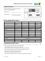
BILLY GOAT ® BC2402 Series Brush Cutter Owner’s Manual Patent Number D386768 Part No 500264 1 Form No F061207B BC2402 Series Brush Cutter Owner’s Manual ABOUT THIS MANUAL THANK YOU for purchasing a BILLY GOAT ® Brush Cutter. Your new machine has been carefully designed and manufactured to provide years of reliable and productive service. This manual provides complete operating and maintenance instructions that will help to maintain your Brush Cutter in top running order. Read this manual carefully before assembling, operating or servicing your equipment. CONTENTS Serial Plate Data ............................................................................................................................................... BC2402 Series Specifications ........................................................................................................................... Common Replacement Parts ............................................................................................................................ General Safety Instructions and Symbols ......................................................................................................... Sound Data ....................................................................................................................................................... Vibration Data .................................................................................................................................................... Intended Use ..................................................................................................................................................... Instruction Labels .............................................................................................................................................. Engine Labels .................................................................................................................................................... Assembly Instructions ....................................................................................................................................... Operation ........................................................................................................................................................... Operator Controls ....................................................................................................................................... Starting ........................................................................................................................................................ Cutting ......................................................................................................................................................... Shut Down .................................................................................................................................................. Cutting Height Adjustment .......................................................................................................................... Clearing a Clogged Cutting Deck ............................................................................................................... Handling and Transporting ................................................................................................................................ Storage .............................................................................................................................................................. Maintenance ...................................................................................................................................................... Periodic Maintenance ................................................................................................................................. Cleaning ...................................................................................................................................................... Blade Removal and Sharpening ................................................................................................................. Blade Drive Belt Tension Adjustment ......................................................................................................... Blade Clutch Adjustment ............................................................................................................................ Blade Drive Belt Removal and Replacement ............................................................................................. Transaxle Drive Clutch Adjustment ............................................................................................................ Transaxle Drive Belt Removal and Replacement ....................................................................................... Wiring Diagrams .......................................................................................................................................... Troubleshooting ................................................................................................................................................. Engine Maintenance and Repair ....................................................................................................................... Warranty Claim Procedure ................................................................................................................................ Maintenance Record ......................................................................................................................................... Illustrated Parts List ........................................................................................................................................... 3 3 3 4 6 6 6 7 7 9 10 11 11 13 14 14 14 15 15 16 16 16 17 18 19 20 22 23 21 25 26 26 27 28 Illustrations Figure 1 Figure 2 Figure 3 Figure 4 Figure 5 Figure 6 Figure 7 Figure 8 Figure 9 Brush Cutter Assembly Drawing .................................................................................................... Belt Routing Diagram ..................................................................................................................... Starter Switch Wiring ..................................................................................................................... Starter Circuit Schematic Diagram ................................................................................................ ON/OFF Switch Circuit Schematic Diagram .................................................................................. Engine and Engine Base Assembly .............................................................................................. Handlebar Assembly ...................................................................................................................... Transaxle and Blade Deck Assembly ............................................................................................ Blade Drive Spindle Assembly Detail Drawing .............................................................................. Part No 500264 2 8 21 24 24 24 28 30 32 34 F061207B BC2402 Series Brush Cutter Owner’s Manual SERIAL PLATE DATA Record the model number, serial number, date of purchase, and where purchased. Purchase Date: Purchased From: BC 2402 SERIES SPECIFICATIONS BC2402IC BC2402H BC2402HE Honda GXV BC2402ICE Engine Type Briggs and Stratton INTEK OHV Honda GXV Model Number 21A902-0149-E1 GXV390UTIDABG GXV390K1DE33 21A907-0147-E1 Horsepower 13.0 (9.7 kW) 13.0 (9.7 kW) 13.0 (9.7 kW) 13.0 (9.7 kW) Fuel Capacity 3.0 qt (2.80 L) 2.3 qt (2.18L) 2.3 qt (2.18L) 3.0 qt (2.8L) Oil Capacity 1.5 qt (1.4L) 1.2 qt (1.13L) 1.2 qt (1.13L) 1.5 qt (1.4L) Engine Weight 58.0 lb (26.3 kg) 70.5 lb (32.0 kg) 72.5 lb (32.9 kg) 60.0 lb (27.3 kg) Unit Weight 266 lb (120.7 kg) 278 lb (126.4 kg) 291 lb (132.3 kg) 273 lb (124.1 kg) In accordance with 2000/14/EEC standards 106 dB(a) 106 dB(a) 106 dB(a) 106 dB(a) Sound at Operator’s ear 93 dB(a) 93 dB(a) 93 dB(a) 93 dB(a) Shipping Weight 315 lb (143.2 kg) 330 lb (150.0 kg) 340 lb (154.7 kg) 325 lb (147.7 kg) Overall Length 82.5 in (2.09 m) Overall Width 32.0 in (0.81 m) Overall Height Maximum Operating Slope Briggs and Stratton INTEK OHV 43 in (1.09 m) 15 o 20 o 20 o 15 o COMMON REPLACEMENT PARTS - Blade. P/N 500210. Original equipment replacement blade. - High Lift Blade. P/N 500102. Optional replacement blade. - Traction Drive Belt. P/N 500119. Original equipment replacement drive belt. - Blade Drive Belt. P/N 500237. Original equipment replacement drive belt. - Skid, Right Hand. P/N 500291. Right side deck skid. - Skid, Left Hand, P/N 500292. Left side deck skid. - Throttle Control Assembly. P/N 500213. Throttle control assembly, including cable. Part No 500264 3 F061207B BC2402 Series Brush Cutter Owner’s Manual GENERAL SAFETY INSTRUCTIONS and SYMBOLS The safety symbols shown below are used throughout this manual. You should be thoroughly familiar with them before assembling, operating or servicing this equipment. This symbol indicates important information that will prevent injury to yourself or others. This symbol indicates ear protection is recommended when operating this equipment. This symbol indicates eye protection is recommended when operating this equipment. This symbol indicates gloves should be worn when servicing this equipment. This symbol indicates that this manual and the engine manufacturer’s manual should be read carefully before assembling, operation or servicing this equipment. This symbol indicates important information that will prevent damage to your BILLY GOAT Brush Cutter. ® This symbol indicates the engine oil level should be checked before operating this equipment. Read and make sure you thoroughly understand the following safety precautions before assembling, operating or servicing this equipment: READ this manual and the engine manufacturer’s manual carefully before assembling, operating or servicing this equipment. EAR PROTECTION is recommended when operating this equipment. EYE PROTECTION is recommended when operating this equipment. EXHAUST from this product contains chemicals known to the State of California to cause cancer, birth defects or other reproductive harm. DO NOT operate this equipment on any unimproved forested, brushy, or grass covered land unless a spark arrester is installed on the muffler as required by Section 4442 of the California Public Resources Code. The arrester must be maintained in good working order. Other states may have similar laws. Federal laws apply on federal lands. DO NOT run engine in an enclosed area. Exhaust gases contain carbon monoxide, an odorless and possibly fatal poison. Part No 500264 4 F061207B BC2402 Series Brush Cutter Owner’s Manual DO NOT run this equipment indoors or in any poorly ventilated area. Refueling outdoors is recommended. DO NOT refuel this equipment while the engine is running. Allow engine to cool for at least two minutes before refueling. DO NOT store gasoline near an open flame. DO NOT remove gas cap while engine is running. DO NOT start or operate engine if strong odor of gasoline is present. DO NOT start or operate engine if gasoline is spilled. Move equipment away from spill until gasoline has completely evaporated. DO NOT smoke while filling the fuel tank. DO NOT check for spark with spark plug or spark plug wire removed. Use an approved spark tester. DO NOT operate engine without a muffler. Inspect muffler periodically and replace if necessary. If equipped with muffler deflector, inspect deflector periodically and replace if necessary. DO NOT operate engine with grass, leaves or other combustible material near the muffler. DO NOT touch muffler, cylinder or cooling fins when hot. Contact with hot surfaces may cause severe burns. DO NOT leave equipment unattended while in operation. DO NOT park equipment on a steep grade or slope. DO NOT operate equipment with bystanders in or near the work area. DO NOT start equipment with drive or blade clutch engaged. DO NOT operate equipment with guards removed. DO NOT operate equipment in areas containing rock, glass, string-like material, wire, rags, cans, metal or other non-organic material. DO NOT operate equipment on slopes greater than specified in Specifications section of this manual. DO NOT operate equipment near hot or burning debris or any toxic or explosive materials. DO NOT allow children to operate this equipment. ALWAYS remove spark plug wire when servicing equipment to prevent accidental starting. ALWAYS check fuel lines and fittings frequently for cracks or leaks. Replace if necessary. ALWAYS keep hands and feet away from moving or rotating parts. ALWAYS store fuel in approved safety containers. Part No 500264 5 F061207B BC2402 Series Brush Cutter Owner’s Manual SOUND DATA SOUND LEVEL 93 Dba at Operator’s position Sound tests were conducted in accordance with 2000/14/EEC and were performed on 2/21/2002 under the conditions listed below. Sound power level listed is the highest value for any model covered in this manual. Please refer to serial plate on the unit for the sound power level for your model. General Conditions: Temperature: Wind Speed: Wind Direction: Humidity: Barometric Pressure: Sunny 80oF (25oC) 2.0 mph (3.2 kph) South 63.5% 29.98” Hg (761mm Hg) VIBRATION DATA VIBRATION LEVEL .5g (4.87 m/s2) Vibration levels at the operator’s handles were measured in the vertical, lateral and longitudinal directions using calibrated vibration test equipment. Tests were performed on 5/19/1995 under the conditions listed below. General Conditions: Temperature: Wind Speed: Wind Direction: Humidity: Barometric Pressure: Sunny 89oF (31.7oC) 6.1 mph (9.9 kph) West 49.7% 29.88” Hg (101.19 kPa) INTENDED USE Your BILLY GOAT ® BC Self-Propelled Brush Cutter is designed for cutting overgrown weeds, brush and other growth down to 3½” (8.9 cm) in height. It is not a lawn mower and does not provide the quality cut of a finish cut mower. It is designed for use in rural areas and should not be operated in tight or confined areas. Part No 500264 6 F061207B BC2402 Series Brush Cutter Owner’s Manual INSTRUCTION LABELS The labels shown below were installed on your BILLY GOAT ® Brush Cutter. If any labels are damaged or missing, replace them before operating this equipment. Item numbers from the Illustrated Parts List and part numbers are provided for convenience in ordering replacement labels. The correct position for each label may be determined by referring to the Figure and Item numbers shown. PN 400268 (See Figure 6 Item 169) PN 890254 (See Figure 6 Item 188) PN 500349 (See Figure 7 Item 186) Item No 180 - PN 400424 (See Figure 8 Item 180) Item No 184 - PN 810736 (See Figure 8 Item 184) Item No 187 - PN 890301 (See Figure 6 Item 187) PN 900327 (See Figure 6 Item 185) Item No 192 - PN 500177 (See Figure 7 Item 192) Item No 191 - PN 500176 (See Figure 7 Item 191) Item No 189 - PN 500168 (See Figure 6 Item 189) PN 500279 (See Figure 6 Item 190) ENGINE LABELS HONDA Part No 500264 BRIGGS and STRATTON 7 F061207B BC2402 Series Brush Cutter Owner’s Manual Brush Cutter Assembly Drawing Figure 1 Part No 500264 8 F061207B BC2402 Series Brush Cutter Owner’s Manual ASSEMBLY INSTRUCTIONS Your BILLY GOAT ® BC Self-Propelled Brush Cutter was shipped in one carton, completely assembled except for the upper handle assembly and the front guard bar. Mounting hardware for the handle and guard bar is temporarily installed on the lower handle and the front of the deck assembly. READ all safety instructions before assembling unit. Electric start units are shipped without a battery. A CB18, C50, SC50 or MCB50 series dry or wet battery with a 17.2 Ah rating is required. Numbers in parenthesis ( ) refer to item numbers on Figure 1 on the facing page. 1. Remove unit from carton. Make sure the following items that have been packed with unit: Upper Handle Assembly, P/N 500256 Guard Bar, P/N 500235 Owner’s Manual, P/N 500264 Honda or Briggs and Stratton Engine Manual Warranty Card, P/N 400972 Ty-Wraps (4 ea) DISCONNECT spark plug wire before assembling unit. 2. Remove mounting hardware (144, 143, 115, 117, 141) from lower handles (51 and 52). 3. Loosen (but do not remove) four screws (115) securing the lower handles (51 and 52). 4. Attach upper handle (40) to lower handles (51 and 52) with hardware removed in step 2. Tighten finger tight only. 5. Make sure engine pull starter is properly installed in guide (145) and then tighten upper handle fasteners (Honda engine only). 6. Tighten mounting hardware on handle braces (5 and 6). 7. Remove mounting hardware (102, 103, 117, 119, 124 and 141) from deck and skid assembly. 8. Attach guard bar (31) to deck. Install center bolts (152) first and then side bolts. 9. For electric start models secure the battery (not included) in the battery plate (164), hook one side of the strap into the hole then stretch the strap across the top of the battery and hook the opposite side into the opposing hole on the plate. Make sure the battery will not move then connect terminals. Items 117, 119 and 141 secure both front skid attachment and sides of front guard bar. Make sure both are securely attached. 9. Reconnect spark plug wire. Part No 500264 9 F061207B BC2402 Series Brush Cutter Owner’s Manual OPERATION DO NOT run engine in an enclosed area. Exhaust gases contain carbon monoxide, an odorless and possibly fatal poison. DO NOT start or operate engine if strong odor of gasoline is present. DO NOT start or operate engine if gasoline is spilled. Move equipment away from spill until gasoline has completely evaporated. DO NOT operate engine without a muffler. Inspect muffler periodically and replace if necessary. If equipped with muffler deflector, inspect deflector periodically and replace if necessary. DO NOT operate engine with grass, leaves or other combustible material near the muffler. DO NOT touch muffler, cylinder or cooling fins while engine is running. Contact with hot surfaces may cause severe burns. DO NOT operate equipment with bystanders in or near the work area. DO NOT operate equipment with guards removed. DO NOT operate equipment in areas containing rock, glass, string-like material, wire, rags, cans, metal or other non-organic material. DO NOT operate equipment on slopes greater than specified in Specifications section of this manual. DO NOT operate equipment near hot or burning debris or any toxic or explosive materials. DO NOT allow children to operate this equipment. ALWAYS keep hands and feet away from moving or rotating parts. ALWAYS check before use, transportation, or storage to make sure the battery is secured and straps holding battery are in good condition. If the strap breaks it will allow the battery to shift and could cause a short damaging the equipment. (Electric start) ALWAYS connect battery terminals to proper connection cables. (Electric Start) EAR PROTECTION is recommended when operating this equipment. EYE PROTECTION is recommended when operating this equipment. Part No 500264 10 F061207B BC2402 Series Brush Cutter Owner’s Manual OPERATOR CONTROLS The operator’s station is at the rear of the machine between the handlebars. The operator should STAND in a position to allow both handlebars to be grasped firmly and which allows sufficient leverage to steer the machine. Operator’s controls are shown below. 4 5 6 1 2 7 3 Operator Control Locations 1 2 3 4 Blade Clutch Lever 5 Gear Shift Lever 6 Choke 7 Throttle ON/OFF Switch Drive Clutch Lever Pull Starter STARTING CHECK engine oil level before operating machine. 1. Place equipment on a level, firm surface that is free of rocks or other debris. 2. Place throttle in START position. Throttle Part No 500264 11 F061207B BC2402 Series Brush Cutter Owner’s Manual 3. Pull choke out (Honda engine only). Choke 4. Units equipped with electric starters: Press and hold ON/OFF button until engine starts. ON/OFF (I/O) Switch I-ON O-Off (Manual start shown) DO NOT START equipment with drive or blade clutch engaged. 5. Units equipped with manual starters: Pull starter rope to start engine. Part No 500264 12 F061207B BC2402 Series Brush Cutter Owner’s Manual PULL STARTER CORD slowly until resistance is felt. Then pull cord rapidly to avoid kickback. 6. Push choke in (Honda engine only). 7. Pull throttle control back to and allow engine to reach correct operating speed. CUTTING The best performance is achieved when cutting in dry conditions. The quality of the cut is directly related to ground speed during cutting. Under most conditions cutting should be done in first or second gear. Third gear should be reserved for conditions where weeds and brush are thinned out or not very tall. If the quality of the cut is not satisfactory, shift into a lower gear. 1. Move shift lever to correct position (1, 2, 3 or Reverse) for desired gear. Gear Shift Lever 2. Press blade clutch handle down to engage blade. Allow blade to spin up to normal operating speed. Blade Clutch Lever 3. Pull drive clutch handle up to engage transaxle. Part No 500264 13 F061207B BC2402 Series Brush Cutter Owner’s Manual Drive Clutch Lever SHUT DOWN 1. Release drive clutch handle to disengage transaxle. 2. Release blade clutch handle to disengage blade. 3. Pull throttle control all the way back to the STOP position. 4. Place the ON/OFF (I/O) switch in the OFF (O) position. CUTTING HEIGHT ADJUSTMENT Cutting height can be adjusted to allow a 1” (2.54 cm) lower cutting height. This is particularly useful for cutting grasses that tend to lay over when overgrown (i.e., Bermuda, Johnson, etc). When cutting brush and normal field grasses it is recommended that you operate the brush cutter at the standard (top) cutting height. 1. Shut engine off and wait for blade to stop completely. 2. Disconnect spark plug wire. 3. Remove bolts, nuts and washers (items 119, 103, 107, 141 and 117) from skid items (155, 156). To lower the cutting height, remount the skid with the hardware in lower holes on skid bracket. To raise the cutting height use the top holes on the skid. Repeat for the opposite side. Tighten the hardware securely. 4. Reconnect the spark plug wire. CLEARING A CLOGGED CUTTING DECK DISCONNECT spark plug wire before servicing unit. 1. Shut engine off and wait for blade to stop completely. 2. Disconnect spark plug wire. 3. Remove clog from cutting deck. WEAR durable gloves. Clog may contain sharp materials. 4. Reconnect spark plug wire. Part No 500264 14 F061207B BC2402 Series Brush Cutter Owner’s Manual HANDLING and TRANSPORTING Using four people to lift unit is recommended. Lift holding the handles and front deck guard. Make sure equipment is properly secured before transporting. NEVER lift the machine while the engine is running. STORAGE DO NOT store engine in an enclosed or poorly ventilated area where fuel fumes may reach an open flame or spark from a furnace, water heater, clothes dryer or similar devices. DO NOT drain fuel in an enclosed or poorly ventilated area. DO NOT smoke when draining fuel. DO NOT remove gas cap while engine is running. DO NOT park equipment on a steep grade or slope. ALWAYS remove spark plug wire when servicing equipment to prevent accidental starting. ALWAYS keep hands and feet away from moving or rotating parts. ALWAYS store fuel in approved safety containers. If the equipment will not be used for 30 days or more, prepare as follows: 1. Make sure engine is cool. 2. Drain gasoline from carburetor and fuel tank to prevent gum deposits from forming. 3. Run engine until tank is empty and engine runs out of gas. Fuel stabilizer (such as Sta-Bil) is an acceptable alternative for minimizing the formation of gum deposits during storage. Add stabilizer to gasoline in storage container or fuel tank. Follow stabilizer manufacturer’s instructions to determine proper mix ratio. Run engine at least 10 minutes after adding stabilizer to allow it to reach carburetor. Part No 500264 15 F061207B BC2402 Series Brush Cutter Owner’s Manual MAINTENANCE PERIODIC MAINTENANCE Periodic maintenance should be performed at the following intervals: Maintenance Operation Every Use Inspect for worn or damaged parts. Daily or Every 5 Hours Every 25 Hours Every 50 Hours z Check for excessive vibration z Inspect for loose parts. z Sharpen blade. z Inspect belts for wear. z Lubricate throttle control cable and linkage. z Check blade clutch cable tension. z Inspect battery for corrosion, damage or leaks (electric start units only). z Apply anti-seize compound to rear axles. z Check battery strap for excessive wear or rips Every 100-150 Hours z z Replace blade drive and transaxle drive belts. CLEANING Your BILLY GOAT ® Brush Cutter should be cleaned periodically to ensure optimum performance and service life. Clogs and debris should be removed from the blade area and debris should be removed from the engine cooling fins. A garden hose or pressure washer may be used for cleaning. DO NOT SPRAY WATER DIRECTLY ON THE BLADE CLUTCH WHEN USING A POWER WASHER. SEE FIGURE BELOW. Part No 500264 16 F061207B BC2402 Series Brush Cutter Owner’s Manual BLADE REMOVAL AND SHARPENING READ all safety instructions before servicing unit. Numbers in parenthesis ( N-N ) refer to figure and item numbers in Illustrated Parts List. Tools required: - 5/8” socket, 1/2” drive - torque wrench, 1/2” drive - jack stands or similar device adequate to support weight of machine. DISCONNECT spark plug wire before servicing unit. 1. Disconnect spark plug wire. 2. Lift and support front of unit to allow access to underside. UNIT IS HEAVY. Make sure support is adequate to support weight of machine. 3. Block blade to prevent it from rotating during removal. 4. Remove blade bolt (8-139), lock washer (8-140) and friction washer (8-54). Blade bolt (8-139) is a standard right-hand thread bolt. 5. Remove blade (8-50) and install replacement blade. When replacing the blade use BILLY GOAT Industries PN 500210 only. When sharpening blade make sure to sharpen all cutting edges. 6. Attach new blade with bolt (8-139), lock washer (8-140) and friction washer (8-54 removed earlier. Inspect fasteners for wear and replace if necessary. 7. Torque blade bolt to 50 +/-5 ft-lbs. 8. Reconnect spark plug wire. Part No 500264 17 F061207B BC2402 Series Brush Cutter Owner’s Manual BLADE DRIVE BELT TENSION ADJUSTMENT READ all safety instructions before servicing unit. DISCONNECT spark plug wire before servicing unit. Numbers in parenthesis ( N-N ) refer to figure and item numbers in Illustrated Parts List. 1. Disconnect spark plug wire. 2. Remove two screws holding engine base door (6-7) and remove door. 3. Examine condition of belt and not position of idler assembly and amount of tension on belt. 4. Loosen, but do not remove, two nuts (6-116) on top on engine base. 5. Reset belt tension by reaching in through top of engine base with pry bar or long screwdriver and pushing idler pulley against belt to increase tension (see below). Adjusting Blade Drive Belt Tension 6. While holding belt under tension tighten two nuts (6-116) holding idler pulley in place. 7. Replace engine base door (6-7) and secure with screws removed earlier. 8. Reconnect spark plug wire. 9. Check belt tension by operating unit under conditions that caused belt slippage. If belt continues to slip it may require replacement before operation may continue. Part No 500264 18 F061207B BC2402 Series Brush Cutter Owner’s Manual BLADE CLUTCH ADJUSTMENT READ all safety instructions before servicing unit. DISCONNECT spark plug wire before servicing unit. 1. Disconnect spark plug wire. 2. As the clutch/brake wears or begins slipping or squealing, adjustment may be required to maintain proper cable tension and clutch engagement. A properly adjusted blade clutch should require 10 lbs of force to depress the end of the clutch lever. The blade clutch cable spring should stretch 1/4” to 3/8” (6.4-9.5 mm). 3. Adjust cable tension by tightening or loosening cable adjustment nut on rear of engine base (see below). Be sure to leave enough slack in cable to allow blade brake to engage. Blade Cable Adjustment If clutch continues to slip or squeal, do not operate equipment until adequate adjustment or repair has been performed. Improper adjustment can cause clutch to overheat and slip, greatly reducing performance and clutch life. 4. Reconnect spark plug wire. Part No 500264 19 F061207B BC2402 Series Brush Cutter Owner’s Manual BLADE DRIVE BELT REMOVAL AND REPLACEMENT READ all safety instructions before servicing unit. Numbers in parenthesis (N-N ) refer to figure and item numbers in Illustrated Parts List. Tools required: - 1/2” socket, 3/8” drive - ratchet, 3/8” - drive extension, 3/8” drive - universal joint, 3/8” drive - pry bar or long screwdriver - jack stands or similar device adequate to support weight of machine. DISCONNECT spark plug wire before servicing unit. 1. Disconnect spark plug wire. 2. Lift and support rear of unit to allow access to underside. UNIT IS HEAVY. Make sure support is adequate to support weight of machine. 3. Remove two screws (6-103) and washers (6-141) holding engine base door (6-7) and remove door. 4. Loosen, but do not remove, two nuts (6-116) holding idler mounting plate (6-26) to relieve tension on blade drive belt (8-29). It may be necessary to pry idler pulley (8-9) away from its original position to release belt. 5. Using drive extension and universal joint, loosen, but do not remove, four screws (6-107) holding belt guides (6-149, 6-150) in place next to crankshaft drive pulley (8-9) at rear of machine. If extension and universal joint are not available, remove stop bolt (6-110) and nuts (6-116, 6117) to allow idler arm to swing back and allow access to screws (6-107). 6. Pull transaxle drive belt (8-10) from groove on pulley (8-9). 7. Pull blade drive belt (8-29) from groove on pulley (8-9) and down past pulley. 8. Pull belt back through hole in top of engine base and remove it from machine. It will take some force to walk the belt past the front portion of the pulley. 9. Install new blade drive belt (8-29) on groove in pulley (8-9). Push remaining length of belt back through engine base toward clutch/brake drive pulley. 10. Install transaxle drive belt (8-10) on groove in pulley (8-9). 11. Reach through from rear of machine and pull new belt through and install it in the groove on the clutch/brake drive pulley. Part No 500264 20 F061207B BC2402 Series Brush Cutter Owner’s Manual Make sure blade drive belt is properly seated in clutch/brake drive pulley (6-23) and is not resting in gap between clutch/brake drive pulley (6-23) and transaxle drive pulley (6-46) 12. Tighten four screws (6-103) to secure belt guides (6-149, 6-150). Make sure belt is correctly routed. (See Figure 2). 13. Adjust blade drive belt tension by reaching in through top of engine base with pry bar or long screwdriver and pushing idler pulley against belt to increase tension (see below). Adjusting Blade Drive Belt Tension 14. While holding belt under tension tighten two nuts (6-116) securing idler plate. 15. Check belt tension by applying force on side of belt opposite idler pulley. Belt should deflect 3/16”-1/4” (4.86.4 mm) with force applied perpendicular to belt. 16. Replace engine base door (6-7) and secure with screws (6-103) and washers (6-141). 17. Reconnect spark plug wire. FRONT LOOKING THROUGH TOP Blade Drive Belt (with Transaxle Belt not Shown) Blade Drive Belt (Between Transaxle Drive Belt and Deck) Transaxle Drive Belt Belt Routing Diagram (Top View of Machine) Figure 2 Part No 500264 21 F061207B BC2402 Series Brush Cutter Owner’s Manual TRANSAXLE DRIVE CLUTCH ADJUSTMENT READ all safety instructions before servicing unit. DISCONNECT spark plug wire before servicing unit. 1. Disconnect spark plug wire. 2. As the belt wears or begins slipping or squealing, adjustment may be required to maintain proper cable tension and clutch engagement. A properly adjusted transaxle drive clutch should require 3 lbs of force to depress the end of the clutch lever. 3. Adjust cable tension by tightening or loosening cable adjustment barrel on rear of engine base (see below). Moving the cable adjustment barrel IN decreases clutch tension. Moving the barrel OUT increases tension. DECREASE INCREASE Transaxle Cable Adjustment 4. Reconnect spark plug wire. Part No 500264 22 F061207B BC2402 Series Brush Cutter Owner’s Manual TRANSAXLE DRIVE BELT REMOVAL AND REPLACEMENT READ all safety instructions before servicing unit. Numbers in parenthesis ( N-N ) refer to figure and item numbers in Illustrated Parts List. Tools required: ½” socket and ratchet, ½” universal extension bar, pry bar or long screwdriver, adequate support for machine. - 1/2” socket, 3/8” drive - ratchet, 3/8” - drive extension, 3/8” drive - universal joint, 3/8” drive - pry bar or long screwdriver - jack stands or similar device adequate to support weight of machine. DISCONNECT spark plug wire before servicing unit. 1. Disconnect spark plug wire. 2. Lift and support rear of unit to allow access to underside. UNIT IS HEAVY. Make sure support is adequate to support weight of machine. 3. Using drive extension and universal joint, loosen, but do not remove, four screws (6-107) holding belt guides (6-149, 6-150) in place next to crankshaft drive pulley (8-9) at rear of machine. If extension and universal joint are not available, remove stop bolt (6-10) and nuts (6-116, 6117) to allow idler arm to swing back and allow access to screws (6-107). 4. Pull belt (8-10) from groove on pulley (8-9) and down past pulley. 5. Slip belt (8-10) up and over pulley (8-9) and remove belt from machine. 6. Install new belt in grooves on pulley (6-46) and transaxle drive pulley (8-9). 7. Tighten four screws (6-107) to secure belt guides (6-149, 6-150). 8. Engage clutch levers and make sure belt guides do not touch belts. 9. Reconnect spark plug wire. Part No 500264 23 F061207B BC2402 Series Brush Cutter Owner’s Manual WIRING DIAGRAMS Starter Switch Wiring Figure 3 RED FUSE B RED RED 20A SWITCH STARTER SOLENOID A1 WHITE + BATTERY STARTER MOTOR - M BLACK BLACK ENGINE GROUND Starter Circuit Schematic Diagram Figure 4 MAGNETO ON/OFF SWITCH SPARK PLUG ENGINE GROUND ON/OFF Switch Circuit Schematic Diagram Figure 5 Part No 500264 24 F061207B BC2402 Series Brush Cutter Owner’s Manual TROUBLESHOOTING Problem Possible Cause Corrective Action Engine will not start. ON/OFF switch is in OFF position. Move switch to START position. Out of gasoline. Fill gas tank. Old or contaminated gasoline. Drain gas tank and fill with fresh gasoline. Spark plug wire disconnected. Connect spark plug wire. Dirty air cleaner. Clean or replace air cleaner. Starter does not turn. Battery low or dead. Charge or replace battery. (Electric start only) Battery cable disconnected or corroded. Clean and secure battery terminals. Defective starter switch or wiring harness. Replace starter switch or wiring harness. Defective starter. Replace starter. Blade drive belt tension incorrect. Adjust blade drive belt tension. Dull blade. Sharpen or replace blade. Clogged deck. Unclog deck. Excessive debris built up on or blocking blade. Clear debris from blade area. Engine RPM set too low. Check engine RPM. Blade loose or out of balance. Check blade for tightness. Rebalance if necessary. Engine loose. Check engine mounting bolts. Blade drive belt worn. Replace blade drive belt. Belt tension too low. Adjust belt tension. Belt worn or stretched. Replace belt. Pulleys worn or damaged. Replace pulleys. Clutch cable tension too low. Adjust clutch tension. Clutch worn or damaged. Replace worn or defective clutch assembly parts. Inadequate slack in clutch cable. Adjust clutch cable. Clutch worn or damaged. Replace clutch/brake assembly. Clutch lever not engaging clutch. Adjust clutch cable. Clutch cable defective. Replace cable. Belt worn or broken. Replace belt. Transaxle will not disengage. Clutch cable out of adjustment. Adjust clutch cable. Engine will not turn over. Defective blade clutch. Replace clutch. Engine problem. Contact an authorized servicing dealer for your engine. Will not cut or cutting performance is poor. Abnormal vibrations. Belt slips or smokes. Clutch slips or squeals. Blade brake will not engage. Transaxle will not engage. Part No 500264 25 F061207B BC2402 Series Brush Cutter Owner’s Manual ENGINE MAINTENANCE AND REPAIR Refer to the engine manufacturer’s manual for maintenance and service information. Warranty coverage on the engine is the responsibility of the engine manufacturer. If your engine requires warranty repair contact your local servicing engine dealer. Have your engine model number and serial number ready when you contact the dealer. If you cannot locate a servicing dealer in your area, you may contact the manufacturer’s national service organization at the following numbers: American Honda Briggs and Stratton (800) 426-7701 (800) 233-3723 WARRANTY CLAIM PROCEDURE Should a BILLY GOAT ® machine fail due to a defect in material and/or workmanship, the owner should make a warranty claim as follows: - The machine must be taken to the dealer from whom it was purchased or to an authorized Servicing BILLYGOAT Dealer. - The owner must present the remaining half of the Warranty Registration Card, or, if this is not available, the invoice or receipt. - The Warranty Claim will be completed by the authorized BILLY GOAT Dealer and submitted to their respective BILLY GOAT Distributor for their territory Attention: Service Manager. Any parts replaced under warranty must be tagged and retained for 90 days. The model number and serial number of the unit must be stated in the Warranty Claim. - The distributor service manager will sign off on the claim and submit it to BILLY GOAT for consideration. - The Technical Service Department at BILLY GOAT will study the claim and may request parts to be returned for examination. BILLY GOAT will notify their conclusions to the distributor service manager from whom the claim was received. - The decision by the Service Department at BILLY GOAT to approve or reject a Warranty Claim is final and binding. Part No 500264 26 F061207B BC2402 Series Brush Cutter Owner’s Manual MAINTENANCE RECORD Date Part No 500264 Service Performed 27 F061207B BC2402 Series Brush Cutter Owner’s Manual ILLUSTRATED PARTS LIST Engine and Engine Base Assembly Figure 6 Part No 500264 28 F061207B BC2402 Series Brush Cutter Owner’s Manual ITEM NO DESCRIPTION BC2402HE BC2402H BC2402ICE BC2402IC Part No QTY Part No QTY Part No QTY Part No QTY 4 Base Assembly with labels 500240 1 500240 1 500240 1 500240 1 7 Door Base Engine 500233 1 500233 1 500233 1 500233 1 22 Tube Shift With Grip 500171 1 500171 1 500171 1 500171 1 23 Clutch Brake 500338 1 500338 1 500338 1 500338 1 24 Grip 3/4 ID - Black 610102 1 610102 1 610102 1 610102 1 26 Plate Mount Idler WA 500228 1 500228 1 500228 1 500228 1 27 Pulley Idler 4.5" OD X 3/8” 500270 1 500270 1 500270 1 500270 1 32 Bushing Shifter 500130 1 500130 1 500130 1 500130 1 45 13 HP Honda GXV390 Electric Start 500333 1 - - - - - - 45 13 HP Honda GXV390 - - 500334 1 - - - - 45 13 HP OHV B & S - - - - - - 520046 1 45 13 HP OHV Briggs Electric Start - - - - 520039 1 - - 46 Pulley Drive Traction BC 500238 1 500238 1 500238 1 500238 1 1 47 Spacer Engine WA 2401 500262 1 500262 1 500262 1 500262 100 Roll Pin 1/4 x 1 1/4 500351 1 500351 1 500351 1 500351 1 103 Screw Cap 5/16-18 x 1-1/4” *8041029 2 *8041029 2 *8041029 2 *8041029 2 104 Washer Split Lock 5/16” *8177011 2 *8177011 2 *8177011 2 *8177011 2 105 Plate Impeller Washer 850443 1 850443 1 850443 1 850443 1 106 Screw Cap 7/16-20 X 3" 500269 1 500269 1 500269 1 500269 1 109 Bolt Carriage 5/16-18 x 3/4 “ 8024039 4 8024039 6 8024039 4 8024039 6 110 Washer Flat 1/2" 900230 2 900230 2 900230 2 900230 2 113 Nut Lock 3/8-16 *8160003 2 *8160003 2 *8160003 2 *8160003 2 116 Nut Jam 5/16-18 *8142002 2 *8142002 2 *8142002 2 *8142002 2 117 Nut Lock 5/16-18 *8160002 8 *8160002 8 *8160002 10 *8160002 10 118 Bolt Carriage 5/16-18 x 1” *8024040 4 *8024040 2 *8024040 4 *8024040 2 120 Washer 3/8 FC *8171004 1 *8171004 1 *8171004 1 *8171004 1 121 Terminal Piggyback 3/16 890010 1 890010 1 - - - - 131 Spacer Engine 830113 1 830113 1 830113 1 830113 1 140 Washer Lock 7/16” 850132 1 850132 1 850132 1 850132 1 141 Washer 5/16” FC *8171003 6 *8171003 6 *8171003 8 *8171003 8 143 Screw Cap 5/16-18 x 1-3/4” *8041031 1 *8041031 2 *8041031 1 *8041031 4 149 Guide Belt LH 500230 1 500230 1 500230 1 500230 1 150 Guide Belt RH 500231 1 500231 1 500231 1 500231 1 151 Screw Cap 5/16-24 x 1” *400164 2 *400164 2 162 Cable Battery Red W/Charge 500304 1 - - 520111 - - - 163 Cable Battery Black 10" 790133 1 - 790133 1 - - 164 Bracket Battery Rear 500347 1 - 500347 1 - - 165 Strap Hold Down 790303 1 - - 790303 1 - - 166 Washer 1/4” SAE 8172007 2 8172007 2 8172007 2 8172007 2 167 Screw Cap 1/4-20 x 3/4” 8041004 2 8041004 2 8041004 2 8041004 2 168 Cable Battery Positive 8" - - - - 520123 1 - - 169 Label Hot Engine 400268 1 400268 1 400268 1 400268 1 185 Label Guards 900327 2 900327 2 900327 2 900327 2 - 186 187 Label Read 890301 1 890301 1 890301 1 890301 1 188 Label Ear Eye Breathe 890254 1 890254 1 890254 1 890254 1 189 Label Chock Wheels 500168 1 500168 1 500168 1 500168 1 190 Label Patent No 500279 1 500279 1 500279 1 500279 1 193 Plate Choke Mount BC 500325 1 500325 1 - - - - 194 Screw Machine 10-32 x 3/4" 430248 1 430248 1 - - - - 195 Control Cable Choke BC 500326 1 500326 1 - - - - 196 Ring Retaining External 3/4” 520176 1 520176 1 520176 1 520176 1 198 Label Outback BC 500293 2 500293 2 500293 2 500293 2 199 Label Product Decal 890456 1 890456 1 890456 1 890456 1 200 Screwcap 5/16 –18 x 2 8041032 1 8041032 1 Part No 500264 29 F061207B BC2402 Series Brush Cutter Owner’s Manual Handlebar Assembly Figure 7 Part No 500264 30 F061207B BC2402 Series Brush Cutter Owner’s Manual ITEM NO BC2402HE DESCRIPTION BC2402H BC2402ICE BC2402IC Part No QTY Part No QTY Part No QTY Part No QT Y 5 Handle Brace Left 500196 1 500196 1 500196 1 500196 1 6 Handle Brace Right 500200 1 500200 1 500200 1 500200 1 17 Cable Clutch Blade BC2402 500259 1 500259 1 500259 1 500259 1 18 Cable Clutch Drive BC2402 500327 1 500327 1 500327 1 500327 1 39 Lever Control Blade 500312 1 500312 1 500312 1 500312 1 40 Handle Upper BC2402 500243-S 1 500243-S 1 500243-S 1 500243-S 1 41 Grip Handle 1” ID x 7.5” 500267 2 500267 2 500267 2 500267 2 42 Lever Control Clutch 500142 1 500142 1 500142 1 500142 1 43 Bushing Lever Control 500152 4 500152 4 500152 4 500152 4 44 Fitting Mount Cable 500187 2 500187 2 500187 2 500187 2 48 Throttle Control, Including Cable 500213 1 500213 1 500213 1 500213 1 51 Handle Lower RH BC2402 500140 1 500140 1 500140 1 500140 1 52 Handle Lower LH BC2402 500141 1 500141 1 500141 1 500141 1 55 Guard Hand BC2402 500339 2 500339 2 500339 2 500339 2 56 Screw Cap 8-3/8 HWH Type B 100121 2 100121 2 100121 2 100121 2 102 Nut Lock 1/4-20 *8160001 7 *8160001 7 *8160001 6 *8160001 6 108 Screw Cap 5/16-18 x 2-3/4” *8041035 1 *8041035 1 *8041035 1 *8041035 1 115 Screw Cap 5/16-18 x 2" *8041032 4 *8041032 2 *8041032 4 *8041032 2 117 Nut Lock 5/16-18 *8160002 10 *8160002 10 *8160002 10 *8160002 10 119 Screw Cap 5/16-18 x 1-1/2” *8041030 4 *8041030 4 *8041030 4 *8041030 4 124 Washer 1/4” FC *8171002 2 *8171002 2 *8171002 2 *8171002 2 137 Ty Wrap 900407 4 900407 4 900407 4 900407 4 141 Washer 5/16” FC *8171003 5 *8171003 5 *8171003 7 *8171003 7 142 Bracket Clutch Cable Guard 500321 1 500321 1 500321 1 500321 1 143 Screw Cap 5/16-18 x 1-3/4” *8041031 4 *8041031 5 *8041031 6 *8041031 7 144 Screw Cap 5/16-18 x 2-1/2” *8041034 1 *8041034 1 *8041034 1 *8041034 1 145 Guide Rope (Honda only) 830533 2 830533 2 146 Grip Lever 500181 2 500181 2 500181 2 500181 2 147 Label Start/Stop Toggle 500329 1 500329 1 153 Screw Cap 1/4-20 x 3” *8041014 1 *8041014 1 *8041014 1 *8041014 1 154 *8041010 2 *8041010 2 *8041010 2 *8041010 2 500318 1 500283-S 1 500318 1 500283-S 1 158 Screw Cap 1/4-20 x 2” Switch Box Assy BC (includes throttle cable) Switch Toggle, ON/OFF 500307 1 500281 1 500307 1 500281 1 159 Harness Assy 500306 1 890442 1 520118 1 890442 1 160 Bushing Strain Relief 500282 1 500282 1 500282 1 500282 1 161 Label Throttle 810656 1 810656 1 810656 1 810656 1 170 Bolt Shoulder 5/16-18 x 1-1/2” 500340 2 500340 2 500340 2 500340 2 157 186 Label Shift BC2402 500349 1 500349 1 500349 1 500349 1 191 Label Clutch Drive 500176 1 500176 1 500176 1 500176 1 192 Label Clutch Blade 500177 1 500177 1 500177 1 500177 1 Part No 500264 31 F061207B BC2402 Series Brush Cutter Owner’s Manual Transaxle and Blade Deck Assembly Figure 8 Part No 500264 32 F061207B BC2402 Series Brush Cutter Owner’s Manual ITEM NO 1 3 8 9 10 11 12 13 14 15 16 19 20 21 28 29 30 31 33 34 35 36 37 38 49 50 53 54 101 102 103 104 107 108 109 111 112 113 114 116 117 119 122 123 124 125 126 128 129 130 132 133 135 136 138 139 140 141 152 155 156 180 184 197 200 201 DESCRIPTION BC2402HE BC2402H BC2402ICE BC2402IC Part No QTY Part No QTY Part No QTY Part No QTY Deck Assembly with Labels Deflector Front BC2402 Transaxle 3 SPD BC2402 Pulley 5.0" OD ‘A’ Section Belt Traction Drive Plate Pivot Idler/Shifter Shifter Pivot WA Pulley Idler Wheel & Tire 16" SP LH Wheel & Tire 16" SP RH Arm Idler WA Bar Shift T-axle Angle Support T-axle Rod Link Shifter 500239 500125 500342 830180 500119 500122 500169 800260 500343 500344 500170 500121 500127 500144 1 1 1 1 1 1 1 1 1 1 1 1 1 1 500239 500125 500342 830180 500119 500122 500169 800260 500343 500344 500170 500121 500127 500144 1 1 1 1 1 1 1 1 1 1 1 1 1 1 500239 500125 500342 830180 500119 500122 500169 800260 500343 500344 500170 500121 500127 500144 1 1 1 1 1 1 1 1 1 1 1 1 1 1 500239 500125 500342 830180 500119 500122 500169 800260 500343 500344 500170 500121 500127 500144 1 1 1 1 1 1 1 1 1 1 1 1 1 1 Belt Blade Drive Spacer Spindle BC2402 Bar Guard WA BC2402 500237 500232 500235 1 1 1 500237 500232 500235 1 1 1 500237 500232 500235 1 1 1 500237 500232 500235 1 1 1 500174 500101 500107 500115 500253 8161042 500210 500191 500108 8024021 *8160001 *8041029 *8177011 *8041028 *8041035 8024039 *8197016 500114 *8160003 800888 *8142002 *8160002 *8041030 850408 8181008 *8171002 *8123128 900471 8197016 *8172015 850238 850230 9201087 800554 350153 9201072 500188 850132 *8171003 *8041007 500291 500292 400424 810736 800177 430298 850233 1 2 1 1 1 1 1 1 1 4 6 11 5 8 4 4 1 1 1 1 1 7 2 1 1 3 1 2 1 2 2 2 2 1 1 2 1 2 10 2 1 1 2 1 2 4 1 500174 500101 500107 500115 500253 8161042 500210 500191 500108 8024021 *8160001 *8041029 *8177011 *8041028 *8041035 8024039 *8197016 500114 *816003 800888 *8142002 *8160002 *8041030 850408 8181008 *8171002 *8123128 900471 8197016 *8172015 850238 850230 9201087 800554 350153 9201072 500188 850132 *8171003 *8041007 500291 500292 400424 810736 800177 430298 850233 1 2 1 1 1 1 1 1 1 4 6 11 5 8 4 4 1 1 1 1 1 7 2 1 1 3 1 2 1 2 2 2 2 1 1 2 1 2 10 2 1 1 2 1 2 4 1 500174 500101 500107 500115 500253 8161042 500210 500191 500108 8024021 *8160001 *8041029 *8177011 *8041028 *8041035 8024039 *8197016 500114 *8160003 800888 *8142002 *8160002 *8041030 850408 8181008 *8171002 *8123128 900471 8197016 *8172015 850238 850230 9201087 800554 350153 9201072 500188 850132 *8171003 *8041007 500291 500292 400424 810736 800177 430298 850233 1 2 1 1 1 1 1 1 1 4 6 11 5 8 4 4 1 1 1 1 1 7 2 1 1 3 1 2 1 2 2 2 2 1 1 2 1 2 10 2 1 1 2 1 2 4 1 500174 500101 500107 500115 500253 8161042 500210 500191 500108 8024021 *8160001 *8041029 *8177011 *8041028 *8041035 8024039 *8197016 500114 *8160003 800888 *8142002 *8160002 *8041030 850408 8181008 *8171002 *8123128 900471 8197016 *8172015 850238 850230 9201087 800554 350153 9201072 500188 850132 *8171003 *8041007 500291 500292 400424 810736 800177 430298 850233 1 2 1 1 1 1 1 1 1 4 6 11 5 8 4 4 1 1 1 1 1 7 2 1 1 3 1 2 1 2 2 2 2 1 1 2 1 2 10 2 1 1 2 1 2 4 1 Spindle WA BC2402 Bearing 7/8" ID Sealed Press Shaft Drive Blade Spacer Spindle Bearing Pulley 7" OD x 7/8" Bore Nut Lock 3/8-16 Thin Blade 24" BC2402 Adapter Blade WA Washer Friction Blade Bolt Carriage 1/4-20 x 3/4” Nut Lock 1/4-20 Screw Cap 5/16-18 x 1-1/4” Washer Split Lock 5/16” Screw Cap 5/16-18 x 1" Screw Cap 5/16-18 x 2-3/4 “ Bolt Carriage 5/16-18 x 3/4 “ Pin Cotter 3/32 x 3/4" Bolt Shoulder 1/2 x 1” Nut Lock 3/8-16 Bolt Idler Nut Jam 5/16-18 Nut Lock 5/16-18 Screw Cap 5/16-18 x 1-1/2” Screw Cap 1/4-28 x 1/2” GR5 Washer Lock 5/16” External Tooth Washer 1/4” FC Screw Self Tap 5/16” Pin Hair Cotter Pin Cotter 3/32 x 3/4” Washer 3/4” SAE Washer 0.765 x 1.250 x 0.060” Ring Snap 0.750” Key 3/16 x 2-1/8” Screw Cap 7/16-20 x 1-1/4” GR8 Washer 7/8 SAE Key Sq 3/16 x 5/8” Screw Cap 7/16-20 x 2” GR8 Washer Lock 7/16” Washer 5/16 FC Screw Cap 1/4-20 x 1-1/4” Skid RH Skid LH Label OPEI Label Flying Debris Washer Lock 5/16 twisted tooth Washer Lock 5/16 twisted tooth heavy Snap ring Part No 500264 33 F061207B BC2402 Series Brush Cutter Owner’s Manual Blade Drive Spindle Assembly Detail Drawing Figure 9 Part No 500264 34 F061207B BC2402 Series Brush Cutter Owner’s Manual ITEM NO DESCRIPTION BC2402HE Part No QTY BC2402H Part No QTY BC2402ICE Part No QTY BC2402IC Part No QTY 134 Spindle Assembly Complete 500242 1 500242 1 500242 1 500242 1 30 Spacer Spindle BC2402 500232 1 500232 1 500232 1 500232 1 34 Spindle WA BC2402 500174 1 500174 1 500174 1 500174 1 35 Bearing 7/8" ID Sealed Press 500101 2 500101 2 500101 2 500101 2 36 Shaft Drive Blade 500107 1 500107 1 500107 1 500107 1 37 Spacer Spindle Bearing 500115 1 500115 1 500115 1 500115 1 38 Pulley 7" OD x 7/8" Bore 500253 1 500253 1 500253 1 500253 1 53 Adapter Blade WA 500191 1 500191 1 500191 1 500191 1 54 Washer Friction Blade 500108 1 500108 1 500108 1 500108 1 135 Screw Cap 7/16-20 x 1-1/4” GR8 800554 1 800554 1 800554 1 800554 1 136 Washer 7/8 SAE 350153 1 350153 1 350153 1 350153 1 138 Key Sq 3/16 x 5/8” 9201072 2 9201072 2 9201072 2 9201072 2 139 Screw Cap 7/16-20 x 2” GR8 500188 1 500188 1 500188 1 500188 1 140 Washer Lock 7/16” 850132 2 850132 2 850132 2 850132 2 Part No 500264 35 F061207B BC2402 Series Brush Cutter Owner’s Manual HIGH WHEEL MOWER FORCE BLOWER AERATOR If you liked this product please feel free to view our full line of quality lawn care, renovation, and debris removal products at www.billygoat.com QL VACUUM Part No 500264 MULTI VACUUM 36 POWER RAKE F061207B