1
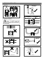
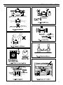
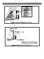
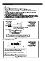
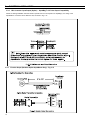
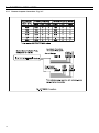
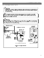
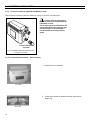
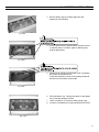
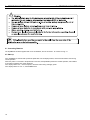
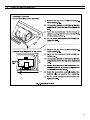
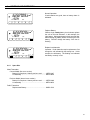
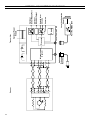
AquaMaster™
Installation Manual
Use of Instructions
Warning.
An instruction that draws attention to the risk of
injury or death.
Note.
Clarification of an instruction or additional
information.
Caution.
An instruction that draws attention to the risk of
damage to the product, process or surroundings.
Information.
Further reference for more detailed information
or technical details.
Although Warning hazards are related to personal injury, and Caution hazards are associated with equipment or
property damage, it must be understood that operation of damaged equipment could, under certain operational conditions, result in degraded process system performance leading to personal injury or death. Therefore, comply fully
with all Warning and Caution notices.
Information in this manual is intended only to assist our customers in the efficient operation of our equipment. Use
of this manual for any other purpose is specifically prohibited and its contents are not to be reproduced in full or part
without prior approval of the Marketing Communications Department.
Health and Safety
To ensure that our products are safe and without risk to health, the following points must be noted:
1. The relevant sections of these instructions must be read carefully before proceeding.
2. Warning labels on containers and packages must be observed.
3. Installation, operation, maintenance and servicing must only be carried out by suitably trained personnel
and in accordance with the information given.
4. Normal safety precautions must be taken to avoid the possibility of an accident occurring when operating
in conditions of high pressure and/or temperature.
5. Chemicals must be stored away from heat, protected from temperature extremes and powders kept dry.
Normal safe handling procedures must be used.
6. When disposing of chemicals ensure that no two chemicals are mixed.
Safety advice concerning the use of the equipment described in this manual or any relevant hazard data
sheets (where applicable) may be obtained from the Company address on the back cover, together with
servicing and parts information.
© 2002 ABB Water Meters. All rights reserved.
CONTENTS
1 INTRODUCTION
1
INTRODUCTION ....................................1
2
MECHANICAL INSTALLATION ............ 2
2.1 Unpacking ....................................... 2
2.2 Installation Conditions ..................... 2
2.3 Mechancial Installation .................... 4
AquaMaster™ includes the family of high performance
electromagnetic flow meters for water measurement that
normally are supplied as factory configured, calibrated systems.
2.3.1
3
Transmitters ............................ 4
ELECTRICAL INSTALLATION ............. 5
3.1 Grounding ....................................... 5
3.2 Connections .................................... 6
3.2.1
3.2.2
3.2.3
Sensor Terminal Box
Connections
(Remote Versions only) .......... 6
Environmental Protection ....... 6
Transmitter Connections ......... 7
3.3 Input/Output Connections ............... 10
3.3.1
3.3.2
3.3.3
Frequency Outputs .................
Alarm Interface .......................
MIL Connector Input/Output
Connections (Option) ..............
MIL Connector Input/Output
(Option) - AquaMag™ x10
Pulse Output Compatibility .....
Encoder Output
(Option) ...................................
Local Computer
Connection .............................
Remote Computer
Connection .............................
Power Supply Connection ......
Pressure Transducer
(Optional) ................................
Environmental Protection .......
10
10
START-UP AND OPERATION .............
4.1 Connecting Batteries ......................
4.2 Start-up ...........................................
4.3 Display Activation ...........................
4.4 Replacing a Battery ........................
17
17
17
19
19
3.3.4
3.3.5
3.3.6
3.3.7
3.3.8
3.3.9
3.3.10
4
4.4.1
4.4.2
11
Warning.
! Installation and maintenance must only be
carried out by suitably trained personnel.
! All relevant sections of this manual must
be read before selecting a location.
! Safety requirements of this equipment,
any associated equipment and the local
environment must be taken into
consideration.
! The installation and use of this equipment
must be in accordance with relevant
national and local standards.
12
12
13
14
15
16
16
Spares Kits ............................. 20
Battery Changing
Procedures ............................. 21
APPENDIX - AQUAMASTER BLOCK
DIAGRAM ............................................. 23
1
2 MECHANICAL INSTALLATION
2.1 Unpacking
Allow room to
read display
AquaMaster
AquaMaster
AquaMaster
AquaMaster
Fig. 2.5 Siting
Fig. 2.1 Unpacking
2.2 Installation Conditions
>2 x pipe dia.
>5 x pipe dia.
minimum
minimum
Caution. Do NOT exceed the
maximum working pressure marked on
the equipment.
Flow Direction
Fig. 2.6 Straight Pipe Requirements
Fig. 2.7 Fluid Level
Fig. 2.2 Spillage
140°F (60°C)
Maximum
AquaMaster
-4°F (-20°C)
Minimum
2
Fig. 2.3 Vibration
Fig. 2.8 Within Temperature Limits
Fig. 2.4 Localized Heat
Fig. 2.9 Shade
2
MECHANICAL INSTALLATION...
3
...2
MECHANICAL INSTALLATION
2.3 Mechanical Installation
2.3.1
Transmitter
Installation and wiring
access 12" minimum,
18" preferred
AquaMaster Transmitter
5.7"
(146mm)
4.9"
(125mm)
6.7"
(170mm)
5.9"
(150mm)
7
(176mm)
0.25"
(6.5mm)
0.50"
(13mm)
AquaMaster
6.1
(155mm)
5.5
(140mm)
0.25"
(6.5mm)
Transmitter Mounting Plate
Allowance for cable bend - each side
6" (Standard)
9" (Armored)
Fig. 2.18 Transmitter Dimensions
4
3 ELECTRICAL INSTALLATION
3.1
3 ELECTRICAL INSTALLATION...
Grounding (Figs. 3.1 to 3.2)
Supplied Bonding Cable
Bond this end of the
meter to the pipeline Insulating Sleeve
Insulated connecting
(using grounding
and Washer
wire (not included).
ring if required)
(not provided)
Must be adequately
rated to carry
cathodic currents.
Supplied Bonding
Cables
Gasket Gasket
Grounding Ring
Note. 5/8" to 1" threaded end
sensors will require a plastic isolation
section in the pipe, and a cathodic
current bypass wire.
Caution. Do NOT ground
Cathodically Protected Systems.
Fig. 3.2 Pipelines with Cathodic Protection
5
...3
ELECTRICAL INSTALLATION
3.2 Connections
3.2.1 Sensor Terminal Box Connections (Remote Versions Only)
(Remote Versions Only)
Fig. 3.6 Potting the Terminal Box
6
Warning.
! Potting materials are toxic — use suitable
safety precautions.
! Read the manufacturer’s instructions carefully
before preparing the potting material.
! The remote sensor terminal box connections
must be potted immediately on completion to
prevent the ingress of moisture.
! Check all connections before potting see
ELECTRICAL INSTALLATION.
! Do not overfill or allow the potting material to
come into contact with “O” rings or grooves.
! Do not let potting material enter conduit, if
used.
3
3.2.3
ELECTRICAL INSTALLATION...
Transmitter Connections
7
...3
8
ELECTRICAL INSTALLATION
3
ELECTRICAL INSTALLATION...
9
...3
ELECTRICAL INSTALLATION
3.3 Input/Output Connections
3.3.1
3.3.2
10
Frequency Outputs - Fig. 3.11
Alarm Interface - Fig. 3.12
3
3.3.3
ELECTRICAL INSTALLATION...
MIL connector Input/Output connections (Option) - Fig. 3.13
11
3
ELECTRICAL INSTALLATION...
3.3.6
MIL Connector Input/Output (Option) - AquaMag™ x10 Pulse Ouput Compatibility
Where an existing installation has been wired to operate from the x10 outputs of an AquaMag™, the wiring of the
AquaMaster™ connector can be altered to suit, as shown in Fig. 3.14.
3.3.5
12
Encoder Ouput (Standard Option AquaMaster Only) - Fig. 3.15
3
3.3.6
ELECTRICAL INSTALLATION...
Local Computer Connection - Fig. 3.16
Connected to 9-pin
Serial Data socket on
PDA or PC via
'Laplink' lead/adaptor
AquaMaster Transmitter
Original Style
°
ABB Part No.WEBC2000
Current Style
9-pin female
(direct to PC)
Fig. 3.16 Local Computer Connections
13
3
3.3.7
14
ELECTRICAL INSTALLATION...
Remote Computer Connection - Fig. 3.17
3
3.3.8
ELECTRICAL INSTALLATION...
Power Supply connection - Fig. 3.18
AC or AC/Battery Powered Units
Battery Powered Units
15
3
ELECTRICAL INSTALLATION...
3.3.9
Pressure Transducer (Optional AquaMaster S only)
Optional pressure transducer cables are available for a range of pressures and cable lengths.
Caution. Ensure that only the
pressure transducer supplied with the
transmitter is used.
Use of other pressure transducers will
require alteration of the pressure span
and zero factors in the transmitter —
see Quick Reference Programming
guide.
Pressure Transducer
Connector
Fig. 3.19 AquaMaster fitted with OptionalPressure
Transducer Connector
3.3.10 Environmental Protection - Sensor Potting
1. Remove lid from transmitter.
Fig. 3.20a
2. If fitted, note position of batteries and then remove from
battery tray.
Fig. 3.20b
16
3
ELECTRICAL INSTALLATION...
3. Remove battery tray by pushing right-most clips
towards the left and lifting
Fig. 3.20c
4. Check to insure that all required cables are fitted correctly and that either a connector, gland or blanking plug
seals all gland holes.
Fig. 3.20d
5. Carefully pour potting into termination area, until potting
just covers the terminal blocks.
To prevent possibility of short circuit, potting compound
should cover all terminal screw heads.
Fig. 3.20e
6. Re-insert battery tray. Gently press down on the battery
tray so that the potting level rises.
7. Leave to stand for 15 minutes to allow potting to gel.
8. If present, refit batteries to original positions and refit lid.
Fig. 3.20f
17
4 START-UP AND OPERATION
4 START-UP AND OPERATION...
4.1 Connecting Batteries
The AquaMaster has been supplied with one or two batteries, but not connected. To connect see Fig. 4.1
4.2 Start-up
If the AquaMaster is received with a protective plastic film over the display window, remove this film before commencing
normal operation.
When the power is connected or the plastic film is removed, the AquaMaster performs a self test operation, and indicates
a successful completion with “Pass” displayed.
If the display shows “Err1”, remove all power, check the sensor wiring and apply power.
If the display shows “Err 2 or 3”, contact ABB Service.
18
...4
START-UP AND OPERATION
19
4
Pictorial Displays
Warning annunciators
Left Battery Warning
Sensor Fault
88888.888.8
AB CD 0
.8.8.8.80
m3
gal
ftm 3 /hMGD
gal/sm Barpsi
START-UP AND OPERATION...
Upper Display
Date
Forward Flow Total
Reverse Flow Total
Net Flow Total
Lower Display
Time
Flow Velocity
Pressure
Empty Pipe condition
Mains Failure
Right Battery Warning
Fig. 4.2 Location of Controls
4.3 Display Activation
For normal operation, activate the light sensitive display by first covering the display area totally.
On removing the covering, the display activates and cycles through the programmed set of display measurements.
With external a.c. power applied, the display is permanently activated.
Information. For the use of local or remote serial communication and how to alter the
displayed set of measurements, or instrument setup, see the Quick Reference Programming Guide.
4.4 Replacing a Battery - Fig. 4.3
Note. Each battery must be connected to the cable from the same side of the termination area
as the battery position in the battery holder or lid. For dual battery units, replace only the battery
indicated by the battery legend described on the following page.
20
...4
START-UP AND OPERATION
6232709.8
m3
6232709.8
m3
Replace Battery
When a single, steady battery icon is shown, replace
the cell on the side indicated - in this example, the
right battery. Wait approximately three seconds after
disconnecting the battery before connecting the new
battery. DO NOT change the battery if the icon is
flashing
6232709.8
m3
Replace both batteries
Important. If both batteries require replacement, first
change the cell indicated by the steady icon - in this
example, the left battery. The flashing icon indicates
the battery currently in use.
-0
.9074
-0
-0
4.4.1
.9074
.9074
Normal Operation
If both batteries are good, then no battery alarm is
indicated.
l/s
l/s
l/s
Spare Kits.
Metal Transmitter
Current Model (flat cover version)
Battery Kit comprises 1 battery and one seal ......... MEFA 9947
Lid assembly ........................................................... MEFA 9948
Previous Model (domed cover version)
Battery Kit comprises 1 battery and one seal ......... MEFA 9949
Lid assembly ........................................................... MEFA 9950
Public Transmitter
Replacement Battery .............................................. WABC 2001
21
4
4.4.2
START-UP AND OPERATION...
Battery Changing Procedures - Figs. 4.3, 4.4 and 4.5
Note. Before changing batteries in a dirty environment it is recommended that the new 'O'-ring
is fitted to the new lid (or cleaned lid from a previous installation) in a clean area, then re-sealed in a poly
bag. This should minimize contamination by dirty fingers during the following procedures.
1
If the transmitter is not fixed in any way
arrange or hold it with the top cover
uppermost.
2
Using plain water, wash off any loose dirt
from the outside of the case.
3
Remove the top cover of the transmitter —
see Section 3.2.3 — to expose the batteries.
5
Using a "wet" tissue wipe the "O"-ring mating
surface around the opening into the
transmitter body.
4
Unclip the appropriate battery
from the tray and disconnect
the lead at the connector;
dispose of in the approved
manner.
6
Fit a new battery from
the battery kit into the
clips.
8
9
7
Ensure that the connector is
tucked in the recess and that the
wires are NOT lying on the "O"ring mating surface.
Fit new silica gel bag; dispose of existing bag.
Fit the new "O"-ring (supplied with the battery)
into a new or recycled lid assembly.
10
Fit the new cover and ensure the screws
are tightened fully.
Finally — the removed lid assembly is to be washed under running water, using a
brush if necessary, dried and sealed in a plastic bag for later re-use.
Dispose of old "O"-ring seal.
Fig. 4.3 Battery Changing Procedure (current version of transmitter)
22
...4
START-UP AND OPERATION
Use plain water to wash off any loose dirt from the outside of the transmitter case.
1 Small amounts of soiling may be removable with a "wet" tissue alone.
Remove the top cover of the transmitter — see
2 Section 3.2.3 to reveal the batteries clipped in
the cover.
Battery
Clip
Battery
3
Using a "wet" tissue wipe the "O" ring mating
area around the opening into the transmitter
body.
4
Slide out the connector from behind the battery
clip of the flat battery and pull apart.
5
Remove the battery and dipose of it in the
approved manner.
6
Slide out the other connector from behind the
battery clip and unclip the remaining battery but
do not disconnect it.
Unscrew the retaining straps
7 (one shown) and retain the
old lid (see "Finally" below).
Fit the new "O"-ring (supplied
8 with the battery) into a new
or recycled lid assembly.
Attach the the restraining straps (removed in 7 ) to the
9 new/recycled lid.
Fit the current battery into the clip and push the connection
10 centrally behind the clip to secure the battery.
Repeat step 10 using the new battery from the kit supplied, and fit the
11 cover ensuring the screws are tightened fully.
Finally — the removed lid assembly is to have the "O"-ring discarded, be washed
under running water, using a brush if necessary, dried and sealed in a plastic bag
for later re-use.
Fig. 4.4 Battery Changing Procedure (previous version of transmitter — domed cover)
23
24
4
5
6
7
4
5
6
7
Measurement
System
Optional
Pressure
Transducer
3
2
1
3
2
1
Sensor
Display
Common
Pulse/Alarm
Circuits
Optional
Encoder Output
Optional
Serial RS232 Port
Part No. WEBC2000
Local Configuration
Adaptor
Local Comms Port
Processor
Optional Power
Supply
Transmitter
APPENDIX - AQUAMASTER BLOCK DIAGRAM
ABB Water Meters
www.abb.com/metering
United States
P.O. Box 1852
Ocala, FL 34478-1852
352-732-4670 FAX 352-368-1950
Outside FL: 800-874-0890
Inside FL: 800-356-6829
email:
[email protected]
Caribbean
P.O. Box 225
Carretera 112 KM 2.3
Isabela, PR 00662
787-872-2006
FAX 787-872-5427
email:
[email protected]
© 2002 ABB Water Meters. All rights reserved.
AM-IM/06-02
Canada
3450 Harvester Road
Burlington, Ontario L7N 3W5
800-461-0980
905-681-0565
FAX 905-681-2810
email:
[email protected]