1
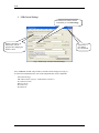
DETEXI Network Video Management System 5.5 EXPAND YOUR CONCEPTS OF SECURITY DETEXI NVR – Network Video Recorder The DETEXI NVR supplies the basis for video management, monitoring, analysis, and recording. Allows centrally manage and configure the network video products. USER GUIDE September 2008 Canada ON, Toronto, www.detexi.com DETEXI Network Video Management System EXPAND YOUR CONCEPTS OF SECURITY Table of Contents Introduction ................................................................................................1 What is NVR?......................................................................................................................................... 1 NVR Setup program ..................................................................................4 1.NVR General Settings......................................................................................................................... 5 2. NVR Cameras Setup ........................................................................................................................ 14 3. NVR Users Setup.............................................................................................................................. 27 4. NVR Tasks........................................................................................................................................ 31 5. NVR IO Devices ............................................................................................................................... 39 6. NVR Monitor.................................................................................................................................... 40 7. NVR Reports .................................................................................................................................... 41 Supplementary Software .........................................................................42 Network of NVRs......................................................................................44 Building NVR Domain .............................................................................45 How to set up an NVR as a member of Domain Network .................................................................. 46 How to set up NVR Domain Controller .............................................................................................. 47 Updating Camera lists across Domain ................................................................................................ 49 Updating User lists across Domain ..................................................................................................... 50 Troubleshooting across Domain ......................................................................................................... 51 Technical Information about TCP Ports for NVR................................51 5.5 NVR Introduction What is NVR? NVR stands for Network Video Recorder. NVR is a collection of hardware and software components that enables full digital, live, and recorded video surveillance over the Internet or Local Network from any connected computer. NVR consists of three major components: NVR device – is an intelligent storage and authentication server. In theory it can have unlimited number of IP-video/audio suppliers (such as IP-cameras, Digital Video Recorders, or IP-Servers) logically attached to it. Any device that is attached could be used by NVR. Video/audio source or source of the remote event (motion events or remote I/O port event) are examples of attached devices. NVR is also an authentication server for the workstations with Remote NVR Client. Remote NVR Client – a software that can be used to see live video/audio, control cameras, search archive database and playback the archive. IP-Video Device – supplies video/audio to the rest of the system. NVR device structure (in full configuration): NVR Services - Authentication Server - Recorder - FTP Server - Touring module Remote I/O Listener (Click on “Start Test”, and the “Port Test” window will appear (Fig. a.). - Check Alive module - Check Drive Module (It is used for testing purposes) Fig. c. Alarm Central - - Authenticates remote users connected to NVR through the Remote Client or Archive Viewer - Creates statistics about the remote users connections - Writes information from each video input in to the video archive according to the schedule - Receives FTP-streams from cameras (if set) and writes information in to the video archive - Raises an alarm when it receives an alarm sequence from camera - Moves the camera according to the tour schedule - Monitors remote inputs on I/O block of the camera - The main purpose are to test for correct Hardware and Software settings - Port test provides information about the camera that is sending data (Data could be just the connection signal or the signal about any alarm events.) Fig. b. - Checks to see if camera is online and video inputs are active - Checks to see if there is enough space for the NVR Video archive - Also checks the Archive Storage Path - Responsible for raising alarm using: - Voice - Phone (analog line with voice modem installed) - E-mail (Note: Sender name must be put in double quote). 1 NVR - Startbar module Port Listener NVR Socket Server - NVR Remote Control Server - Internal service to start/stop other NVR’s services - Monitors all local alarm devices - Internal service to support remote TCP/IP access to the NVR - Internal service for intercommunications between NVRs Fig. a. Alarm Listener Fig. b. Port Test Window NVR Interactive Modules - NVR Setup module - Billing Module - NVR Archive Viewer - NVR Client - Remote NVR Client module - Responsible for the setup information for all NVR’s services and components - Supports billing information about user and produces reports/bills about user activity - Searches and plays back video information from NVR’s archive - Live cameras view, cameras control, and playback the archive - Same as NVR Client after successfully receiving authentication from Remote NVR Site Fig. c. NVR Check Drive NVR Supplementary Software - Port-Mapper module - Responsible for mapping some ports to another IP addresses and ports (usually works as a service) Remote NVR Client structure: - Remote NVR Client module Remote Archive Viewer Module 2 NVR IP-Video Device: IP-Cameras - Axis IP-Cameras - SONY IP-Cameras - JVC IP-Cameras - ELMO IP-Cameras - IDVIEW IP-Cameras IP-Servers - Axis IP-Servers Digital Video Recorders - EDR400 - ERNITEC (DigiOp) NVR Network consists of several NVRs that are logically attached to the main NVR (NVR Domain Controller). Thus, it is possible to control every NVR remotely from the domain controller. NVR services can be managed from the “Control Panel” by choosing “Administrative Tool” window and selecting “Services” from the pull down menu (Fig. 1.) Fig. 1. Services As it is depicted on Fig .1., NVR Start Bar service has automatic Startup Type. In this case NVR activates as soon as computer is on, even before the login. Since NVR StartBar runs as a service, it also starts/stops all other NVR components as services. 3 NVR NVR Setup program The heart of the Network Video Recorder is the NVR Setup program. This is where the setting for all modules is done. NVR Setup program deals with certain components and sets specific properties for each of them. Major components of the NVR Setup program are as follows: General: which in turn consists of the following sub-components: • Global settings • NVR Locations (only for “NVR Domain controller”) • Camera location • Voice setup • FTP server • Advanced Cameras: which in turn consists of the following sub-components: • Camera list • Cameras setting • Security and Alarm • Description • Recording - Schedule setting - Motion setting • Tour (for PTZ cameras only) - Setup tour - Setup schedule Users: which in turn consists of the following sub-components: • User information • Groups of cameras • Billing information and restrictions Tasks: which in turn consists of the following sub-components: • Action - Record Camera - Move Camera - Control Relay - Control Tour • Notification - Network Client - Phone - Email - Speak Monitor: which in turn consists of the following sub-components: • Camera ID • Camera name • Alarm status • Touring status • Alive status • Recording status Report Components and sub-components of the NVR setup system will be investigated in the following sections. 4 NVR 1. NVR General Settings If checked, will connect camera immediately (Used in Recording) Database Path has to be defined first. Exit the program after changing the Database Path. Synchronize if any changes have been made. Fig. 2. NVR Setup →General→Global Settings Press “General” on NVR setup window to start the General setup process (Fig. 2.): As it has been mentioned before, each of the components has its sub-components. 1.a. Global Settings 1.b. NVR Locations (only for “NVR Domain controller”) 1.c. Camera Location 1.d. Voice Setup 1.e. FTP server 1.f. Advanced 5 NVR 1.a. Global Settings Archive Storage – controls the video data retention time, the minimum space allowed for storage on the drive(s) and whether or not to overwrite the oldest information when the drive has reached its minimum available space. Detailed overview of the archive storage is provided in Fig. 3. Data retention time Archive Storage Minimum free drive space Fig. 3. Recorder should stop/overwrite, when minimum free space reaches The following is a list of Archive storage contents: 9 9 Path Keep information for (days) Controls the duration in which the information is kept in the archive. The space required for the archive, and the number of frames per second, which will be received from all cameras in the network, should be calculated according to the user’s requirements. 9 If free space less than (stop saving/overwrite) The user has the opportunity to choose the time in which, overwrite of the data should take place. The example presented in Fig. 2 shows a retention rate of 20 days. When drive space falls to 3 GB free (3000 meg.), program overwrites the oldest data. 9 Use Temporary space Effective if the archive is stored on a network device. In this case this checkbox should be checked. The following is a list of Global settings’ other attributes: o Task Executed when - Writing error When writing error in archive occurred, the selected task from the pull down menu will be executed. - Drive limit reached If Drive limit (free space allocated in archive storage) is reached, the selected task from the pull down menu will be executed. Note: If a task is already selected from the pull down menu, to deselect it, press delete on the keyboard. 6 NVR o Port to Listen Port number used by all clients to connect to the Server. o Connect camera immediately - If checked, selected camera’s view will be shown immediately (The camera view on the recording page) - If unchecked, it gives the opportunity to the user, to connect/stop the selected camera’s view (cameras “recording page” Fig. 14.). o Resolve IP addresses Attempts to resolve the client IP address for statistical information. Use of this option is not recommended (due to its prolonged nature). o Login/Logout task If a task is selected from the pull down menu, it will be executed at login/logout. For instance if a sound notification task has been made and used in this part, that sound notification will be executed at entering and exiting the system. Note: If a task is already selected from the pull down menu, to deselect it, press delete on the keyboard. o Database path o SCADA path Supervisory Control And Data Acquisition path o NVR Controller Settings – This setting could be used when one needs to become part of the NVR network. The NVR Domain Controller address and port are to be provided in this part (For more information, please refer to “Building NVR Domain” section of this document. If any changes have been made during NVR setup process, SYNCHRONIZE button must be clicked. 7 NVR 1.b. NVR Locations (only for “NVR Domain controller”) When a request to connect to Domain controller is sent, this request can be: • • Either from a computer that is sending a connection request from within the same LAN (local IP address is used) Or from a computer that is sending a connection request from another LAN (external IP address is used). For more information please refer to How to set up NVR Domain Controller section provided later in this document. Fig. 4. NVR Setup →General→ NVR Location →Controlling Fig. 5. NVR Setup →General→ NVR Location→Monitoring 8 NVR 1.c. Camera Locations Setup “Location Name” and reference to “Location Map” if one exists. Map button on “Camera Locations” window Fig. 6. NVR Setup→General→Camera Locations Reference to this location can be made later in the NVR Cameras Setup (Description: Section 2.d.). Note: If user has assigned cameras to a map (done in section 2. d.), - Click on Map button on the camera locations window to view the list of assigned cameras Drag and drop them on their respective place on the map. Save and Synchronize As a result, MAP button will be enabled on the Remote NVR Client module main page. 9 NVR 1.d. Voice Setup Voice Setup button (Fig. 7.) – These settings are not only for voice, but also for phone and e-mail on alarm. Voice Setup button brings up Alarm Server voice configuration dialog box (Fig. 7.1.) Voice test MUST be clicked if any changes were made to voice setup (Save) Fig. 7. NVR Setup→General→Voice Setup Fig. 7.1. Alarm Server Voice Configuration dialogue box 10 Click on this button brings up Alarm Server Voice Configuration window (Fig. 7.1.) NVR 1.e. FTP Server FTP Server receives ftp-sequences from the cameras (AXIS, JVC and SONY cameras only). For JVC and SONY cameras, ftp-sequence is treated as an alarm sequence. FTP-client settings must be setup inside the cameras in conjunction with FTP Server settings. In order for the FTP Server to work properly one needs to setup the path in the “Images path for FTP Server” field for each camera (see cameras, Fig. 11.). The path for each camera server (or camera) must be unique and created before the setup can proceed. Server must be configured after the installation. User setup must be done after the server configuration (Fig. 8.). Note: User must define “Root Directory”; this implies the creation of Root Directory on hard drive. Fig. 8. NVR Setup→General→FTP Server Home directory could be the absolute or the relative path. If Home directory is the absolute path, the destination directory will be Home directory + Directory inside the Camera If Home directory is the relative path, the destination directory will be Server Root directory + Home directory + Directory inside the Camera Destination path must be in the path field of the “Images path for FTP Server” field (see cameras, Fig. 9. shown later in document). FTP Server could be started when cameras database is not empty (refer to section 2 of this document), Root Directory is defined, and setting is completed (Fig. 9.). 11 NVR Fig. 9. NVR FTP Server dialogue box To setup FTP-clients inside the cameras, see the camera manual. NVR software has special needs for the “image file name” format settings. Some of which are as follows: - SONY cameras: “image file name” must have name “asony” with the suffix “Date/Time”. - JVC cameras: “image file name” must have name “alarm_jvc”. - AXIS cameras: for continuous uploading “base file name” must be “cam1_image” or “cam2_ image” or “cam3_ image” or “cam4_ image” with “Date/Time Suffix“ selected. - AXIS cameras: for uploading in case of alarm “base file name” must be “alarm_cam1”, “alarm_cam2”, “alarm_cam3”, or “alarm_cam4”. To stop the FTP Server, select “Exit” from the menu (Fig. 9.). 12 NVR 1.f. Advanced By clicking on the “Advanced” tab in the GENERAL window, you will be able to set up some templates for the Recorder. Those setting and templates will be used tohelp you to create the “Recorder schedule”. Proxy Settings panel If a company uses web-proxy server that requires authentication to get to the Internet, proxy setting must be done in this panel. Get current button helps to get the following information: • Current domain name • Computer name • Current user name If “Disable Recorder Load Balancing” is checked< the NVR will always start only one instance of the Recorder (by default the NVR loads as many instances as many CPU cores is presented) General Settings panel - Backup Æ backups NVR general setting - Resrore Æ restores previously saved settings. Current Video Codec settings is used by internal automated conversion procedure in order to create an AVI file from the alarm sequence when client requests is (by pressing F12 on the Client side) User can select a language (to enable, restart NVR Setup program) User can get the information about has copy of the DETEXI NVR Fig. 10. NVR Setup→General→Advanced 13 NVR 2. NVR Cameras Setup To setup cameras, the “Cameras” tab on the NVR Setup Window must be selected (Fig. 11.). As it has been mentioned before, each of the components has its sub-components. Sub-components of the Cameras are as follows: 2.a. Cameras list 2.b. Cameras settings 2.c. Security and Alarm 2.d. Description 2.e. Recording 2.f. Tour (for PTZ cameras only) 2.h. Camera Tasks Fig. 11. NVR Setup→Cameras→Cameras Settings And “Sub-cameras” button 2.a. Camera list Add, Dup, Save, and Delete buttons are provided to enable the user to add, duplicate, save, or delete cameras respectively. • User must “Add” cameras to its camera list. In order to do so, click on Add button and fill out the camera information in the spaces provided on “cameras settings” (for more details refer to the next section). • To speed up the process to create cameras, an existing camera can be duplicated. First choose an available camera and then click on “Dup” button (Fig. 11.d.). The duplicated camera will have the same specifications as the original camera. Any changes can be made to the duplicated camera. • Save the new camera using the “save” button. 14 NVR • In order to delete a camera, select a camera from the list of existing cameras, and click on the Delete button. Cameras can be sorted in a camera list. To start the sorting process, double-click on the camera list header (Fig. 11d) After double-clicking on the camera list, select any camera and move it up/down (Fig. 11.e.). To save the sorted list, click on “Save cameras order” button (Fig. 11.e.) To cancel the changes click “Cancel” (Fig. 11.e.). 2.b. Cameras Settings Contains the following parameters that should be set: • • • • • • • • • • • • • • • • • Camera name Type Address and address port Select a non-standard port number if the camera is setup to listen to a non-standard port Note: By default all cameras listen to port 80. In this case you can leave “0” in the field Proxy type Internet access type, set to “Direct” if HTTP proxy is not used. Some of the proxy types are listed bellow: - Use Default - Direct - Named Proxy - From the WEB - Use as External Address If a proxy is used, “Direct” method can also be used in most cases. Proxy address and Proxy port Proxy address/port setups Flip Image It is sometimes necessary for Sony cameras. With PTZ Check Alarm Used by “Remote I/O Ports Listener”, if unchecked, “Remote listener” does not check the status of inputs on this camera. Exclude from Recording Recorder software uses this option. If checked, “Recorder” software does not see this camera. Sound This box needs to be checked if an Axis 2191 sound module is attached to camera. Stop touring while active Stop touring if any client is trying to connect to camera. Restore for Recorder Restore image settings for camera, if client has changed it. Image size: initial size of images when connection to camera has been established. Max FPS on write Max FPS on Request Images path for FTP server This setting is used for FTP Server only. Should be unique for each camera It must have the same setting as “FTP Directory” path inside the camera (camera that is FTP-ing images). Position on close Used for JVC Cameras, returns camera to one of the preset positions (if setup) upon leaving the camera. 15 NVR • • • • Number of sub-cameras Defines the number of video-inputs this device has. Alarm inputs Defines the number of device Input ports. Alarm outputs Defines the number of device Outputs ports. Alarm ComPorts Defines the number of device COM-ports ports. • Sub-cameras Tab It is used to set sub-cameras parameters for video servers. (Fig. 11.) 9 Number Number of sub-cameras 9 Active Reflects if sub-camera is connected to the video input 9 PTZ Defines which sub-camera has Pan/Tilt/Zoom capability. 9 Alive Defines if it is necessary to check “video-signal-lost” for sub-camera • Alarm Inputs Tab It is used to set device Inputs’ properties (Fig. 11.a.). 9 Input number 9 Name Any unique name, (If the standard names are not preferred) 9 Normal Status Open/Closed. • Outputs Tab It is used to set Outputs’ properties (Fig. 11.b.). 9 Name Any unique name, (If the standard names are not preferred) 9 Output number 9 Normal status ON/OFF 9 Behavior If “Toggle”, it will work similar to a light contact. If “Momentary”, it will work similar to a door contact. 9 State on close Unchanged, light must be turned on/off manually. ON, light will turn on automatically upon leaving the camera. OFF, light will turn off automatically upon leaving the camera. • ComPorts/MUX Tab Sets up the type of multiplexer attached to one of the video COM ports. (Fig. 11.c.) 9 ComPort number 9 Multiplexer Defines device type that is connected to the selected Com-Port 9 Sub-camera Defines video input associated with the selected Com-Port. Note: A special setup must be done inside the Axis server to make the multiplexer work properly. 16 NVR Fig. 11.a. “Alarm Inputs” button Fig. 11.b. “Outputs” button Fig. 11.c. “ComPorts/MUX” button Note: Also, setup User name(s) and password(s) in the “Security” table (This depends on the individual camera settings. Usually Axis cameras require this setting.) Double click here to start sorting the cameras (Fig. 11.e.). Get appropriate driver to deal with this device Fig. 11.d. 17 NVR Move Up Move Down “Cancel” to go back to Fig. 9d. Save Select a camera to move. Fig. 11.e. Sorting cameras For SONY and AXIS cameras it is recommended to use “Determine camera driver” button. You need to setup only name, type, address and port and proxy type for the device and press “Determine camera driver” button. If device has a password and you have not set it jet you will be asked about it and the password will be saved in “names and password: fields (see Fig.12). System will connect to the device and bring in all the necessary information about the device. 18 NVR 2.c. Security and Alarm Fig. 12.NVR Setup→Cameras→Security and Alarm • Names and Passwords, for access to each camera. • Actions on Alarm: - Check status task, user can select a task from the pull down menu to be executed when camera status changes (checks the physical status of the camera, if any problem is detected, executes the selected task). - FTP alarm task, user can select a task from the pull down menu (This is used when Images path for FTP server is set for a camera.) Images path for FTP server located at the “Cameras settings” is used for FTP Server only. It should be unique for each camera, and must have the same setting as FTP Directory path inside the camera (the camera that is FTP-ing images) Note: If a task is already selected from the pull down menu, to deselect it, press delete on the keyboard. • Number of sub-cameras, sub camera number can be selected from the pull down menu. User can then select any of the following choices for a chosen sub-camera: - WAV File phone message - Location to play message from - Play Alarm, if checked, select and perform one of the following in order to create a default message to be played when “Message can be changed Automatically” is checked in “Task” (for more information please refer to part 4.e., 4.g., and 4.h. of this document): 9 Message, user can create a message. 9 WAV file, user can select a message from previously saved material. 19 NVR 2.d. Description Fig. 13. NVR Setup→Cameras→Description When a specific alarm event occurs, information provided in Description window will be used to inform the user of the alarm event (Fig. 13.). Description window contains the following information: • • • • • • Camera location: The location in which camera resides. Customer name Site address Site sector Contract number Special instructions Note: For a camera to be assigned to a map, - Select a camera from the list - Select a location, from the camera location pull down menu (The available locations were created in Section 1. c. of this document). - Save and Synchronize - As a result, the chosen camera will be assigned to the selected camera location. - User will be able to put each camera in its respective place on the map (For more information please refer to Section 1. c. of this document). 20 NVR 2.e. Recording Recorder is part of the NVR software. It is responsible for getting the video streams from the cameras according to the schedule (refer to schedule box in recording). Also, it writes the information into the archive. Recorder can supervise AXIS, JVC, SONY, Panasonic, Pixord, IDVIEW, EverFocus (EDR400), ENRITEC (DigiOp), Convision and some other Internet-cameras. Connect/Stop Schedule settings Schedule lines Zoom/Move by clicking on the picture Different Motion Settings could be defined for each schedule line. Time restriction setup Alarm/Motion Settings Image and position setup Check motion in every “Motion-step” frame Number of frames to write AFTER frame with motion detected Fig. 14. NVR Setup→Cameras→Recording Keep in mind the “alarm-on-motion” always makes recording by itself with number of frames at least “Pre-alarm”+”Post-Alarm” even if “Execute Task” is not defined. This will prevent interrupting soft-alarm recording by I/O port or by any other task for “Dwell” seconds. Number of frames to write AFTER “Alarm-on-motion” occurs. System will not detect next soft-alarm until all post-alarm frames are written. This will prevent interrupting softalarm by the next soft alarm. 21 NVR Many lines can be added to the schedule for each sub-camera. It is worth mentioning that, lines are the scheduled recordings, located at the schedule box (Fig. 14.). Different sections are to be set for each line of the schedule (Fig. 14): 1. 2. 3. 4. 5. 6. 7. 8. Schedule section - Click on “Add”, “Save”, or “Delete” buttons to add, save, or delete schedules respectively. Connect/Stop Button - Gives permission to Start (connect)/Stop recording - This option is enabled on the “cameras recording” window, when the option “connect camera immediately” is not selected (Fig. 2). - This feature enables the user to have the ability to setup a camera and record, while not mounted. Motion settings - Please refer to Motion setting section provided later in this document (Fig. 15.). Time restrictions section - No time restrictions (recording at all times) - Restricted between (records only on selected days between specific hours (FROM/TO). - Take shots between (records predefined number of shots on selected days between specific hours (FROM/TO). Image and position setup section - Image size - Recording frequency (FPS): number of frames per second - Image compression Move to position section - “Pan/Tilt/Zoom” OR “Preset”: position that camera will move to, before recording starts Motion and Alarm section - Motion detection - index file by “frames with motion” will be created for playing back from the archive. Only “frames with motion” are always recommended. To create the index file, program uses “Motion step” and “Post motion” settings. Usually “Motion step” and “Post motion” should be 1/2 or 1/3 from “FPS” value. In order to detect motion, Recorder uses “Motion Settings” parameters (Fig. 15.). - Motion only – places “frames with motion” in archive (could save archive space). It is possible to move the camera to predefined “Pan/Tilt/Zoom” OR “Preset” position when motion is detected. - Move Camera on Motion area (if checked): o PTZ Æ camera will be moved to this position when motion is detected. o Preset Æ camera will be moved to this preset position. o Zoom area with motion Æ camera will be moved to the area where motion is detected with the predefined zoom. o Reset camera position → indicates that, camera should be pointed to the initial PTZ or Preset position (if set). - Alarm on motion – raises an alarm if motion has been detected. The raised alarm will be selected from the “Execute Task” pull down menu. Note: If a task is already selected from the pull down menu, to deselect it, press delete on the keyboard. - Alarm on Input ports – forces to detect alarm on cameras I/O block, and executes the selected task (actions and notification) that has been chosen from “Execute task” pull down menu (Fig. 14). These alarms are bounded to TASKS (for more information on Tasks, please refer to section 4). Note: Pre-alarm (frame), Post-alarm (frame), and Dwell (Second) are used for frame settings. Connection type section - Use locally (without proxy)– forces the “Recorder” to connect to camera without using proxy setting. 22 NVR Motion Settings Disabled sub-region To move, click inside the ROI and drag Active subregion To resize, click on the corner and drag Fig. 15. Motion Settings This screen enables the user to setup motion detection parameters for each line of the schedule (Fig. 15.). o Draw ROI In order to draw ROI (Region-of-Interest), start with left-top corner, press left-mouse-button and drag mouse down to the right. A red box will appear on the picture that is referred to as ROI. o Enable/disable sub-regions To enable/disable sub-regions, press “ctrl” and left click simultaneously. Only the motions inside the active sub-regions are considered by the system. o Clear ROI Double click on the screen outside the boxes or press right mouse button to bring up popup menu. o Move ROI To move ROI click inside the region of interest and drag the box. o Roughness and sensitivity adjustments Use the scroll bars to adjust the roughness and sensitivity of the motion detection. Vertical red and yellow stripes indicate alarms inside the red and yellow ROI respectively. 23 NVR 2.f. Tour (for PTZ cameras only) Touring can be setup and started for any PTZ-capable AXIS, JVC, or SONY cameras. This must be done according to specific schedules. In order to enable the “Tour” option, check the “With PTZ” box on the Cameras settings page (Fig. 11.). Cam Tour application is a part of NVR software that provides all the necessary settings for touring. In order to setup a tour, user must: a. b. Setup tour Setup schedule Fig. 16. NVR Setup→Cameras→Tour→Setup Tour a. Setup Tour • • • • • The first step to setup a tour is to select a camera from the cameras list (Fig. 16.). Then click on add tour button. Camera can be moved by clicking on the image or zoom in/out to point the camera to a specific region. When the camera is pointed properly, click on “add position” button, and enter the number of seconds you wish the camera to stay at that position. Note: Multiple points can be selected by repeating the latter procedure. A tour can consist of many different positions. When all the positions are entered, click on “Save tour” button. At this time a name must be chosen for this tour. Note: “Build Loop” is an option provided by setup tour window. When selected, system will automatically add additional positions to the path we made. This will enable the camera to have a loop shaped movement (going from left to right and vice versa). You can test a tour that you setup, by clicking on “Test Tour” button. Note: A tour can also be setup by using preset positions (If preset positions are already created for the camera). 24 NVR 2.h. Camera Tasks This allows user to setup tasks which can be remotely executed by the Remote Client when the appropriate camera (or video input) becomes active on the single-screen of the Client . You just need to move (see Fig.16a) all the necessary tasks from “Available Tasks” list to “Linked tasks” list. Fig. 16a. NVR Setup→Cameras→Tour→Camera Tasks 25 NVR b. Setup Schedule Any of the previously setup tours, can be used in the tours schedule. Sub-cameras can be added to the tour schedule by selecting add button. The setup schedule setting also provides delete and save option (Fig 17.b. & 17.d.) To Setup a schedule: • Click on “ADD” button. • Select “No time restrictions” or “Restricted Between”. • Select a previously setup tour from the “Tour” pull down menu. • “Use Locally (without proxy)” check box: - Check- if NVR and cameras are located on the same local network (require internal connection) - Do not check- if NVR and cameras are not located on the same local network (require external connection). Note: This option only appears on the camera’s” setup schedule” when the selected camera has existing address and proxy address (Fig. 17.a. &17.b.). If the camera does not have proxy address, this option will not be available (Fig. 17. c. & 17.d.) • Click on “Save” button. Address “Use Locally (without proxy)” check box. Proxy Address Fig. 17.a. Cameras settings Fig. 17.b. Setup Schedule Address “Use Locally (without Proxy)” check box does not exist for this specific camera. There is no proxy address for this specific camera. Fig. 17.c. Cameras settings Fig. 17.d. Setup Schedule 26 NVR 3. NVR Users Setup To setup users, click on “Users” option provided on the NVR Setup Window. As it has been mentioned before, each of the components has its sub-components. The sub-components of the Users are as follows: 3.a. User information 3.b. Groups of cameras 3.c. Tasks 3.d. Billing information and restrictions 3.a. User Information Fig. 18. NVR Setup→Users→User Information Add, Dup, Save, and Delete buttons are used to add, duplicate, save, or delete users respectively. User information page is used, to assign passwords, user rights, and cameras to the user (Fig. 18). The following should be setup in the “Users” dialog box: - User name - Password - Number of active users (at the same period of time) - Exclusive PTZ: Allows user to forbid control of the camera to other users - Maximum connection time for any user - Cameras list available to the user, and user’s rights in accordance to each camera - Users type - Login task, can be selected from the pull down menu to be executed when user logs in. - Logout task can be selected from the pull down menu to be executed when user is logged out. Note: If a task is already selected from the pull down menu, to deselect it, press delete on the keyboard. Note: If Login task and/or Logout task are not selected in User Information window, system will execute the selected Login/Logout task from the General → Global Settings. If there is no designated task for login/logout in global settings, system will not issue any login/logout tasks. 27 NVR There are two kinds of users available: Master User and Exclusive Master User. While an exclusive master user selects a camera, that camera will not be available to other users. It is worth mentioning that “Exclusive Master User” has the ability to halt any active user. To assign a camera to the user, camera has to be moved from the available cameras list to the assigned camera list by clicking on “>” button. Important Note: If you are going to be a part of the NVR’s Domain Network, you have to create “Exclusive Master User” without any cameras attached to it. Its username and password will be used for authorization in intercommunications between NVRs, inside the NVR’s Domain Network. For each assigned camera, assign user rights, and sub-camera settings. This is done by selecting line from Video-in combo box and setting video-in properties. Video-in has the following properties: • Can use (activate/inactivate the video input) • Can PTZ (allow/forbid to control the camera connected to this video input) • Max FPS (if not zero restricts MAX FPS from this video-input, for this particular user) 3.b. Groups of Cameras To setup Groups of cameras for a user, select “Groups of Cameras” tab. (Fig. 19.). Several cameras can be grouped together to facilitate simultaneous display. 6 4 1 2 3 5 Fig. 19. NVR Setup→Users→Groups of cameras In order to create groups of cameras for each user, I. Select a user from the “Users list”. II. List of the cameras assigned to this particular user is shown in the “Available” list. III. Click on “Add” button at the bottom of the “Group List” IV. Enter a particular name into the “Group Name” space Note: Any camera can be selected from the available list and moved in to the “Selected” list. V. Click on Save button VI. Click on Synchronize button Add, Del, or Save buttons can be used to add, delete or save group settings respectively. 28 NVR 3.c. Tasks Fig. 19a. NVR Setup→Users→Tasks It is possible to assign tasks to the user. It allows the user (Remote Client) to execute assigned task right on the NVR 29 NVR 3.d. Billing Information and restrictions To setup restrictions for the user “Billing Information and Restrictions” option is provided (Fig. 20.). Fig. 20. NVR Setup→Users→Billing Information and Restrictions The information in “Full Name”, “Time block” and “Fee” fields are selected from the settings in the “Billing module”. Up to three restricted intervals are available when the user is banned to reach the Server. 30 NVR 4. NVR Tasks Tasks are used in: • Monitoring section of the “NVR Locations”, when an NVR does not respond to Domain controller (Section 1.b. Fig. 5. and How to set up NVR Domain Controller). • Alarm section of the cameras “Recording” (Section 2.e. Fig. 14.). - Execute task on (Alarm on Motion) - Execute task on (Alarm on Input ports) • Global Settings - Task Executed when writing error - Task Executed when drive limit reached - Login/Logout Task • Camera’s Security and Alarm - Check status task - FTP alarm task • User’s Information - Login task - Logout task Add, Save, or Delete buttons can be used to add, save or delete Tasks respectively. In order to create a Task: • Click on Tasks button provided on the NVR Setup window (Fig. 21.). • Click on Add button. • Choose a name that best describes the new Task (Task Name: e.g. Task). • Provide a description for that specific Task (Description: testing). • Save and synchronize Task name and Description A Task Right Click here in order to create new Actions or Notifications Left Pane Fig. 21. Tasks (e.g. Task) In order to be able to set new actions or notifications, right click on the space provided on the Tasks window (left pane, Fig. 21.). As a result, user will be able to create multiple actions or notifications; they are as follows: New→Action 4.a. Record Camera 4.b. Move Camera 4.c. Control Relay 4.d. Control Tour New→Notification 4.e. Network client 4.f. Phone 4.g. Email 4.h. Speak 31 NVR New → “Action” 4.a. Record Camera Click here to bring up PTZ control dialogue box Fig. 22. New → Action →Record Camera Action (Record Camera) Setup: • • • • • • • • • • Camera: Select a camera for this action. Set camera in position - Pan/ Tilt/ Zoom - Or Preset Record - Image size - Compression - FPS - Frames - Sec. Take Alarm shot: For PTZ cameras; if checked, takes alarm shots. Delay (ms): Since actions and notifications in a task take place simultaneously, camera could be pointing in any direction other than the region that alarm shot should be taken from; thus a very small delay time might be required to assure uniformity of task execution. Reset camera in position - Pan/ Tilt/ Zoom - Or Preset Connect/Stop: When camera is selected, click on connect button in order to connect to that camera (click on stop button to disconnect from the selected camera). Show Locally Uninterruptable alarm Use local connection 32 NVR 4.b. Move Camera Click here to bring up PTZ control dialogue box Fig. 23. New → Action →Move Camera Action (Move Camera) Setup: • • • • • • Camera Set camera in position - Pan/ Tilt/ Zoom - Or Preset Dwell time(s): The time in which camera stays in a selected position. Reset camera in position - Pan/ Tilt/ Zoom - Or Preset Connect/Stop: When camera is selected, press connect button in order to connect to that camera (press stop to disconnect from the selected camera). Show Locally PTZ Control Zoom in Direction control tool Fig. 24. PTZ Control Home Position Zoom out Choose pre-set position from the pull down menu 33 NVR • • • • • Pan/ Tilt/ Zoom Get PTZ: When clicked, provides the PTZ value of the position that camera is pointing to. Set PTZ: Can be used in order to change PTZ values. Zoom IN/OUT Go to Preset: Choose a preset position from the pull down menu and click on “Go to Preset”; as a result camera will point to the selected preset position. Home position Direction control tool: Can be used to control the direction of the camera towards Right, Left, Up, and Down. • • 4.c. Control Relay e.g. 5 sec. Fig. 25. New → Action →Control Relay Action (Control Relay) Setup: • • • • • • Relay: An output that can be selected from the pull down menu (e.g. light). Turn On: If checked, the selected output turns on. Turn Off: If checked, the selected output turns off. Activate Dwell time(s): the time in which the selected output (e.g. light) stays on/off. Reset relay: If checked, resets relay to its previous state. 34 NVR 4.d. Control Tour Start tour Stop tour Fig. 26. New → Action →Control Tour When “Start tour” is selected, a pre-selected tour will start. When “Stop tour on camera” is selected, the tour that is running will be stopped. Action (Control Tour) Setup: • • • • Start Tour: when selected, a camera and a tour must also be selected from the pull down menu Stop Tour on camera: when selected, a camera must be selected from the pull down menu Reset touring after (e.g. 25) second(s) Uninterruptable tour action • Use local connection (This option exists only for specific cameras). 35 NVR New →“Notification” 4.e. Network Client Message box Fig. 27. New → Notification →Network Client A sample text message that is sent to a client is depicted in Fig. 27.1. Notification Via Message Setup: • • • • • • • Address: address of the client that Domain controller wants to send the message to. Port: Client port number. Proxy address Proxy port Send always: If checked, sends the message to the client. Note: User can create multiple client notifications (network client) under one Task. At least one “Send always” checkboxes must be checked. Message: A text Message that will be sent to client when required (e.g. Domain Alex does NOT RESPOND). Message can be changed automatically: - If checked, an automatic default message will be send to the client. Thus, the text message that was written in message box will be ignored. - If not checked, the text message, which was written in the message box, will be send to the client (Fig. 27.1.). Fig. 27.1. Sample Message sent to client by Domain controller 36 NVR 4.f. Phone Fig. 28. New → Notification →Phone Notification via Phone Setup: • Location to phone message from • Phone/Pager to call • Number of attempts • Always call 4.g. Email Fig. 29. New → Notification →Email Notification via Email Setup: • Location to mail message from • Email address (es): Email address of the party, which the notification will be send to • Subject: Email subject. • Message: Email message that will be send to client. • Message can be changed automatically - If checked, an automatic default message will be send. Thus, the message written in message box will be ignored. - If not checked, the message, which was written in the message box, will be send as an Email notification message. • Repeat if unsuccessful (e.g. 2) times every (e.g. 30) sec.: Repeat the send process for a specific number of times. 37 NVR 4.h. Speak Message box containing Sample message. Fig. 30. New → Notification →Speak Sound Notification setup: • Location to play message from: Address of the location in which message will be played from. • Message can be changed automatically: - If checked, an automatic default message will be played. Thus, the message written in message box to be played as sound notification will be ignored. - If not checked, the message, which was written in the message box, will be played as a sound notification message. • Message: Message that can be played when required (e.g. Domain “ALEX” is offline). WAV file: Browse and select a saved WAV file to be played when required. 4.g. Composite Task A composite task consists of the other tasks, which could be executed according to the schedule inside the composite task. This allows you to execute different tasks (or skip the executing at all) at a different time. Composite task is a powerful instrument because it have schedule embedded in it and could initiate different actions in different time. 38 NVR 5. NVR IO Devices If you have appropriate license you will see “IO Device” tab and will be able to work with: - Gameport - IOBoard ET-PCI16IO - Paradox Spectra device You have to create right descriprion of the device you are going to use (see Fig. 30.a) Fig. 30.a. IO Device Setup. You can assign task to any event device could create. On receiving signal from the device appropriate task will be executed. 39 NVR 6. NVR Monitor Monitor allows the user to observe NVR components (Fig. 31.). Recorder is running (blue). It will be restarted if Check Alarm is stopped (red). Health Monitor button allows you to assign tasks to monitor NVR components Log Viewer button allows you to see log information about tasks Fig. 31. NVR Setup→Monitor During normal operation this window could be left open and available. The status of all the cameras that have been installed on the NVR can be seen on NVR monitoring window. The following information is displayed on the Monitor window: Camera ID number Camera name Alarm Status Touring Status Camera “Alive” Status Recording Status Module status and control panel are located at the bottom of the window. Note: The Modules at the bottom of the Monitor are not to be stopped by the user. The panel allows the user to select which module to run. By default ALL modules start at boot up and are monitored for operation. If, for some reason, the user stops a module and is selected to be monitored, it will be re-started by the Monitor in approx. 30 seconds. When a module is stopped, its title becomes RED. If a module is running, it becomes BLUE. By unchecking the box beside the title, that module won’t be automatically re-started by the Monitor. Un-checking the Monitor box disables the Monitor, thus modules won’t be automatically re-started and, upon re-boot, the NVR itself will not be re-started either. Note: It is recommended that the Monitor be active at all times. 40 NVR 7. NVR Reports This advanced feature allows the user to run reports that show when various users have been authenticated and logged on to the NVR. It displays date, time, and the host address. Searches can be made using the following criteria: - USER NAME HOST ADDRESS Date range Click Run to view the report. Fig. 32. NVR Setup→Reports 41 NVR Supplementary Software Port Mapper Setup Fig. 40. Port mapper To map a port use the Add/Delete/Edit buttons (Fig. 40.) After pressing one of those buttons, port mapping dialog box will appear (Fig. 41.). Fig. 41. Port mapping dialogue box Fill in the required information in the Port Mapping dialog box (Fig. 41.). To activate mapping CHECK the required port (Fig. 41.) and press the start button (Fig. 40.). To stop the program, use the “Exit” button only. (Closing the window will force the program to minimize itself). 42 NVR Note: In order to edit the line, stop (inactivate) listening to the port you want to edit. 43 NVR Network of NVRs There are two challenges that video surveillance systems are facing today, namely scalability and reliability. Large organizations that have multiple sites in local or remote locations could have from ten to over a thousand cameras to manage. The approach in the past was to have islands of standalone systems that required time consuming and inconvenient maintenance and management. Taking our cue from existing computer network topologies, a new and exciting approach to digital video surveillance management and control has been developed. We have developed the Network Video Recorder Domain model to address scalability and reliability. Digital video recording consumes a large amount of hard drive storage space. With a large amount of cameras sending information to the archive over a long period of time, the only way to adequately deal with the shear volume of files is to share the load over a distributed NVR network. The central administration point of this distributed network or domain is the NVR Domain Controller. NVR Domain Controller permits the following actions: 1. To consider the whole NVR Domain consisting of several NVR’s as one powerful NVR. Each particular NVR from the domain will be responsible only for recording its own set of cameras and searching its own archive. 2. NVR Domain Controller will authenticate all clients’ access (connections from computers viewing cameras) via the local area network, or the Internet. Domain Controller only needs to maintain the user list. It is not necessary to have a user list for each particular NVR in domain. This centralizes user access control and database management. 3. NVR Domain Controller allows us to consider each particular NVR in the domain like a computer without keyboard, mouse and monitor. The Igloo is a good example for this. We can have set of Internet addressable igloos we can remotely control and search. (See the IGLOO PDF included on your NVR CD for more information) 4. NVR Domain Controller makes the whole system highly scalable and capable to record from ten to hundreds of cameras. Just add one more NVR in the domain and assign a new set of camera to it. If you have two or more NVRs in different locales, you should explore upgrading with this module. 44 NVR Building NVR Domain Whether you have several sites or a single site with hundreds of cameras, you can now plan a security management strategy. You can create a set of NVRs by dividing cameras by groups, and assigning each group to a corresponding NVR. Each particular NVR is responsible for its group of cameras and carries the duty of recording, touring, and alarming functions. We use an NVR Domain Controller to manage the set of NVRs (Fig. 42.) Fig. 42. 45 NVR NVR Domain Controller gains knowledge of all NVRs in its domain, which in turn leads to the realization of the existing cameras in the corporate network. NVR Domain Controller can: Remotely Create and Update cameras list on any NVR in Domain Remotely Create and Update recording schedule for each camera Remotely Create and Update touring schedule for each camera Obtain and update remote User List from any NVR in Domain as well as support its own local user list. Remotely monitor any NVR in Domain Start and Stop any NVR’s component on any NVR in Domain Note: For security reasons, NVR Domain Controller can remotely connect to the NVR only after providing the appropriate username and password. How to set up an NVR as a member of Domain Network To have any NVR as a part of the NVRs Domain Network, configure NVR controller settings in the “Global Setting” (Fig. 43.) Set address and port number. Recommended port numbers are: 60000 or 60001 Register/Unre gister site Fig. 43. General → Global Settings Place IP address or IP name of the NVR Domain Controller in the space provided on “NVR Controller Settings” panel. Once the address of Domain Controller is set, enter location name (choose any) and click on “Register Site on Domain Controller”. Username and password will be asked if a connection to Domain Controller already exists. From this point NVR “introduces” itself to Domain Controller. At least one user must be set as “Exclusive Master User”. The Exclusive master user has to provide its name and password to the NVR Domain Controller administrator. Subsequently NVR Domain Controller administrator could accept/reject registration from a specific site. 46 NVR If the site is accepted, it becomes part of the NVR’s Domain Network. Once became a part of NVR’s domain Network, any changes on NVR in cameras table (edit/add /delete) will be mirrored on Domain Controller. Domain model depends on the connection (locally or through the Internet) between NVR and Domain Controller. This is important specifically while making changes to camera setting. For instance, if the connections to Domain Controller break temporarily, continue to work and Domain Controller will look after synchronization later. How to set up NVR Domain Controller Any NVR that holds the “Domain Controller License” could become NVR Domain Controller. NVR domain controller has to set one of its users as “Exclusive Master User”. Exclusive Master User has to provide its name and password to other NVRs (children) in domain. An NVR sends a request to get connected to Domain Controller. When the request is received by NVR Domain Controller, the information about the requester is shown in the Camera Server connect setting field (Fig. 44.). This information could be: • The address and port number of a requester that is within the Domain server’s NVR network (local network having internal address). • Or the address and port number of a requester that is from another NVR network (for communication between NVR Domain Controller and a particular NVR). The Red “NEW” on the NVR location window (Fig. 44.) indicates that NVR from a requester (e.g. Graphics) wishes to be part of NVR Domain controller. This request can be accepted by pressing ”Import” button or rejected by pressing ”Unregister” button. Note: Proxy address and port information exist according to the Internet setup of the requester. This is when the requester is using a setup, which uses proxy address and port in order to connect to the Internet. The following information about the communication between Domain controller and a requester is also provided on the NVR Location window: • Controlling - • Get NVR status Synchronize location: Remote location can be forced to synchronize, if some changes are made remotely. Restart remote OS Monitoring: uses the Tasks that are created in NVR Setup in order to take an action or issue a notification when required. - Check Alive: If checked, enables the use of a Tasks (Action or Notification) Interval for monitoring (sec.) Attempts (e.g. 2) each (e.g. 10) sec. Task when NVR does not response: can be selected from the pull down menu (e.g. Test, Fig. 5.). Note: The address in the Camera Server connect setting must be identical with the content of INTERNET Name or address field. 47 NVR Disable remote site. It is useful if there are technical problems connecting to this site. Changes to settings can be saved. Fig. 44. NEW connection request Information about the cameras from remote site is copied using this option. There are no restrictions about using this option. The following is a list of possible actions when a request to join the NVR is sent: Press “Import” button Æ request to join is Accepted Æ location will go to Normal Mode Press “Unregister” button Æ request is Rejected Æ location will be deleted Do not press any buttonsÆ Ignored Æ location stays in NEW mode If REMOTE NVR is in “Normal” mode, o o o System will keep up-to-date information about the remote cameras settings. Allows remotely updates (from the NVR Domain controller). Allows updating “users” information on the remote site. If REMOTE NVR is in NEW mode, o o NVR’s request to join the domain is not accepted. Domain Controller will not know camera database from the remote NVR. Connection from the Domain Controller to the Remote NVR is supported in both modes. One can control remote NVR’s components, and watch processes on the remote site. Note: Remote Site can be accepted at all times. Both sites could have Cameras, users and/or schedules list already created. 48 NVR Updating Camera lists across Domain If Remote NVR is in “Normal” mode, you can remotely update Cameras list. To do this, find remote location (e.g. Graphics), and change camera setting locally. (Fig. 45.) Remote Location Fig. 45. NVR Setup → Cameras → Cameras Settings 49 NVR Updating User lists across Domain Fig. 46. NVR Setup → Users → User Information If Remote NVR is in “Normal” mode, you can remotely update Users list. To update the USER, select the location that needs to be updated from the “User” table (Fig. 46.) First time users will be asked for the authentication information by the system (Fig. 47.) Fig. 47. Authentication window for Remote User (Always contains the name of the remote user, e.g. Graphics.) After successful authentication, the User List will be accessed from Remote Location. 50 NVR Troubleshooting across Domain When connection between ” NVR domain controller” and another NVR (child) in its domain is broken, the system has to have the ability to continue its work and do the synchronization later. In case of a “broken connection” between Domain controller and a remote site such as site “A”: 1. If o The whole situation is looked at from remote site “A” standpoint, o User (e.g. site ”A”) is still allowed to change its own site ⇒ NVR will go into “Synchronization failed” mode and will not update information across domain. Only Domain Controller can bring site “A” to “Normal” mode. Click on “Import” button in order to bring site ”A” into “Normal” mode (Fig. 44.) 2. If o The whole situation is looked at from “Domain Controller” standpoint, 9 Either, site “A” (Remote NVR) is in “Synchronization failed” mode 9 Or a “broken connection” between “domain controller” and site “A” has occurred ⇒ No update will be allowed to site “A". To synchronize Domain database with the remote database click on “Import” button for appropriate Remote Site (see “Import” button on Fig. 44.). Technical Information about TCP Ports for NVR List of TCP ports used by NVR by default: 20 21 23 2080 60000 60001 65235 To Guarantee the full functionality of NVR, administrator should open the provided TCP ports. In addition, if PortMapper is used, open all TCP ports, which are being used by it. 51