1
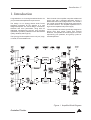
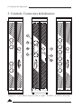
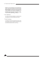
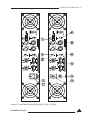
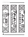
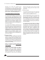
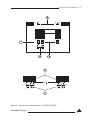
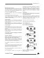
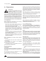
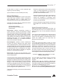
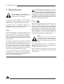
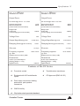
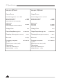
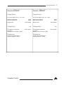
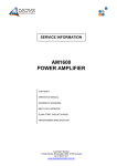
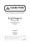
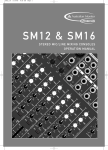
Professional Audio Amplifier
SY 400
SY 800
SY 1200
SY 1600
SY 400V
SY 800V
SY 6125
SY 4200
Operation Manual
IMPORTANT!
Please read carefully.
This operation manual contains important information
regarding safety precautions, installation, performance,
operation and maintenance of your Synergy-Series power
amplifier. You should familiarize yourself with the contents
of this manual before operating your amplifier.
Safety Precautions
and Labelling
The rear panel of this amplifier has a number of
markings and internationally recognized symbols
relating to the hazards and precautions that should
be taken when operating MAINS connected
equipment.
REFER SERVICING TO
QUALIFIED PERSONNEL.
NO USER SERVICEABLE
PARTS INSIDE.
The presence of a LIGHTNING FLASH with an
arrowhead contained within the boundaries of an
equilateral triangle is intended to alert the user that
dangerous uninsulated voltages may exist within the
amplifiers enclosure. These voltages may be of a
sufficient magnitude as to constitute the risk of an
electrical shock.
The user should not attempt to service the amplifier.
Only qualified and knowledgeable personnel familiar
with the internal workings of the unit should attempt
any repair, servicing or authorized modification to the
unit. The unit does not contain any parts which the
user can service or re-use in this or any other
product.
This symbol is reinforced with the text:
!CAUTION!
RISK OF ELECTRICAL SHOCK
DO NOT OPEN
The presence of an EXCLAMATION MARK
contained within the boundaries of an equilateral
triangle is intended to alert the user that there is
important operating and maintenance literature that
accompanies the amplifier.
!WARNING!
DO NOT EXPOSE TO EITHER
RAIN OR MOISTURE
If you are in need of special assistance and the
information you require is outside the scope of this
manual, please contact your nearest service agent
or Australian Monitor direct:
THE TECHNICAL OFFICER
AUSTRALIAN MONITOR
C/- AUDIO TELEX COMMUNICATIONS PTY LTD
PRIVATE BAG 149,
SILVERWATER. N.S.W. 1811
AUSTRALIA.
Local
International
Phone
(02) 9647-1411
61-2-9647-1411
Fax
(02) 9748-2537
61-2-9748-2537
Email
Internet
[email protected]
www.australianmonitor.com.au
The amplifier should not be operated in a situation
where it may encounter the entry of water, rain, or
any fluids. To expose the unit to the above conditions
may make the operation of the unit hazardous and
increase the risk of electrical shock.
Rev 2 16/06/04
Rev 3 26/06/04
Rev 4 28/06/04
Rev B 28/06/04
Features:
> Custom designed, 2RU heavy duty steel
chassis.
> Open, modular construction for ease of
servicing.
> Symmetrical layout - even weight distribution.
> High current power supply.
> High efficiency toroidal mains transformer.
> Binding post and 4 pole speaker output
connection (no 4 pole speaker outputs on
SY400V, SY800V, SY4200 & SY6125).
> Stereo or bridged operation (no bridging
available on SY400V & SY800V).
> Input signal strapping (loop through) connectors
> Balanced inputs and buffered attenuators.
> 1 Watt output indication (2.828 volts).
> 1 dB below output clip indication.
> Efficient front to back cooling.
> Dual, twin speed axial fans.
> Multi-role output fault indication.
> Front carry handles. Rear rack mount ears.
> Signal ground lift switch.
> Built in limiter circuit.
> High-quality, close-tolerance components
throughout.
(not available on SY6125).
Protection Features
> Suppression of inrush current at mains turn-on.
> Input muting at turn-on.
> Input overvoltage protection.
> Radio-frequency interference suppression.
> Short-circuit protection and indication.
> High overload mains fuse.
Australian Monitor
> Internal, independent DC supply rail fuses.
> Layout, grounding, decoupling and componentry
have been optimized to provide the user with
stability, reliability and longevity.
Contents
Page
1.
2.
3.
4.
5.
6.
Introduction
Controls, Connectors and Indicators
2.1 Front Panel
2.2 Rear Panel
Installation
Operation
Maintenance
Specification
5
6
7
11
14
16
18
20
List of Illustrations
Page
Figure 1. Block Diagram
Figure 2. Front Panel Layout(SY6125, SY1200, SY4200)
Figure 3. Rear Panel Layout (SY400, SY1600)
Figure 4. Rear Panel Layout (SY6125, SY4200, SY400V)
Figure 5.Top Lid Layout (SY6125, SY4200)
Figure 6. Speaker Connector Wiring
5
6
9
10
13
15
Introduction 5
1. Introduction
Congratulations on choosing Australian Monitor for
your professional amplification requirements.
The design of our Synergy-Series Audio Power
Amplifiers embraces all the aspects of a well
designed amplifier. The visual design, mechanical,
electrical and sonic parameters, along with our
dedicated manufacturing process, have all been
optimized to provide a professional tool that exhibits
quality, reliability and longevity.
The Synergy-Series amplifiers are 2 unit (3.5") high,
19" wide, rack mountable units.
Each channel of the amplifier comprises a balanced
active input with a buffered attenuator driving a
differential class A drive stage which in turn drives a
fan-cooled, class AB, BJT output stage configured as
an emitter follower. The amplifier operates from a
high current-capable linear power supply.
These amplifiers have been specifically designed to
deliver their high power output with minimal
distortion, and provide the critical degree of control
required by your speakers, at high duty cycles for
extended periods.
Figure 1 Amplifier Block Diagram
Australian Monitor
Figure 2
MIN
MIN
LEVEL-A
LEVEL-A
MAX
MAX
B
OVERLOAD
A
STATUS
MIN
LEVEL-B
MAX
MIN
LEVEL-B
MAX
MIN
Australian Monitor
OVERLOAD
B
STATUS
A
MAX
OVERLOAD
LEVEL-D
MAX
MIN
LEVEL-E
MAX
THERMAL
FAULT
POWER
OVERLOAD
F
STATUS
D
E
MIN
MAX
STATUS
SY 6125
LEVEL-C
LEVEL-C
C
SY 4200
THERMAL
FAULT
POWER
MIN
OVERLOAD
D
STATUS
C
MIN
MIN
LEVEL-F
LEVEL-D
MAX
MAX
6 Controls & Connectors
2. Controls, Connectors & Indicators
F r o n t P a n e l L a y o u t ( l e ft t o r i g h t - S Y 4 2 0 0 , S Y 1 2 0 0 , SY6125)
Controls & Connectors 7
Front Panel
The Synergy Series differ only slightly across all
models and all share the same features on their front
panels.
Figure 1 shows the panel layout of three Synergy
amplifiers, SY4200, SY1200 & SY6125. The
SY1200 looks the same as the SY400, SY800,
SY1600, SY400V & SY800V. The functions of the
controls and indicators are as follows:
3 Overload Indicator
1 Attenuator
Level control for your amplifier is provided by a
potentiometer on the front panel and indicates
gain. There are 2 controls on all Synergy models
except the SY4200 which has 4 controls and the
SY6125 which has 6 controls. Each control is
labelled for the channel which it controls.
2 Status Indicator
This is a dual colour LED which displays the
status of the output stage and displays three
levels of operation.
These levels are:
Below 1 watt
1 watt and above
1dB below actual clipping
(unlit)
(green)
(red)
The LED will turn green once the output voltage
exceeds 2.828 volts (1 watt re 8 ohms or 2 watts
re 4 ohms). For the SY400V & SY800V the output
voltage is 10 volts & 7.070 volts (2 watts re 50ohm
& 25ohm) respectively
The LED will change to red once the output
exceeds the -1dB point before actual clipping of
the amplifier’s output stage. The threshold of the 1dB point is referred to the amplifier supply rails
and alters with changes in the mains supply,
changes in the load and duty cycle fluctuations.
The attack and decay time (ballistics), of the
status circuit are those of a Peak Programme
Metre (P.P.M.)
If using this indicator to line up sensitivities, apply
a steady state tone (e.g. slate on a mixing
console). The 1 watt level is the mid-point
between the indicator illuminating and
extinguishing green.
Australian Monitor
NOTE: The amplifier is not damaged by running
into clipping, but speakers may be. To maximise
the life of your speakers, try to keep clipping
infrequent. Clipping on the SY400V & SY800V
may cause speaker transformers to saturate
causing the amplifier to shut down. For this
reason the voltage limiters should always be
engaged on the SY400V & SY800V (see Rear
Panel-Limiter Switch on page 11).
This amber LED will illuminate when an overload
condition exists.
Overload conditions can occur under extreme
operating conditions such as:
- complex or very low loads
- over driving the amplifier
- speaker transformer saturation
It should be noted that the minimum load for the
amplifier is 4 ohms per channel (8 ohm bridged)
except the SY400V which has a minimum load of
50 ohms per channel and the SY800V which has
a minimum load of 25 ohms per channel. (The
SY400V & SY800V cannot be bridged).
If an overload occurs, the amplifier will shut down
and mute all outputs except the SY6125 &
SY4200 which will only mute the channel with the
overload. If the overload is only transitory, then
the amplifier will resume normal operation after
approximately 7 secs. If the fault is continuous,
then the amplifier will remain muted.
4 Power Switch
Press the switch to up for power on ( I )and down
for power off ( 0 ). At start-up (turn-on), the input
to the amplifier is muted for approximately two
seconds.
5 Thermal Indicator
In the advent of a thermal overload, this LED will
turn red, indicating that the internal operating
temperature of one or both amplifier channels
has exceeded a safe level of operation and the
channels will be automatically muted. The fans
will continue to run and once the effected
channel/s have had a cool-down period, they will
un-mute and return to normal operation.
8 Controls & Connectors
NOTE: You should always ensure that the fan
grille is kept clean and free from the build up
of dust and lint. This will ensure longer operation
of your amplifier and reduce the possibility of it
prematurely going into thermal shutdown mode.
See the section “Installation - Cooling “ on page
14 for recommended cooling procedures.
6 On Indicator
This LED will illuminate blue and indicates that
the amplifier is on and receiving mains power.
7 Fault Indicator
This red LED indicates a significant problem with
the amplifier and the amplifier should be returned
to an authorised technician for servicing.
Controls & Connectors 9
Figure 3 Rear Panel Layout (left to right - SY400, SY1600)
Australian Monitor
Figure 4 Rear Panel Layout (left to right) - SY400V, SY6125, SY4200
230 V
(F3)
MAINS
50/ 60 Hz (1333 VA)
FUSE 6.3 Amps S.B.
CH D
MAINS
50/ 60 Hz (1350 VA)
230 V
(F3) FUSE 6.3 Amps S.B.
Pin 1 = Gnd
Pin 2 = + ve
Pin 3 = - ve
SIGNAL INPUT
WIRING
CH-F
V
PUSH TO
BRIDGE
CH-D
12
GND
LIFT
E
BRIDGE
(8 Ohms Min)
SPEAKER OUTPUTS ( 125 W re 4 Ohms )
CH-E
D
D
C
B
CH B
SY 4200
BRIDGE
(8 Ohms Min)
CH B
BRIDGE
(8 Ohms Min)
CH C
SY 6125
BRIDGE
(8 Ohms Min)
SPEAKER OUTPUTS
(200W/4 Ohms each)
CH C
C
CH-B
12
GND
LIFT
CH-A
A
Serial No
CH A
Serial No
B
Pin 1 = Gnd
Pin 2 = + ve
Pin 3 = - ve
SIGNAL INPUT
WIRING
CH A
SPEAKER OUTPUTS ( 125 W re 4 Ohms )
PUSH TO
BRIDGE
SPEAKER OUTPUTS
(200W/4 Ohms each)
ENGINEERED BY AUDIO TELEX COMMUNICATIONS PTY LTD SYDNEY AUSTRALIA
CH D
CH-C
BALANCED INPUTS
ENGINEERED BY AUDIO TELEX COMMUNICATIONS PTY LTD SYDNEY AUSTRALIA
F
12
GND
LIFT
BALANCED INPUTS
STEREO: 2x 200W/100V OUTPUT/CLASS 2
A
10 Controls & Connectors
Controls & Connectors 11
Rear Panel
8 Balanced Input
A female 3-pin XLR type connector is provided on
each input:
Pin 1 = Signal Ground;
Pin 2 = Hot (non-inverting or in phase);
Pin 3 = Cold (inverting or reverse phase).
8a Signal Strapping
A male 3-pin XLR type connector is provided (not
on SY6125) and wired in parallel with the female
input XLR for strapping / looping signal between
amplifiers.
9 Signal Ground Lift Switch
When this switch is engaged it disconnects signal
ground from the input connectors on both
channels. It is intended to be used when “hum” is
caused by earth loops (due to different ground
potentials between source equipment and the
amplifier) or stray magnetic field pick up on the
input ground/shield wiring. (It does not interrupt
signal ground continuity on the strapping
connector). The amplifier should be turned off
before engaging this switch!
The ground lift for the SY6125 is a DIP switch and
is located on the rear panel, one switch per
channel. It should be slid up to lift the ground. The
ground lift for the SY4200 is a DIP switch and is
located inside the amplifier and accessed
through the lid, one switch per channel. It should
be slid to the rear to lift the ground.
10 Binding Post Outputs
Touch proof binding posts (banana jacks) are
provided for speaker output termination with
banana plugs or bare wire. The red post is used
as positive and the black post is used as
negative. For bridge connection, use only the red
posts. (The SY400V & SY800V cannot be
bridged).
10a Speaker Output Connector
A 4 pole speaker connector is provided (not on
SY400V, SY800V, SY6125, SY4200) as an
additional speaker output. This standard of
loudspeaker-to-amplifier connection allows
access to both channels of the amplifier via the
one connector for bi-amp applications. Channel-
Australian Monitor
A is considered the dominant channel and has
both channels wired to the speaker connector.
See the installation section of this manual for
detailed information on speaker connector
wiring.
11 Mains Connection
Your amplifier is fitted with either an
internationally recognised IEC mains inlet
connector (SY400, SY800, SY1200, SY400V,
SY800V, SY6125, SY4200) or has an internally
connected mains lead (SY1600).
Please ensure that the connecting mains lead for
use with the IEC connector is of an approved type
and is of sufficient current carrying ability.
NOTE: Your unit must always be earthed!
12 Mains Fuse or Circuit Breaker
Either a 20mm x 5mm fuse drawer is provided
within the housing of the IEC mains connector
(SY400, SY800, SY1200, SY400V, SY800V,
SY6125, SY4200) or the amplifier is fitted with a
resettable circuit breaker (SY1600).
Fuse:
When you receive your amplifier it will have a
working fuse and a spare fuse inside the fuse
drawer. The drawer can only be opened once the
mains lead is removed from the connector. The
fuse is provided to protect both the mains and
your amplifier as well as reduce the degree of
damage if an internal fault exists.
When replacing the fuse, replace with an antisurge (slow blow) type of the current rating
indicated on the back panel above the fuse
holder.
Warranty does not cover a blown fuse or any
resulting damage due to the use of an incorrect
fuse rating or type.
Breaker:
If the circuit breaker trips, allow 3 mins for the
contacts to reset thermally before pushing the
reset button to reset it mechanically.
13 Bridge Switch
Pushing this switch in engages the
BRIDGED/MONO mode of operation. In this
mode your amplifier will only accept signal
applied to channel A’s input XLRs and the level of
both channels will be controlled by channel A’s
12 Controls & Connectors
attenuator. The output from channel B will
automatically be of the opposite polarity
(reversed phase) and speaker termination should
be sourced from the red binding-post outputs.
Alternatively, the speaker could be connected to
poles 1+ & 2+ of the 4 pole speaker connector
(see Installation - Output Wiring on page 11).
The SY400V & SY800V cannot be bridged.
The SY6125 allows bridging of channels B & C
and channels D & E. The bridge switch is located
on the rear panel. When channels B & C are
bridged, channel B input should be used and the
red binding post of channel B is positive while the
red binding post of channel C is negative. When
channels D & E are bridged, channel E input
should be used and the red binding post of
channel E is positive while the red binding post of
channel D is negative.
The SY4200 allows bridging of channels A & B
and channels C & D. This is done through the lid
with a switch. Sliding the switch toward the rear
enables bridging. When channels A & B are
bridged, channel A input should be used and the
red binding post of channel A is positive while the
red binding post of channel B is negative. When
channels C & D are bridged, channel C input
should be used and the red binding post of
channel C is positive while the red binding post of
channel D is negative.
14 Limiter Switch
Pushing this switch in engages the clip limiter
circuitry. On the SY6125 & SY4200 the limiter
switch is located inside the amplifier and is
accessed through the lid. Slide the DIP switch
up/towards rear of amplifier to engage the limiter.
The threshold level is referenced to the supply rail
and the output voltage is sampled allowing true
clip detection and limiting.
NOTE: It is important to always operate your
SY400V or SY800V amplifier with the limiter
switch engaged.
The nature of transformers means that peaks in
program music could saturate the internal
transformer and/or the speaker transformers
attached to the amplifier. When a transformer
saturates, it no longer acts as a transformer but
rather as a thick piece of wire. This appears to
your amplifier as a short circuit so it will protect
itself and shut down. This is worst at lower
frequencies. Engaging the limiter helps control
this problem.
15 Filter Switch
The SY4200 and SY6125 have low pass filters
included on-board the amplifier. The filters are
preset to 125Hz with 18dB/octave roll off.
On the SY4200 the filter is only on channel C but
will also affect the bridged configuration. This
arrangement is suitable for 2.1 systems with the
stereo left/right pair on channels A & B and the
sub on the bridged channels C & D. The channel
C input should be used. The filter is engaged by
sliding the switch located through the top lid to the
rear of the amplifier.
On the SY6125 there are two filters. One filter is
on channel B but will also affect the bridged
channels B & C. Channel B input should be used.
The other filter is on channel E but will also affect
the bridged channels D & E. Channel E input
should be used. Many configurations are
possible with this amplifier. An example would be
in a 5.1 system. Channels A & B running the left
and right, channel C running the centre speaker,
channel E bridged with channel D running the sub
and channel F running the rear surrounds. The
filters are engaged by sliding the DIP switch
located through the top lid to the rear of the
amplifier.
Controls & Connectors 13
GND
LIFT
( )
GND
LIFT
( ) 12
CH A
CH B
12
CH C=LP
BRIDGE
CH-C/D ( )
BRIDGE
CH-A/B ( )
SW 1
15
DIP 2
CH C
CH D
DIP 1
SW 3
SW 2
FILTER
ON ( )
LIMITER ON ( )
DIP 3
2
CH A
CH C
CH D
FILTER
ON ( )
2
1
CH-E
CH-C
1
CH B
2
CH-B
CH-A
1
15
Figure 5 Top Lid Layout (top to bottom - SY4200, SY6125)
Australian Monitor
DIP 4
DIP 3
DIP 2
DIP 1
LIMITER
ON ( )
2
CH-D
LIMITER
ON ( )
1
CH-E
1
2
CH-F
2
CH B
DIP 4
1
14 Installation
3. Installation
fans to evacuate the heated air and aid the flow of
cool air through the unit.
Power Requirements
Input Wiring
Power consumption for your model of the Synergy
Series amplifier is indicated on the rear panel for
maximum output.
IMPORTANT
Do not directly connect pin 1 on the amplifier’s input
or strapping XLR, to the amplifier’s chassis, speaker
ground or power ground!
Ensure that your mains voltage is the same as the
rear panel mains voltage marker (+/- 10%).
Mounting
Your amplifier is designed for standard 19" rack
mounting and occupies 2 EIA rack units (3.5"). The
mounting centres are:
Vertical:
3.0" (76.2mm)
Horizontal: 18.2" (461.2mm) to 18.7" (473.8mm).
The slots in the mounting flange will accept bolt
diameters up to 1/4" (6.35mm).
We recommend that you provide additional support
for the amplifier, especially if road use is planned, as
the weight could bend some rack frames. This
support can be provided by secure shelving, support
rails or a rear rack mounting strip to match up with the
rear rack mount ears provided on your Synergy
Series amplifier.
Cooling
Each channel of your Synergy Series amplifier is
cooled by an axial fan which draws cool air from the
front of the amplifier and expels the heated air out
the rear of the amplifier. These amplifiers offer two
speed fans which run at half speed, switching to full
speed when the internal heatsink temperature
exceeds 60 C (128 F).
0
NOTE
Input signal ground is not to be used as a safety
ground (earth).
The input to your amplifier is a balanced 3-pin
configuration and requires all three pins to be
connected. Only high quality twin-core shielded
cable should be used.
When wiring for a balanced source, the connector
going to the input of your amplifier should be wired as
follows:
Pin 1 = GROUND / SHIELD.
Pin 2 = HOT (In Phase - non inverting).
Pin 3 = COLD (Reverse Phase - inverting).
When wiring from an unbalanced source you must
ensure that pin 3 is connected to pin 1 (input ground),
either by linking the pins in the input connector or by
the source equipment's output wiring.
When wiring for an unbalanced source:
Pin 1 = GROUND/SHIELD
Pin 2 = HOT (in phase with the amplifier’s output),
Pin 3 = GROUND/SHIELD (joins to pin 1).
NOTE:
In-line XLR connectors often have a termination lug
that connects directly to the chassis of the connector.
Do not link this lug to pin 1 at the amplifier’s input as it
will defeat the amplifier’s input grounding scheme.
0
An unrestricted airflow into and out from the
amplifier must be provided. Any restriction of the
air flow will cause heat to build up within the unit and
possibly force the unit into its thermal shutdown
mode.
If the amplifiers are to be operated in an environment
where the airflow is restricted such as sealed racks,
the cooling should be supplemented by extra cooling
Output Wiring
When wiring to your speakers always use the largest
gauge wire your connector will accept. The longer
the speaker lead, the greater the losses will be,
resulting in reduced power and less damping at the
load. We recommend using a heavy duty, two core
flex (four core flex if bi-amping) 10 to 12 gauge (2mm
to 2.5mm or 50/0.25 or equivalent) as a minimum.
2
2
Installation 15
Binding Post Outputs
When terminating to the 4 mm binding post (banana
jack) output connectors, banana plugs or bare wires
can be used. The red terminal is positive and the
black terminal is negative (ground).
If running in BRIDGE mode, only the red binding
posts are used.
For the SY400, SY800, SY1200, SY1600:
When bridging, Channel A provides the positive
output to the load and channel B provides the
negative output to the load.
For the SY6125:
When bridging B & C, channel B provides the
positive output and channel C provides the negative
output to the load.
When bridging D & E, channel E provides the
positive output and channel D provides the negative
output to the load.
connecting to the outputs separately or together.
Connecting through a single connector has the
advantage of minimising connections, preserving
phasing and simplify channel allocation, which is
particularly important when bi-amping or in bridge
mode.
IMPORTANT
Do not overload your amplifier by connecting the
channel B output twice!
Channel A is used as the “dominant” channel and
when sourcing a dual output from Channel A, the
following standard should normally be used
(depending on speaker system wiring):
Channel A = Left or Low Frequencies.
Channel B = Right or High Frequencies.
When in bridge mode:
Pin 1+ = Bridge Output Positive
Pin 2+ = Bridge Output Negative.
For the SY4200:
When bridging A & B, channel A provides the positive
output and channel B provides the negative output to
the load.
When bridging C & D, channel C provides the
positive output and channel D provides the negative
output to the load.
There exists no means of bridging your SY400V
or SY800V amplifier.
Speaker Outputs
(NOTE: There are no 4 pole speaker connectors on
the SY400V, SY800V, SY6125 or SY4200).
When using the 4 pole speaker connector for
speaker output, use only the mating 4 pole in-line
connector. This connector is designed so that both
channels can be fed from a single connector.
Two speaker connectors are provided on the
amplifier.
The "Channel A" speaker connector actually carries
both channel A & channel B outputs (see Figure 6:
Speaker Connector Wiring Diagrams).
The "Channel B" speaker connector carries the
Channel B output only.
This arrangement allows you the option of
Australian Monitor
Figure 6. Speaker Connector
Wiring Diagram
16 Operation
4. Operation
IMPORTANT
All signal source equipment should be
adequately earthed. This not only
ensures your safety but everybody
else's as well. Faults can and do occur in
mains connected equipment where the chassis can
become “live” if it is not properly earthed. In these
instances, the fault in a “floating” (ungrounded) piece
of equipment will look for the shortest path to ground,
which could possibly be your amplifier's input. If the
fault current is large enough, it will destroy the input
to your amplifier and look for the next available path,
which may be you!
Before making any connections to your Synergy
Series amplifier, observe the following:
Ensure the mains voltage supply matches the
label on the rear panel of your amplifier (+/- 10%).
Ensure that the power switch is OFF.
Ensure that all system grounds (earth) are
connected from a common point. Avoid powering
equipment within a system from multiple power
sources that may be separated by large
distances.
Check the continuity of all interconnecting leads
to your amplifier; ensure that there are no open or
short circuited conductors.
Ensure that the power handling of your load
(speakers) can adequately cope with the power
output of the amplifier.
Before operating your Synergy Series amplifier,
ensure that:
- The attenuators are at the “OFF” position (fully
anticlockwise).
- The GROUND LIFT Switch is not engaged
(should be in the “out” position).
- The BRIDGE Switch is not engaged if you are not
running the amp in bridged mode.
Powering Up
REMEMBER
The amplifier should be the last piece of equipment
that you turn on and the first piece of equipment that
you turn off.
We recommend turning the attenuators on your
amplifier down when turning the unit on.
When you power up your Synergy Series, your
amplifier goes through an initialising period before it
will accept signal. The Inrush Current Suppression
(ICS) circuit is in operation for the first 0.5 seconds.
This limits the mains current, to prevent "nuisancetripping" of circuit breakers.
During this period you will hear a couple of relays
“click”, indicating mains is now directly applied to the
amplifier and the signal path is connected.
While the ICS circuit operates there is also a 30dB
mute on the signal input. After two seconds this mute
will release, allowing any applied signal to pass unattenuated.
When switching the amplifier off, wait a couple of
seconds before switching the amplifier on again.
This allows the ICS circuit to reset.
Level Matching
The normal operating position for the attenuator is
the max position (fully clockwise, no attenuation). In
this position the amplifier operates at full gain.
Turning the attenuator back (anticlockwise) reduces
the input sensitivity.
NOTE:
If full power output is required, you should operate
your amplifier with the front panel attenuator above
the half way (12o’clock) position, otherwise clipping
of the input circuitry and its resultant distortion will
occur before full output power is achieved.
Sensitivity
Your amplifier is a linear device operating with a fixed
input to output voltage gain (less attenuation). The
maximum output voltage swing is determined by the
applied mains voltage, load, load type and the duty
cycle of the applied signal.
The input sensitivity for your Synergy Series
amplifier when the attenuator is at maximum position
(fully clockwise) is nominally:
+2.2dBu (1.0 volts in) for rated power into a 4 ohm
load.
Each channel of your Synergy Series amplifier has a
nominal balanced input impedance of 20kOhms
(@1kHz) and should not present a difficult load for
any signal source.
Your signal source (i.e. the equipment feeding signal
to the amplifier) should have an output impedance
Operation 17
of 600 Ohms or lower to avoid unwanted high
frequency loss in the cabling.
Input overload occurs at +20.5dBu (8.25 volts).
Hum Problems
Most equipment is designed for minimum hum when
used under ideal conditions. When connected to
other equipment, and to a safety earth in an
electrically noisy environment, problems may occur.
The three "E"s of hum and hum related noise which
can plague your audio system are:
a) Electrostatic radiation,
b) Electromagnetic radiation, and
c) Earth loops
Electrostatic radiation capacitively couples to
system elements, causing an interference voltage
that mainly affects higher impedance paths, such as
amplifier inputs. The source is generally a nearby
high voltage, such as a mains lead or a speaker lead.
The problem can usually be reduced by moving the
offending lead away, or by providing additional
electrostatic shielding (i.e. an earthed conductor
which forms a barrier to the field).
Electromagnetic radiation induces interference
currents into system elements that mainly effect
lower impedance paths. Radio transmitters or stray
magnetic fields from mains transformers are often
the cause of this problem. It is generally more difficult
to eliminate this kind of interference, but again,
moving the source away or providing a magnetic
shield (i.e. a steel shield) should help.
Ensure the mains power for the audio system is
“quiet” i.e. without equipment on it such as airconditioning, refrigeration or lighting which may
generate noise in the earth circuit.
Ensure all equipment within the system shares a
common ground/ safety earth point. This will
reduce the possibility of circulating earth
currents, as the equipment will be referenced to
the same ground potential.
Ensure that balanced signal leads connecting to
the amplifier are connected to earth at one end
only.
Signal Ground-Lift Switch
When proper system hook-up has been made, you
may still have some hum or hum related noise. This
may be due to any of the previously mentioned
gremlins.
Your Synergy Series amplifier has a “Signal Ground
Lift” switch which disconnects the input ground
wiring from the amplifier. A substantial drop in hum
and/or hum related noise can result from the
judicious use of this switch.
NOTE
If the input ground lift switch is used, you must
ensure adequate shielding of the input wiring. If the
signal source equipment does not provide adequate
shielding (i.e. a definitive connection to ground), you
must disconnect the shield from the input
connector's ground pin (Pin-1) and re-connect it to
the "drain" contact on the input connector. This will
ensure the shield on your input wiring actually goes
to the amplifier chassis and subsequently to earth.
Earth loops can arise from the interfacing of the
various pieces of equipment and their connections to
various safety earths.
DO NOT CONNECT PIN-1 DIRECTLY TO THE
DRAIN CONNECTION.
This is by far the most common cause of hum, and it
occurs when source equipment and the amplifier are
plugged into different points along the safety earth
where the safety earth wiring has a current flowing
through it. The current flowing through the wire
produces a voltage drop due to the wire’s resistance.
This voltage difference between the amp earth and
source equipment earth appears to the amplifier's
input as a signal and is amplified as hum.
You will defeat the amplifiers internal grounding
scheme and possibly cause instability to the
amplifier.
Always ensure that your amplifier is off and the
attenuators are down when you engage this switch.
This switch should only be used when the amplifier is
operated from a balanced signal source.
NOTE: Be wary of quasi-balanced outputs, these
are often no more than floating unbalanced outputs.
There are three things you can do to avoid earth loop
problems:
Australian Monitor
18 Maintenance
5. Maintenance
Only competent or qualified persons
should attempt any service or
maintenance of your amplifier.
Your Synergy Series amplifier will need minimal
maintenance. No internal adjustments need to be
made to the unit to maintain optimum performance.
To provide years of unhindered operation we
suggest a maintenance inspection be carried out on
a regular basis, say every 12 months or so.
Fans
Due to the openness of the air path through your
Synergy Series amplifier, very little dust should settle
within the amplifier. The unit has been designed so
that any dust and/or foreign particles that do settle
within the amplifier will not unduly hinder the cooling
of the amplifier.
The grille in front of the fans will act to limit the
amount of dust and lint entering the amplifier. You will
find in time that there will be a build up of dust and lint
on the grille which may start to hinder the airflow
through the amplifier. You should periodically
remove the dust and keep the grille clean. Removal
of dust from the rear grille will also aid cooling.
Over time, dust may build up on the leading edge of
the fan blades and reduce their cooling efficiency.
The time taken for this to happen will depend on the
environment and the amount of use.
The fan blades are accessible once the lids
are removed and can be easily cleaned. You
need only hold the fan rotor still and wipe the
dust off the blades. Many users stall the fan and use
compressed air to blow the dust off the fan blades. It
is important to note that the fan blades must be held
still whilst blowing air over the blades otherwise you
may burn out the bearings in the fan.
Fuses
Along with rear panel mains fuse, there are four (4)
rail fuses provided internally in the unit. These rail
fuses are in series with the positive and negative
output supply to each amplifier channel and provide
overall protection for the output stage. If the amplifier
is subjected to heavy use such as short circuits, 2
ohm or bridged 4 ohm loads, these fuses will
eventually fatigue and may require replacing to
ensure they do not fail at an inconvenient time.
NOTE
Make sure the unit is off and is
unplugged from the mains. Give the
main filter capacitors time to discharge
before removing lids and inspecting the
fuses.
You should replace the fuse if the element is
sagging or discoloured. Only ever replace with the
same type fuse and current rating.
When checking for a failed fuse, do not rely on visual
inspection alone. You should use an ohm meter to
check continuity.
19
Australian Monitor
20 Specifications
Model: SY400
Model: SY800
Output Power
Output Power
Per Channel @ 4 ohms
Per Channel @ 4 ohms 0.1% THD
0.1% THD
Single channel driven
Both channels driven
(2 ohm loads not recommended)
240W
200W
Bridge mode
8 ohm load
(4 ohm bridging not recommended)
400W
Voltage Gain
Output Impedance @ 1kHz
28.3
<0.021ohms
Damping factor (@ 1kH re 8 ohms)
Slew rate
Frequency response
> 375:1
>40 V/µs
15 Hz- 80 kHz
@ 1KHz
Rated Power into 4 ohm (-3dB)
Single channel driven
Both channels driven
(2 ohm loads not recommended)
430W
375W
Bridge mode
8 ohm load
(4 ohm bridging not recommended)
750W
Voltage Gain
Output Impedance @ 1kHz
38.7
<0.019 ohms
Damping factor (@ 1kH re 8 ohms)
Slew rate
Frequency response
> 430:1
>40 V/µs
15 Hz- 70 kHz
@ 1KHz
Rated Power into 4 ohm (-3dB)
Dimensions
Dimensions
H,W,D = (87 x 482x400) mm
Shipping Weight = 12 Kg
H,W,D = (87 x 482x400) mm
Shipping Weight = 15 Kg
Input Power
575 VA
Input Power
1065 VA
Common Specifications
(To all SY Amplifiers)
Signal/Noise Ratio
Distortion (re 4ohm, 1dB below clip)
<0.02%
<0.03%
Linear
A-Weighted
>97dB
>104dB
Input Impedance
20kohms
Crosstalk
>70dB
Input Sensitivity
1Vrms
THD (@ 1kHz)
IMD SMPTE (60Hz : 7kHz 4:1)
Indicators
Power, Status/Clip (L/R), Overload, Thermal, Fault
Input CMRR
>80dB
Specifications 21
Model: SY1200
Model: SY1600
Output Power
Output Power
Per Channel @ 4 ohms
Per Channel @ 4 ohms 0.1% THD
0.1% THD
Single channel driven
Both channels driven
(2 ohm loads not recommended)
710W
600W
Bridge mode
8 ohm load
(4 ohm bridging not recommended)
1200W
Voltage Gain
Output Impedance @ 1kHz
49.0
<0.018 ohms
Damping factor (@ 1kH re 8 ohms)
Slew rate
Frequency response
> 450:1
>41 V/µs
15 Hz- 75 kHz
@ 1KHz
Rated Power into 4 ohms (-3dB)
Single channel driven
Both channels driven
(2 ohm loads not recommended)
Bridge mode
8 ohm load
(4 ohm bridging not recommended)
1600W
Voltage Gain
Output Impedance @ 1kHz
56.5
<0.019 ohms
Damping factor (@ 1kH re 8 ohms)
Slew rate
Frequency response
Dimensions
Dimensions
H,W,D = (87 x 482x450) mm
Shipping Weight = 20 Kg
>41 V/µs
15 Hz- 62 kHz
1650 VA
Input Power
Features of the SY Series
]
]
]
Forced air cooled
Equipped with XLR male/female
inputs
Dual output connectors, binding
posts and 4 pole speaker
connectors
]
GND lift facility
]
Clip limiter circuit provided standard
Australian Monitor
> 430:1
@ 1KHz
Rated Power into 4 ohms (-3dB)
H,W,D = (87 x 482x450) mm
Shipping Weight = 17 Kg
Input Power
920W
800W
]
Toroidal mains transformer
]
CE Approved (EMC & LVD)
2100 VA
22 Specifications
Model: SY6125
Model: SY4200
Output Power
Output Power
Per Channel @ 4 ohms
Per Channel @ 4 ohms 0.1% THD
0.1% THD
Single channel driven
All channels driven
(2 ohm loads not recommended)
Bridge mode
8 ohm load
(4 ohm bridging not recommended)
Voltage Gain
Output Impedance @ 1kHz
Frequency response
@ 1KHz
Rated Power into 4 ohms (-3dB)
Single channel driven
All channels driven
210W
4 x 200W
2 x 250W
Bridge mode
8 ohm load
4 ohm load
2 x 400W
2 x 600W
22.3
<0.030 ohms
Damping factor (@ 1kH re 8 ohms)
Slew rate
130W
6 x 125W
> 250:1
>40 V/µs
15 Hz- 80 kHz
Voltage Gain
Output Impedance @ 1kHz
28.3
<0.020 ohms
Damping factor (@ 1kH re 8 ohms)
Slew rate
Frequency response
@ 1KHz
Rated Power into 4 ohms (-3dB)
Dimensions
Dimensions
H,W,D = (87 x 482x450) mm
Shipping Weight = 17 Kg
H,W,D = (87 x 482x400) mm
Shipping Weight = 14 Kg
> 400:1
>40 V/µs
15 Hz- 60 kHz
Specifications 23
Model: SY400V
Model: SY800V
Output Power
Output Power
Per Channel @ 50 ohms
Per Channel @ 25 ohms 0.1% THD
0.1% THD
Single channel driven
Both channels driven
Bridge mode
Voltage Gain
Frequency response
240W
200W
Not available
100
50 Hz- 30 kHz
Single channel driven
Both channels driven
Bridge mode
Voltage Gain
Frequency response
@ 1KHz
Rated Power into 50 ohm (-3dB)
@ 1KHz
Rated Power into 25 ohm (-3dB)
Dimensions
Dimensions
H,W,D = (87 x 482x400) mm
Shipping Weight = 18 Kg
H,W,D = (87 x 482x400) mm
Shipping Weight = 22 Kg
Australian Monitor
430W
375W
Not available
100
50 Hz- 30 kHz
Australian Monitor
www.australianmonitor.com.au
Distributed by:
Audio Telex Communications Pty Ltd
ACN 001345482
www.audiotelex.com.au
International Enquiries
Ph: 612 9647 1411, Fax: 612 9748 2537, E-mail: [email protected]
Sydney
Ph: (02) 9647 1411, Fax: (02) 9648 3698, E-mail: [email protected]
Melbourne
Ph: (03) 9890 7477, Fax: (03) 9890 7977, E-mail: [email protected]
Brisbane
Ph: (07) 3852 1312, Fax: (07) 3252 1237, E-mail: [email protected]
Adelaide
Ph: (08) 8352 4444, Fax: (08) 8352 4488, E-mail: [email protected]
Perth
Ph: (08) 9228 4222, Fax: (08) 9228 4233, E-mail: [email protected]
Auckland
Ph: (09) 415 9426, Fax: (09) 415 9864, E-mail: [email protected]