1
700/70 Series
OPERATION TRAINING MANUAL
Contents
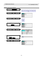
1. Operating the Setting and Display Unit.…………………………………………………
1.1 Setting Display Unit Appearance…………………………………………………..
1.2 Screen Configuration………………………………………………………………..
1.3 Menu List……………………………………………………………………………………..
1.3.1 Display the Menu Function Outline…………………………………………..
1.3.2 Moving the cursor………………………………………………………………
1.4 Operation Status…………………………………………………………………………….
1.5 Alarms / Warnings…………………………………………………………………………..
1.6 Operation Messages……………………………………………………………………….
1.7 Changing the screen……………………………………………………………………….
1.8 Changing the displayed part system……………………………………………………
1.9 Types of Menus……………………………………………………………………………..
1.10 Guidance Function………………………………………………………………………..
1.10.1 Parameter Guidance………………………………………………………….
1.10.2 alarm Guidance……………………………………………………………….
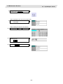
2. Monitor Screens…………………………………………………………………………………
2.1 Screen Configuration………………………………………………………………..
2.2 Operation Search…………………………………………………………………….
2.2.1 Executing an Operation Search………………………………………………
2.3 Restart Search……………………………………………………………………….
2.3.1 Main Screen…………………………………………………………………….
2.3.2 Executing Restart Search (Restart Type 1)………………………………….
2.3.3 Executing Restart Search (Restart Type 2)………………………………….
2.3.4 Returning to the Restart Position……………………………………………..
2.3.5 Executing the MSTB Commands……………………………………………..
2.4 Program Edit………………………………………………………………………….
2.5 Trace…………………………………………………………………………………..
2.5.1 Displaying the Machine Position Trace………………………………………
2.5.2 Canceling the Machine Position Trace……………………………………….
2.5.3 Displaying the Machine Position of the Tool Center Point Trace………….
2.5.4 Canceling the Machine Position of the Tool Center Point Trace………….
2.5.5 Changing the Display Range………………………………………………….
2.6 Program Check (2D)…………………………………………………………………
2.7 Program Check (3D) [700 series only]…………………………………………….
2.8 Counter All-axis Display…………………………………………………………….
2.9 Tool Compensation Amount………………………………………………………..
2.10 Workpiece Coordinate System Compensation………………………………….
2.11 Counter Set………………………………………………………………………….
2.12 Origin Set, Origin Cancel…………………………………………………………..
i
3
3
6
7
10
11
12
12
12
13
13
14
15
16
17
21
21
26
28
29
29
31
32
34
35
36
37
40
41
41
41
42
43
44
45
47
50
51
53
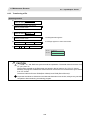
2.13 Manual Numerical Value Command (MST Code)………………………………
2.14 Modal Display……………………………………………………………………….
2.15 Program Tree Display……………………………………………………………...
2.16 Integrated Time Display……………………………………………………………
2.16.1 Setting the Integrated Time………………………………………………….
2.17 Common Variables…………………………………………………………………
2.17.1 Setting Common Variables…………………………………………………..
2.17.2 Copying/Pasting Common Variables……………………………………….
2.17.3 Erasing Common Variables………………………………………………….
2.18 Local Variables……………………………………………………………………..
2.18.1 Displaying the Arbitrary Local Variables……………………………………
2.19 Buffer Correction……………………………………………………………………
2.20 PLC Switch Function……………………………………………………………….
2.20.1 Turning PLC Switches ON/OFF……………………………………………..
2.21 Verify Stop…………………………………………………………………………..
55
57
60
61
63
64
66
67
68
69
71
72
74
75
76
3. Setup Screens…………………………………………………………………………...
3.1 Screen Configuration……………………………………………………………………….
3.2 Tool Compensation Amount……………………………………………………………...
3.2.1 Setting the Tool Compensation Data…………………………………………
3.2.2 Erasing the Tool Compensation Data………………………………………..
3.2.3 Copying/Pasting the Tool Compensation Data……………………………..
3.3 Tool Measurement………………………………………………………………………….
3.3.1 Carrying out tool length measurement……………………………………….
3.4 Tool Registration…………………………………………………………………………….
3.4.1 Registering a Tool in the Magazine Pot……………………………………...
3.4.2 Setting the PLC Command……………………………………………………
3.4.3 Setting/ Erasing the Tool No. of Spindle/ Standby Tools…………………..
3.5 Tool Life Management……………………………………………………………………..
3.5.1 Displaying the Group List……………………………………………………...
3.5.2 Displaying the Life Management Data in Group Units (M system)……..…
3.5.3 Displaying the Life Management Data
(L system: Tool life management I)…………………………………………..
3.5.4 Displaying the Tool Life Management Data in Group Units
(L system: Tool life Management II)………………………………………….
3.6 Workpiece Coordinate System Offset………………………………………………….
3.6.1 Setting the Coordinate System Offset………………………………………..
3.6.2 Erasing the Coordinate System Offset Amount……………………………..
3.6.3 Setting the Workpiece Coordinate Origin……………………………………
3.6.4 Changing the Coordinate System Display…………………………………..
3.7 Workpiece Measurement………………………………………………………………….
3.7.1 Carrying Out Surface Measurement…………………………………………
3.7.2 Carrying Out Hole Measurement……………………………………………..
83
83
85
91
92
93
94
97
98
ii
100
101
101
102
104
108
116
119
125
127
128
128
129
130
134
136
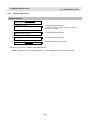
3.7.3 Carrying Out Width Measurement…………………………………………… 138
4. Edit Screens……………………………………………………………………………...
4.1 Screen Configuration……………………………………………………………………….
4.2 Program Editing……………………………………………………………………………..
4.2.1 Creating a New Machining Program………………………………………….
4.2.2 Editing a Machining Program………………………………………………….
4.2.3 Editing MDI Program…………………………………………………………...
4.2.4 Registering MDI Program in NC Memory……………………………………
4.2.5 Deleting a File…………………………………………………………………..
4.2.6 Editing Operations……………………………………………………………...
4.2.7 Changing the Display…………………………………………………………..
4.2.8 Displaying an Arbitrary Line…………………………………………………...
4.2.9 Rewriting Data…………………………………………………………………..
4.2.10 Inserting Data………………………………………………………………….
4.2.11 Deleting Data………………………………………………………………….
4.2.12 Searching for Character Strings……………………………………………..
4.2.13 Replacing Character Strings…………………………………………………
4.2.14 Copying/Pasting Data………………………………………………………...
4.2.15 Undoing Program Changes………………………………………………….
4.2.16 Correcting/Displaying Input Mistakes [700 series only]…………………..
4.3 Program Check (2D)……………………………………………………………………….
4.3.1 Checking Continuously………………………………………………………...
4.3.2 Checking One Block at a Time………………………………………………..
4.3.3 Canceling the Program Check………………………………………………..
4.3.4 Changing the Display Range………………………………………………….
4.3.5 Changing the Display Mode…………………………………………………..
4.3.6 Changing the Display Angle…………………………………………………..
4.4 Program Check (3D) [700 series only]…………………………………………………
4.4.1 Checking Continuously………………………………………………………..
4.4.2 Checking One Block at a Time………………………………………………..
4.4.3 Canceling the Program Check………………………………………………..
4.4.4 Enlarging and Reducing the Workpiece Shape……………………………..
4.4.5 Moving the Workpiece Shape…………………………………………………
4.4.6 Rotating the Workpiece Shape………………………………………………..
4.4.7 Performing an Interference Check……………………………………………
4.4.8 Setting the Workpiece shape………………………………………………….
4.4.9 Setting the Tool Shape………………………………………………………...
4.5 Program Input/Output………………………………………………………………………
4.5.1 Changing the Valid Area……………………………………………………….
4.5.2 Selecting a Device, Directory, and File………………………………………
4.5.3 Transferring a File………………………………………………………………
4.5.4 Comparing Files (Compare)…………………………………..……………...
iii
143
143
144
147
148
149
149
150
150
151
152
153
154
155
157
158
159
160
161
163
166
168
169
170
173
174
175
178
179
179
180
180
180
181
182
185
190
193
194
197
197
4.5.5 Erasing a File……………………………………………………………………
4.5.6 Changing a File Name (Rename)…………………………………………….
4.5.7 Creating a Directory……………………………………………………………
4.5.8 Merging a File…………………………………………………………………..
4.5.9 Formatting an External Device………………………………………………..
4.6 G Code Guidance…………………………………………………………………………..
4.7 Help Function………………………………………………………………………………..
4.7.1 Edit Help…………………………………………………………………………
4.7.2 NAVI MILL/ LATHE (Auto-simple programming function)………………….
197
197
197
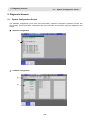
5. Diagnosis Screens………………………………………………………………………
5.1 System Configuration Screen…………………………………………………………….
5.2 Option Display Screen……………………………………………………………………..
5.3 I/F Diagnosis Screen……………………………………………………………..
5.3.1 Displaying the PLC Device Data……………………………………………...
5.3.2 Carrying Out Modal Output……………………………………………………
5.3.3 Carrying Out One-shot Output………………………………………………..
5.4 Drive Monitor Screen……………………………………………………………………….
5.4.1 Servo Axis Unit Display Items…………………………………………………
5.4.2 Spindle Unit Display Items…………………………………………………….
5.4.3 Display Items for the Power Supply Unit…………………………………….
5.4.4 Display Items for the Auxiliary Axis Unit [700 series only]…………………
5.4.5 Display Items for the Synchronous Error…………………………………….
5.4.6 Clearing the Alarm History…………………………………………………….
5.5 NC Memory Diagnosis Screen (NC Memory Diagn Screen)……………………
5.5.1 Writing/Reading the Data Using the NC Data Designation………………..
5.6 Alarm Screen………………………………………………………………………………...
209
209
211
212
213
214
215
6. Maintenance Screens…………………………………………………………………..
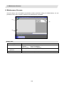
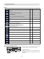
6.1 Parameter Screens…………………………………………………………………………
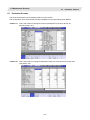
6.1.1 Changing the Parameter Display……………………………………………..
6.1.2 Setting the Parameters………………………………………………………...
6.1.3 Copying/Pasting Parameters………………………………………………….
6.1.4 How to Setup Machine Parameters……….………………………………….
6.2 Input/Output Screen………………………………………………………………………..
6.2.1 Changing the Valid Area……………………………………………………….
6.2.2 Selecting a Device, Directory and File……………………………………….
6.2.3 Transferring a File………………………………………………………………
6.2.4 Comparing Files (Compare)………………………………………………..…
6.2.5 Erasing a File……………………………………………………………………
6.2.6 Changing a File Name (Rename)…………………………………………….
6.2.7 Creating a Directory……………………………………………………………
6.2.8 Merging a File…………………………………………………………………..
229
231
iv
197
198
199
201
201
203
216
217
217
218
218
219
220
221
223
224
235
235
237
238
240
243
244
250
251
252
252
253
254
6.2.9 Formatting an External Device………………………………………………..
6.2.10 List of File Names…………………………………………………………….
6.2.11 Edit Lock B and C…………………………………………………………….
6.3 All Backup Screen…………………………………………………………………………..
6.3.1 Performing a Backup Operation………………………………………………
6.3.2 Performing a Restore Operation……………………………………………...
6.3.3 Backup of NC Parts information………………………………………………
v
255
255
256
257
258
260
261
Operating the Setting
and Display Unit
2
1. Operating the Setting and Display Unit
1.1
Setting Display Unit Appearance
1. Operating the Setting and Display Unit
This explains the functions common to the screens.
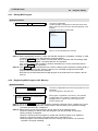
1.1
Setting Display Unit Appearance
An LCD display is used for the screen displays.
Operations such as screen transition and data setting are carried out with the NC keyboard.
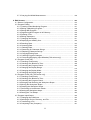
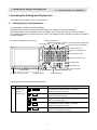
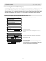
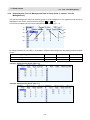
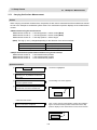
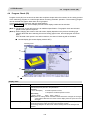
The setting display unit is configured of the LCD display, various keys and menu keys as shown below.
The drawing below shows a horizontal layout of the LCD display and NC keyboard, but these can also be
arranged vertically.
<Example for ABC layout keyboard unit>
(5) Data setting keys
(alphabet, numerals, symbols)
(3) Previous screen display key
(11) Frame keys
(1) Function keys
(Part system changeover)
(6) Particular keys
(8) Lower case input key
(16) Operation keys
(7) Data correction keys
(9) SHIFT key
(12) INPUT key
(14) Menu keys
(4) Menu changeover keys
(13) RESET key
(10) Cursor keys
(2) Page changeover key
(6) Particular keys
(15) Menu list key
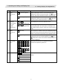
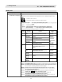
The following keys are provided on the keyboard.
Key type
(1)
Function key
Key
MONITOR
(MONITOR)
(Function
selection key)
Operation
This displays the screen related to "operations".
(Refer to "2. Monitor Screens".)
SET UP
(SETUP)
This displays the screen related to "setup".
(Refer to "3. Setup Screens".)
EDIT
(EDIT)
This displays the screen related to "editing".
(Refer to "4. Edit Screens".)
DIAGN
(DIAGN)
This displays the screen related to "diagnosis".
(Refer to "5. Diagnosis Screens".)
MAINTE
(MAINTE)
This displays the screen related to "maintenance".
(Refer to "6. Maintenance Screens".)
3
1. Operating the Setting and Display Unit
1.1
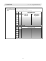
Key type
(2)
Page
Setting Display Unit Appearance
Key
Operation
Previous page key
PAGE
When the displayed contents cover several pages, this
" mark at
changeover
displays the contents of the previous page. The "
key
the top of the screen indicates that there is a previous page.
When the displayed contents cover several pages, this
Next page key
PAGE
displays the contents of the next page. The "
" mark at the
top of the screen indicates that there is a next page.
(3)
Previous
screen display
key (Part
system
This redisplays the previously displayed screen.
(BACK)
BACK
Previous screen display key
$
When using a multi-part system NC, this displays the data of
($→$)
$
Part system changeover key
changeover)
the next part system. The screen does not change if it is a
part system common screen or when only one part system is
used.
(4)
Menu
This changes the operation menu for the displayed screen to
(left side)
changeover
the current screen group screen selection menu. This is also
key
used to cancel the menu operations of the displayed screen.
When all of the menus cannot be displayed at once, this
(right side)
displays the menus not currently displayed. The "
"
" and
" marks at the bottom of the screen indicate that there are
menus not displayed.
(5)
(6)
Data setting
A
B
C
D
E
F
These keys are pressed to set alphabetic characters,
keys
G
H
I
J
K
L
numerals and operation symbols, etc.
M
N
O
P
Q
R
S
T
U
V
W
X
Y
Z
0
1
2
3
4
5
6
7
8
9
+
-
=
/
.
;
etc.
Particular keys
/
?
?
Help key
These key definitions differ according to the machine tool
builder.
SFP
F0
4
1. Operating the Setting and Display Unit
1.1
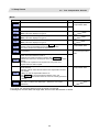
Key type
(7)
Data
correction
Setting Display Unit Appearance
Key
Operation
This inputs the data insertion mode. When a data setting key
(INSERT)
INSERT
is pressed, a character is inserted in front of the current
Data insert key
keys
cursor position.
The overwrite mode is entered when the DELETE,
C・B CAN, INPUT, cursor or TAB, etc., keys are pressed, or
when the screen is changed.
This deletes the character just before the cursor position in
(DELETE)
DELETE
the data setting area.
Data delete key
C•B
CAN
/
C•B
CAN
(C・B CAN)
This cancels the setting in the data setting area.
Cancel key
(8)
Lower case
ABC...
/abc...
(LOWER CASE)
input key
(9)
SHIFT key
(10)
Cursor keys
This changes the input between upper case and lower case
alphabetic characters.
SHIFT
(SHIFT)
This validates the setting on the lower line of data key.
This moves the cursor up or down one when setting data in
the screen display items.
This moves the cursor one item to the left or right when
selecting data in the screen display items.
at cursor left end: Moves to the right end of previous
line.
at cursor right end: Moves to left end of next line.
This moves the data input cursor one character to the left or
right in the data setting area.
(11)
Frame keys
(12)
INPUT key
This switches the tag.
INPUT
(INPUT)
This fixes the data in the data setting area, and writes it to
the internal data. The cursor moves to the next position.
(13)
RESET key
(14)
Menu keys
(15)
Menu list keys
RESET
(RESET)
This resets the NC.
This changes the screen and displays the data.
LIST
(MenuList)
This is function that displays each screen's menu
configuration as a list. (Refer to "1.7 Menu list")
(16)
Operation
keys
ALTER
(ALTER)
This is alternate key (Alt key).
CTRL
(CTRL)
This is control key.
(SP)
This is space key.
SP
5
1. Operating the Setting and Display Unit
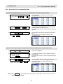
1.2
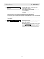
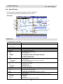
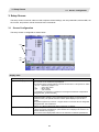
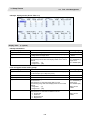
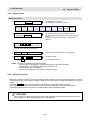
1.2
Screen Configuration
Screen Configuration
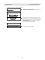
(1)
(2) (3)
(4)
(5)
(6)
(8)
(9)
(7)
(10)
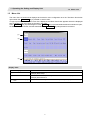
Display items
Display item
Details
(1) NC name
The currently displayed NC name (name set in parameter "#1135 unt_nm") is
displayed.
(2) Part system name
When using the multi-part system, the currently displayed part system name (name
set in parameter "#1169 system name") is displayed.
The part system name is not displayed for the 1-part system.
(3) Power ON request
This appears if a parameter requiring the power to be turned ON again has been
changed.
This flickers at an approx. one-second interval.
(4) Operation status
The displayed part system's operation mode is displayed.
(5) MDI status
The MDI status is displayed when the MDI operation mode is selected.
This does not appear when other operation modes are selected.
(6) Screen name
The tab for the currently selected screen is selected and displayed.
(7) Operation status
The NC operation status is displayed.
(8) Alarm
The currently occurring alarm or warning with the highest priority is displayed.
(9) Operation message
The operation message is displayed.
(10) Time
The current time is displayed. (Hour: minute)
6
1. Operating the Setting and Display Unit
1.3
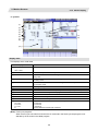
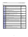
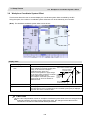
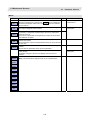
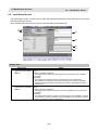
1.3
Menu List
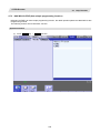
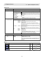
Menu List
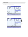
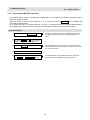
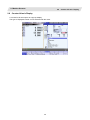
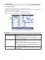
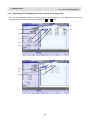
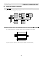
The menu list is a function that displays each screen's menu configuration as a list. The Menu list window
opens when the MenuList key is pressed on each screen.
If a pop-up window other than the menu list is displayed, the Menu list window appears above the displayed
pop-up window. The menu does not change in this case.
If the MenuList key is pressed again or if the Cancel key is pressed while the Menu list window is open,
the Menu list window closes, and the state before the MenuList key was pressed is recovered.
(1)
(2)
(3)
Display items
Display item
Details
(1) Screen name
The screen name is displayed.
(Example) Monitr/Setup
(2) Menu name
A list of the menu names (functions) included on each screen is displayed.
(Example) Search/Reserch
(3) Function outline display
area
An outline of the currently selected menu name (function) is displayed.
7
1. Operating the Setting and Display Unit
1.3
Menu List
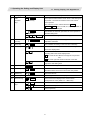
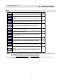
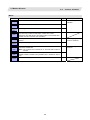
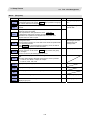
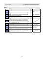
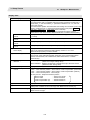
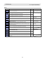
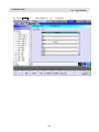
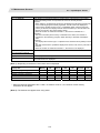
List of menu names (functions)
Screen
Monitr
Setup
Edit
Menu name
Outline
Search
Call a program for automatic operation.
Reserch
Restart machining from a selected block.
Edit
Edit the machining program searched for operation.
Trace
Trace the T path based on the machining program being executed.
Check
Trace the T path based on the machining program w/o running machine.
Cnt exp
Display counters of all axes & select the type of the counters.
Offset
Set & display tool offset data.
Coord
Set & display workpiece coordinate system offset.
Cnt set
Set the relative position counter to an arbitrary value.
MST
Set & display each command for S, M, T & 2nd M functions.
Modal
Display the execution modal value of the machining program.
Tree
Display program/MDI interrupt/user macro call in nesting structure.
Time
Set & display integrating time (date, time, power ON time, etc.).
Com var
Set & display the details of common variables.
Loc var
Specify a nesting level of subprogram & display local variables.
P corr
Correct & change the next command by block stop during auto-/MDI op.
PLC SW
Switch ON/OFF each NC ops. control signal allocated by ladder program.
G92 set
Perform origin set & origin cancel.
Col stp
Register arbitrary collation & stop position set as single block stop.
LD MTR
Spindle load and Z axis load, etc. can be displayed in meter.
Sp-stby
The spindle tool No. and the standby tool No. can be displayed.
T-ofs
Set & display tool offset data.
T-meas
Measure T length & radius manually & set them as tool offset amounts.
T-reg
Register T No. according to the magazine pot, spindle & wait position.
T-life
Scale workpiece to figure face/hole ctr/wid ctr & set as coord ofs.
Coord
Set & display workpiece coordinate system offset.
W-meas
Set & display user parameters.
User
Display & edit MDI programs set in NC memory.
MDI
Edit (add/delete/change) programs in NC memory & create new ones.
Cnt set
Set the relative position counter to an arbitrary value.
MST
Set & display each command for S, M, T & 2nd M functions.
T-list
Reference & display T-codelist.
Pallet
The machining program is registered into the pallet of APC.
Edit
Edit (add/delete/change) programs in NC memory & create new ones.
Check
Trace the T path based on the machining program w/o running machine.
NAVI
Create the part program simply.
I/O
Input/Output machining programs betw. NC memory & external I/O device.
8
1. Operating the Setting and Display Unit
1.3
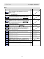
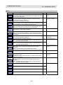
Screen
Diagn
Mainte
Menu name
Menu List
Outline
Config
Display the H/W & S/W
Option
Display the details of the options registered in NC memory.
(S/W No. & version) configurations.
I/F dia
Set & display input/output signals of the ladder program.
Drv mon
Display drive diagnostic information. (servo/spindle/power supply).
Mem dia
Set & display NC internal data.
Alarm
Display a list of currently occurring alarms & their messages.
Selfdia
Display the H/W & Operation stop state.
NC Smp
Set Sampling parameter & Sample NC internal data.
A net
Customer service is available by connecting NC with NC service.
Mainte
Perform NC memory format/abs. para. setting/maint. data backup, etc.
Param
Select a type of parameter to set & display the parameter values.
I/O
Input/Output machining programs betw. NC memory & external I/O device.
9
1. Operating the Setting and Display Unit
1.3
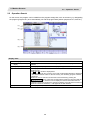
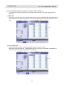
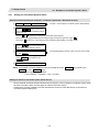
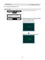
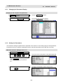
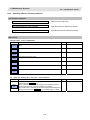
1.3.1
Menu List
Display the Menu Function Outline
Operation method
(1) Press the
MenuList
The Menu list window appears showing the selected
screen's menu list at the top.
key.
When the MenuList key is pressed while
editing the file on the Edit screen, a prompt
to confirm whether to save the program
appears before Menu list window opens.
(2) Using the ↑, ↓, →, ← and page keys, move
the cursor to the menu for which the function
outline is to be displayed.
The function outline for the selected menu appears.
The function outline does not appear if a menu with no
name is selected.
The cursor does not move to the group
name.
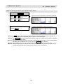
Directly Moving to the Menu Function with function key.
Operation method
(1) Press the
MenuList
The Menu list window appears showing the selected
screen's menu list at the top.
key.
(2) Using the ↑, ↓, →, ← and page keys, move
the cursor to the menu to move to.
The function outline for the selected menu appears.
(3) Press the
The selected menu function can be moved to directly.
The menu is not moved to if a menu with no name is
selected.
The Menu list window closes after moving.
INPUT
key.
10
1. Operating the Setting and Display Unit
1.3
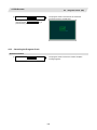
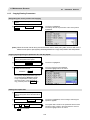
1.3.2
Menu List
Moving the cursor
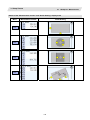
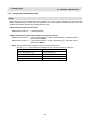
Operation method
(1) Press the
MenuList
The Menu list window appears showing the selected
screen's menu list at the top.
key.
(2) Press the ↓ ↑ ← →key four times.
(3) Press the
Page T
Page S
The cursor moves down four times, and the screen scrolls.
The screen scrolls.
key once.
(Note 1) The cursor moves in the same way even when the
|← key is pressed.
(Note 2) The cursor moves in the same way even when the
→|
11
key is pressed.
1. Operating the Setting and Display Unit
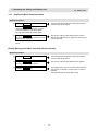
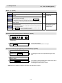
1.4
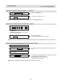
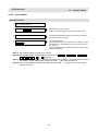
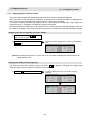
1.4
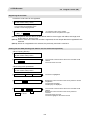
Operation Status
Operation Status
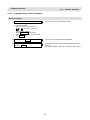
1
HLD
2
HLD
3
HLD
4
BST
The operation status displays the currently selected NC operation status for each part system. (The status for
up to four part systems is displayed.)
Symbol
EMG
1.5
Details
In emergency stop
Character color
Background color
Red
Dark gray
RST
Resetting NC
White
Dark gray
LSK
Paper tape reader is in label skip state
White
Dark gray
BST
In block stop
White
Dark gray
HLD
Operation halted
White
Dark gray
SYN
Synchronizing
White
Dark gray
AUT
In automatic operation
White
Dark gray
RDY
Operation completed state
Green
Dark gray
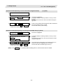
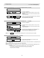
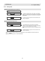
Alarms/Warnings
When an alarm or warning occurs, the alarm No. and alarm message character string are displayed.
(Example) Warning display
S51 Parameter error
1.6
Character color
Background color
Alarm
White
Red
Warning
Black
Yellow
Character color
Background color
Black
Green
Operation Messages
(Example)
Searching
Operation messages
The operation message can be reset by pressing any key.
12
1. Operating the Setting and Display Unit
1.7
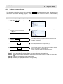
1.7
Changing the screen
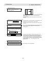
Changing the screen
When the function selection keys are pressed, the displayed screen changes to the screen corresponding to
the key. The displayed pop-up window closes.
If the function selection keys are pressed while editing the machining program or MDI program, a prompt to
confirm whether to save the program appears before changing to the screen corresponding to the key.
Displayed screen
MONITOR
SET UP
EDIGT
Monitor
DIAGN
MAINTE
Maintenance
Edit
Diagnosis
Setup
1.8
Changing the displayed part system
When the
$ $
BACK
keys are pressed, the displayed part system changes.
The displayed part system No. is counted up by one each time the
$ $
BACK
keys are pressed. If the displayed
part system No. exceeds the value number of part systems, the displayed part system No. returns to 1.
13
1. Operating the Setting and Display Unit
1.9
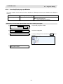
1.9
Types of Menus
Types of Menus
The menus are categorized into the following types according to the operation that takes place after the menu
key is pressed.
A : The menu is highlighted, and the system waits for the user input. After the input, the operation follows
the input details.
B : The menu is highlighted, and operation starts.
C : Operation starts without highlighting the menu.
In section "2. Monitor screen" and following, the types are described in the following method.
(Example) Explanation of menus used for editing the program on the Edit screen (excerpt)
Menu
Details
Type
String
search
When the character string is designated and the
pressed, that character string is searched for.
String
replace
If the character string to be searched for and the character string to
be replaced are separated with a "/" and designated, when the
INPUT key is pressed, the replace operation takes place.
Operation when menu is pressed
14
INPUT
key is
Reference
A
4.2.11 Searching for
character strings
A
4.2.12 Replacing
character strings
Menu type
Reference section
1. Operating the Setting and Display Unit
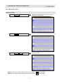
1.10
1.10
Guidance Function
Guidance Function
The parameter/operation guidance function displays the details of the parameters or the operation methods
according to the state of the screen currently being displayed.
Screen configuration
The parameter/operation guidance window is displayed with the following type of configuration.
The parameter
detail or operation
method is
displayed.
Operation method
If the ? key is pressed on any screen, the guidance window will open. If a pop-up window other than the
guidance window is open, the guidance window will open over the currently opened pop-up window. In this
case, the menu state does not change. If ? key or CANCEL key is pressed again when the guidance window
is open, the guidance window will close and the screen will return to the previous state in which the ? key was
pressed.
15
1. Operating the Setting and Display Unit
1.10
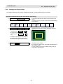
1.10.1
Guidance Function
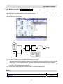
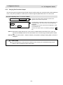
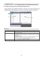
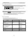
Parameter Guidance
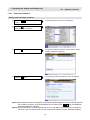
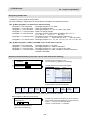
Displaying the parameter guidance
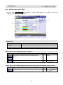
(1) Press the Param menu on maintenance
screen.
The machining parameter screen is displayed.
(2) Press the
key, and move the cursor
to "#8005 ZONE r" parameter.
(3) Press the ? key.
The guidance window is opened, and the detail of "#8005
ZONE r" parameter is displayed.
(4) Press the
The operation method for parameter screen is displayed.
key.
(Note 1) While guidance window is displayed, the parameter details displayed on each parameter type tab
are recorded. Therefore, when the parameter type is switched with
/
key, last displayed
parameter details are displayed.
(Note 2) If the parameter No. cannot be gotten (the cursor is non-display, the cursor is put on blank line,
the cursor is put on comment line), the top of parameter guidance for each parameter appears.
16
1. Operating the Setting and Display Unit
1.10
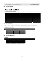
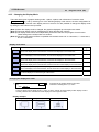
1.10.2
Guidance Function
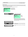
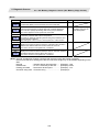
Alarm Guidance
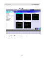
The alarm guidance is the function that displays message, details and remedy for the currently occurring
alarms.
This function is an option.
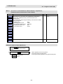
Screen configuration
The alarm guidance is displayed in "alarm" tag on "operation/parameter/alarm guidance window".
The "alarm" tag is on the rightmost end of the guidance window.
A scroll bar appears when details and remedy, etc. do not fit in one page.
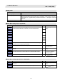
(1)
(2)
(3)
Display items
Display item
Details
(1) Message
This displays "NC alarm" and "PLC alarm message". The displayed content is same
as the content displayed in the alarm message of the diagnosis screen.
(2) Number of page
This displays "order of priority / total number of occurring alarms".
(3) Details/Remedy, etc.
This displays detail and remedy, etc. for alarm message.
17
1. Operating the Setting and Display Unit
1.10
Guidance Function
Operation method
If the ? key is pressed on any screen, the alarm guidance window will open. If a pop-up window other than the
alarm guidance window is open, the alarm guidance window will open over the currently opened pop-up
window. In this case, the menu state does not change. If ? key or CANCEL key is pressed again when the
guidance window is open, the guidance window will close and the screen will return to the previous state in
which the ? key was pressed.
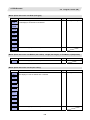
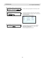
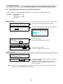
Displaying the alarm guidance
(1) Press the ? key during occurring alarm on
operation screen.
(Ex.) When "H/W stroke end axis exists"
and another alarm occur.
The guidance window is opened while "alarm" tag is valid.
The alarm details and remedy are displayed for "H/W stroke
end axis exists".
(Note 1) The alarm guidance is executed for the alarm that is occurred when the ? key has been pressed.
Therefore, the guidance will be displayed continually even if the alarm is reset while the alarm
guidance is displayed. The alarm guidance is not executed for the alarm that has occurred while
the alarm guidance is displayed.
(Note 2) If the ? key is pressed when an alarm is not occurring, the operation/parameter guidance
appears. In this state, if the "alarm" tag is selected with the right frame key, nothing is displayed in
the message, details and remedy columns. (These columns are blank.)
(Note 3) All the explanations of the alarm having the same error class and No. are displayed in the details
column.
18
Monitor Screens
20
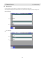
2. Monitor Screens
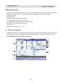
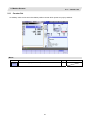
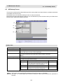
2.1
Screen Configuration
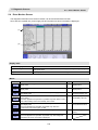
2. Monitor Screens
Various information related to operation, such as the axis counter, speed display and MSTB command are
displayed on the Monitor screen. The following operations regarding operation can be executed.
(1) Operation search
(2) Restart search
(3) Editing the searched machining program
(4) Trace (Display of machine movement path)
(5) Check (Display of NC program's tool movement path)
(6) Correction of operating program's buffer
(7) Counter set
(8) Manual numeric command
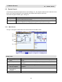
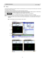
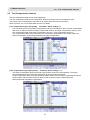
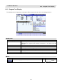
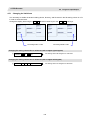
2.1
etc.
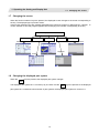
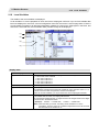
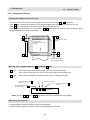
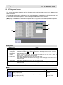
Screen Configuration
"Auto/MDI" and "Manual" are displayed at the upper left of the screen. These displays change according to
the mode selection switch. The details displayed for [Auto/MDI] differ according to the number of NC axes.
[For Auto/MDI (Part system with five or less axes)]
(6)
(7)
(8)
(1)
(9)
(10)
(11)
(2)
(12)
(3)
(4)
(5)
21
2. Monitor Screens
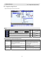
2.1
Screen Configuration
[For Auto/MDI (Part system with six or more axes)]
[For Manual]
(6)
(7)
(8)
(1)
(9)
(10)
(11)
(12)
(5)
22
2. Monitor Screens
2.1
Screen Configuration
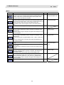
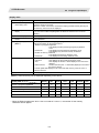
Display items
Display item
Details
(1) Counter display
This displays the counter of the relative position and workpiece coordinates positions,
etc.
If each axis is in a specific position or status, the following status symbol appears.
#1 to #4 : No. 1 to No. 4 reference position
][
: Servo OFF state
MR
: Mirror image
><
: Axis removed state
Whether to allow for the tool length compensation and tool radius compensation can
be set with the parameter "#1287 ext23/bit4".
(2) G modal simple display
This displays the modal status.
G command modal status of Group 1
G command modal status of Group 3
Selected workpiece coordinate system
Tool radius compensation modal, compensation No. shape compensation amount,
tool radius wear amount
Tool length compensation modal, compensation axis name, compensation No.,
shape compensation amount, tool length wear amount
(3) Cycle time display
This displays the automatic operation time and cycle time.
The displayed items are switched with integrated time window.
(4) Completed workpiece
display
This displays the number of workpieces which have been completed.
The display follows the machining parameters "#8001 WRK COUNT M" to "#8003
WRK COUNT LIMIT".
(5) Machine status animated
display
This displays the current tool No., tool type, next command movement direction,
coordinate rotation status, mirror image status, and spindle rotation direction/coolant
status.
Note that the spindle rotation direction/coolant status display differ according to the
machine tool builder.
(6) M, T, B commands
This displays the values command for M (miscellaneous function command value), T
(tool command value) and B (2nd miscellaneous function command value).
The presence of a 2nd miscellaneous function command value depends on
parameter "#1170 M2name".
Refer to "Manual numerical value command" for the manual numerical value
commands.
(7) Speed display
In interpolation feed:
This displays the vector direction speed currently being moved in.
In each axis independent feed:
This displays the speed of the axis with highest speed.
The actual machine feedrate is displayed with the parameters "#1125 real_f".
(8) S command,
spindle actual rotation
speed display
This displays the S (spindle command rotation speed) and spindle actual rotation
speed value.
If there are two or less spindles, the S command value and the spindle actual rotation
speed are displayed.
If there are three or more spindles, only the S command value is displayed.
(9) Spindle/Wait display
The spindle tool No. and the standby tool No. are displayed.
These displayed contents differ according to the machine tool builder.
(10) Load meter display
The spindle load and Z axis load, etc., are displayed in a bar graph.
If Spindle/standby display is not being used, a load meter can be displayed in the
Spindle/standby display area. These displayed contents differ according to the
machine tool builder.
23
2. Monitor Screens
2.1
Display item
Screen Configuration
Details
(11) Machining program
currently being executed
(Note)
Main
010…
This displays the program No., sequence No. and block No. currently being executed.
Sub
01234…
When a subprogram is being executed, this displays the subprogram's program No.,
sequence No. and block No.
(12) Buffer display
This displays the contents of the machining program currently being executed.
The block being executed is highlighted.
(Note) If the program No. (program name) exceeds 12 characters, "*" will appear at the 12th character.
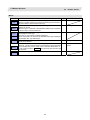
Menus
Menu
Details
Type
Reference
This executes operation search.
2.2 Operation Search
This executes restart search.
2.3 Restart Search
This edits the machining program in search.
2.4 Program Edit
This executes trace.
2.5 Trace
This checks the program.
This menu does not appear if the program check function option is not
provided.
2.6 Program Check (2D)
2.7 Program Check (3D)
This enlarges the counter, and displays the counters for all axes.
2.8 Counter All-axis
Display
This displays the tool compensation amount.
A value can also be set for the tool compensation amount.
2.9 Tool Offset Amount
This displays the workpiece coordinate system offset.
A value can also be set for the workpiece coordinate system offset.
2.10 Workpiece
Coordinate System
Offset
A arbitrary value can be set in the relative position counter.
2.11 Counter Set
This executes a manual numerical value command.
2.13 Manual Numerical
Value Command
24
2. Monitor Screens
2.1
Menu
Details
Screen Configuration
Type
Reference
This displays the program modal.
2.14 Modal Display
This displays the program tree.
2.15 Program Tree
Display
This displays the date, time and integrated time, etc., The date, time
and integrated time, etc., can also be set.
2.16 Integrated Time
Display
This displays the common variables.
A value can also be set for the common variable.
2.17 Common Variables
This displays the local variables.
2.18 Local Variables
This corrects the buffer.
2.19 Buffer Correction
This turns the PLC switches ON or OFF.
2.20 PLC Switch
Function
This sets and cancels the origin.
2.12 Origin Set, Origin
Cancel
This executes verify stop.
2.21 Verify Stop
The spindle load and Z axis load, etc., are displayed in a bar graph.
These displayed contents differ according to the machine tool builder.
2.22 Load Meter Display
The current spindle tool No. and the standby tool No. are displayed.
These displayed contents differ according to the machine tool builder.
2.23 Spindle, Standby
Display
25
2. Monitor Screens
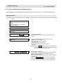
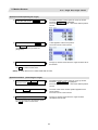
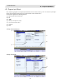
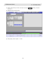
2.2
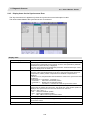
2.2
Operation Search
Operation Search
On this screen, the program can be called from the program storage site, such as a memory, by designating
the program (program No.) to be automatically run and the program start position (sequence No., block No.).
(1)
(2)
(3)
(4)
Display items
Display item
Details
(1) Device name, directory
display
This displays the device name and directory designated when the program was
selected.
(2) Capacity display
This displays the capacity of the device displayed in (1).
(3) List of directories and files This displays a list of the contents contained in the device or directory
displayed in (1).
Use ½ and ¾ to scroll the displayed list.
If the device is an HD, FLD, memory card or DS, the file update date/time is displayed
in the <Date/Comment> field. For the NC memory, the machining program comment
is displayed.
Whether to show or hide the comment field can be selected by pressing the
Comment nondisp menu. When the comment field is hidden, the file name field will
be enlarged. (Up to 13 characters can be displayed in the file name field when the
comment is shown, and 32 when the comment is hidden.) If the file name exceeds the
maximum number of characters, "*" will appear at the last character.
(4) Input area
This displays the input key details.
26
2. Monitor Screens
2.2
Operation Search
Menus
Menu
Details
Memory
Type
This selects the device for searching for the program.
When a device with directory is selected, the route is selected first.
C
Reference
2.2.1 Executing an
Operation Search
C
HD
NC
serial
C
Memory
card
C
C
DS
C
FLD
List
update
This updates the list contents. (The latest contents of the currently
selected device and directory are listed.)
C
Sort
change
This changes the method that the list is sorted.
C
2.2.3 Changing the
Sorting Method
This changes whether to show or hide the comment field in the list.
When the comment field is hidden, the file name field will be enlarged.
B
2.2.2 Changing Whether
to Show or Hide the
Comment Field
This closes the pop-up window and quits this function.
C
Comment
nondisp
Close
(Note 1) Some items may not be displayed depending on the device.
{: Displayed
Device
×: Not displayed.
Memory
HD
NC serial
Memory card
DS
FLD
Prog entry
{
{
×
{
{
{
Remain
{
×
×
×
×
×
Memory side
{
{
×
{
{
{
Remain
{
{
×
{
{
{
List
{
{
×
{
{
{
Display item
(Note 2) When using NC serial, the port number set with parameter "#9005 TAPE MODE PORT" is
connected, and search.
27
2. Monitor Screens
2.2
2.2.1
Operation Search
Executing an Operation Search
Operation method
(1) Select the part system to run with the
$<->$ keys.
The selected part system appears on the upper left of the
screen.
(2) Press the main menu
The sub-menu appears.
The list appears as a pop-up window.
Search .
(3) Select the device.
(Example) HD
The selected device name and route directory (HD:/) appear
in the Device name, Directory display field.
(4) Using the ↑, ↓, ½ and ¾ keys, move the
cursor to the directory containing the file to
be set.
The following is displayed.
If the list contents differ from the actual device or directory, press the menu
(5) Press the
INPUT
key.
List Update .
The active window changes to the directory.
(6) Using the ↑, ↓, ½ and ¾ keys, move the
cursor to the target machining program.
(7) Press the
INPUT
key.
The search starts.
When the search is completed, the message "Search
Complete" appears.
The searched device and program position appear in the
field for displaying the machining program currently being
executed.
The list closes, and the main menu appears again.
28
2. Monitor Screens
2.3
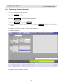
2.3
Restart Search
Restart Search
If machining is temporarily stopped due to tool breakage, etc., the program restart function searches for the
block of the machining program to be restarted, and restarts machining from that block.
There are two types of restart, type 1 and type 2.
Restart method
Details
Restart type 1
After machining is reset due to a tool breakage, etc., machining is restarted from the designated
sequence number and/or block number.
Restart type 2
After machining program is stopped due to a holiday, etc., and the power is turned OFF and ON,
machining is restarted from the designated sequence number and/or block number.
2.3.1
Main Screen
The type 1 and type 2 restart search can be executed from the Main screen.
(1)
(2)
(3)
(4)
(5)
(6)
Display items
Display item
Details
(1)
Device and directory
display
This displays the device and directory where the searched machining program is
located.
(2)
Research position
This displays the researched main program position (program No., sequence No.,
block No.).
(3)
Restart type
This displays the restart search type.
(4)
Position when restart
search is completed
This displays the position on the local coordinate system when the restart search is
completed.
(5)
Remaining distance when This displays the remaining distance when the restart search is completed.
restart search is
completed
(6)
Input area
This displays the input key details.
29
2. Monitor Screens
2.3
Restart Search
Menus
Menu
Details
Type
Reference
Search
exec
This starts the restart search based on the designated device,
directory, program number (O), sequence number (N), block number
(B) and number of block execution times (P).
C
This changes to the pop-up window for executing top search, and
enables top search.
When the type 1 is selected or the parameter "#8914 Auto Top search"
is set, this menu cannot be selected.
B
Top
search
This selects the restart search type. Restart search is executed with
the highlighted restart type.
The type 1 or type 2 menu is always highlighted.
When restart search is executed, the selected restart type is displayed
at the display item "(3) Restart type".
B
File set
This changes to the pop-up window for setting the file, and enables
the file to be selected.
B
2.3.3 File Setting Screen
B
MSTB
history
This opens the MSTB history screen as a pop-up window.
The M, S, T and B command used in the machining program are listed
on the MSTB history screen. If the cursor is moved to the listed M, S,
T or B command and the INPUT key is pressed, that command will
be executed.
2.3.4 MSTB History
Screen
This closes the pop-up window and quits this function.
C
Type1
Type2
Close
30
2.3.2 Top Search Screen
2. Monitor Screens
2.3
2.3.2
Restart Search
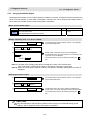
Executing Restart Search (Restart Type 1)
When feed hold has been applied and reset because the tool has broken, etc., restart with Restart type 1.
Operation method
(Example) When tool breakage during execution of O1000 N7 occurred, and restarting from the O1000 N6
block.
(1) Press the feed hold button and retreat to
the tool change position by manual means
or MDI.
Press the reset key and suspend the
present processing.
(2) Replace with a new tool.
(3) When using tape operation, index the top
of the tape.
(4) Press the main menu
Resrart .
The submenu appears.
The main screen for restart search appears as a pop-up
window.
(5) Set the position to restart search in the
setting area.
Delimit the ONB number in the setting area using /.
<When O No. was attached>
The main or sub program is targeted.
(Ex.) 1000/6/0
<When O No. was not attached>
The program currently searched is targeted.
(Ex.) /6/0
(Note) When the INPUT key is pressed without entering data
in the input area, restart search will be carried out for
the last execution block. (Type 1 only)
(6) Press the
menu.
Restart search is executed.
The message "In restart search" appears during the search
process, and the message "Restart search complete"
appears when completed.
Each axis' restart position and the restart remaining distance
are displayed.
When the MSTB history menu is pressed, the MSTB
history screen will open as a pop-up window, and the M, S, T,
B command used in the machining program will be listed.
INPUT
or
Search exec
31
2. Monitor Screens
2.3
2.3.3
Restart Search
Executing Restart Search (Restart Type 2)
If a machining program differing from the machining program to be restarted was run with tape, memory or HD
operation before starting restart search, restart the respective machining program with restart type 2.
The restart type 2 operation sequence is the same as restart type 1, but necessary matters for starting the
machining program, such as setting the coordinate system, must be completed before starting restart search.
When the parameter "#8914 Auto Top search" is "0", execute the top search for the machining program.
Operation method (When the parameter "#8914 Auto Top search" is "0")
(Example) When restarting from subprogram O123 N6 B2 called from main program O1000
(1) Turn the power ON, and return all axes to
the reference position.
(2) In the MDI mode, set the coordinate
system to be used when starting the
program to be restarted.
(3) Move each axis to the program restart
position.
(4) When using tape operation, index the top
of the tape.
(5) Press the main menu
Restart search .
The submenu appears.
The main screen for restart search appears as a pop-up
window.
(6) Press the Type 2.
(7) Press the sub-menu
Top search .
The window for top search appears as a pop-up window.
(8) Using the ↑ , ↓ , ½ and ¾ keys, move the
cursor to the target machining program.
Set the cursor to 1000.
(9) Press the
The top search starts.
When the top search is completed, the message "Search
Complete" appears.
The top search pop-up window closes, and the main screen
for restart search appears as a pop-up window.
INPUT
key.
The search can be executed by pressing
the menu Search exec instead of the
INPUT key.
32
2. Monitor Screens
2.3
(10) Set the position to restart search in the
setting area.
Restart Search
Delimit the ONBP number in the setting area using /.
<When O No. was attached>
The restart search is executed at designated position by
NBP No. with the set O No. at the head.
(Ex.) 123.PRG/6/2/1
<When O No. was not attached>
The program currently searched is targeted.
(Ex.) /6/2/1
P sets the number of times that the block targeted for the restart search appears.
For example, if a block in a subprogram is searched, and the subprogram is called out several times,
the block to be searched is also executed several times. Thus, which execution block to be searched
must be set. (If "0" is set, it is handled in the same manner as "1".)
To search the first execution block, or to search for a block executed only once, this item does not
need to be set.
(11) Press the
menu.
INPUT
or
Search exec
Restart search is executed.
The message "In restart search" appears during the search
process, and the message "Restart search complete"
appears when completed.
Each axis' restart position and the restart remaining distance
are displayed.
When the MSTB history menu is pressed, the MSTB
history screen will open as a pop-up window, and the M, S, T,
B command used in the machining program will be listed.
33
2. Monitor Screens
2.3
2.3.4
Restart Search
Returning to the Restart Position
The axis is returned to the restart position after restart search is completed.
The method for returning to the restart position (manual/automatic) can be selected with the parameters
"#1302 AutoRP".
0 : Manual restart position return
1 : Automatic restart position return
Operation method (manual restart position return)
(1) Turn the restart switch ON.
(2) Enter the manual (JOG/rapid traverse)
mode.
(3) Move the axis in the restart return
direction.
The restart position and "RP" appear sequentially from the
axes that have been returned. The Restart remaining
distance is "0".
(4) When all axes have been returned, turn
the restart switch OFF.
(Note 1) When the restart switch is ON, move the axis in the same direction as the restart direction. If
moved in the reverse direction, the operation error "M01 R-pnt direction illegal" occurs. If the tool
needs to be retracted once, such as if the tool is interfering with the workpiece, turn the restart
switch OFF and retract the axis manually.
(Note 2) After restart position return is completed, the axis cannot be moved if the restart switch is ON. If
the axis is moved, the operation error "M01 restart switch ON" occurs.
(Note 3) If even one axis has not completed return to the restart position at cycle start, the error "T01
Restart pos. return incomplete" occurs. Note that if the axis has been returned to the restart
position once and is not at the restart position during cycle start, the alarm does not occur.
(Note 4) If the axis to be returned to the restart position is a machine lock axis, the operation error "M01
program restart machine lock" occurs. Release the machine lock before returning to the restart
position.
(Note 5) If the restart switch is turned to ON after the axis is returned to the restart position with the restart
switch OFF, "PR" may not be displayed. Return to the restart position after the restart switch is
turned ON.
34
2. Monitor Screens
2.3
2.3.5
Restart Search
Executing the MSTB Commands
If the MSTB history menu is pressed after restart search is completed, the MSTB commands used for
machining program appear.
When the cursor is moved to the listed M, S, T, B commands and the INPUT key is pressed, that
command will be executed.
Up to 35 M commands, 3 commands each for S1 to S4, 3 T commands and 3 B commands are displayed. If
many MSTB commands are used for machining, the MSTB commands used at first will not appear.
Operation method
(1) Press the submenu
MSTB history .
The pop-up window changes to the MSTB history window.
The MSTB commands used for machining program are
listed.
(2) Using the ↑ , ↓ , → and ← keys, move the
cursor to the position of the data to set.
(3) Press the
INPUT
key.
The designated command is executed. A value, which has
been commanded once, is displayed in gray. The cursor will
move to the next item.
(4) Repeat steps (2) and (3).
(5) When completed with all settings, press
the Close or MSTB history menu.
The MSTB history pop-up window closes and the restart
search main window appears as a pop-up window.
35
2. Monitor Screens
2.4
2.4
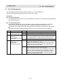
Program Edit
Program Edit
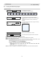
The machining programs are edited. When the main menu Edit is pressed, the operation searched
program (MDI program for MDI mode) appears.
If no program has been searched or tape operation has been executed, the edit window will not open.
When the program is edited, the key input data is directly written into the program display area. All data is
overwritten from the cursor position. "Editing" appears on the right side of the file name display when the input
starts. When the INPUT key is pressed, the program is saved in the NC memory and the "Editing"
message disappears.
Refer to "4.2 Program edit" for details.
36
2. Monitor Screens
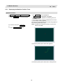
2.5
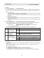
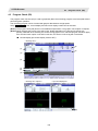
2.5
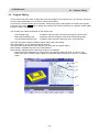
Trace
Trace
This function illustrates the actual machine's movement path or tool center point movement path, and draws
the actual machine movement.
This allows the machine operation to be monitored during machining.
The programs that can be traced are operation searched machining programs (MDI program for MDI mode).
If no program has been operation searched, the trace window will not open.
Using All display menu, normal display and whole display modes can be switched.
(Note 1) The trace function is an additional specification. The graphic trace option is required.
(Note 2) The tool center point trace function is an additional specifications. The 5-axis related options (tool
center point control, tool axis direction tool length compensation, tool handle feed & interrupt) are
required.
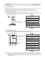
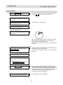
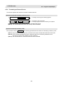
■ Normal display (full-screen display mode is OFF)
< Drawing area >
(1)
(2)
(3)
(4)
(5)
< Drawing area: 2-plane >
< Input area displayed >
(6)
37
2. Monitor Screens
2.5
Trace
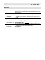
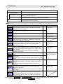
Display items
Display item
Details
(1) Counter
The counter of the axis targeted for the trace drawing is displayed. The three axes
which are displayed are set with the parameters.
[Trace]
The machine position is displayed.
[Tip trace]
The machine position of the tool center point is displayed.
(2) Display mode
The plane currently being drawn is displayed.
(3) Trace drawing area
This area is used to draw the tool path as graphics.
The zero point to be displayed can be switched between the machine position zero
point and workpiece coordinate position zero point with parameter "#1231 set03".
(4) Scale
The display range scale is displayed.
(5) Machining time display
The time required for machining is calculated and displayed. Nothing is displayed
during tracing.
(6) Input area
The input area appears when the menu Display range and
pressed.
The scale value and display mode are set.
The input area is hidden when the INPUT key is pressed.
(7) Buffer display
This displays the contents of the machining program currently being executed.
The block being executed is highlighted.
Display mode
Counter display conditions
Machine position trace mode
Tool center point trace mode
5-axis related specifications
disabled
Machine position
-
5-axis related specifications
enabled
Machine position
Machine position of tool center point
38
are
2. Monitor Screens
2.5
Trace
Menus
Menu
Details
Type
Reference
This activates the machine position trace mode. If any program is
currently running, the machine position path is traced from the current
position. If this menu is pressed during the machine position trace
mode, the trace mode will be turned OFF.
B
Trace
ON
2.5.1 Displaying the
Machine Position Trace
B
2.5.3 Displaying the Tool
Center Point Trace
Tip
traceON
This activates the tool center point trace mode. If any program is
currently running, the path of tool center point machine position path is
traced from the current position. If this menu is pressed during the tool
center point trace mode, the trace mode will be turned OFF.
Note that this menu does not appear if the 5-axis related option is
OFF.
This erases the data in graphic drawing area displayed on the screen.
C
C
Display
range
This changes the graphic drawing display range.
When this menu is pressed, the menu changes to the display range
change menu.
When the display range is changed, the graphic data displayed on the
screen is erased.
2.5.5 Changing the
Display Range
C
2.5.6 Changing the
Display Mode
Display
mode
This changes the drawing plane.
When this menu is pressed, the menu changes to the display mode
change menu.
There are three types of graphic display modes: 1-plane, 2-plane and
3D.
When the drawing plane is changed, the graphic data displayed on
the screen is erased.
All
display
This switches the normal display mode and the full-screen display
mode.
B
B
Program
display
This displays the machining program being executed on the graphic
drawing area.
This menu can be selected only when the full-screen display mode is
applied.
2.5.8 Switching the
Full-screen Display
Mode
C
Rotate
This sets the viewpoint angle for the 3D display mode.
When the viewpoint angle is changed, the graphic data displayed on
the screen is erased.
Note that this menu can be used only in the 3D display mode.
C
Std
range
The display range (scale and display position) is automatically set
from the machine movable area. The machine movable area is set
with the parameters "#2013 OT-" and "2014 OT+" (software limit).
When the display range is changed, the graphic data displayed on the
screen is erased.
This closes the pop-up window and quits this function.
C
Erase
Close
39
2.5.7 Changing the
Display Angle
2. Monitor Screens
2.5
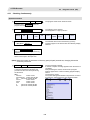
2.5.1
Trace
Displaying the Machine Position Trace
Operation method
(1) Press the
(2) Press
MONITOR
SEARCH
key
for machining program
• The
If
Trace ON
Tip TraceON
menu is highlighted.
is highlighted, unhighlight it.
• The machine position appears in the drawing area as a
tool mark.
• The machine position counter is displayed at the counter.
• The message "Tracing" appears.
(3) Press the main menu
(4) Press
CYCLE START
Trace ON .
After this, the machine position path is drawn with graphics in
the machine position trace mode.
(Note) If graphic check (2D) is executed, the "Trace ON"
status is cancelled.
button.
The machine position path is drawn with graphics.
The machine position path is drawn with a solid green line.
40
2. Monitor Screens
2.5
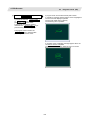
2.5.2
Trace
Canceling the Machine Position Trace
Operation method
(1) Start tracing with the machine position.
(2) Press the main menu
2.5.3
Trace ON .
• The Trace ON menu is unhighlighted.
• The tool mark in the drawing area is erased.
• The message "Tracing" is erased.
Displaying the Tool Center Point Trace
Operation method
(1) Press the main menu
Tip TraceON .
• The
Tip TraceON menu is highlighted.
If Trace ON is highlighted, unhighlight it.
• The tool center point appears in the drawing area as a tool
mark.
• The tool center position is displayed at the counter.
• The message "Tracing Tip Position" appears.
After this, the tool center point path is drawn with graphics in
the tool center point trace mode.
(Note) If graphic check (2D) is executed, the "Tip Trace ON"
status is cancelled.
2.5.4
Canceling the Tool Center Point Trace
Operation method
(1) Start tracing with the tool center point.
(2) Press the main menu
Tip TraceON .
• The Tip TraceON menu is unhighlighted.
• The tool mark in the drawing area is erased.
• The message "Tracing Tip Position" is erased.
41
2. Monitor Screens
2.5
2.5.5
Trace
Changing the Display Range
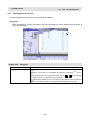
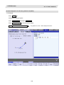
The graphic drawing's scale can be enlarged or reduced, and the position moved or centered.
Operation method (Enlarging the and reducing the drawing)
(1) Press the
Zoom
in
Display range
Zoom
out
(2) Press the menu
Up
Zoom in
A white frame indicating the display range appears on the
screen.
The display range input mode is activated, and the following
menu appears.
key.
Down
or Zoom out.
Left
Right
Centering
The size of the white frame changes according to the key
operations.
To enlarge the figure:
Press the menu Zoom In or the key.
To reduce the figure:
Press the menu Zoom out or the +
key.
A solid-line frame appears with respect to
the original scale when enlarging, and a
dotted-line frame appears when reducing.
(3) Press the
INPUT
key.
The display scale is changed.
By changing the display scale, the graphic data displayed on
the screen is erased.
It is also possible to change the display scale by setting a
scale value in the input area.
(Note) The changed scale value is held even after the power is turned OFF and ON.
42
2. Monitor Screens
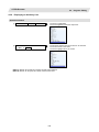
2.6
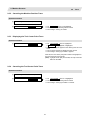
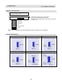
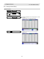
2.6
Program Check (2D)
Program Check (2D)
Program check (2D) is a function that draws the machining program movement path without executing
automatic operation. The machining program can be checked with graphic data drawn at a high speed.
The programs that can be checked are operation searched machining programs (MDI program for MDI
mode).
If no machining program has been operation searched, the program check window will not be opened.
Refer to "4.3 Program Check (2D)" for details.
(Note) The program check (2D) function is an additional specification. The graphic check option is required.
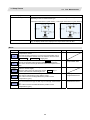
■ Normal display (full-screen display mode is OFF)
<Drawing area>
■ Full-screen display (full-screen display mode is ON)
<Drawing area >
43
2. Monitor Screens
2.7
2.7
Program Check (3D)
Program Check (3D)
Program check (3D) is a function that draws the workpiece shape and tool movement in the cutting process of
the machining program as a solid image without executing automatic operation. The machining program can
be checked with graphic data drawn at a high speed.
The operation searched machining program (MDI program for MDI mode) can be checked.
The Program Check window will not open if no machining program has been searched.
The workpiece shape and tool shape used with this function can be set on the Edit screen.
Refer to section "4.4 Program Check (3D)" for details.
(Note) The program check (3D) function is an additional specification. The graphic check and 3D solid
graphic check options are required.
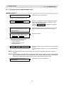
■ Normal display (full-screen display mode is OFF)
<Drawing area>
■ Full-screen display (full-screen display mode is ON)
<Drawing area>
44
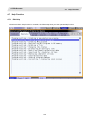
2. Monitor Screens
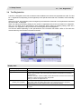
2.8
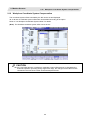
2.8
Counter All-axis Display
A counter for all axes opens as a pop-up display.
The type of displayed counter can be selected with the menu.
45
Counter All-axis Display
2. Monitor Screens
2.8
Counter All-axis Display
Menus
Menu
Details
Type
This displays the currently executed position
B
Work
co posn
This displays the G54 to G59 workpiece coordinate system modal No.
and the workpiece coordinate position in that workpiece coordinate
system.
B
Machine
posn
This displays the coordinate position of each axis in the basic machine
coordinate system having a characteristic position, specified by the
machine, as a zero point.
B
Remain
command
This displays the remaining distance of the movement command
being executed during automatic start or automatic halt. (The
remaining distance is the incremental distance from the current
position to the end point of that block.)
B
Next
command
This displays the details of the command in the block executed after
the block currently being executed.
B
Manual
int amt
This displays the amount moved with the manual mode while the
manual absolute switch was OFF.
B
Program
posn
This displays the value obtained by subtracting the tool compensation
amount compensated for that axis from the position actually being
executed for each axis.
B
This closes the pop-up window and quits this function.
C
This displays the position of the tool end from the workpiece
coordinate reference point in the selected workpiece coordinate
system.
B
This displays the position of the tool end from the machine coordinate
system reference point in the machine coordinate system.
B
This displays the amount moved in the selected axis direction using
the manual pulse generator in the hypothetical machine coordinate
system.
Basically this is updated only when manual ABS is OFF. If "#7905
NO_ABS" is set to "1", this will be updated regardless of the manual
ABS ON/OFF.
B
Relat
posn
Close
Tip wk
posn
Tip
machine
Pulse
(Note 1) The type of counter displayed first when the pop-up display appears is the relative position. If the
5-axis related option is ON, the counter will be the "Tip wk posn".
The counter which appears next is the type selected previously.
(Note 2) The menus Tip wk posn, Tip machine and Tip axis movement appear when the 5-axis related
option is ON.
46
2. Monitor Screens
2.9
2.9
Tool Compensation Amount
Tool Compensation Amount
The tool compensation data can be set and displayed.
The tool compensation data screen configuration differs according to the tool compensation type.
The number of tool compensation sets to be set or shown differs according to the option.
Refer to section "3.2 Tool Compensation Amount" for details.
[Tool compensation type I (M system)]
Parameter "#1037 cmdtyp" = 1
The combined amount of the shape compensation and wear compensation are set as the compensation
data, with no distinction between shape compensation memory and wear compensation memory. (The
tool compensation data is the shape compensation amount + wear compensation amount.)
The compensation data is used commonly for the tool length compensation, tool position offset, tool
radius compensation, and three-dimensional tool radius compensation.
[Tool compensation type II (M system)]
Parameter "#1037 cmdtyp" = 2
The shape compensation amount and wear compensation amount are set separately. The shape
compensation amount is furthermore divided into length and radius dimensions.
Of the compensation data, the length dimension data is used for the tool length compensation and tool
position offset, and the radius dimension data is used for the tool radius compensation and
three-dimensional tool radius compensation.
47
2. Monitor Screens
2.9
[Tool compensation type III (L system)]
Tool Compensation Amount
Parameter "#1037 cmdtyp" = 3
The wear data, tool length data and tool nose data are set separately. These are changed with the
sub-menu.
(a) Wear data
Set the tool nose wear amount for each tool used. When the tool compensation No. is designated by the
tool command (T command), compensation is carried out matching the tool length data and tool nose
data.
(b) Tool length data
Set the tool length in respect to the program basic position of each tool used.
When the tool compensation No. is designated by the tool command (T command), compensation is
carried out matching the wear data and the tool nose data.
48
2. Monitor Screens
2.9
Tool Compensation Amount
(c) Tool nose data
Set the tool nose radius value (tool nose R), wear radius value (R wear) and tool nose point (tool nose
point P) of the tool nose mounted on the tool for each tool used. When the tool offset No. is designated by
the tool command (T command), offset is carried out matching the tool length data and tool nose data.
CAUTION
If the tool offset amount or workpiece coordinate system offset amount is changed during
automatic operation (including during single block stop), the changes will be valid from the
command in the next block or after several subsequent blocks.
49
2. Monitor Screens
2.10
2.10
Workpiece Coordinate System Compensation
Workpiece Coordinate System Compensation
The coordinate system offset controlled by the NC can be set and displayed.
48 or 96 sets of coordinate system offset sets can be added according to the option.
Refer to "3.6 Workpiece Coordinate System Offset" for details.
(Note) The G92/G52 coordinate system offset cannot be set.
CAUTION
If the tool offset amount or workpiece coordinate system offset amount is changed during
automatic operation (including during single block stop), the changes will be valid from the
command in the next block or after several subsequent blocks.
50
2. Monitor Screens
2.11
2.11
Counter Set
Counter Set
An arbitrary value can be set in the relative position counter which opens as a pop-up window.
Menus
Menu
Close
Details
Type
This closes the pop-up window and quits this function.
51
C
Reference
2. Monitor Screens
2.11
Counter Set
Operation method
(1) Press the main menu
Counter set .
Instead of the operation above, the axis
name address key can be pressed to set
the counter.
(Example)
The relative position counter opens as a pop-up window.
The cursor appears at the No. 1 axis of the relative position
counter.
The relative position counter opens as a pop-up window.
The cursor appears at the designated axis (Z axis).
Z
(2) Input a numeric value.
(Example) 100.000
INPUT
The set value "100.000" appears at the cursor position. The
cursor moves to the next axis.
If the INPUT key is pressed without
inputting a value, zero (0) will be set.
(3) Repeat step (2) for each axis.
For axes that are not to be operated, press
the ↓ key and move the cursor.
The pop-up window closes when the counter has been set
for the last axis.
52
2. Monitor Screens
2.12
2.12
Origin Set, Origin Cancel
Origin Set, Origin Cancel
Origin set and origin cancel can be executed.
Menus
Menu
Details
Type
Origin
set
Origin
cancel
The origin is canceled.
The origin cancel mode is activated when this menu is pressed.
A
This closes the pop-up window and quits this function.
C
Close
Reference
A
The origin is set.
When main menu G92 set is pressed, the menu
highlighted and the origin set mode is activated.
Origin set
is
Differences between origin set and origin cancel
Function
Changes in the
counter value
Origin set
Origin cancel
The coordinate system is shifted so the current
position becomes the designated position of the
workpiece coordinate system.
This is equivalent to "G92 X0". (When X is the
target axis.)
The coordinate system is shifted so the zero
point of the workpiece coordinate system
matches the zero point of the basic machine
coordinate system.
This is equivalent to "G92 G53 X0". (When X is
the target axis.)
The relative position counter and workpiece
coordinate counters become "0".
The relative position counter matches the
machine coordinate counter.
The G92 shift amount is updated.
The G92 shift amount and the G52 shift amount
for the G54 to G59 coordinate system becomes
"0".
Offset
53
2. Monitor Screens
2.12
Origin Set, Origin Cancel
Operation method (Setting the origin)
(1) Press the main menu
The relative position counter opens as a pop-up window.
The menu Origin set is highlighted.
The cursor appears at the No. 1 axis of the relative position
counter.
G92 set .
(2) Input 0, and then press the
INPUT
key.
If the INPUT key is pressed without
inputting a value, zero (0) will be set.
(Origin zero)
(3) Repeat step (2) for each axis.
"0.000" appears at the cursor position.
The cursor moves to the next axis.
The pop-up window closes when the origin has been set for
the last axis.
For axes that are not to be operated, press
the ↓ key and move the cursor.
(Note) An error will occur if a value other than 0 is set.
Operation method (Canceling the origin)
(1) Press the main menu G92 set , and then
press the menu Origin cancel .
The relative position counter opens as a pop-up window.
The menu Origin cancel is highlighted.
The cursor appears at the No. 1 axis of the relative position
counter.
(2) Press the
The same value as the machine position appears at the
cursor position.
The cursor moves to the next axis.
INPUT
key.
(3) Repeat step (2) for each axis.
The pop-up window closes when the origin has been
canceled for the last axis.
For axes that are not to be operated, press
the ↓ key and move the cursor.
54
2. Monitor Screens
2.13
2.13
Manual Numerical Value Command
Manual Numerical Value Command (MST Code)
The spindle function (S), miscellaneous function (M), tool function (T) and 2nd miscellaneous function (B)
commands can be executed.
The manual numerical value command can be executed by inputting an address such as S, M, T or B, as well.
Menus
Menu
Close
Details
Type
This closes the pop-up window and quits this function.
Reference
C
Operation method (Executing T31 with a manual numerical value command)
(1) Press the main menu
MST .
The S, M, T, B display opens as a pop-up window.
S
M
T
B
The manual numerical value command
can also be issued by using the address
keys instead of the operation above.
(Example) T
100
50
4
1000
The S, M, T, B display opens as a pop-up window.
The cursor appears at T.
S
M
T
B
100
50
4
1000
(2) Using the ↑ and ↓ keys, move the
cursor to the position to be set.
The cursor moves.
(3) Input a value.
The input value is set.
31
INPUT
55
2. Monitor Screens
2.13
Manual Numerical Value Command
Operation method (Canceling the manual numerical value command)
The manual numerical value command mode is canceled by carrying out one of the following operations
before pressing the INPUT key.
• Press the menu Close
• Press the
key
• Change the screen
Setting/output range of manual numerical value command
The manual numerical value command setting range is shown below.
S
M
T
B
•
•
BCD
0 to 99999999
Signed binary
-99999999 to 99999999
-
0 to 99999999
0 to 99999999
-
Add a "-" sign before the value to set a negative value. The display will be a positive value.
A value larger than "#3001 slimt1" to "#3004 slimt4" or "#3005 smax1" to "#3008 smax4"cannot be
output for S.
56
2. Monitor Screens
2.14
2.14
Modal Display
Modal Display
The state of each modal during automatic operation is displayed.
The displayed details differ for the M system and L system.
<M system>
(1)
(3)
(2)
(4)
(6)
(7)
(5)
(8)
(9)
(10)
(11)
Display items
This displays each modal state.
Display item
(1) G00…G94
:
G69…G42.1
(2) G50:P=0.000000
(3) G54.1:P0
(4) G69:R=0.000
(5) G05:P0
Q1
Q2
P10000S
P10000
P1
P2
(6) G40:
D0
= 100.000000:
10.000000
(7) G49:
Z
H0
= 0.000000:
0.000000
(8) G07.1:OFF
(9) G08:
P0
P1
(10) FA
FM
(11)
S1 to S4
M1 to M4
T1 to T2
B
Details
Status of currently executed G command modal
Scaling magnification
Extended workpiece coordinate system
Coordinate rotation angle (Displays within a ±360° range)
High-speed machining mode
High-speed high-accuracy control 1
Spline interpolation
High-speed high-accuracy control 2 (SSS control ON)
High-speed high-accuracy control 2 (SSS control OFF)
High-speed machining mode I
High-speed machining mode II
Tool radius compensation modal
Compensation No.
Shape compensation amount in respect to tool radius
Tool radius wear amount
Tool length compensation modal
Compensation axis name
Compensation No.
Compensation amount
Tool length wear amount
Cylindrical interpolation modal
High-accuracy control mode
High-accuracy control mode OFF
High-accuracy control mode ON
F modal value of currently executed program command
Manual federate
Program command modal value of each currently executed command
S command
M command
T command
2nd miscellaneous function (B) command
57
2. Monitor Screens
2.14
Modal Display
<L system>
(1)
(9)
(2)
(3)
(4)
(5)
(6)
(10)
(11)
(12)
(7)
(8)
(13)
Display items
This displays each modal state.
Display item
Details
(1) G01…G94
:
G69…G42.1
Status of currently executed G command modal
(2) G54.1:P10
Extended workpiece coordinate system
(3) TX :
-12.345
The total value of the first axis' tool length and wear compensation amount for the tool
being used
(4) TZ :
12.345
The total value of the second axis' tool length and wear compensation amount for the
tool being used
(5) TY :
10.000
The total value of the additional axis' tool length and wear compensation amount for
the tool being used
(6) TG :
123
Tool length compensation No.
(7) TW :
123
Wear compensation No.
(8) V
12345678
Modal value for constant surface speed spindle rotation speed (V1 to V4)
(9) FA
24000.00
F modal value of currently executed program command
(10) FM
1200.00
(11) FS
0.0000
Program command synchronous feedrate modal value
(12) FE
0.0000
Thread lead command synchronous feedrate modal value
(13)
S1 to S4
M1 to M4
T1 to T2
B
Manual federate
Program command modal value of each currently executed command
S command
M command
T command
2nd miscellaneous function (B) command
(Note) Fixed cycle programs
When a fixed cycle command is executed, the G command in the fixed cycle subprogram is not
affected by the G modal in the called program.
58
2. Monitor Screens
2.14
Modal Display
Menus
Menu
Close
Details
Type
This closes the pop-up window and quits this function.
(Note) The menu is common for the M system and L system.
59
C
Reference
2. Monitor Screens
2.15
2.15
Program Tree Display
Program Tree Display
This displays the main program, subprogram, MDI interrupt and user macro call nesting structure.
Display items
Display item
Details
(1) 0
Program No. (0 to 15 characters)
If the program No. (program name) exceeds 15 characters, "*" will appear at the 15th
character.
(2) N
Sequence No. (0 to 99999)
(3) B
Block No. (0 to 99999)
(4) L
Remaining number of subprogram repetitions (0 to 99)
(5) Mode
Operation mode (0 to 7 characters)
(6) Main
Main program
(7) 1 to 8
Called subprogram, user macro call and MDI interrupt
Menus
Menu
Close
Details
Type
This closes the pop-up window and quits this function.
60
C
Reference
2. Monitor Screens
2.16
2.16
Integrated Time Display
Integrated Time Display
The integrated time (date, time, power ON time, automatic operation time, automatic start time, external
integrated time 1, external integrated time 2, cycle time) controlled by the NC can be set and displayed.
Note that the cycle time cannot be set. (Cycle time is display only.)
The integrated times displayed in cycle time display area on "Auto/MDI" tag can be set.
Display items
Display item
Details
(1) #1 Date
The current date set in the NC is displayed.
Year: 4 digits, Month: 2 digit, Date: 2 digit (YYYY.MM.DD)
(2)
2 Time
The current time set in the NC is displayed with the 24-hour system.
(HH:MM:SS)
(3)
3 Power ON
This displays the total integrated time of the time from NC power ON to
OFF.(HH:MM:SS)
(4)
4 Auto oper
This displays the total integrated time of the work time from automatic start button
pressing in the memory (tape) mode to M02/M30 or reset button pressing
(HH:MM:SS)
(5)
5 Auto strt
This displays the total integrated time during automatic starting from automatic start
button pressing in the memory (tape) mode or MDI to feed hold stop, block stop, or
reset button pressing. (HH:MM:SS)
(6)
6 Ext time1
This content differs depending on machine tool builder specification.
(7)
7 Ext time2
This content differs depending on machine tool builder specification.
(8)
8 Cycle time
This displays the time that automatic operation is started from when the automatic
start button is pressed in the memory (tape) mode or MDI to when feed hold stop or
block stop is applied or the reset button is pressed.
61
2. Monitor Screens
2.16
Integrated Time Display
Menus
Menu
Details
Type
Reference
Time
setting
This sets the integrated time.
A
2.16.1 Setting the
Integrated Time
Time
select1
The time that is displayed in upper line on cycle time display
area is selected.
C
2.16.2 Setting the Time
Display Selection
Time
select2
The time that is displayed in bottom line on cycle time display
area is selected.
C
This closes the pop-up window and quits this function
C
Close
62
2. Monitor Screens
2.16
2.16.1
Integrated Time Display
Setting the Integrated Time
Operation method
(1) Press the menu
Time setting .
The time setting mode is entered.
The cursor appears at the "#1 Date" position in the
integrated time display.
(2) Input today's date.
(Example)
2003/8/19
"2003.08.19" appears at "#1 Date", and the cursor moves to
"#2 Time".
INPUT
(3) Set the data for each item, and press the
INPUT key.
When "#7 External integrated time 2" has been set, the
cursor disappears, and the time setting menu highlight is
turned OFF.
If the item does not need to be set, press
the ↓ key and move the cursor.
Note that #8 Cycle time cannot be set, so
the cursor will not move.
(Note 1) The data delimiters are as shown below.
Item
#1 Date
#2 Time to #7 Ext time2
#8 Cycle time
Valid delimiters during setting
" . " or " / "
Delimiters in display
"."
" : " or " / "
":"
":"
(Note 2) If the Time setting menu or
setting mode will be canceled.
key is pressed again during the time setting mode, the time
Setting range
Display item
#1 Date
2 Time
3 Power ON
4 Auto oper
5 Auto strt
6 Ext time 1
7 Ext time 2
Range
1980.1.1 to 2069.12.31
00:00:00 to 23:59:59
00:00:00 to 59999:59:59
63
2. Monitor Screens
2.17
2.17
Common Variables
Common Variables
The details of the common variables can be set and displayed on this screen.
If there is a common variable command (Note) in the machining program, the variable value (variable name)
set when the block is executed is displayed.
The number of common variable sets differs according to the specifications.
(Note) The variable names can be set for common variables #500 to #519.
(1)
(2)
(3)
Display items
Display item
Details
(1) Variable No.
This is the common variable No. There are address #100 and address #500
variables.
The #100 variables appear at the head when the power is turned ON.
If "#1052 MemVal" is set to "1" (Designate No. of common variable for common part
system), "*" is attached to the part system common variable. (Note that if there is only
one part system, "*" will not appear.)
(2) Variable value
The setting range is -999,999,999 to 999,999,999 or blank.
An exponential is displayed when a 7 digits are set in the integer section and 5 digits
or more as set in the decimal section.
(Example) 1234567 → 1.2346E+006, 0.00001 → 1.0000E-005
The minimum setting unit that can be set is 1.0000E-099 (99 digits below decimal
point).
(Note) When the setting is "blank", the setting will be handled as "0" in the
calculations. However, when the conditional expressions EQ or NE are used,
the blank will not be handled as "0".
(3) Variable name
A variable name can be assigned for #500 to #519.
Up to seven alphanumeric characters, starting with an alphabet character, can be set
for the variable name.
64
2. Monitor Screens
2.17
Common Variables
Menus
Menu
Type
Reference
This executes an absolute input.
C
2.17.1 Setting Common
Variables
This executes an addition input.
C
This designates the variable No. to be displayed at the head.
A
C
Undo
This returns the last rewritten data to its original value.
This menu key is valid for "Data Input", "Paste" and "Undo"
operations. Note that return to the original value is not possible after
variable clear and comment clear operations.
Copy
This copies the variable value and variable name at the cursor
position.
A
This pastes the copied variable value and variable name.
C
Variabl
clear
This clears the contents of the variable No. at the cursor position or
continuous variable Nos.
(Note) The contents are not cleared to "0". The state with no data is
entered.
A
Name
clear
This clears the variable No. at the cursor position or the continuous
variable number's variable name (Variable name: variable No. 500 to
519).
A
This closes the pop-up window and quits this function.
C
=Input
+Input
Variabl
No.
Paste
Close
Details
65
2.17.2 Copying/Pasting
Common Variables
2.17.3 Erasing Common
Variables
2. Monitor Screens
2.17
2.17.1
Common Variables
Setting Common Variables
Operation method (Setting "135.000" in variable No. 102)
(1) Press the menu
Variabl No .
(2) Designate the variable No.
The menu is highlighted.
The common variable for the set No. appears at the head.
102 INPUT
The cursor can be moved to 102 using the
↑ , ↓ ,
and
keys.
(3) Input a value.
The set value appears.
135 INPUT
The value can also be set by pressing the
menu =INPUT instead of the INPUT
key.
The value can also be input as an
exponential.
(1.35E2 INPUT or 1.35E2 =INPUT .)
Operation method (Adding "1.234" to variable No. 102)
(1) Select common variable 102 with the
same procedure as steps (1) and (2)
above.
(2) Input a value.
1.234 +INPUT
The value obtained by adding the input value to the original
value appears.
(Example) If the original value is 135.000, 136.234
appears. (135.000 + 1.234 = 136.234)
Operation method (Setting "COUNTER" as the variable name for variable No. 509)
(1) Select common variable 509 with the
same procedure as steps (1) and (2)
above.
The cursor appears at the cursor 509 variable position.
(2) Press the
The cursor moves to the 509 variable name.
key.
(3) Input the variable name.
COUNTER
"COUNTER" appears.
INPUT
(Note) The variable name can be set only for variable Nos. 500 to 519.
66
2. Monitor Screens
2.17
2.17.2
Common Variables
Copying/Pasting Common Variables
Operation method
(1) Select the variable to be copied.
The cursor moves to the selected variable.
One of the following methods can be used
to select the variable.
• Using the cursor movement keys
↓ and ↑ , move the cursor to the
variable to be selected.
• Press Variabl No. and set the
variable No. in the input area, and press
the INPUT key.
(2) Press the menu
Copy
.
(3) Select the variable to be pasted, and press
the menu Paste .
One line of the copied variable is highlighted.
The copied variable is pasted, and the highlight returns to
normal.
The copied variable is held until a variable is newly copied.
67
2. Monitor Screens
2.17
2.17.3
Common Variables
Erasing Common Variables
Operation method (Erasing the variable value for variable number 102 to 104)
(1) Press the menu
Variabl clear
The menu is highlighted.
.
(2) Input the No. (range) of the variable to be
erased.
102/104 INPUT
A message confirming the erasing appears.
The background color of the erase range (variable value)
changes to light blue.
To erase only one variable, input one
variable No.
(102 INPUT )
(3) Press the
Y
The selected variable is erased.
key.
Operation method (Erasing the variable name for variable No. 509)
(1) Press the menu
Comment clear
.
(2) Select the variable , and press the INPUT
key
509 INPUT
(3) Press the
Y
key.
The menu is highlighted.
A message confirming the erasing appears.
The background color of the erase range (variable name)
changes to light blue.
The variable name for 509 only is erased.
The variable value is not erased.
Precautions regarding erasing the variable value and variable name
The variable at the cursor position will become the target of the erasing if the
designating a variable No.
68
INPUT
key is pressed without
2. Monitor Screens
2.18
2.18
Local Variables
Local Variables
The details of the local variables are displayed
Local variables 1 to 33 are prepared for each user macro subprogram call level. Up to 33 local variable data
items are displayed on one level. A 5-level configuration from level 0 to level 4 is used in page order. If there is
a local variable command or an argument designation called by the user macro subprogram in the block, and
that block is executed first, the set variable value (variable name) will be displayed.
(1)
(2)
(3)
(4)
Display items
Display item
Details
(1) Execution level
This displays the nest level of the subprogram control called by the user macro.
0 : Not in user macro call state
1 : User macro call level 1
2 : User macro call level 2
3 : User macro call level 3
4 : User macro call level 4
(2) Display level
This displays the nest level of the local variable displayed in the area.
(3) Variable No.
This displays the local variable No.
The alphabetic character before the local variable No. is the argument code. G, L, N,
O and P cannot be used as arguments, and thus not displayed.
There are 33 local variables (1 to 33) for each user macro subprogram call level.
(4) Variable value
This displays the local variable value.
If the variable data is "blank", the display will be blank.
An exponential is displayed when a 7 digits are set in the integer section and 5 digits
or more as set in the decimal section.
(Example) 1234567 → 1.2346E+006,
0.00001 → 1.0000E-005
(Note) When the setting is "blank", the setting will be handled as "0" in the
calculations. However, when the conditional expressions EQ or NE are used,
the blank will not be handled as "0".
69
2. Monitor Screens
2.18
Local Variables
Menus
Menu
Details
Type
Reference
Display
level-
This lowers the local variable display level one by one. If this menu is
pressed when the display level is 0, the level changes to display level
4.
C
2.18.1 Displaying the
Arbitrary Local Variables
Display
level+
This increases the local variable display level one by one. If this menu
is pressed when the display level is 4, the level changes to display
level 0.
C
This closes the pop-up window and quits this function.
C
Close
Relation of user macro subprogram call execution level and display level
Main (level 0)
#1=0.1
#2=0.2
#3=0.3
:
G65 P1A1.B2.C3.;
:
M02;
Level 0
display
Local variable
1 0.1000
2 0.2000
3 0.3000
:
33
O1 (level 1)
:
G65 P10A10.B20.
C30.;
:
M02;
Level 1
display
Local variable
1 1.0000
2 2.0000
3 3.0000
:
33
O10 (level 2)
:
G65 P100A100.
B200.;
:
M99;
Level 2
display
O100 (level 3)
:
G65 P1000A1000.
B2000.;
:
M99;
Level 3
display
O1000 (level 4)
:
M99;
Level 4
display
Local variable
Local variable
Local variable
1 10.0000
2 20.0000
3 30.0000
:
33
1 100.0000
2 200.0000
3 300.0000
:
33
1 1000.0000
2 2000.0000
3 3000.0000
:
33
Precautions
The local variables are not erased when reset or when the power is turned OFF. They are erased at macro
call.
70
2. Monitor Screens
2.18
2.18.1
Local Variables
Displaying the Arbitrary Local Variables
Operation method (Displaying the next level)
When the current display level is 0
(1) Press the menu
The level 1 local variables appear from the head.
Display level + .
When the menu Display level +
→ 0 → 1 → 2 → … and so forth.
is pressed again, the display level changes in the order of 2 → 3 → 4
Operation method (Displaying the previous level)
When the current display level is 2
(1) Press the menu
Display level - .
When the menu Display level → 2 → 1 → 0 … and so forth.
The level 1 local variables appear from the head.
is pressed again, the display level changes in the order of 0 → 4 → 3
Operation method (Changing the displayed variable No.)
The displayed local variable No. changes when the page changeover keys (previous page
) are pressed.
Local variable display
#1
:
#12
#13
:
#24
#25
:
#33
71
, next page
2. Monitor Screens
2.19
2.19
Buffer Correction
Buffer Correction
PRG Modification
During automatic operation (Memory, HD, FLD, DS, memory card) or MDI operation, a block stop can be
applied, and the next command can be corrected or changed.
When a program error occurs, the block in which the error occurred can be corrected without resetting the NC,
and operation can be continued.
Memory
HD
Memory
card
DS
FLD
Preread
block
Execution
block
Machine
control
NC operation
MDI
Buffer correction
(1) The next command can be corrected in the following two cases.
• When single block stop is applied, and there is a command block to be corrected in the next command.
• When there is an error (program error) in the next command and automatic operation is stopped.
(2) Not only the displayed buffer data but also the contents in the device are corrected with the buffer
corrections. (The corrected data is reflected.)
(3) Several blocks following the next command can be corrected simultaneously.
Menus
Menu
Close
Details
Type
This closes the pop-up window and quits this function.
72
C
Reference
2. Monitor Screens
2.19
Buffer Correction
Operation method
During a single block stop or when a program error stop occurs, the buffer can be corrected with the following
operations, and operation can be continued.
The normally executed program appears in the buffer correction area.
← Previous command
← Command in execution
← Next command and
subsequent commands
N121 G28 X10.Y10.;
N122 T1212;
N123 S1230 M3;
N124 G00 X68. Z201.;
N125 G01 X80. Z195. F50;
N126 Z150.;
N127 G02 X100. Z185. R20;
(1) Press the main menu
Prg correct .
The buffer correction mode is entered.
N121 G28 X10.Y10.;
N122 T1212;
N123 S1230 M3;
N124 G00 X68. Z201.;
N125 G01 X80. Z195. F50;
N126 Z150.;
N127 G02 X100. Z185. R20;
← Next
command
and
subsequent
commands
The display changes so that the next command is at the
head of the area. The buffer correction area becomes the
valid area, and the keys can be input or the cursor moved.
The cursor can be moved freely within the buffer correction
area using the cursor keys.
(2) Correct the program with the same
method as a normal program editing.
(3) Press the
INPUT
key.
(4) Confirm that the corrected data is correct,
and then restart.
The buffer correction mode ends, and the corrected data is
written into program.
If a program error has occurred, the error display is erased.
The program execution resumes from the currently stopped
position.
73
2. Monitor Screens
2.20
2.20
PLC Switch Function
PLC Switch Function
PLC SW
The various control signals for NC operation can be turned ON and OFF.
Refer to the instruction manual issued by the machine tool builder for details.
(1)
(2)
Display items
Display item
Details
(1) Mark indicating switch ON This is displayed for switches that are turned ON
(2) Switch name
The display contents differ depending on machine tool builder specification.
Menus
Menu
Setting
valid
ON
OFF
Close
Details
Type
Setting of the PLC switch is started.
A
This turns ON the switch currently indicated by the cursor.
C
This turns OFF the switch currently indicated by the cursor.
C
This closes the pop-up window and quits this function.
C
74
Reference
2.20.1 Turning PLC
Switches ON/OFF
2. Monitor Screens
2.20
2.20.1
PLC Switch Function
Turning PLC Switches ON/OFF
Operation method (To turn switch "#6 Program restart" ON)
(1) Press the menu
(2) Press "Y" or
Setting valid
The menu Setting valid will be highlighted.
A message confirming the start of PLC switch setting will
appear.
.
The PLC switch setting mode will be entered.
The cursor will appear at the PLC switch No. position. The
menu keys ON and OFF will appear normally.
INPUT
(3) Press the cursor keys ↑
move the cursor to "#6".
(4) Press the menu key
and
↓ to
ON .
The #6 number is highlighted.
The "#6 Program restart" switch turns ON, and a * mark
appears.
To turn OFF, press the menu key OFF.
a * mark appears.
(Note 1) If the Setting valid menu or
key is pressed again during the PLC switch setting mode,
the PLC switch setting mode will be canceled.
(Note 2) The PLC switch setting mode is canceled when the PLC switch's pop-up window is closed.
(Note 3) The cursor will not appear in modes other than the PLC switch setting mode.
75
2. Monitor Screens
2.21
2.21
Verify Stop
Verify Stop
The machining program operation can be block stopped at a registered verify stop position. The registered
verify stop position can be canceled.
(Note) Verify stop is an additional specification. The verify stop option is required.
[When verify stop is registered]
[When verify stop position is displayed]
(1)
(2)
(3)
76
2. Monitor Screens
2.21
Verify Stop
Display items
Display items
Details
(1) Verify stop device name
This is the name of the device for which verify stop is to be executed.
(2) Verify stop position
This is the position of the program where verify stop is to be executed.
This display is cleared when program stop is completed, or NC is reset or canceled.
If the program No. (program name) exceeds 24 characters, "*" will appear as the 24th
character.
(3) Display during verification
This is displayed during verification.
Menus (When verify stop is registered)
Menu
Memory
Details
Type
This selects the device to be stopped for verification.
If a device with a directory is selected, the root is selected first.
C
Reference
"Registering the verify
stop"
C
HD
NC
serial
C
Memory
card
C
C
DS
C
FLD
List
update
This updates the list contents. (The latest contents of the currently
selected device and directory are listed.)
C
Sort
change
This changes the method of sorting the list.
C
2.2.3 Changing the
Sorting Method
This opens the verify stop position display window as a pop-up
window.
C
"Canceling the verify
stop"
This changes whether to show or hide the list comment field.
The file name field is increased when the comment field is hidden.
B
2.2.2 Changing Whether
to Show or Hide the
Comment Field
This closes the pop-up window and quits this function.
C
Stop
posn
Comment
nondisp
Close
Menus (When verify stop position is displayed)
Menu
Stop
cancel
Retn
Details
Type
This cancels the verify stop setting. Note that automatic operation is
not reset.
C
This returns the list to the <When verify stop is registered>.
C
77
Reference
"Canceling the verify
stop"
2. Monitor Screens
2.21
Verify Stop
Operation method (Registering the verify stop)
(1) Select the part system for executing verify
stop with the $<->$ key.
The currently selected part system is displayed at the upper
left of the screen.
(2) Press the main menu
The verify stop submenu appears.
The list appears as a pop-up window.
Verify stop .
(3) Select the device.
(Example)
The device name and root directory (HD:/) selected in the
device name and directory display fields are displayed.
HD
(4) Using the ↑ , ↓ , → and ←
keys, move the cursor to the directory
containing the file to be set.
The following is displayed.
If the list contents differ from the actual device or directory, press the menu
(5) Press the
INPUT
key.
(6) Input the program No., sequence No. and
block No. using / as a delimiter.
(Example) 1001/1/2
INPUT
List update .
The cursor moves within the directory.
The verify stop position is displayed, and the program No.
("MDI" for MDI mode), sequence No., block No. and
[Verifying] appear.
When carrying out verify stop of and MDI
program, set "0" as the program No.
If pointing the cursor to a file name, the file
name is echoed back to the input area.
(7) Start the automatic operation.
When the verify stop is completed, a message
indicating the end appears.
The stop position displayed on the screen is cleared, and the
[Verifying] display is erased.
78
2. Monitor Screens
2.21
Verify Stop
Operation method (Canceling the verify stop)
The verify stop position appears.
(1) Carry out the operations in "Operation
method (Registering verify stop)".
If the verify stop position is not displayed,
press the menu Stop position .
(2) Press the menu
The stop position displayed on the screen is cleared, and the
[Verifying] display is erased.
Stop cancel .
(Note) Verify stop can also be canceled during operation.
Precautions
(1) When registering the stop position (O, N, B values), confirm that the block exists in the searched program.
Verify stop will not be executed if the corresponding block is not found at the registered stop position.
(2) Always set one of the O, N or B numbers. If nothing is set, a setting error will occur.
(3) If the O No. is not set, the O No. used during operation search will be used.
(4) If the N and B numbers are not set, the block will be searched using the O No.
(5) If there are several sequences and blocks with the same number in one program, verify stop will be
executed after executing the first block that matches in the execution order.
(6) The settings are canceled when verify stop is executed.
(7) The settings are canceled when reset is executed.
(8) If only the program number is set, verify stop will take place at the head of the program only when there is
a program number at the first line.
(9) Verify stop / Verify stop cancel cannot be performed for blocks being executed or blocks already read into
the preread buffer.
(10) Verify stop is not performed in the tapping mode.
(11) Verify stop is possible in a subprogram, but is not possible in a machine tool builder macro program.
(12) If verify stop is set for a fixed cycle block, verify stop will be executed after the positioning block is
completed.
(13) Verify stop is possible even when editing is locked.
(14) Verify stop is executed after executing the block set for the verify stop position. If the verify stop position
is set in a program call (M98) block, verify stop will be executed before the subprogram is called.
(15) If the set block is set to be skipped, verify stop will not be executed.
(16) The verify stop position can be registered for each part system.
(17) The stop position cannot be registered during verification.
(18) Registration of verify stop position is not possible for a program with 33 or more file name characters.
(19) In the case where the device is HD, memory card, DS, or FLD at the time of verify stop position
registration, inputting "0//" will be resulted in a setting error.
79
80
Setup Screen
82
3. Setup Screen
3.1
Screen Configuration
3. Setup Screen
The setup screen is used to make tool and workpiece related settings, set user parameters, edit the MDI, set
the counter, and perform manual numerical value commands.
3.1
Screen Configuration
The setup screen is configured as shown below.
(1)
(2)
(3)
Display items
Display item
Details
(1) Counter display
This displays the relative position and machine position counter.
Up to 5 axes can be simultaneously displayed.
The following status symbols display if each of the axes are in a set position or status.
#1 to 4 : Reference position 1 to 4
][
: Servo OFF status
MR
: Mirror image
><
: Axis removed
It is possible to set whether to consider the tool length and diameter compensation
using parameter "#1287 ext23/bit4".
(2) M,S,T,B Command
This displays all command values for M (support function command value), S (spindle
command rotation speed), T (tool command value) and B (No. 2 support function
command value). The spindle command rotation speed displays up to the No. 2
spindle.
The presence (absence) of the No. 2 support function command value is designated
using parameter "#1170 M2name".
Refer to "3.11 Manual Numerical Value Commands" for details.
(3) Spindle/Wait display
The current spindle tool number and standby tool number can be displayed according
to the PLC program specifications. (The numbers do not display in the screen if not
created with the PLC program.)
The contents of this display differ based on the machine tool builder specifications.
83
3. Setup Screen
3.1
Screen Configuration
Menus
Menu
Details
Reference
This sets the tool compensation amount.
3.2 Tool Compensation
There are three types of tool compensation, and the display differs for each
amount
type.
The number of tool compensation combinations set/displayed differs depending
on the options.
This performs the tool measurement.
3.3 Tool Measurement
By manually moving the tool to the measurement point, the movement distance
from the basic point to the measurement point is measured, and this can be set
as the tool compensation amount.
This menu displays if the option is enabled.
This registers tools.
3.4 Tool Registration
A tool number is allocated to the tool to allow the NC to recognize the tool
attached to the machine. The tool number is registered based on the magazine
pot, spindle, and standby location to which the tool is attached.
This performs the tool life management.
3.5 Tool Life
The life management data containing information such as the tool usage status Management
is set and displayed.
Two management methods are used for tool life management.
This menu displays if the option is enabled.
This sets the workpiece coordinate system offset amount.
This sets and displays the coordinate system offset amount controlled by the
NC.
3.6 Workpiece
Coordinate System
Offset
This performs the workpiece measurement.
This menu displays if the option is enabled.
3.7 Workpiece
Measurement
This sets the user parameters.
This screen is used to switch between, set, and display eleven different
parameter types.
3.8 User Parameters
This edits the MDI program.
Press this menu to show the MDI program contents in a pop-up display.
3.9 MDI Program Editing
This sets an arbitrary value for the relative position counter.
3.10 Counter Setting
This performs the manual numerical value commands.
3.11 Manual Numerical
Value Commands
This searches T code among the designated program (including the
subprograms) and lists in order that it was found. This menu is displayed only
when the T code list option is valid.
3.12 T Code List
This registers machining programs to the pallet of automatic pallet changer
(hereinafter APC). This menu displays if the option is enabled.
3.13 Pallet Program
Registration
84
3. Setup Screen
3.2
3.2
Tool Compensation Amount
Tool Compensation Amount
The tool compensation data can be set and displayed.
The tool compensation data screen configuration differs according to the tool compensation type.
The number of tool compensation sets to be set or shown differs according to the option.
[Tool compensation type I (M system) ] : Parameter "#1037 cmdtyp" = 1
The combined amount of the shape compensation and wear compensation are set as the compensation
data, with no distinction between shape compensation memory and wear compensation memory. (The
tool compensation data is the shape compensation amount + wear compensation amount.)
The compensation data is used commonly for the tool length compensation, tool position offset, tool
radius compensation, and three-dimensional tool radius compensation.
(1)
[Tool compensation type II (M system) ] : Parameter "#1037 cmdtyp" = 2
The shape compensation amount and wear compensation amount are set separately. The shape
compensation amount is furthermore divided into length and radius dimensions.
Of the compensation data, the length dimension data is used for the tool length compensation and tool
position offset, and the radius dimension data is used for the tool radius compensation and
three-dimensional tool radius compensation.
(1)
85
3. Setup Screen
3.2
Tool Compensation Amount
[Tool compensation type III (L system) ] : Parameter "#1037 cmdtyp" = 3
The wear data, tool length data and tool nose data are set separately. These are changed with the
sub-menu.
(a) Wear data
Set the tool nose wear amount for each tool used. When the tool compensation No. is designated by the
tool command (T command), compensation is carried out matching the tool length data and tool nose
data.
(1)
(b) Tool Length Data
Set the tool length in respect to the program basic position of each tool used.
When the tool compensation No. is designated by the tool command (T command), compensation is
carried out matching the wear data and the tool nose data.
(1)
86
3. Setup Screen
3.2
Tool Compensation Amount
(c) Tool Nose Data
Set the tool nose radius value (tool nose R), wear radius value (R wear) and tool nose point (tool nose
point P) of the tool nose mounted on the tool for each tool used. When the tool compensation No. is
designated by the tool command (T command), compensation is carried out matching the tool length data
and tool nose data.
(1)
CAUTION
If the tool compensation amount or workpiece coordinate system offset amount is changed during
automatic operation (including during single block stop), the changes will be valid from the
command in the next block or after several subsequent blocks.
87
3. Setup Screen
3.2
Tool Compensation Amount
Display items
Display item
(1) Display area
(continued on next page)
Details
Displays the tool compensation data. The displayed cursor can be moved and data
set.
Data that cannot be displayed in the display area can be displayed using the keys
below.
↑ , ↓
,
: Scroll one line at a time.
: Change the display contents one page at a time.
Compensation number : This is the compensation data number.
Compensation data
: The display items differ depending on the tool compensation
type.
Type I : Compensation data
Type II : Length dimension, length wear, radius dimension, radius wear
Type III : (Wear, tool length data) No. 1 axis, No. 2 axis, additional axes
(Tool nose data)
Tool nose R, R wear, tool nose point R
The standard settings and display ranges are as follows.
Type
Settings
Details
Type I
Compensation This sets the shape and wear
data
combined compensation amounts.
Type II
Length
dimension
Length wear
Radius
dimension
Radius wear
Type III Wear data
Setting/display
range
-999.999 to
999.999
This sets the tool length compensation Length/Radius
amount.
dimension:
-999.999 to
This sets the tool length wear
999.999
compensation amount.
This sets the tool radius compensation Length/Radius
amount.
wear:
-99.999 to
This sets the tool radius wear
99.999
compensation amount.
This sets the No. 1 axis, No. 2 axis and -9999.999 to
additional axis tool nose wear
9999.999
compensation amount. (Note 2) (Note 3) (Note
6) (Note 7)
Tool length
data
This sets the No. 1 axis, No. 2 axis and -999.999 to
additional axis tool length
999.999
(Note 2) (Note 3)
compensation amount.
Tool nose R
(Note 4)
This sets the tool radius (nose R).
R wear
(Note 4)
(Note 6)
This sets the tool radius (nose R) wear -99.999 to
amount.
99.999
Tool nose
point P
(Note 5)
This sets the tool nose point (number). 0 to 9
-999.999 to
999.999
(Note 1) The display range is when the minimum command unit is 1µm ("#1003 iunit"
= B, "#1041 I_inch" = 0).
(Note 2) Set whether to set the additional axis tool nose wear compensation amount
for No. 3 or No. 4 axis at parameter "#1520 Tchg34".
(Note 3) Displays only for the number of valid axes if only axis 1 or 2 are valid.
(Note 4) Set at the radius value if parameter "#1019 dia” is "0", or at the diameter
value if this parameter value is "1".
(Note 5) An absolute setting is applied even if the tool nose point is entered by
pressing the + Input menu and entering a value.
(Note 6) Depending on the setting of parameter #8010(Max. value), the
setting/display range may be different from the above.
(Note 7) Depending on the setting of parameter #8011(Max. additional value), the
setting/display range may be different from the above.
88
3. Setup Screen
3.2
Display item
Display area
(Continued from previous
page)
Tool Compensation Amount
Details
Furthermore, the display and setting ranges are as follows based on the "#1003 iunit"
and "#1041 I_inch" setting combination.
(Type I, Type II, Type III wear and tool length data)
Setting/display range
#1003 #1041
iunit I_inch Type II Length wear
Radius wear
Type III Wear data
B
C
D
E
Type I
Type II Length dimension
Radius dimension
Type III Length data
0
-99.999
to 99.999
-999.999
to 999.999
1
- 9.9999
to 9.9999
-99.9999
to 99.9999
0
-99.9999
to 99.9999
-999.9999
to 999.9999
1
- 9.99999
to 9.99999
-99.99999
to 99.99999
0
-99.99999
to 99.99999
-999.99999
to 999.99999
1
- 9.999999
to 9.999999
-99.999999
to 99.999999
0
-99.999999
to 99.999999
-999.999999
to 999.999999
1
- 9.9999999 to 9.9999999 -99.9999999
to 99.9999999
(Type III tool nose R, R wear)
Setting/display range
#1003 #1041
iunit I_inch
B
C
D
E
Tool nose R
R wear
0
-999.999
to 999.999
-99.999
to 99.999
1
- 99.9999
to 99.9999
- 9.9999
to 9.9999
0
-999.9999
to 999.9999
-99.9999
to 99.9999
1
- 99.99999
to 99.99999
- 9.99999
to 9.99999
0
-999.99999
to 999.99999
-99.99999
to 99.99999
1
- 99.999999
to 99.999999
- 9.999999
to 9.999999
0
-999.999999
to 999.999999
-99.999999
to 99.999999
1
- 99.9999999
to 99.9999999 - 9.9999999 to 9.9999999
89
3. Setup Screen
3.2
Tool Compensation Amount
Menus
Menu
Details
Type
Reference
This executes an absolute input.
C
This executes an addition input.
C
This changes to the wear data display.
(Note) This menu displays for Type III.
B
Length
data
This changes to the tool length data display.
(Note) This menu displays for Type III.
B
Nose
data
This changes to the tool nose data display.
(Note) This menu displays for Type III.
B
Offset
No.
Set the compensation number and press INPUT to put that
number to the top and display the tool compensation data.
The cursor moves to the contents of that first line.
A
3.2.1 Setting the Tool
Compensation Data
Line
copy
This copies the contents of the tool compensation data in the selected
line (one line).
C
C
Line
paste
The contents (one line) of the copied tool compensation data are
written to the line where the cursor is.
If changes are made to the data in that line after Line copy is
selected from the menu, the data prior to the changes is written when
pasting.
The data in the copied line can be pasted as many times as is
required until new data is copied.
3.2.3 Copying/Pasting
the Tool Compensation
Data
This erases the compensation data in the selected line (multiple lines
can be erased).
Selection method: Select the first and the last compensation number
to be erased.
[Ex.] 1/E: Set all compensation data to "0".
A
= Input
+ Input
Wear
data
Line
clear
If the INPUT key is pressed without selecting a line, the
compensation data in the line where the cursor is currently positioned
is erased.
Undo
This undoes the last changes to the tool compensation data.
(This menu is valid for the "Data Input", "Paste Line" and "Undo"
operations.)
C
For Type III, the wear data displays when the power is turned ON.
Following that, the wear data, tool length data, and tool nose data selection is stored.
90
3.2.1 Setting the Tool
Compensation Data
3.2.2 Erasing the Tool
Compensation Data
3. Setup Screen
3.2
3.2.1
Tool Compensation Amount
Setting the Tool Compensation Data
Operation method (Setting "10.000" in the length wear data of compensation No. (102))
(1) Press the menu key
Offset No.
The set number appears at the top of the area, and the
cursor moves.
(2) Designate the Compensation No.
102
INPUT
It is possible to use the ↑ , ↓ ,
and
keys as well to move the cursor to the
offset No.102.
(3) Use the
key to move the cursor to
the length wear position.
(4) Input the length wear value.
10
The set value displays.
INPUT
Settings can be made by pressing the
=INPUT key instead of the INPUT
key.
Operation method ("0.012" is calculated and set in the length wear data for compensation number (102).)
(1) Use the same procedure as (1) above to
move the cursor to the compensation No.
102 length wear position.
(2) Enter a value.
0.012
+INPUT
The input value is added to the original value and displays.
[Ex.] 10.012 displays if the original value is 10.000. (10.000
+ 0.012 = 10.012)
91
3. Setup Screen
3.2
3.2.2
Tool Compensation Amount
Erasing the Tool Compensation Data
Operation method (Erasing one line of tool compensation data at the cursor position)
(1) Move the cursor to the line to
be erased with the ↑ , ↓ ,
and
The cursor appears at the data item of the selected
compensation No.
keys.
(2) Press the
menu.
Line clear
(3) Press the
Y
or
and
INPUT
INPUT
key.
To cancel the erasing, press a key other
than Y or INPUT .
The menu keys are highlighted and a message displays
confirming whether it is okay to erase.
The background color of the data to be erased displays in
light blue.
The selected line of data (one line amount) is cleared to
zero.
The data erased to zero displays at the top of the
compensation data.
Operation method (Erasing the compensation data from compensation number 122 to 125.)
(1) Press the
Line clear
The menu is highlighted.
menu.
(2) Input the compensation number of the
data range to be erased.
122/125
(3) Press the
INPUT
Y
or
INPUT
key.
Press a key other than Y or
in order not to erase the data.
INPUT
A message box displays to confirm whether it is okay to
erase the data.
The background color of the data to be erased displays in
light blue.
The compensation data for the selected compensation
number is erased, and the menu highlight returns to normal.
The data cleared to zero displays at the top of the
compensation data.
(Note) If the INPUT key is pressed without selecting an compensation number, the line where the
cursor is located is erased.
92
3. Setup Screen
3.2
3.2.3
Tool Compensation Amount
Copying/Pasting the Tool Compensation Data
Operation method (Copying/pasting one line of tool compensation data)
(1) Move the cursor to the line to be
copied with the ↑ , ↓ ,
and
keys
(2) Press the
Line copy menu.
The background color of the copied data changes to light
blue.
(3) Move the cursor to the line (compensation
No.: 109) where the data is to be pasted.
(4) Press the
Line paste menu.
The copied compensation data is written in the line where
the cursor is.
The background color returns to normal.
The copied compensation data is held until another line is
copied.
(Note 1) If the compensation data for the copied line is changed after the menu Line copy is pressed,
the data prior to the change is written when pasted.
(Note 2) When copied at Type III, it is not possible to paste the data to a different display (wear data, tool
length data, tool nose data).
93
3. Setup Screen
3.3
3.3
Tool Measurement
Tool Measurement
By manually moving the tool to the measurement point, the movement distance from the basic point to the
measurement point is measured, and this can be set as the tool compensation amount.
There are two types of tool measurement: Tool length measurement I, Tool length measurement II
Tool length measurement I
When the tool is at the machine coordinate zero point, the distance from the tool tip to the measurement
point (workpiece upper end) is measured, and can be set as tool compensation data.
Machine coordinate zero point
Start
Using a reference position return, etc., position
the tool at the basic point.
Select the measurement tool.
Movement amount
(Tool compensation data)
Turn ON the TLM switch of the machine
operation board.
Using JOG feed, manual handle feed, etc.,
move the tool to the measurement point.
Workpiece
Table
When the measurement is completed, designate
the tool compensation No.
Finish
Tool length measurement II
When the tool is at the machine coordinate zero point, the distance from the machine coordinate zero
point to the tool tip is measured, and can be set as tool compensation data.
tlml
(operation parameter)
Machine coordinate zero point
Start
Tool compensation data
(internal computing)
Movement amount
Confirm the value of the operation parameter
"tlml".
When using the gauge block, etc., set the value
of the reference surface height.
Using a reference position return, etc., position
the tool at the basic point.
Select the measurement tool.
Gauge block
Table
Reference surface
height
Turn ON the TLM switch of the machine
operation board.
Using JOG feed, manual handle feed, etc.,
move the tool to the measurement point.
When the measurement is completed,
designate the tool compensation No.
Finish
(Note) Changing of the tool measurement type is determined based on the measurement axis (tool length
measurement axis, tool radius measurement axis) TLM reference length (parameter "#2016 tlml+") at
each measurement mode. When parameter "#2016 tlml+" is "0", the tool measurement type is tool
length measurement I.
94
3. Setup Screen
3.3
Tool Measurement
Screen image
(1)
(2)
(4)
(3)
(5)
Display items
Display item
Details
(1) Manual measurement
status display
This displays the manual measurement status.
Refer to the "Manual measurement status display" section for further details.
(2) Counter display
TLM value : This displays the value during measurement.
This will be the same as the machine position until the sensor is contacted.
This will be the skip coordinate position after the sensor is contacted.
Measurement value :
For tool length measurement type I : TLM value − Reference surface height
For tool length measurement type II : TLM value − Reference surface height +
TLM reference length
For tool radius measurement, measurement result is displayed in absolute value.
(Note) The TLM value counter differs according to the parameter "#1328 TLM type"
value.
0 : The position when the measurement switch was turned ON is displayed
as 0.
1 : The display is based on the machine zero point.
L meas : Z (Axis name)
R meas : X (Axis name)
(3) Reference surface height
The axis selected in the parameters "#8711 TLM L meas axis" and "#8712 TLM D
meas axis" is the target axis for the measurement.
This displays a value for the reference surface height.
The setting range is from -99999.999 to 99999.999(mm)
95
3. Setup Screen
3.3
Display item
(4)
Guide drawing
Tool Measurement
Details
This displays the measurement image. The contents of the guide drawing will differ
depending on the tool measurement type.
Tool length measurement I guide drawing Tool length measurement II guide drawing
(5)
Tool compensation data
This displays the tool compensation data. Depending on the tool compensation type
(I/II), the display details of the displayed tool compensation data will differ.
Menus
Menu
Details
Type
Reference
C
Offset
write
This writes the value displayed in "Mea value" as the tool
compensation amount.
The wear amount is cleared to "0" for the tool compensation type II.
The tool compensation amount cannot be written in when the menu
Offset No. or Surface hight is highlighted.
A
Offset
No.
When the compensation No. is set and the INPUT key is pressed,
the tool compensation data with that number at its head appears.
The cursor moves to the length dimension data of the top line of that
data.
This sets the reference surface height data. (The cursor moves to the
reference surface height.)
When the data is set in the input area and the INPUT key is
pressed, the reference surface height is set.
A
Surface
hight
This changes the mode to the tool length measurement mode.
This mode is enabled when turning ON the power.
(The cursor moves to the length dimension position for tool
compensation type II.)
B
T-leng
measure
Carrying Out Tool
Length Measurement
B
T-rad.
measure
This changes the mode to the tool radius measurement mode.
(The tool measurement type is valid only for tool length measurement
II.)
(The cursor moves to the radius dimension position for tool
compensation type II.)
Carrying Out Tool
Radius Measurement
96
3.2.1 Setting the Tool
Compensation Data
3. Setup Screen
3.3
3.3.1
Tool Measurement
Carrying out tool length measurement
Operation method
(1) Turn ON the measurement switch.
The message "On mea 0" appears.
Refer to the PLC Interface Manual for
details on measurement switch signals.
(2) Press the
T-leng measure
menu.
The menu is highlighted, and the tool length measurement
starts. The measurement values are displayed in "Meas
value" during the measurement.
The menu T-leng measure is highlighted as a default
after the power is turned ON.
(3) Contact the measurement tool against the
sensor, using manual feed and manual
handle feed. Stop the feed when the tool
contacts the sensor.
When the measurement tool contacts the sensor, the skip
position displayed in the measurement values counter.
(4) The cursor moves to the compensation
No. that sets the measurement results.
The cursor appears.
Offset No.
12
INPUT
The cursor display position differs
depending on the measurement mode.
Tool length measurement mode:
Length dimension
Tool radius measurement mode:
Radius dimension
(5) Press the
Offset write
menu.
The measurement values are written as a tool compensation
amount.
The wear amount is cleared to "0" for the tool compensation
type II.
(Note 1) The measurement values are not written if the cursor is in a position other than "Length" or
"Radius".
(Note 2) The axis returns and stops after contacting the sensor, but be careful not to move the axis after
that. If the axis moves after contacting the sensor, the distance that was actually moved will be
added to the measurement values counter, and the skip position will not be held.
(6) Turn OFF the measurement switch to
finish measuring.
The message "On mea 0" disappears.
97
3. Setup Screen
3.4
3.4
Tool Registration
Tool Registration
A tool No. is assigned to each tool to make the tools installed on the machine recognizable to the NC. The tool
No. is registered corresponding to the magazine pot and spindle where that tool is installed, and the standby
location.
When the tool No. and magazine pot are changed by a tool selection command or tool replacement command,
the new tool No. is displayed
When not making an arbitrary setting for the number of registered tools, there are maximum 3 magazines,
and up to 120 tools can be registered for each magazines. When making an arbitrary setting, there are a
maximum of 5 magazines, and up to 360 tools can be registered for all magazines.
This function differs depending on the specifications of the machine tool builder. Refer to the instruction
manual issued by the machine tool builder for details.
(2)
(1)
(3)
Display items
Display item
Details
(1) Magazine
This displays the currently selected magazine No.
(2) Tool No.-D
A maximum of 8 digits of data can be input for a tool No.
(Refer to the instruction manual issued by the machine tool builder for D functions
and purposes.)
When the "Tool No." column is blank, confirm the tool first, since the tool could not be
mounted, or the tool could not match the spindle.
Setting "0" erases the registered tool.
(3) Spindle/Wait
(used by PLC program)
This displays the magazine 1 spindle or standby tool No.
(The name of this area differs depending on the output from the PLC program.)
(Note) Displayed contents depend on the ATC parameter setting.
(4) PLC command
This command is used to input data and perform sequence processing using the PLC
program.
98
3. Setup Screen
3.4
Tool Registration
Menus
Menu
Details
Type
Reference
Pot
No.
Set the magazine pot number and press the INPUT key to position
that pot number at the top and display the tool number.
The cursor moves to the tool number for that pot number.
A
3.4.1 Registering a Tool
in the Magazine Pot
Spindle
standby
This sets or erases the tool No. of spindle and standby tools.
The cursor will move to the top tool No. of the spindle and standby
tools and the setting mode will be entered.
A
3.4.3 Setting/Erasing the
Tool No. of
Spindle/Standby Tools
This erases all the currently selected magazine tool data (tool number
and D).
(Note 1) Unselected magazine tool data is not erased.
(Note 2) The spindle and standby data cannot be erased.
A
Magazn
clear
3.4.3 Setting/Erasing the
Tool No. of
Spindle/Standby Tools
Magazn
1
:
:
Magazn
5
This designates the magazine No. to be displayed on the screen.
The displayed menu differs according to the machine specifications.
[Ex.] When there are two magazines, only the menu Magazine 1
and Magazine 2 keys display.
B
3.4.1 Registering a Tool
in the Magazine Pot
PLC
The cursor moves to the PLC command setting area and the mode
changes to the setting mode.
B
3.4.2 Setting the PLC
Command
command
99
3. Setup Screen
3.4
3.4.1
Tool Registration
Registering a Tool in the Magazine Pot
Operation method (Selecting a magazine No.)
(1) Press the menu
Magazn 2 .
The tool data of the set magazine No. appears.
(Note) The No. of magazines differs according to the machine specification.
Operation method (Registering the tool in the magazine pot)
(1) Designate the pot No.
Pot No. 21
INPUT
(2) Input the tool number.
50
INPUT
The tool data appears with the designated pot No. at the
head.
The cursor moves to the tool No. setting column.
The input tool number displays and the cursor moves to the
next tool number.
When the INPUT key is pressed
without setting a value, the tool number
does not change and the cursor moves to
the "tool number" for the next pot number.
(Note) To set "D", use the →│ key to move the cursor.
Refer to the manual issued by the machine tool builder for details on the "D" functions and
purposes.
100
3. Setup Screen
3.4
3.4.2
Tool Registration
Setting the PLC Command
Operation method (Setting the PLC command)
(1) Set the value after the
menu.
PLC command
The set value displays in the PLC command setting field, and
the PLC command setting mode is enabled.
The function of the command depends on the machine tool
builder’s specifications.
PLC command
12
INPUT
(Note) Select the PLC Command menu again before pressing the INPUT key, then the menu
highlight returns to normal, and the PLC command setting mode becomes disable.
(2) Press the menu
PLC command
, or the
key again to finish setting.
3.4.3
The PLC command setting mode is released, and the menu
highlight returns to normal.
Setting/Erasing the Tool No. of Spindle/Standby Tools
Operation method (Setting the tool No. of spindle/standby tools)
(1) Press the
Spindle standby
The cursor appears at the top tool No. of spindle/standby.
In addition, the first "D" column is highlighted.
menu.
(2) Move the cursor to the data to be set using
the ↑ and ↓ keys.
(3) Input a new tool No.
50
INPUT
(Note1)
The tool No. changes. The cursor moves to the next tool No.
(4) Press the Spindle standby menu again
or
key to quit the spindle/standby
setting mode.
The spindle/standby setting mode is cancelled.
(Note 1) When the
Spindle standby
menu again or
key is pressed before pressing the INPUT
key, the spindle/standby setting mode will be cancelled and the set data will be ignored.
(Note 2) Move the cursor with → key to set the "D" data.
Operation method (Erasing the tool No. of spindle/standby tools)
(1) Press the
Spindle standby
menu.
(2) Move the cursor to the tool No. to be
erased and input “0”.
0
INPUT
(Note 1) Move the cursor with
→
The cursor appears at the top tool No. of spindle/standby.
In addition, the first "D" column is highlighted.
The tool No. of spindle/standby changes to “0”.
key and set “0” to erase the "D" data as the same manner as the tool
No.
101
3. Setup Screen
3.5
3.5
Tool Life Management
Tool Life Management
The life management data of the tool usage conditions, etc., is set and displayed.
The tool life management specifications differ for the M and L system.
<M system>
Tool life management I
The usage time or No. of uses of the tool commanded in the program is incremented, and the usage state
of that tool is monitored.
Tool life management II
This method is the same as tool life management I, but with a spare tool selection function added.
A spare tool is selected from the group of tool commands commanded in the program. Tool
compensation (tool length compensation and tool radius compensation) is carried out for the selected
tool.
The tool life management related parameters (basic common parameters) include the following.
#
1103
Item
T_Life
T-life manage valid
1104
T_Com2
Tool com 2
(When tool life
management is valid.)
1105
T_sel2
Tool com 2
(When tool life
management is valid.)
Setting
0
1
0
1
0
1
Details
This ignores the tool life management data.
This controls the tool life management.
This treats the program tool command as a group No.
Search for the group No. that matches with the tool No. in the
tool registration data, and select the spare tool from there.
This treats the program tool command as a tool No.
This selects the tool from the tools in use in the same group,
following the registration No. order.
If there are no "Tools in use", the tools are selected in order of
"Tools not in use", "Normal life tools" and "Abnormal tools",
following the registration No. order.
This selects the tool with the maximum remaining life from the
tools in use and not in use in the same group.
When several tools have the same remaining life, the tools are
selected in order of registration No. If there are no "Tools in
use" or "Tools not in use", the tools are selected in order of
"Tools not in use", "Normal life tools" and "Abnormal tools",
following the registration No. order.
102
3. Setup Screen
3.5
Tool Life Management
<L system>
Tool life management I ......... Tool life data display
The tool usage time and usage count indicated in the program is accumulated, and the usage status for
that tool is monitored. Tool life management can be performed for a maximum of 80 tools (tool Nos. 1 to
80).
(a) Time based control
The cutting time (G01, G02, G33 etc.) after performing the tool selection command (T) is calculated
in the tool usage time corresponding to the designated tool.
A warning is issued if the usage time at the time the tool selection command is performed reaches
the life time.
(b) Usage count based control
The tool usage count corresponding to the designated tool No. increases each time the tool selection
command (T) is performed.
A warning is issued if the usage count at the time the tool selection command is performed exceeds
the life time.
Tool life management II ........ Tool life data display / registration group list display
The life (usage time, usage count) of each tool is controlled, and if the life is reached, the same spare
tools are selected and used one by one from the group to which that tool belongs.
{ Group count
: Multi-part system spec. : max. 40 groups for each part system
Single part system spec.: max. 80 groups
{ No. of tools in group : Max. 16
The tool life management related parameters (basic shared parameters) are shown below.
#
1096
1103
1107
Name
Setting
1
Tool life management I
Details
T_Ltyp
(For L system only)
2
Tool life management II
Tool life management
type
0
The tool life management is not performed.
T_Life
Enable tool life
1
The tool life management is performed.
management
Set the no. of groups displayed at the tool life management II (L series)
Tllfsc
screen.
(For L system only)
Tool life management
0
Displayed no. of groups: 1, Max. No. of registered tools: 16
Display screen division
1
Displayed no. of groups: 2, Max. No. of registered tools: 8
2
Displayed no. of groups: 4, Max. No of registered tools: 4
The tool life management screen is made up of the group list display screen and the life management
data screen.
(There is no group list display screen in L system tool life management 1. Only the life management data
screen exists.)
Refer to the following sections for details of the display contents, menus, and an explanation of the
operations for each screen.
"3.5.1 Displaying the Group List"
"3.5.2 Displaying the Life Management Data in Group Units (M system)"
"3.5.3 Displaying the Life Management Data (L system: Tool life management I)"
"3.5.4 Displaying the Tool Life Management Data in Group Units (L system: Tool life management II)"
103
3. Setup Screen
3.5
3.5.1
Tool Life Management
Displaying the Group List
Tool life management data groups can be registered and erased.
<M system>
When changing from a group unit display to the group list display, the cursor displays at the group No. at
the group unit display.
(1)
Display items (M system)
Display item
(1) Regist group list
Details
The group Nos. registered as the tool life management data are listed in ascending
order.
Group Nos. can be set from 1 to 99999999, and maximum 1000 groups (Note) can be
set.
Maximum 60 groups can be displayed at a time. Use the
/
keys to change
the display if the No. of registered groups exceeds 60.
An asterisk will be added to the No. of the group in which all tools have reached their
lives.
(Note) The maximum number of the registered groups depends on the option.
104
3. Setup Screen
3.5
Tool Life Management
<L system>
This screen is enabled only for tool life management type II (parameter "#1096 T_Ltyp" = 2).
The tool life management data currently being used and the group list display.
(1)
(10)
(3)
(9)
(4)
(8)
(7)
(5)
(6)
(2)
Display items (L system)
Display item
Details
(1) Chosen Tool
The life management information of the tool currently being used appears here.
(2) Regist group list
The group Nos. registered as the tool life management data are displayed in a list.
Group Nos. can be set from 1 to 9999, and maximum 80 groups can be set.
An asterisk will be added to the No. of the group in which all tools have reached their
lives.
(Note) The maximum number of the registered groups depends on the option.
[CHOSEN TOOL]
Display item
Details
Display range
(3) Group
Displays the life management group No. currently being used.
1 to 9999
(4) Tool No.
Displays the tool No. currently being used.
1 to 999999
(5) Comp No.
Displays the compensation No. currently being used.
1 to 80
(6) Mthd
Displays whether the group currently being used is controlled by
the usage time or usage count.
0: Time
1: Count
(7) Used
Displays the usage data for the tool currently being used.
Usage time:
0 to 99999999 (s)
Usage count:
0 to 999999 (set)
(8) Total
Displays the total usage data for the tool currently being used.
In the case of tools using multiple compensation Nos., the total
usage data for all compensation Nos. displays. In the case of only
one compensation No., the same value as "Used" displays.
Usage time:
0 to 99999999 (s)
Usage count:
0 to 999999 (set)
(9) Life
Displays the life value for the tool currently being used.
Usage time:
0 to 99999999 (s)
Usage count:
0 to 999999 (set)
Displays the status of the tool currently being used.
0: Unused tool
1: Used tool
2: Normal life tool
3: Skipped tool
(10) ST
105
3. Setup Screen
3.5
Tool Life Management
Menus (M system/L system)
Menu
Details
Type
Reference
Creates a new group and adds the group No. to the list.
A
"Registering a group"
This erases all of the tool life management data included in the
designated group No.
If the group No. is not designated, the tool life management data for
the group No. indicated by the cursor will be erased.
A
"Erasing a group"
Group
delete
Grp all
delete
This erases all groups and their tool life management data registered
in the part system which is currently selected.
A
"Erasing all groups"
Changes the group No..
Specify a new group No. and press the INPUT key to change the
group No. and then change the contents of the list.
An error occurs if an existing group No. is specified.
A
Group
change
"Changes the group
No."
The tool life data for the group No. indicated by the cursor will be
displayed.
This changes to the mode enabling tool life management data to be
set and displayed with group unit Nos.
C
T-life
group
"Changing to the group
unit display"
Group
regist
Operation method (Registering a group) (M system/L system)
(1) Press the menu
Group regist .
(2) Designate the group No. to be registered.
25
INPUT
The life management data for the selected group No.
displays empty.
The group No., method, and life value is
set at the L system.
(Example) 25/1/3000 INPUT
(Note 1) An error occurs if the group No. duplicates a pre-existing group No.
(Note 2) The group is not registered if the following operations are performed after newly registering a
group No..
• The application is exited without registering even 1 item of tool life data.
• The screen is changed to that of other than the group unit display.
• The part system is changed.
Operation method (Erasing a group)
(1) Press the menu
Group delete .
(2) Designate the group to be erased.
72
(M system/L system)
The selected group No. is erased.
INPUT
If nothing is input in the input area, the group at the cursor location is erased.
106
3. Setup Screen
3.5
Operation method (Erasing all groups)
(1) Press the menu
(M system/L system)
The confirmation message appears.
Grp all delete .
(2) Designate the group to be erased.
72
Tool Life Management
All the registered groups and their tool life management data
is erased.
INPUT
(Note 1) If no group has been registered, the operation message "Can't delete all groups" will appears.
Operation method (Changing the group No.) (M system/L system)
(Ex.) Changing the group No. from 5 to 20
(1) Use the ↑ , ↓ ,
and
keys to
move the cursor to group No. 5.
(2) Press the menu
Group change
key.
(3) Set the new group No..
20
The menu is highlighted.
The group No. changes to "20".
INPUT
Operation method (Changing to the group unit display)
(M system/L system)
(Ex.) Displaying the group No. 5 tool life data.
(1) Use the ↑ , ↓ ,
and
keys to
move the cursor to group No. 5.
(2) Press the menu
INPUT keys.
T-life group
or
The screen changes to the group unit display and the group
No. "5" tool life management data displays.
<M sysem>
<L system>
107
3. Setup Screen
3.5
3.5.2
Tool Life Management
Displaying the Life Management Data in Group Units (M system)
The tool life management data of an arbitrary group is set and displayed. If the registered tools cannot be
displayed on one screen, scroll the screen using the
or
key.
(6)
(1)
(7)
(2)
(3)
(4)
(5)
(8)
(9)
(10)
108
3. Setup Screen
3.5
Tool Life Management
Display items (M system)
Display item
Details
Display range
(1) Group No.
This is the group No. of the tool for which tool life management is 1 to 99999999
performed.
Tools with the same group No. are regarded as spare tools.
(2) #
This is the data setting No.. This is not the magazine pot No.
(3) Tool No.
This is the No. corresponding to the each individual tool.
Maximum 1000 tools can be registered.
This is a fixed tool No. actually output for the tool command and
so on.
(4) ST
Tool status
Machine manufacturer release
Tool status
0 : Unused tool
Normally set to "0" when the tool is replaced with a new
tool.
1 : Used tool
This becomes "1" when the cutting actually starts.
2 : Normal life tool
This becomes "2" when the usage data (usage time and
No. of uses) exceeds the life data.
3 : Tool abnormality 1 tool
4 : Tool abnormality 2 tool
(Note) Item 3 and 4 differ depending on the machine tool builder
specifications.
109
1 to 99999999
3. Setup Screen
3.5
Tool Life Management
(M system)
Display item
Details
Display range
(5) Mthd
(a) Tool life management method
(b) Tool radius compensation data format
(c) Tool length compensation data format
(a) Tool life management method
0 : Usage time
This manages by the cutting execution time.
1 : No. of mounting times
This manages by the No. of times the tool became the
spindle tool in tool replacement, etc.
However, in the case where the cutting feed command
(G01, G02, G03 etc.) is not executed even once after
becoming the spindle tool, the No. of times is not counted.
2 : Usage count
This is counted when the rapid traverse command (G00
etc.) is changed to the cutting feed command (G01, G02,
G03 etc.). However, this is invalid in the case of a rapid
traverse or cutting feed command with no movement.
G00 G01
+1
G00
G04
During cutting feed
G01
G04
G01
G00
+1
(b) Tool radius compensation data format
(c) Tool length compensation data format
0 : Compensation No.
The tool life management data compensation data is
handled as a compensation No., this No. replaces the
compensation No. designated in the process program,
and compensation is performed.
1 : Added compensation amount
The tool life management data compensation data is
handled as the added compensation amount, an addition
is made to the compensation amount shown with the
compensation No. designated in the process program,
and compensation is performed.
2 : Direct compensation amount
The tool life management data compensation data is
handled as the direct compensation amount, this No.
replaces the compensation amount shown for the
compensation No. designated in the process program,
and compensation is performed.
(6) L compen
This depends on the data format designated in "Mthd".
Compensation
No. : 1 to 400
Added compensation amount
Direct Compensation amount
(Note 1)
(8) Auxil
This depends on the machine tool builder specifications.
0 to 65535
(9) Life
Set the usage time (minutes), attachment count (No. of times
attached to the spindle), or usage count (No. of holes drilled) for
the life for each tool based on the data format set for "Method".
The life is infinite when "0" is set.
Usage time:
0 to 4000 (min)
No. of mounting
times:
0 to 65000 (set)
No. of uses:
0 to 65000 (set)
(7) R compen
110
3. Setup Screen
3.5
Tool Life Management
(M system)
Display item
(10) Used
Details
This displays the usage data for individual tools based on the
method specified for the tool life management method.
(Note) This data is not counted during machine lock, auxiliary
function lock, dry run or for a single block.
Display range
Usage time:
0 to 4000 (min)
No. of mounting
times:
0 to 65000 (set)
No. of uses:
0 to 65000 (set)
(Note 1) The "Length compensation" and "Radius compensation" calculation/direct compensation amount
setting/display range are as follows based on a combination of settings of "#1003 inunit (input unit)"
and "#1041 I_inch (initial inch)".
#1003 iunit
B
C
D
E
#1041 I_inch
0
1
0
1
0
1
0
1
Setting/display range
-999.999 to 999.999
-99.9999 to 99.9999
-999.9999 to 999.9999
-99.99999 to 99.99999
-999.99999 to 999.99999
-99.999999 to 99.999999
-999.999999 to 999.999999
-99.9999999 to 99.9999999
111
3. Setup Screen
3.5
Tool Life Management
Menus (M system)
Menu
Details
Type
Group
No.
This displays the data of a group when that group No. of tool life
management data is set and the INPUT key is pressed. The group
No. can be referred to in the group list.
A
"Designating a group
No."
Line
copy
Copies one line of tool life management data where the cursor is
located.
C
"Copying/pasting the
tool life data"
C
Line
paste
The copied tool life management data is written to the data in the line
where the cursor is located.
If the copied data is changed after the menu Line copy
is pressed, the data before changing is written when pasted.
The data in the copied line can be pasted as many times as is
required until new data is copied.
A
Line
clear
This erases a designated line (multiple lines possible) of tool life
management data.
The first and the last line No. of the data to be erased is specified with
a "/" separating the Nos.
If the INPUT key is pressed without specifying a line, the data in
the line where the cursor is located is erased.
"Erasing one line of tool
life management data"
"Designating and
erasing a line"
This changes a group No.
If a new group No. is set and the INPUT key pressed, the group
No. changes.
An error occurs if a pre-existing group No. is set.
A
"Changing a group No."
This scrolls the display of the tool life management data to the left and
right.
The items below display alternately each time the menu is pressed.
1. Tool No., ST, Mthd, L compen, R compen
2. Tool No., Auxil, Life, Used
C
Prev
group
Displays the previous group No. data.
C
Next
group
Displays the next group No. data.
C
Group
list
This displays the list of tool life data groups.
C
Group
regist
This creates a new group.
A
"Registering a group"
Group
delete
This erases all tool life management data contained in the currently
displayed group No.
A
"Erasing a group"
Group
change
Horiz
scroll
112
Reference
3. Setup Screen
3.5
Tool Life Management
Operation method (Designating a group No.) (M system)
(1) Press the
Group No
The menu is highlighted.
menu.
(2) Designate the group No. to be displayed.
12
INPUT
The tool life data of the designated group No. appears, and
the cursor moves to the head of the data.
(Note) If a group No. that does not exist is designated, a message appears to confirm the creation of a
new No. A new group is created if Y or INPUT is pressed.
Operation method (Changing a group No.)
(1) Press the
Grp No. change
menu.
(2) Designate the group No. after changing.
112
(M system)
The menu is highlighted.
The group No. changes to "112".
INPUT
(Note) An error occurs if the group No. duplicates a pre-existing group No.
Operation method (Setting the tool life data) (M system)
(1) Move the cursor to the data to be set using
the
, ↑ , ↓ ,
The menu is highlighted.
and
keys.
It is possible to move to the line after the
registered line.
Set a tool No. for this line to newly register
tool life management data.
(2) Set a value.
20
(Note 1)
(Note 2)
(Note 3)
(Note 4)
INPUT
The set value displays.
The cursor moves one position to the right.
The other settings will be invalid when the tool ST (status) setting data are not set.
The same tool cannot be registered in more than one group.
If the tool No. is not set, the other data cannot be set.
Change the "Method" to initialize the related items.
Change the tool life management method (the 1st digit) to clear the "Life" and "Usage", and also
change the units.
Change the tool radius compensation data (the 2nd digit) to clear the "Radius Compensation".
Change the tool length compensation data (the 3rd digit) to clear the "Length Compensation".
Figures after the decimal point are also changed in line with the specifications.
113
3. Setup Screen
3.5
Tool Life Management
Operation method (Copying/pasting the tool life data) (M system)
(1) Move the cursor to the line to be copied.
(2) Press the menu
The menu is highlighted.
The background color of the copied data changes to light
blue.
(The color changes even when scrolling horizontally.)
Line copy .
(3) Move the cursor to the line where the data
is to be pasted.
(4) Press the
Line paste
The copied tool life management data is written to the data
(excluding the tool No.) in the line where the cursor is
located.
The background color returns to normal.
The cursor moves to "ST".
menu.
(Note 1) Once copied, the data is held until a new data item is copied.
(Note 2) It is not possible to paste into a line for which a tool No. has not been set.
Operation method (Erasing one line of tool life management data) (M system)
(1) Move the cursor to the line to be erased.
(2) Press the menu
INPUT keys.
(3) Press the
Y
or
Line clear
INPUT
and
key.
Press a key other than Y or
in order not to erase the data.
INPUT
The menu is highlighted.
A message displays confirming whether it is okay to erase
the data.
The background color of the area to be erased changes to
light blue.
One line of the selected life management data is erased and
the menu highlight returns to normal.
The next line moves up after erasing.
114
3. Setup Screen
3.5
Tool Life Management
Operation method (Designating and erasing the multiple lines) (M system)
(1) Press the menu
The menu is highlighted.
Line clear .
(2) Set the range to be erased by marking the
first and last # Nos. with a "/", and press
INPUT key.
122/125
(3) Press the
INPUT
Y
or
INPUT
key.
Press a key other than Y or
in order not to erase the data.
INPUT
Operation method (Registering a group)
(1) Press the
The tool life data corresponding to the designated # No. is
erased, and the menu highlight returns to normal.
The next line after the erased range moves up.
(M system)
Group regist menu.
(2) Set the No. of the group to be registered.
25
A message appears to confirm the erasing.
The background color of the area to be erased changes to
light blue.
INPUT
A new group is created and the life management data
displays containing no data.
(Note 1) An error occurs if the same group No. already exists.
(Note 2) The group is not registered if one of the operations below is performed after registering a new
group No..
• If the application is exited without registering even 1 item of tool life data.
• If the screen is changed to that of other than the group unit display.
• The part system is changed.
Operation method (Erasing a group)
(M system)
(1) Move the cursor to the group No. to be
erased.
(2) Press the
(3) Press the
Group delete menu.
Y
or
INPUT
key.
A message appears to confirm the erasing.
All the tool life management data for the displayed group No.
is erased and the previous group No. data displays.
Returns to the group list displays if all groups are erased.
115
3. Setup Screen
3.5
3.5.3
Tool Life Management
Displaying the Life Management Data (L system: Tool life management I)
The tool life management data can be set and displayed. Use the
/
keys to scroll between screens
if all of the registered tools cannot be displayed on one screen.
Display items
(L system)
Display item
(1) #
(2) Time
(3) Count
(4) Status
Details
Tool No.
The # No. is highlighted if the usage time reaches the
life time or if the usage count exceeds the life count.
Used
The integrated time the tool is used.
This timer value is incremented during cutting.
0:0:0 to 99:59:59 (h:min:s)
Life
Tool life time
Set the service lifetime.
0:0 to 99:59(h:min)
(0:0 = no warning given)
Used
The integrated count the tool is used.
The count goes up when a tool is selected.
0 to 9999 (times)
Life
Tool life count
Set the service life count.
0 to 9999 (times)
(0:0 = no warning given)
A
(left side)
The tool life management status is indicated.
0: Not used
1: Current tool (tool being used)
2: Service lifetime (service life count) is exceeded.
0 to 2
B
(right side)
(Used by machine tool builder)
0 to 99
116
3. Setup Screen
3.5
Menus
Tool Life Management
(L system)
Menu
Details
Type
Line
copy
Copies one line of tool life management data where the cursor is
located.
C
C
Line
paste
The copied tool life management data is written to the data in the line
where the cursor is located.
If the copied data is changed after the menu key Line copy
is pressed, the data before changing is written when pasted.
The copied data can be pasted as many times as is required until new
data is copied.
A
Line
clear
This erases a designated line (multiple lines possible) of tool life
management data.
The first and the last line No. of the data to be erased is specified with
a "/" separating the Nos..
If the INPUT key is pressed without specifying a line, the data in
the line where the cursor is located is erased.
Reference
"Copying/pasting the
tool life data"
"Erasing one line of tool
life management data"
"Designating and
erasing a line"
Operation method (Setting the tool life data) (L system)
(1) Move the cursor to the data to be set using
the
, ↑ , ↓ ,
and
keys.
It is possible to move to the line after the
registered line.
(2) Set a value.
20
The set value displays.
The cursor moves one position to the right.
INPUT
Operation method (Copying/pasting the tool life data) (L system)
(1) Move the cursor to the line to be copied.
(2) Press the menu
Line copy .
The background color of the copied data changes to light
blue.
(3) Move the cursor to the line where the data
is to be pasted.
(4) Press the
Line paste
menu.
The copied tool life management data is written to the data in
the line where the cursor is located.
The background color returns to normal.
(Note 1) Once copied, the data is held until a new data item is copied.
117
3. Setup Screen
3.5
Operation method (Erasing one line of tool life management data)
Tool Life Management
(L system)
(1) Move the cursor to the line to be erased.
(2) Press the menu
INPUT keys.
(3) Press the
Y
Line clear
or
INPUT
and
key.
Press a key other than Y or
in order not to erase the data.
INPUT
The menu is highlighted.
A message displays confirming whether it is okay to erase
the data.
The background color of the area to be erased changes to
light blue.
One line of the selected life management data is erased and
the menu highlight returns to normal.
The next line moves up after erasing.
Operation method (Designating and erasing the multiple lines) (L system)
(1) Press the menu
The menu is highlighted.
Line clear .
(2) Set the erasing range by marking the first
and last # Nos. with a "/", and press
INPUT key.
122/125
(3) Press the
INPUT
Y
or
INPUT
key.
Press a key other than Y or
in order not to erase the data.
(Note) If the
INPUT
INPUT
A message displays confirming whether it is okay to erase
the data.
The background color of the area where the data is erased
changes to light blue.
The tool life data corresponding to the designated # No. is
erased, and the menu highlight returns to normal.
The next line after the erased range moves up.
key is pressed without setting a # No., the line at the cursor is erased.
118
3. Setup Screen
3.5
3.5.4
Tool Life Management
Displaying the Tool Life Management Data in Group Units (L system: Tool life
Management II)
The tool life management data of an arbitrary group is set and displayed. If the registered tools cannot be
displayed on one screen, scroll the screen using the
or
key.
This screen is enabled only for tool life management II ("#1096 T_Ltyp" = 2).
(1)
(3)
(2)
(4)
(8)
(5)
(7)
(6)
By setting parameter "#1107 Tllfsc", it is possible to select the life management data display mode for multiple
groups.
"#1107 Tllfsc" setting value
0
1
2
No. of display groups
1
16
2
8
4
4
Max. No. of registered tools
<Group 1 display mode> (#1107 Tllfsc = 0)
<Group 2 display mode> (#1107 Tllfsc = 1)
119
3. Setup Screen
3.5
Tool Life Management
<Group 4 display mode> (#1107 Tllfsc = 2)
Display items (L system)
<Group information>
Display item
Details
Setting range
(1) Group
Life management group No.
1 to 9999
(2) Form
This displays whether to control the currently displayed group
in usage hours or usage count.
0 : Hours
1 : Times
(3) Life
This sets the tool life data for the currently displayed group.
The following tool life data units display based on the control
method.
Usage time : (s)
Usage count : (set)
Usage time:
0 to 99999999 (s)
Usage count:
0 to 999999 (set)
<Life management data within group>
Display item
Details
(4) #
This displays whether the tool for which the # No. is highlighted
is a life tool (ST=2) or a skip tool (ST=3).
(5) Tool No.
This sets the tool No.
Setting range
1 to 999999
(6) Comp No.
This sets the compensation No.
1 to 80
(7) Used
This sets the usage data at such times as when the tool is not
an unused tool.
This becomes "0" when the usage data is not set.
The following usage data units display based on the control
method.
Usage time : (s)
Usage count : (set)
Usage time:
0 to 99999999 (s)
Usage count:
0 to 999999 (set)
This sets the tool status.
This becomes "0" when the tool status is not set.
0: Unused tool
1: Used tool
2: Normal life tool
3: Skipped tool
0 to 3
(8) ST
120
Setting can be
omitted.
Setting can be
omitted.
3. Setup Screen
3.5
Tool Life Management
Menus (L system)
Menu
Details
Type
Group
No.
This displays the data of a group when that group No. of tool life
management data is set and the INPUT key is pressed. The group
No. can be referred to in the group list.
A
"Designating a group
No."
Line
copy
Copies one line of tool life management data where the cursor is
located.
C
"Copying/pasting the
tool life data"
B
Line
paste
The copied tool life management data is written to the data in the line
where the cursor is located.
If the copied data is changed after the menu key Line copy
is pressed, the data before changing is written when pasted.
The copied data can be pasted as many times as is required until new
data is copied.
A
Line
clear
This erases a designated line (multiple lines possible) of tool life
management data.
The first line No. and the last line No. of the data to be erased is
specified with a "/" separating the Nos.
If the INPUT key is pressed without specifying a line, the data in
the line where the cursor is located is erased.
"Erasing one line of tool
life management data"
"Designating and
erasing a line"
This changes a group No.
If a new group No. is specified and the INPUT key pressed, the
group No. changes.
An error occurs if a pre-existing group No. is set.
A
"Changing a group No."
Grp No.
change
Group
change
The group active area is changed if parameter "#1107 Tllfsc" is set to
1 or 2.
C
"Changing the active
area for multiple group
displays"
Multi
group
Changes to the multiple group life management data display mode
based on the parameter "#1107 Tllfsc" setting value.
C
Group
regist
This creates a new group and displays the life management data
containing no data.
A
Group
list
This displays the list of tool life data groups.
C
The multiple group life management data display mode is cancelled.
C
Close
Reference
"Registering a group"
Operation method (Designating a group No.) (L system)
(1) Press the
Group No.
menu.
(2) Designate the group No. to be displayed.
12
(Note)
INPUT
The menu is highlighted.
The tool life data of the designated group No. appears, and
the cursor moves to the head of the data.
If a group No. that does not exist is set, a message appears to confirm the creation of a new No..
A new group is created if Y or INPUT is pressed.
When creating a new group, set the method and life data at the end of the group No., separating
the data with a "/". If the method and life data are omitted, a new group is created with method =
0 (usage time), and life data = 0.
121
3. Setup Screen
3.5
Operation method (Changing a group No.)
(1) Press the
Grp No. change
menu.
(2) Designate the group No. after changing.
112
Tool Life Management
(L system)
The menu is highlighted.
The group No. changes to "112".
INPUT
(Note) An error occurs if the group No. duplicates a pre-existing group No.
Operation method (Setting the tool life data) (L system)
(1) Move the cursor to the data to be set using
the
, ↑ , ↓ ,
and
keys.
It is possible to move to the line after the
registered line.
Set a tool No. for this line to newly register
tool life management data.
(2) Set a value.
20
The set value displays.
The cursor moves one position to the right.
INPUT
(Note 1) It is not possible to set any other data if the tool No. and compensation No. have not been set.
Operation method (Copying/pasting the tool life data) (L system)
(1) Move the cursor to the line to be copied.
(2) Press the menu
Line copy .
The background color of the copied data changes to light
blue.
(3) Move the cursor to the line where the data
is to be pasted.
(4) Press the
Line paste
menu.
The copied tool life management data is written to the data in
the line where the cursor is located.
The background color returns to normal.
The cursor moves to "Tool No.".
(Note 1) Once copied, the data is held until a new data item is copied.
122
3. Setup Screen
3.5
Tool Life Management
Operation method (Erasing one line of tool life management data) (L system)
(1) Move the cursor to the line to be erased.
(2) Press the menu
INPUT keys.
(3) Press the
Y
Line clear
or
INPUT
and
key.
Press a key other than Y or
order not to erase the data.
INPUT in
The menu is highlighted.
A message displays confirming whether it is okay to erase
the data.
The background color of the area where the data is erased
changes to light blue.
One line of the selected life management data is erased and
the menu highlight returns to normal.
The next line moves up after erasing.
Operation method (Designating and erasing the multiple lines)
(1) Press the menu
The menu is highlighted.
Line clear .
(2) Set the erasing range by marking the first
and last # Nos. with a "/", and press
INPUT key.
1/5
INPUT
(3) Press the
Y
or
INPUT
key.
Press a key other than Y or
in order not to erase the data.
(Note) If the
INPUT
(L system)
INPUT
A message displays confirming whether it is okay to erase
the data.
The background color of the area where the data is erased
changes to light blue.
The tool life data corresponding to the designated # No. is
erased, and the menu highlight returns to normal.
The next line after the erased range moves up.
key is pressed without setting a # No., the line at the cursor is erased.
Operation method (Registering a group) (L system)
(1) Press the
Group regist menu.
(2) Set the No. of the group to be registered.
25/1/3000
INPUT
A new group is created and the life management data
displays containing no data.
(Note 1) If the method and life data are omitted, a new group is created with method = 0 (usage time), and
life data = 0.
(Note 2) An error occurs if the same group No. already exists.
(Note 3) The group is not registered if one of the operations below is performed after registering a new
group No.
• If the application is exited without registering even 1 item of tool life data.
• If the screen is changed to that of other than the group unit display.
• The part system is changed.
123
3. Setup Screen
3.5
Tool Life Management
Operation method (Changing the active area for multiple group displays) (L system)
(1) Press the
Group change menu.
The cursor indicating the active status moves to the next
group.
124
3. Setup Screen
3.6
3.6
Workpiece Coordinate System Offset
Workpiece Coordinate System Offset
This function allows the user to set and display the coordinate system offset controlled by the NC.
Using the option, the number of coordinate system offset sets can be increased by 48 or 96 sets.
(Note) The G92/G52 coordinate system offset cannot be set.
(1)
(2)
(3)
Display items
Display item
(1) Coordinate system offset
area
Details
This sets and displays the offset amount
for the workpiece coordinate system (G54
- G59), or the extension workpiece
coordinate system (G54.1Pn).
Use the menu operation or page change
key to specify which workpiece coordinate
system offset to display or set.
The workpiece coordinate system offset
amount data can be set in absolute or
additional mode.
Basic machine coodinate system
M
External workpiece
coordinate system
G55
workpiece
coordinate
system
R
Reference
point
W2
G54 workpiece
coordinate system
W1
(2) EXT offset area
This displays or sets the offset amount for the external workpiece system.
(3) G92/G52 offset area
This displays the offset amount for G92 or the local coordinate system.
The offset amount of the corresponding local coordinate system (G52) is displayed
only when the cursor is at G54 to G59.
CAUTION
If the tool compensation amount or workpiece coordinate system offset amount is changed during
automatic operation (including during single block stop), the changes will be valid from the
command in next block or after several subsequent blocks.
125
3. Setup Screen
3.6
Workpiece Coordinate System Offset
Menus
Menu
Details
Type
Reference
This inputs the offset amount with the absolute mode.
C
This inputs the offset amount with the additional mode.
C
Easy
setting
This sets the workpiece coordinate system offset so that the current
machine coordinate becomes the workpiece coordinate zero point.
Only the axis at the cursor position is set.
C
3.6.3 Setting the Work
Piece Coordinate Origin
G54-G59
This displays the G54 - G59 workpiece coordinate system offset
amount. The cursor moves to the G54 offset. This menu can be used
when the G54 – G59 offsets are not displayed.
C
3.6.1 Setting the
Coordinate System
Offset
A
G54.1
P
Enter the P number displayed at the screen to display the extension
workpiece coordinate (G54.1 Pn) offset in the coordinate system
offset area. This menu is not displayed if the extension workpiece
coordinate system offset option is disabled.
If the local coordinate system offset (G52) displays in the G92/G52
area, the display changes to G92.
Coord
G92/G52
This displays the G92 or G52 coordinate system offset amount. The
G92 offset data is always displayed when the cursor is not at the G54
to G59 offset data.
C
All
clear
All coordinate system offset amounts for all axes are erased with the
exception of G92 and EXT.
A
This erases the local offset data for all axes corresponding to the
offset data of the coordinate system where the cursor is located.
A
This can be selected when the number of enabled axes is 6 or over.
The displayed axes are changed to axes 1 – 5, and axis 6 and over.
(Note) This displays when there are 6 or more axes.
C
= Input
+ Input
All axs
clear
Next
axis
126
3.6.1 Setting the
Coordinate System
Offset
3.6.2 Erasing the
Coordinate System
Offset Amount
3. Setup Screen
3.6
3.6.1
Workpiece Coordinate System Offset
Setting the Coordinate System Offset
Operation method (Setting the workpiece coordinate system G54 - G59 offset amount)
(1) Press the
G54-G59
(2) Use the (
,
menu.
The G54 - G59 workpiece coordinate system offset displays.
) keys to move the
cursor to the workpiece coordinate system
offset to be set.
page keys to change the coordinate system display.
,
Refer to the "Changing the offset amount using the page change keys (previous page:
Use the
next page:
,
)" section in "3.6.4 Changing the coordinate system display" for further details.
(3) Use the ↑ , ↓ keys to move the cursor
to the axis for which data is to be set.
(4) Set the offset amount.
122
The set data displays and the cursor moves to the next data.
INPUT
This setting can be made by pressing the
menu =INPUT key instead of the
INPUT key.
(5) Set other data using the same method.
(Note) It is possible to perform additional input by pressing the menu
INPUT or menu =INPUT keys.
[Ex.] If the original data is 122.000:
+INPUT
key instead of the
1.234 [+INPUT] → 122.000 + 1.234 = 123.234
Setting the external coordinate system offset amount
Set the external coordinate system offset amount to keep the current workpiece coordinate system offset
amounts from G54 to G59, and also apply an offset to the entire system.
Furthermore, it is also possible to use the data transfer function to write data directly to the external
coordinate system offset (EXT).
127
3. Setup Screen
3.6
3.6.2
Workpiece Coordinate System Offset
Erasing the Coordinate System Offset Amount
Operation method (Erasing the coordinate system (excluding G92) offset amount where the cursor is
displayed for all axes.)
(1) Press the menu
(2) Press the
Y
All axs clear
The menu is highlighted.
A message displays confirming whether it is okay to erase
the data.
menu.
All of the coordinate system indicated by the cursor is
cleared to zero.
In addition, all axes data of the local offset (G52) for the
coordinate system will be erased.
key.
Operation method (Erasing all axis offset data of all coordinate systems (excluding G92 and EXT))
(1) Press the menu
(2) Press the
Y
All clear
The menu is highlighted.
A message displays confirming whether it is okay to erase
the data.
menu.
All coordinate system data is erased.
In addition, all axes data of the local offset (G52) for the G54
to G59 coordinate systems will be erased.
key.
(Note) G92 data cannot be erased.
3.6.3
Setting the Workpiece Coordinate Origin
Press the menu Simple settings key to set the coordinate system offset so that the current machine
position (for all axes) becomes the workpiece coordinate origin. It is only possible to set those axes where the
cursor is located.
(Note) When the menu
be also erased.
Easy setting
is pressed for an axis, the local offset (G52) data of the axis will
128
3. Setup Screen
3.6
3.6.4
Workpiece Coordinate System Offset
Changing the Coordinate System Display
Use the
tab keys to change the coordinate system offset cursor position.
Press the Tab key to change the cursor position.
G54
G55
EXT
G92
G56
Changing the coordinate system offset using the page change keys (previous page:
, next page:
Use the page change keys to change the coordinate system offset display as shown below.
Coordinate system display
G54
G55
G56
G57
G58
G59
G54.P1
G54.P2
G54.P3
G54.P4
G54.P5
G54.P6
G54.P7
G54.P8
G54.P9
An option is required for the G54.P1 - P96 workpiece coordinate system offset display.
129
)
3. Setup Screen
3.7
3.7
Workpiece Measurement
Workpiece Measurement
Move the sensor attached to the spindle using manual feed or handle feed to contact the workpiece, measure
the coordinate position, and then set that measurement result for the workpiece coordinate system offset
amount.
There are three measurement patterns: surface measurement, hole measurement, width measurement, and
rotation measurement.
For the rotation measurement, the measurement result is set in the workpiece offset (rotation center) and
parameters "#8624 Coord rot centr(V)", "#8626 Coord rot vctr(H)", and "#8627 Coord rot angle".
(Note) The M system is equipped with the workpiece measurement function. A workpiece position
measurement option is required.
■ For surface measurement (As for the hole or width measurement, the guide drawing differ.)
(2)
(1)
(3)
(4)
(6)
(5)
■ For rotation measurement
(2)
(1)
(3)
(7)
(4)
(8)
(6)
(5)
(9)
130
3. Setup Screen
3.7
Workpiece Measurement
Display items
Display item
Details
(1) Measurement counter
Displays the measurement position.
The measurement axis is compatible with base system parameters "#1026 base_I",
"#1027 base_J", and "#1028 base_K". (Hereafter indicated as I=X, J=Y, and K=Z
axes in this manual.)
The measurement position becomes blank when setting the coordinate system offset
amount, resetting the NC, or changing the measurement mode (when face meas,
hole meas, width meas, or rotate meas menu is selected).
The display contents differ depending on the measurement pattern (surface
measurement, hole measurement, width measurement, or rotation measurement).
Surface measurement
counter
Displays the calculated measurement position from the skip position for each axis (X-,
Y-, Z-axes).
Hole measurement
counter
Displays 3 (A, B, C) measurement positions (X-, Y-axes).
Width measurement
counter
Displays 2 (A, B) measurement positions (X-, Y-, Z-axes).
Rotation measurement
counter
Displays 3 (A, B, C) measurement positions (X-, Y-axes).
(2) Manual measurement
status display
Displays the manual measurement status.
Refer to the "Manual measurement status display" section in "3.3.1 Tool
Measurement (M system)" for further details.
(3) Guide drawing
Displays the measurement image.
The contents of the guide drawing differ depending on the measurement pattern
(surface measurement, hole measurement, width measurement, or rotation
measurement).
(4) Sensor length and
diameter
Sensor length
(5) Coordinate system offset
Displays the currently selected coordinate system offset.
(6) Measurement position
counter
Displays the measurement position for all axes.
X axis : X axis machine position + sensor radius +center compensation (Horizontal)
Y axis : Y axis machine position + sensor radius +center compensation (Vertical)
Z axis : Z axis machine position - sensor length
4th axis and over : Respective machine position
Sensor length
: "#8701 Tool Length"
Sensor radius
: "#8702 Tool Dia"/2
Center compensation (H)
: "#8703 OFFSET X"
Center compensation (V)
: "#8704 OFFSET Y"
(7) Center shift amount
Displays the shift amount of the coordinate rotation center.
: Displays the length to the tip of the touch sensor.
("#8701 Tool Length" setting value)
Sensor diameter : Displays the diameter of the ball at the tip of the touch sensor.
("#8702 Tool Dia" setting value)
(8) Coordinate rotation center Displays the coordinates that are the center during coordinate rotation.This is the
setting value of "#8623 Coord rot centr (H)" and "#8624 Coord rot centr (V)".
(9) Coordinate rotation angle
Displays the rotation angle during coordinate rotation.This is the setting value of
"#8627 Coord rot angle".
131
3. Setup Screen
3.7
Workpiece Measurement
Menus
Menu
Details
Type
C
Coord
write
The results calculated from the measurement counter are set in the
displayed workpiece coordinate system offset.
Only the axis for which a value is displayed in the measurement
counter can be set.
(Note) If the workpiece coordinate system to be set is G54 to G59,
the local coordinate system offset value will be zero. (Only for
the measured axis.)
C
Coord
G54-G59
This selects the displayed workpiece coordinate system from the
sub-menu (G54 - G59). Select the workpiece coordinate system to
display the selected workpiece coordinate system offset in the
coordinate system offset section.
(Perform the offset amount setting at the menu Coord write key.)
A
Coord
G54.1 P
Input the P number to display the selected extension workpiece
coordinate system (G54.1 Pn) offset in the coordinate system offset
section.
(Perform the offset amount setting at the menu Coord write key.)
This menu does not display if the extension workpiece coordinate
system offset option is disabled.
Coord
EXT
This displays the external workpiece coordinate system offset in the
coordinate system offset section.
(Perform this setting at the menu Coord write key.)
C
This creates a false signal when performing simple measurement
(measurement without using the touch sensor) and reads the skip
position. Press this menu to display the measurement position
measured from the machine position of the axis moved last (axis 1 or
2) at the measurement counter.
B
Face
meas
This enables surface measurement.
Surface measurement is possible when the power is turned ON.
B
3.7.1 Carrying Out
Surface Measurement
Hole
meas
This enables hole measurement. (The cursor moves to the
measurement counter point A.)
B
3.7.2 Carrying Out Hole
Measurement
Width
meas
This enables width measurement. (The cursor moves to the
measurement counter point A.)
B
3.7.3 Carrying Out Width
Measurement
Rotate
meas
This enables rotation measurement. (The cursor moves to the
measurement counter point A.)
B
3.7.4 Carrying Out
Rotation Measurement
Next
axis
This changes the axes displayed at the coordinate system offset and
measurement position counter from axis 1 - 5, and axis 6 and over.
(Note) This displays when the number of enabled axes is 6 or over.
C
Center
shift
This sets the center shift amount. (The cursor moves to the 1st axis of
"center shift (S)" when this is selected.)
A
Rotate
center
This sets the coordinate rotation center. (The cursor moves to the 1st
axis of "coordinate rotation center" when this is selected.)
A
Rotate
angle
This sets the coordinate rotation angle. (The cursor moves to the
"coordinate rotation angle" when this is selected.)
A
SkipPos
take in
132
Reference
3.7.4 Carrying Out
Rotation Measurement
3. Setup Screen
3.7
Workpiece Measurement
Details of the "Measurement counter" and "Guide drawing" display areas
Menu
Measurement counter
Guide drawing
Face
meas
Hole
meas
Width
meas
Rotate
meas
133
3. Setup Screen
3.7
3.7.1
Workpiece Measurement
Carrying Out Surface Measurement
Outline
When carrying out surface measurement, the position of each axis is measured and the measurement results
are set in the workpiece coordinates system offset. The measurement position displays at the measurement
counter.
<Measurement using the touch sensor>
Measurement counter X = X axis skip position + sensor radius (Note)
Measurement counter Y = Y axis skip position + sensor radius (Note)
Measurement counter Z = Z axis skip position - sensor length
(Note) The sign (+ and -) changes depending on the direction of the axis moved last.
Item
Sensor radius
Reference
"#8702 Tool Dia"/2
Sensor length
"#8701 Tool Length "
<Simple measurement (measurement without using touch sensor)>
Measurement counter X : X axis measurement position
Measurement counter Y : Y axis measurement position
Measurement counter Z : Z axis measurement position
Operation method
(1) Press the
Face meas
menu.
The menu is highlighted.
(2) Perform the reference position return
command, etc. to position the tool at the
basic point.
(3) Turn ON the measurement switch on the
machine operation board.
The message "On meas" appears.
(4) Move the tool near the workpiece using
manual feed and manual handle feed.
<With the touch sensor>
(5) Move the tool in the X-direction until the
sensor contacts the workpiece.
Upon contact, the axis automatically contacts the workpiece
again. The measurement position measured from the skip
position displays in the measurement counter X axis section.
X
134
3. Setup Screen
3.7
Workpiece Measurement
<Without the touch sensor (simple measurement)>
(5) Move the tool in the X-direction to the
arbitrary position and press the menu
SkipPos take in .
The skip position is calculated and the result displays in the
measurement counter X axis section.
(6) Select the workpiece coordinate system
offset in which the measurement data will
be set.
(Example) Press the menus
Coord G54-G59
G55 to select
G55.
(7) Press the
Coord write
menu.
The value achieved by adding or subtracting the external
workpiece offset to or from the X axis measurement position
based on the "#1237 set09 BITO" value (external workpiece
offset symbol conversion) is set in workpiece coordinate
system selected at (6).
The measurement counter displays blank.
(8) Carry out the operations in steps (4) to (7)
in the same way for the Y and Z axes.
(9) Return the tool to the reference position,
and turn the measurement switch OFF.
The message "On meas" disappears.
135
3. Setup Screen
3.7
3.7.2
Workpiece Measurement
Carrying Out Hole Measurement
Outline
When carrying out hole measurement, three positions (A, B, and C) are measured, and the hole center
position calculated from the three measured positions is set in the workpiece coordinate system offset. The
measurement position displays at the measurement counter.
<Measurement using the touch sensor>
Measurement counter X = X axis skip position
Measurement counter Y = Y axis skip position
<Simple measurement (measurement without using touch sensor)>
Measurement counter X = X axis machine position + center compensation (H) + skip past amount
(Horizontal axis) (Note)
Measurement counter Y = Y axis machine position + center compensation (V) + skip past amount
(Vertical axis) (Note)
(Note) The skip past amount is added for only the axis that moved last.
The sign ( + or - ) of the past amount depends on the movement direction of the axis.
Item
Center compensation (H)
Center compensation (V)
Reference
"#8703 OFFSET X"
"#8704 OFFSET Y"
Skip past amount (horizontal axis)
Skip past amount (vertical axis)
"#8707 Skip past amout (H)"
"#8708 Skip past amout (V)"
136
3. Setup Screen
3.7
Workpiece Measurement
Operation method
(1) Press the
Hole meas
The menu is highlighted and the cursor displays at point A.
menu.
Use the ↑ , ↓ keys to move to points B and C.
(2) Perform the reference position return
command, etc. to position the tool at the
basic point.
(3) Turn ON the measurement switch on the
machine operation board.
The message "On meas" appears.
(4) Move the tool into the hole using manual
feed and manual handle feed.
<With the touch sensor>
(5) Position the tool against the inner wall of
the hole. Contact is performed by moving
a single axis.
Upon contact, the axis automatically contacts the hole wall
again. The skip position displays in the measurement
counter point A, X and Y axis section.
The cursor moves to point B. For point C, the cursor moves
to point A.
<Without the touch sensor (simple measurement)>
(5) Move the tool in the X-direction to the
arbitrary position and press the menu
SkipPos take in .
The skip position is calculated and the result displays in the
measurement counter X axis section.
The cursor moves to point B. For point C, the cursor moves
to point A.
(6) Measure points B and C in the same way.
(7) Select the workpiece coordinate system
offset in which the measurement data will
be set.
(Example) Press the menus
Coord G54-G59
G55 to select
G55.
(8) Press the
Coord write
menu.
(9) Return the tool to the reference position,
and turn the measurement switch OFF.
The hole center position is measured, and based on the
"#1237 set09 BIT0" value (external workpiece offset symbol
conversion), value achieved by adding or subtracting the
external workpiece to or from the measurement result is set
in workpiece coordinate system selected at (7). The
measurement counter displays blank.
The message "On meas" disappears.
137
3. Setup Screen
3.7
3.7.3
Workpiece Measurement
Carrying Out Width Measurement
Outline
When carrying out width measurement, two positions (A, and B) are measured, and the width center position
calculated from the two measured positions is set in the workpiece coordinate system offset. The
measurement position displays at the measurement counter.
<Measurement using the touch sensor>
Measurement counter X = X axis skip position
Measurement counter Y = Y axis skip position
Measurement counter Z = Z axis skip position - sensor length
<Simple measurement (measurement without using touch sensor)>
Measurement counter X = X axis machine position + center compensation (H) + skip past amount
(Horizontal axis) (Note)
Measurement counter Y = Y axis machine position + center compensation (V) + skip past amount
(Vertical axis) (Note)
Measurement counter Z = Z axis machine position - sensor length
(Note) The skip past amount is added for only the axis that moved last.
The sign ( + or - ) of the past amount depends on the movement direction of the axis.
Item
Sensor length
Center compensation (H)
Center compensation (V)
Skip past amount (horizontal axis)
Skip past amount (horizontal axis)
Reference
"#8701 Tool Length"
"#8703 OFFSET X"
"#8704 OFFSET Y"
"#8707 Skip past amout (H)"
"#8708 Skip past amout (V)"
Operation method
(1) Press the
Width meas
menu.
The menu is highlighted and the cursor displays at point A.
Use the ↑ , ↓ keys to move to points A and B.
(2) Perform the reference position return
command, etc. to position the tool at the
basic point.
(3) Turn ON the measurement switch on the
machine operation board.
The message "On meas" appears.
(4) Move the tool to the center of the groove
using manual feed or manual handle feed.
138
3. Setup Screen
3.7
Workpiece Measurement
<With the touch sensor>
(5) Position the tool against the inner wall of
the groove. Contact is performed by
moving a single axis.
Upon contact, the axis automatically contacts the groove wall
again. The skip position displays in the measurement
counter point A.
The cursor moves to point B. For point B, the cursor moves
to point A.
<Without the touch sensor (simple measurement)>
(5) Move the tool to the arbitrary position and
press the menu SkipPos take in .
The skip position is calculated and the results displays in the
measurement counter X axis and Y axis section.
The cursor moves to point B. For point B, the cursor moves
to point A.
(6) Similarly, position the tool against the
opposite side.
Upon contact, the axis automatically contacts the groove wall
again. The skip position displays in the measurement
counter point B.
(7) Select the workpiece coordinate system
offset in which the measurement data will
be set.
(Example) Press the menus
Coord G54-G59
G55 to select
G55.
(8) Press the
Coord write
menu.
The width center position is measured, and based on the
"#1237 set09 BIT0" value (external workpiece offset symbol
conversion), value achieved by adding or subtracting the
external workpiece offset to or from the measurement result
is set in workpiece coordinate system offset G55 (coordinate
system selected at (7)). The measurement counter
displays blank.
(9) Carry out the operations in steps (4) to (8)
in the same way for the Y and Z axes.
(10) Return the tool to the reference position,
and turn the measurement switch OFF.
The message "On mea" disappears.
139
140
Edit Screen
142
4. Edit Screens
4.1
Screen Configuration
4. Edit Screens
The Edit screen is used to edit the machining program (adding, erasing and changing), perform checks, and
input/output data.
4.1
Screen Configuration
The Edit screen is configured as shown below.
Left
area
Right
area
Menus
Menu
Details
Type
Reference
This edits the machining program.
4.2 Program Editing
This checks the program.
This is used to check the machining program without performing
automatic operation.
(1) Program check (2D)
This displays a graphic drawing of the machining program
movement path.
(2) 3D solid graphic check
This displays a solid graphic drawing of the workpiece shape and
tool movement during the cutting process in the machining
program.
This menu does not display if there is no program check function
option.
4.3 Program Check (2D)
4.4 Program Check (3D)
This creates the part program simply.
Refer to the following manuals for detail.
700 Series Simple Programming Function NAVI MILL Instruction
Manual (IB-1500144(ENG))
700 Series Simple Programming Function NAVI LATHE Instruction
Manual (IB-1500146(ENG))
This performs the machining program input and output between the
NC internal memory and the external input/output device.
143
4.5 Program
Input/Output
4. Edit Screens
4.2
4.2
Program Editing
Program Editing
This is used to edit (add, erase, change) the machining programs in the NC memory, HD, memory card (front
IC card), DS(compact flash) or FLD, and to create new programs.
This function is used for three types of program: machining program, MDI program and fixed cycle program.
Press the main menu Edit key to display the program found when performing an operation search (MDI
program in MDI mode).
The contents of the left area depends on the display type:
Check display type
Multi-program display type
G-code guidance display type
:Enables to edit a program confirming the program check screen.
:Enables to edit two programs using left and right editing areas.
:Enables to edit a program referring to the G code guidance.
There are two types of editing available: regular editing and mass-editing.
With mass-editing, up to a 2GB-sized file can be edit.
The specification and restrictions are different from those with the regular editing.
Mass-editing is available only with FCU7-DA4xx/DA3xx.
Mass-editing is applied when the following conditions are satisfied.
• When the storage destination for the program to be opened is either HD, FLD, or memory card.
• When a file size is 1.0MB or larger. (When the parameter "#8910 Edit Undo" is set to "0", 2.0MB or
larger.)
(1)
(3)
(2)
(4)
(5)
144
4. Edit Screens
4.2
Program Editing
Display items
Display item
Details
(1) Path display
This displays the path for the open program file.
(Ex.) Memory: /program
When the path is too long, the characters exceeding the 37 characters (1-byte code)
can not be displayed.
(2) Program name
[Program name (file)]
This displays the file name of the program currently being edited.
This displays "MDI" when the MDI program name is being edited.
Top display line
Last display line
(3) Edit type display
[Top display line, Last display line]
This displays the line number for the first and last line of the currently displayed
program.
[Edit type display]
This displays "EX" in mass-editing.
Current edit display
"Editing"
[Current edit display "Editing"]
This displays when performing edit operations after displaying the program.
Insert mode display "INS"
[Insert mode display "INS"]
This displays when pressing the
(4) Line number
Program display
(5) Input area
INSERT
key and changing to the insert mode.
[Line number]
This displays the last 3 digits of the program line number.
[Program display]
This displays the contents of the program (machining program, MDI program)
currently being edited.
This inputs the program line number and search character string.
145
4. Edit Screens
4.2
Program Editing
Menus
Menu
Details
Type
Open
This edits and references the existing programs.
When the program number is designated and the INPUT
pressed, the program contents appear and can be edited.
Open
(New)
This creates a new program.
When the program number is set and the
new program is created.
Reference
A
4.2.2 Editing a
Machining Program
A
4.2.1 Creating a New
Machining Program
This edits the MDI program.
When this menu key is pressed, the MDI program appears and can
be edited.
A
4.2.3 Editing MDI
Program
←→
change
This switches the active area between left and right editing areas.
Editing can be done in the active area.
This menu can be used with the multi-program display type.
C
4.2.7 Changing the
Display
Line
jump
When the line number is set and the INPUT key is pressed, the
cursor moves to that line number.
This menu cannot be selected during mass-editing.
A
4.2.8 Designating an
Arbitrary Line
Line
copy
This copies the designated line (multiple lines can be copied.)
This menu cannot be selected during mass-editing.
A
4.2.14 Copying/Pasting
Data
Line
paste
This inserts the copied line at the line before the cursor.
This menu cannot be selected during mass-editing.
C
Line
clear
This erases the designated line (multiple lines can be erased.)
This menu cannot be selected during mass-editing.
A
4.2.11 Deleting Data
C
4.2.15 Undoing Program
Changes
Undo
This returns the contents of the program to that prior to saving and
display.
This menu cannot be selected when parameter "#8910 Edit Undo" is
set to "0".
This menu cannot be selected during mass-editing.
This switches the display type.
C
This changes whether to show or hide the comment field in the list.
When the comment field is hidden, the file name field will be
enlarged.
B
String
search
When the character string is designated and the INPUT
pressed, that character string is searched for.
This menu cannot be selected during mass-editing.
A
4.2.12 Searching for
Character Strings
If the character string to be searched for and the character string to
be replaced are separated with a "/" and designated, when the
INPUT key is pressed, the character string is replaced.
This menu cannot be selected during mass-editing.
A
String
replace
4.2.13 Replacing
Character Strings
Miss
warning
This enables the input mistake check for the program being edited.
This menu cannot be selected during mass-editing.
B
Next
miss
This moves the cursor to the next input mistake warning location.
This menu cannot be selected during mass-editing.
C
4.2.16 Correcting/
Displaying Input
Mistakes
MDI
regist
This registers the MDI program in the memory.
This can be performed only when the MDI program is displayed.
A
4.2.3 Editing MDI
Program
Erase
file
This deletes the programs. When the name of the program to be
erased is designated and the INPUT key is pressed, the
designated file is deleted.
A
4.2.5 Deleting a File
MDI
Display
change
Comment
nondisp
INPUT
146
key is
key is pressed, a
key is
4. Edit Screens
4.2
4.2.1
Program Editing
Creating a New Machining Program
Operation method
(1) Press the menu
The following menu appears.
The list appears as a pop-up window.
Open (New) .
Memory
Memory
HD
DS
card
(2) Select a device.
(Ex.) Menu
Memory
(3) Input the file name for the program to be
newly created and press the INPUT
key.
(Ex.)
100
List
Sort
update
change
FLD
Close
The selected device name and directory (Memory:
/Program) appear in the Device name, Directory display
column.
For the devices other than memory, root directory is
selected.
If a program can be newly created, a program containing
only EOR is created.
The list display is closed.
INPUT
(4) Edit a machining program.
Refer to "4.2.6 Edit Operations" and later.
(5) Press the
The created machining program is saved to the device.
INPUT
key.
An error occurs if an existing program No. is set.
The texts in parentheses ( ) at the top block of the program is the comment.
The existing file cannot be set.
The characters that can be used for the file name and directory path are 1-byte number, 1-byte
capital alphabetical letters, and 1-byte symbols recognized by the system.
Note that the following characters cannot be used.
|, /, :, "," (comma), *, ?, ", <, >, a to z (small letters)
In addition, the following cases cannot be treated as the file name.
• When the extension is such as "$$$", "$$0", "$$1", "$$2", "$$3", "$$4", "$$5", "$$6", "$$7",
"$$8", "$$9".
• When the file name is 1-byte character "0" (zero).
(Note 5) Creation of a program is not possible for a program with 33 or more file name characters.
(Note 1)
(Note 2)
(Note 3)
(Note 4)
147
4. Edit Screens
4.2
4.2.2
Program Editing
Editing a Machining Program
Operation method
(1) Press the
Open
Memory
HD
The following menu appears.
The list appears as a pop-up window.
menu.
Memory
DS
card
(2) Select a device.
(Ex.) Menu
Memory
List
Sort
update
change
FLD
Close
The selected device name and directory (memory:
/program) appear in the Device name, Directory display
column.
For the devices other than memory, root directory is
selected.
(3) Use the ↑ , ↓ , ↑ , ↓
keys to align
the cursor with target machining program.
The name of the machining program to be
edited can be input in the input area.
(4) Press the
INPUT
key.
The program appears at the top if the file can be opened.
The cursor moves to the head character of the program. The
mode enters the overwrite mode.
The list display is closed.
(5) Edit a machining program.
Refer to "4.2.6 Edit Operations" and later.
(6) Press the
The edited machining program is saved to the device.
INPUT
key.
(Note 1) An error occurs if a nonexistent program No. is set.
(Note 2) If the selected program is running or program restarting, it can be displayed but not edited.
An error occurs when the data is set or the INPUT key is pressed.
(Note 3) The fixed cycle program list displays when basic common parameter "#1166 fixpro" is set to "1".
(Note 4) Editable size differs depending on each device. When the editable size is exceeded, the
message "Can't edit because of size over" appears.
(Note 5) "Loading" is displayed in flickering until the file is opened.
(Note 6) Editing is not possible for a program with 33 or more file name characters.
148
4. Edit Screens
4.2
4.2.3
Program Editing
Editing MDI Program
Operation method
(1) Press the menu
The menu is highlighted.
The MDI program is displayed from the head of the active
editing area. The cursor moves to the head character of the
program.
The mode enters the overwrite mode.
MDI .
(2) Edit the MDI program.
Refer to "4.2.6 Edit Operations" and later.
(Note 1) Before starting MDI operation, confirm that the MDI settings are completed. If "Editing" or "MDI
no setting" is displayed, the MDI operation cannot be started.
When the INPUT key is pressed, the head block will be searched, and the message "MDI
search complete" will appear. The setting will then be completed.
If the cursor is moved without editing, the block indicated by the cursor will be searched for
when the INPUT key is pressed.
(Note 2) If the INPUT key is pressed when the number of MDI program characters including EOB (;)
and EOR (%) exceeds 2000, "Memory capacity over" message will appear and the MDI
program will not be searched for execution.
Note that the contents edited after the MDI program is saved last will not be saved in the NC
memory.
4.2.4
Registering MDI Program in NC Memory
Operation method
(1) Press the menu
MDI regist .
(2) Set the program No. to be registered and
press the INPUT key.
The menu is highlighted and turned to the program No. input
wait status.
The cursor appears in the input area.
MDI program is registered in the memory. The operation
message "MDI entry complete" is displayed. The menu
highlight returns to normal. The cursor returns to the
program display area.
(Note 1) When the INPUT key is pressed without entering the program name, a setting error occurs.
(Note 2) When the entered program name already exists in the NC memory, the operation message
"Overwrite this file?(Y/N)" is displayed.
(Note 3) MDI programs cannot be registered in the NC memory in the following cases.
• When the setting is made for other than programs with the parameter "#1166 fixpro".
• During "Editing" is displayed.
• When the remaining size of program is smaller than the MDI program to be registered.
• When the remaining number of programs that can be registered is "0".
• Entered program name already exists in the NC memory, and the status is in automatic
operation or program restarting.
149
4. Edit Screens
4.2
4.2.5
Program Editing
Deleting a File
Operation method
(1) Press the menu
The following menu appears.
The list appears as a pop-up window.
Erase file .
Memory
Memory
HD
DS
card
Sort
update
change
Close
The selected device name and directory (memory:
/program) appear in the Device name, Directory display
column.
For the devices other than memory, root directory is
selected.
(2) Select a device.
(Ex.) Menu
List
FLD
Memory
(3) Use the
,
,
,
keys to align
the cursor with target machining program.
The name of the machining program to be
deleted can be input in the input area.
(4) Press the
INPUT
(5) Press the
Y
or
Press the
N
key not to delete.
The operation message "Erase? (Y/N)" appears.
key.
INPUT
key.
The file is deleted.
The list display is closed.
(Note) The file is not deleted in the following cases.
• The file that is to be deleted is currently being used in automatic operation.
• The file that is to be deleted is subject to edit lock B or C.
• Data protection key 3 is enabled.
• The file to be deleted is in the "program restarting" state.
4.2.6
Editing Operations
When the program is edited, the key input data is directly written into the program display area. All data is
overwritten from the cursor position. "Editing" appears on the right side of the file name display once input is
started.
Press the INPUT key to save the program to the device and clear the "editing" message.
The editing operations from when the file is actually opened are explained in the following sections.
These editing operations are common for the machining program and MDI program.
CAUTION
If "there is no value after the G" command, the operation will be the "G00" operation when the
program is run due to key chattering, etc., during editing.
150
4. Edit Screens
4.2
4.2.7
Program Editing
Changing the Display
Changing the display with the cursor key
) is pressed.
The cursor will move up one line in the program each time the cursor key ( ,
If the
key is pressed at the top line of the program display area, the program will scroll up one line.
If the
key is pressed at the end, the program will scroll down one line.
When a block is displayed over 2 or more lines,
,
keys move the cursor by block unit during regular
editing and by line unit during mass-editing.
↑
↑
↑
↓
1:N1 G28 X0. Y0. Z0.;
2:N2 G92 X0. Y0. Z0.;
3:N3 G00 X-300.
Y-300. Z-300.;
4:N4 G01 X-200. Y-200.
F2000;
Cursor moves in same
display.
↓
11:N11;
12:N12 Z300.;
13:Y200.;
14:;
↓
Display scrolls without
moving cursor position.
Move the cursor using the tab keys ( |← : back tab/ →| : tab).
|← key :
Moves to the start of the word where the cursor is currently positioned.
If the cursor is at the start of a word, it moves to the start of the previous word.
→| key :
Moves to the word after the word where the cursor is currently positioned.
Cursor destination when |← key
pressed
Current cursor position
Cursor destination when →| key
pressed
Cursor destination when |←
key pressed again
3 N3 G00 X-300. Y-300. Z-300.;
4 N4 G01 X-200. Y-200. F2000;
:
:
(Note) Pressing |← →| keys or ← → keys does not make any difference in mass-editing.
Split display by word unit
In regular editing, program is split by word unit and displayed.
In mass-editing, program is not split by word unit and displayed as text data.
151
4. Edit Screens
4.2
4.2.8
Program Editing
Displaying an Arbitrary Line
Operation method
(1) Press the menu
Line jump .
(2) Input the line No.
(Ex.)
6
INPUT
The menu is highlighted.
The cursor appears at the lower input area.
The program appears with the set line No. at the head.
The cursor moves to the head.
The menu highlight returns to normal.
(Note 1) When "0" is input, the cursor moves to the first line.
(Note 2) When "E" is input, the cursor moves to the end.
152
4. Edit Screens
4.2
4.2.9
Program Editing
Rewriting Data
Operation method
(1) Move the cursor to the position of the data
to be rewritten.
The cursor can be moved to one place to
the right of EOB (;).
(2) Set the data.
The message "Editing" appears when setting is started.
The data is set from the position of the cursor. Data at the
area is overwritten.
The cursor moves one space (character) at a time to the
right as the data is set.
(3) When one line of setting is completed,
press the INPUT key.
EOB ( ; ) is added to the set data and the data is fixed.
When newly creating data, the cursor moves to the head of
the next line.
When changing existing data, etc., the cursor does not
move.
(Note 1) Up to 255 characters can be input in one block in regular editing and 127 characters in massediting.
(Note 2) When the cursor is on or one place to the right of EOB ( ; ), input data is inserted even if not in
input mode (refer to "4.2.10 Inserting Data".)
(Note 3) When changing to another function such as the program check, or to another screen such as
the operation screen when "Editing" displays, the operation message "Save current file? (Y/N)"
displays. If N key is pressed changing to the other screen once, and the Edit screen is
selected again, the program before editing operation will be displayed. (Edited contents will be
invalid.)
(Note 4) "Saving" is displayed in flickering during saving.
153
4. Edit Screens
4.2
4.2.10
Program Editing
Inserting Data
Operation method
(1) Move the cursor to the position where
data is to be inserted.
(2) Press the
INSERT
key.
The insertion mode is entered.
"INS" and "Editing" appear to the right of the file name.
(3) Set the data.
The data is inserted before the cursor position. Data after
the cursor moves to the night.
(4) When the setting is completed, press the
INPUT key.
The set data is fixed.
The cursor does not move, but if there is no EOB ( ; ) at the
end of the line, it will be added. Then, the cursor moves to
the next line.
The mode returns to the overwrite mode, and the message
"Editing" disappears.
(Note 1) Up to 256 characters can be set in one line.
(Note 2) The insertion mode will be finished if a key such as
DELETE ,
C.B ,
CAN ,
INPUT ,
↑,
↓ , ← , → , |← , →| ,
or
pressed.
(Note 3) During regular editing, EOB ( ; ) is added to the line without EOB ( ; ) before moving to the next
line; EOB ( ; ) is not added to the the line with EOB ( ; ). (No cursor movement.)
(Note 4) During mass-editing, linefeed is inserted every time EOB ( ; ) is input. (Cursor moves to the
head of next line.)
154
4. Edit Screens
4.2
4.2.11
Program Editing
Deleting Data
Operation method (Deleting one character)
(1) Move the cursor to the character to be
deleted.
(2) Press the
DELETE
(3) Press the
INPUT
key.
key.
1 character is deleted at the cursor position, and "Editing"
appears. The data from the cursor position moves to the left.
When this key is held down, the characters can be deleted
one at a time.
The edited machining program is saved to the device and
"Editing" disappears.
Operation method (Deleting one line)
(1) Move the cursor to the line to be deleted.
(2) Press the
C.B
(3) Press the
INPUT
key.
key.
1 line is deleted at the cursor position, and "Editing"
appears. The lines following the cursor position are shifted
upward. The cursor position does not change.
When this key is held down, the line can be deleted one at a
time.
The edited machining program is saved to the device and
"Editing" disappears.
(Note 1) In the case where the block for the deleted line covers multiple lines, these lines are also
deleted.
(Note 2) Last line only with "%" cannot be deleted.
155
4. Edit Screens
4.2
Program Editing
Operation method (Deleting designated lines)
(1) Press the
Line clear
menu.
(2) Designate the deletion range.
(Ex.) From line 8 to line 10
8/10 INPUT
The menu is highlighted.
The cursor appears at the lower input area.
The background color for the range to be deleted turns light
blue.
The message "Erase? (Y/N) " appears.
When deleting 1 line, it is also possible to
make a selection using the ↑ , ↓ keys
and designate by pressing the INPUT
key.
(3) Press the
Y
or
Press the
N
key not to delete.
INPUT
key.
The data in the range with the blue background is deleted
and the menu highlight returns to normal.
The lines following the deleted data are shifted upward.
The cursor position and top line No. do not change.
(Note 1) If the INPUT key is pressed without setting a line No., the line where the cursor is will be
deleted.
(Note 2) If the last line of the file is the range to be deleted, the last line can be designated as "E".
(Example) From 8th line to last line : 8/E
From 1st line to last line: /E
(Note 3) Mass-editing has restrictions below.
• The range has to be within 100 lines.
• Last line designation switch "/E" is invalid.
(Note 4) "Executing" is displayed in flickering during line clear.
Operation method (Deleting several lines (one screen of data) displayed on a screen)
(1) Press the
CAN
(2) Press the
INPUT
key.
key.
Data (machining program) for 1 screen is deleted, and
"Editing" appears.
The edited machining program is saved to the device and
"Editing" disappears.
156
4. Edit Screens
4.2
4.2.12
Program Editing
Searching for Character Strings
Operation method
(1) Press the
String search
The menu is highlighted.
The cursor appears at the lower input area.
menu.
(2) Set the character string to be searched
for, and press the INPUT key.
(Ex.)
G20
INPUT
(3) To continue searching, press the
key again.
INPUT
(4) To end the search, press the menu key.
A search for a character string is made from the character
after the cursor position downwards.
If the character string is discovered, the cursor moves to the
start of that character string.
A message appears if there is no character string applicable
to the program.
Marking can be performed by adding an option to the
character string being searched for.
((Ex.) G20/MR :G20 are marked in red.
(Refer to the "Marking function" for further details.)
The next corresponding character string is searched for.
The search finishes when the end of the program is
reached.
(Note) It is not possible to return to the head of the program
and resume the search. To search from the head of
the program, move the cursor to the top line and
carry out the search operation again.
The menu highlight returns to normal, and the character
string in the input area disappears.
The search mode is held until the menu key is pressed.
(The character string remains in the input area.)
(Note 1) "Executing" is displayed in flickering during string search.
157
4. Edit Screens
4.2
4.2.13
Program Editing
Replacing Character Strings
A character string in a program can be searched for and replaced.
The following two methods can be used.
• The applicable character string is searched for and replaced one by one. (To search for the next
character string, press the INPUT key.)
• All applicable character strings in the program are replaced in a batch. (Designate "/G" when setting.)
Operation method
(1) Press the menu
String replace .
The menu is highlighted.
The cursor appears at the lower input area.
(2) Designate the search character string and
the replace character string.
((Ex.) Search character string: G02
Replace character string: In the
case of G03
G02/G03 INPUT (Note 1)
The character string is searched downward from the
character after the current cursor position.
If a character string is discovered, the cursor moves to the
start of that character string, and a "Replace? (Y/N) "
message appears.
If any character string is not found in the program, the cursor
does not move.
(3) Press the
Y
or
Press the
N
key not to replace.
The character string is replaced, and a search is performed
for the next applicable character string. (If a batch
replacement is performed, a search is not made as the
replace has been completed.)
A "Designated character string not found" message appears
when the end of the program is reached.
"Editing" appears if replace is performed.
INPUT
key.
(4) Press the Y or INPUT key again if
continuing the search/replace.
The same operation as above is performed.
(5) To end search/replace, press the
String replace .
The menu highlight returns to normal, and the character
string in the input area disappears.
The replacement mode is held until the menu key is
pressed.
(The character string remains in the setting area.)
(Note 1) When batch replacing for all the character strings in the program, add "/G" to the above setting.
Search character string/replace character string/G (Ex.) G02/G03/G
During batch replacement, after replacing all character strings to the end of the program, the
process ends while showing the last character string replaced. Note that the replacement mode
is held, and the character string remains in the input area.
(Note 2) If the program character strings from the current cursor position to the last line are to be
replaced in a batch, add "/E" to the above setting.
Search character string/replace character string/E (Ex.) G02/G03/E
(Note 3) "Executing" is displayed in flickering during string replace.
158
4. Edit Screens
4.2
4.2.14
Program Editing
Copying/Pasting Data
Operation method (Copying)
(1) Press the
Line copy
menu.
(2) Designate the range to be copied.
(Ex.) From line 8 to line 10
8/10 INPUT
The menu is highlighted.
The cursor appears at the lower input area.
The background color for the range to be copied turns light
blue.
The menu highlight returns to normal.
When copying 1 line, it is also possible to
make a selection using the ↑ , ↓ keys
and designate by pressing the INPUT
key.
Notes when copying
(1) If
INPUT
key is input without setting a line No., the line where the cursor is at is copied.
(2) The highlight of the copy target lines disappears when editing operations are resumed.
(3) If the file is edited after the Line copy menu is pressed, the data copied in the line is canceled.
(4) If the last line of the file is the range to be copied, the last line can be designated as "E".
(Example) From 8th line to last line : 8/E
(5) The copied data is maintained while the copy source file is opened even if the display type or editing area
is switched to another one.
(6) Up to100 lines can be copied in mass-editing.
Operation method (Pasting the copied data)
(1) Move the cursor to the line where the data
is to be pasted.
(2) Press the
Line paste
(3) Press the
INPUT key.
menu.
The copied data is inserted in the line before the cursor
position, and "Editing" appears.
The edited machining program is saved to device, and
"Editing" disappears.
(Note 1) With multi-program display type, data can be copied and pasted between both left and right
areas.
(Note 2) Copy/past is not possible in between regular editing and mass-editing.
(Note 3) "Executing" is displayed in flickering during line paste.
159
4. Edit Screens
4.2
4.2.15
Program Editing
Undoing Program Changes
This is used to return the program to the form when INPUT was last pressed to save. This operation is
valid for the operation of "Rewriting program", "Insert", "Delete", "Line Paste", "Line Clear", "Character String
Replace" and "Undo" functions.
Operation method (Pasting the copied data)
(1) Change to memory mode and press the
main menu Edit key.
The searched program appears from the top.
(2) Move the cursor to the position to be
corrected, and input a character.
(Ex.) 135
The data is replaced with input data and " Editing" appears.
(3) Press the
The edited machining program is saved to the device and
"Editing" disappears.
INPUT
key.
(4) Press the menu
Undo .
(5) Press the menu
Undo
The contents of the file return to the same condition as when
the editing was started in the procedure (1).
These contents of the file are saved to the device.
again.
The contents of the file return to the same condition as when
the file was saved in the procedure (3).
These contents of the file are saved to the device.
(Note1) This function is only valid when parameter "#8910 Edit Undo" is set to "1".
(Note2) When returned to the previous status, the cursor will move to the head line.
(Note3) With the multi-program display type, returning to the previous contents is valid only in the active
area.
(Note 4) Undoing is not possible in mass-editing mode.
(Note 5) "Executing" is displayed in flickering during undoing.
160
4. Edit Screens
4.2
4.2.16
Program Editing
Correcting/Displaying Input Mistakes
The input mistake check warning function regards the following cases as input mistakes and displays a
warning.
Check Item
No decimal point input
Warning display range
Details
Applicable address and data The decimal point was omitted from the data.
(Ex.) N01 G0 X100 Y50.;
"X100" displayed as warning
Performing a consecutive input mistake check when creating a program
(1) Press the menu Open (New) , input a
new file name, and press the INPUT
key.
Only an EOR program is created.
(2) Press the
The menu is highlighted.
Miss warning
menu.
(3) Edit the program.
A warning is displayed at the moment the
pressed.
(4) Correct the input mistake and continue
with program creation.
161
INPUT
key is
4. Edit Screens
4.2
Program Editing
Performing a batch input mistake check for an existing program
(1) Change the operation to memory mode or
MDI mode and perform a machining
program operation search.
(2) Press the
Edit
(3) Press the
Miss warning
(4) Press the
Next miss
Machining programs appear from the top.
menu.
menu.
menu.
A warning displays the position where an input mistake
occurred. The cursor moves from its current position to the
first input mistake that was found.
The cursor moves to the next input mistake position.
(5) Correct the input mistake and continue
with program creation.
162
4. Edit Screens
4.3
4.3
Program Check (2D)
Program Check (2D)
The program check function (2D) is used to graphically draw the machining program movement path without
performing auto operation.
The machining program can be checked with graphic data drawn at a high speed.
Using All display menu, normal display and full-screen display modes can be switched.
(Note1) The program check (2D) function is an additional specification. The graphic check option is required.
(Note2) When changing the screen to the edit screen, display depends on the previous checking type
(2D/3D). Note that when selecting this screen during graphic trace, 3D solid program check will apply.
If the 3D solid check option is not valid in this time, the area of “Check” tag will not be blank.
■ Normal display (full-screen display mode is OFF)
< Drawing area >
(8)
(1)
(9)
(2)
(3)
(4)
(5)
(6)
< Drawing area: 2-plane >
< Input area displayed >
(7)
163
4. Edit Screens
4.3
Program Check (2D)
■ Full-screen display (full-screen display mode is ON)
< Drawing area >
(1)
(5)
(3)
(8)
(9)
(2)
(4)
(6)
Display items
Display item
Details
(1) Check counter
This displays the axis counter for the check drawing. The displayed counter type and
axis name (3 axes) are set in the parameters.
[Counter]
#1231 set03 (bit5)
0: Machine position counter,
1: Workpiece coordinate position counter
[Axis name]
#1026 to #1028
base_I, base_J, base_K
(Note) When the setting values of #1026 to #1028 have been changed, the changed
values will be reflected in the check counter display when the power is
turned ON again.
(2) Display mode
This shows the plane for drawing.
(3) 2D drawing area
This is the area where the tool path is drawn when performing a program check.
The drawing viewpoint can be moved, and the drawing size can be enlarged and
reduced.
Select the zero point to be displayed with following parameter:
#1231 set03/bit4
0:Basic machine coordinate system zero point
1:Workpiece coordinate system zero point
(4) Scale
This shows the display range scale. Use
change the scale value.
(5) Machining time display
This calculates and displays the machining time.
Zoom in
or
Zoom out
menu to
(6) G modal display for check This displays the following modals.
• Absolute/incremental (G90, G91: Group 3)
• Operation mode (G00, G01, G02, G03 etc.: Group 1)
• Tool radius compensation (G40, G41, G42: Group 7)
• Fixed cycle (G80, G81 etc.: Group 9)
(7) Input area
This displays details of the key input when setting the scale value and display axis
name.
Press the menu Display range , Display mode keys to display the input area.
164
4. Edit Screens
4.3
Display item
Program Check (2D)
Details
(8) Currently executed
machining program
Main O10…
This displays the device name, program number, sequence number, and block
number currently being executed.
Sub
This displays the sub-program device name, program number, sequence number,
and block number for the sub-program currently being accessed.
O1234…
(9) Buffer display
This displays the contents of the machining program currently being checked.
The block being executed is highlighted.
Menus
Menu
Details
Type
Reference
This performs an operation search and a check search.
Select a program to perform a check for from the program file list
displayed in the pop-up window.
C
Check
continu
This checks the program continuously.
B
Check
step
This checks the program per block.
B
4.3.2 Checking One
Block at a Time
Check
reset
This resets the program check.
C
4.3.3 Cancelling the
Program Check
This erases the graphics displayed on the screen.
Each time this menu is pressed, the graphic data is erased in the
order of rapid traverse and cutting feed.
C
This changes the graphic drawing display range.
Press this menu to display the menu for changing the display mode.
This changes the display range and erases the graphic data
displayed on the screen.
C
Display
range
4.3.5 Changing the
Display Range
C
4.3.6 Changing the
Display Mode
Display
mode
This changes the drawing plane.
Press this menu to display the menu for changing the display mode.
There are 3 types of graphic drawing display mode: 1-plane, 2-plane,
and 3-dimension.
This changes the drawing plane and erases the graphic data
displayed on the screen.
All
display
This switches the normal display mode and the full-screen display
mode.
B
4.3.8 Switching to Fullscreen Display Mode
This displays the machining program being checked on the graphic
drawing area.
This menu can be selected only when the full-screen display mode is
applied.
B
C
4.4 Program Check (3D)
3D
check
This changes the program check (3D) display.
(This menu does not display if the 3D solid graphic check option is
disabled.)
This menu cannot be selected while the check is performed or
interrupted.
C
4.3.7 Changing the
Display Angle
Rotate
This sets the viewpoint angle for the 3-dimension display mode.
This changes the viewpoint angle and erases the graphic data
displayed on the screen.
However, this menu cannot be used for other than the 3-dimension
display mode.
C
Std
range
The display range (scale and display position) is automatically set
from the machine movable area. The machine movable area is set
with the parameters "#2013 OT-" and "2014 OT+" (software limit).
When the display range is changed, the graphic data displayed on
the screen is erased.
Operate
search
Erase
Program
display
4.3.1 Checking
Continuously
(Note) The menu 3D check and Operate search keys cannot be selected while the check is performed or
interrupted. Menu can be selected after Check reset is pressed.
165
4. Edit Screens
4.3
4.3.1
Program Check (2D)
Checking Continuously
Operation method
(1) Press the main menu
The program check screen becomes active.
Check .
Press the menu 2D Check when the
program check (3D) appears.
(2) Press the
Operate search
The following menu appears.
The list appears in a pop-up window.
key.
Memory
Memory
HD
DS
card
(3) Select a device.
(Ex.) Menu
Memory
List
Sort
update
change
FLD
Close
The selected device name and directory (memory:
/program) appear in the device name and directory display
columns.
(4) Use the ↑ , ↓ , ½ , ¾ keys to
align the cursor with the target machining
program.
The name of the machining program to be
edited can be input in the input area.
(Note) When the number of characters of directory path (full path) exceeds 48, changing directories
cannot be performed.
(5) Press the
INPUT
key.
When setting data exists in the input area,
a search is performed in this data. This
procedure is also used when performing
an NB search.
(Ex.)
1001/1/2
O1001 N1 B2
1001.PRG/1/2 O1001.PRG N1 B2
/1/2
(current O number) N1 B2
1001//2
O1001 N0 B2
1001/1
O1001 N1 B0
1001
O1001 N0 B0
/1
(current O number) N1 B0
//2
(current O number) N0 B2
The check search is started.
A "Search complete" message appears when the search is
completed.
After performing the search, the device and program
position appear in the current machining program display
column.
The list is then closed.
The system distinguishes between the presence or lack of
an extension, and therefore due care should be taken.
166
4. Edit Screens
4.3
(6) Press the
Check continu
key.
A block stoppage occurs when performing
a program check if the Check continu
or Check step keys are pressed while
performing a continuous check.
Furthermore, the program check is
restarted if the Check continu key is
pressed during the block stoppage.
Program Check (2D)
A program check is executed and that path is drawn.
A "Checking" message appears and the menu is highlighted.
The check counter display is updated.
The check G modal does not display.
The machining time is updated.
The program check is reset if the
Check reset key is pressed while
performing a continuous check.
A "Program check completed" message appears when the
continuous check is completed.
The Check continu menu highlight returns to normal.
167
4. Edit Screens
4.3
4.3.2
Program Check (2D)
Checking One Block at a Time
Operation method
(1) Press the main menu
Check .
The program check screen becomes active.
Press the menu 2D check key when
the program check (3D) appears.
(2) A check search is performed using the
same method as for "4.3.1 Checking
Continuously".
(3) Press the menu
Check step .
The program check is executed for one block, and a graphic
drawing of the machining program movement path is made.
The check counter display is updated.
The check G modal display is updated.
<State during one block check>
<State when one block check is completed>
168
4. Edit Screens
4.3
(4) Press the menu
Check step .
Program Check (2D)
The program check is executed for the next block.
The menu returns to normal state.
The program check is continued from the
next block if the Check continu key is
pressed during block stoppage.
4.3.3
Canceling the Program Check
Operation method
(1) Press the menu
Check reset .
The program check is reset and a "Reset complete"
message appears.
169
4. Edit Screens
4.3
4.3.4
Program Check (2D)
Changing the Display Range
The graphic drawing’s scale can be enlarged or reduced, and the position moved or centered.
Operation method (Enlarging the and reducing the drawing)
(1) Press the menu
Zoom
in
Zoom
out
(2) Press the menu
A white frame indicating the display range appears on the
screen.
The display range input mode is activated, and the following
menu appears.
Display range .
Up
Zoom In
Down
or Zoom out.
To enlarge the drawing size:
Press the menu Zoom In or
To reduce the drawing size:
Press the menu Zoom out
key.
or
-
Left
Right
Centering
The size of the white frame can be changed by using key
operations.
key.
+
A solid-line frame appears with respect to
the original scale when enlarging, and a
dotted-line frame appears when reducing.
(3) Press the
INPUT
key.
The display scale changes.
By changing the display scale, the graphic data displayed on
the screen is erased.
It is also possible to change the display scale by setting a
scale value in the input area.
170
4. Edit Screens
4.3
Program Check (2D)
Operation method (Changing the drawing display position)
(1) Press the menu
Zoom
in
A white frame indicating the display range appears on the
screen.
The display range input mode is activated, and the following
menu appears.
Display range .
Zoom
out
Up
(2) Press the Up , Down ,
Down
Left ,
Right
menu or cursor movement keys ↑ , ↓ ,
Left
Right
Centering
The cursor () indicating the center of the display and the
frame line move up, down, left and right according to the key
operations.
←, → .
(3) Press the
INPUT
key.
The display position changes so that the cursor position ()
is the center of the area.
By changing the display position, the graphic data displayed
on the screen is erased, however, the scale value is not
changed.
(Note 1) When changing the display range while the 2-plane display mode such as "XY/XZ", the display
range (scale and display position) for the upper and lower areas changes in the same manner.
The operation method is the same as the 1-plane display mode.
The white-framed display range in the upper and lower areas simultaneously move to the
left/right when the Left , Right keys are pressed.
The white-framed display range of either upper or lower areas moves up and down when the
Up , Down keys are pressed.
Which frame to be moved up/down can be changed with the page key.
(Note 2) The set displayed position will be held even after the power is turned OFF and ON again.
171
4. Edit Screens
4.3
Program Check (2D)
Operation method (Centering)
(1) Press the menu
Display range .
Zoom
in
Up
(2) Press the
Zoom
out
Centering .
A white frame indicating the display range appears on
the screen.
The display range input mode is activated, and the
following menu appears.
Down
Left
Right
Centering
The display position is changed so that the current
machine position appears in the center of the drawing
area.
(Note 1) In the 2-plane display mode such as "XY/XZ", centering is applied for the upper and lower areas.
The operation method is the same as the 1-plane display mode.
(Note 2) When the Centering menu key is pressed after the display scale has changed, only the
centering is applied without changing the scale value.
172
4. Edit Screens
4.3
4.3.5
Program Check (2D)
Changing the Display Mode
There are three types of graphic drawing mode: 1-plane, 2-plane, and 3-dimension. Press the menu
Display mode key, and by selecting one of the following display mode menus, the axis configuration for
each plane changes, and the menu display returns to normal. It is also possible to change the display mode
by setting the axis name in the input area.
(Note 1) When the display mode is changed, the graphics displayed up to that point are erased.
(Note 2) These set display mode is maintained even after rebooting the machine.
(Note 3) The display mode can be set independently at the trace function and program check function.
These settings are not linked with one another.
(Note 4) The menu axis names XYZ are compatible with the basic axes IJK. X = base axis I, Y = base axis J,
and Z = base axis K.
Display mode menu
Menu
Details
Type
XY
This changes to the 1- plane display mode configured of X-Y.
The X-axis display in the horizontal axis, and the Y-axis displays in the vertical axis.
C
YZ
This changes to the 1- plane display mode configured of Y-Z.
The Y-axis display in the horizontal axis, and the Z-axis displays in the vertical axis.
C
XZ
This changes to the 1- plane display mode configured of X-Z.
The X-axis display in the horizontal axis, and the Z-axis displays in the vertical axis.
C
XY/XZ
Changes to 2-plane display mode composing X-Y, and X-Z.
The X-axis display in the horizontal axis, and the Y-axis and Z-axis display in the vertical axis.
C
YX/YZ
Changes to 2-plane display mode composing Y-X, and Y-Z.
The Y-axis display in the horizontal axis, and the X-axis and Z-axis display in the vertical axis.
C
This changes to the three-dimensional display mode.
A cube is displayed on the lower right of the screen.
C
XYZ
Changing the display axis name
(1) Set the axis name and press the
key.
XYC
INPUT
XYZ appears the graphic display mode name.
There are 3 drawing axes: X, Y, and C.
INPUT
There are three types of display mode: 1- plane, 2- plane, and 3D. An image displays which display mode is
currently selected. The selected axis name displays for the image axis name.
Display example
<1-plane> (XY)
<2-plane> (XY/XZ)
<3-dimension> (XYZ)
173
4. Edit Screens
4.3
4.3.6
Program Check (2D)
Changing the Display Angle
This is used to set the graphic drawing display angle when in 3-dimension display mode.
Press the menu key or cursor keys to rotate the cubic displayed at the screen upper right and press the
INPUT to set.
(Note 1) When the display angle is changed, the graphics displayed up to that point are erased.
(Note 2) The set display angle is maintained even after rebooting the machine.
(Note 3) The display angle can be set independently at the trace function and program check function.
These settings are not linked with one another.
Operation method
(1) Press the menu
Rotate .
The mode changes to the rotation mode and the following
menu appears.
Up
(2) Use the Up , Down , Left , Right
menu to adjust the display angle.
INPUT
key.
Left
Right
Rotate the cubic display in the lower right of the screen
using the operation keys.
Z
The cursor movement keys ( ↑ , ↓ ,
← , → ) can also be used to rotate.
(3) Press the
Down
Z
X
Y
Y
X
The display angle changes.
By changing the display angle, the graphic data displayed
on the screen is erased.
(Note 1) The set display angle is maintained even after rebooting the machine.
174
4. Edit Screens
4.4
4.4
Program Check (3D)
Program Check (3D)
Program check (3D) is a function that draws the workpiece shape and tool movement in the cutting process
of the machining program as a solid image without executing automatic operation. The machining program
can be checked with graphic data drawn at a high speed.
This function requires workpiece and tool shape settings.
Using All display menu, normal display and full-screen display modes can be switched.
(Note 1) The program check (3D) function is an additional specification. The graphic check and 3D solid
graphic check option is required.
(Note 2) When changing the screen to the edit screen, display depends on the previous checking type
(2D/3D). Note that when selecting this screen during graphic trace, 3D solid program check will
apply.
If the 3D solid check option is not valid in this time, the area of Check tag will not be blank.
■ Normal display (full-screen display mode is OFF)
<Drawing area>
(1)
(5)
(2)
(6)
(3)
G90 G03 G41
(4)
Display items
Display item
Details
(1) Check counter
This displays the axis counter for check drawing. The displayed counter type and
axis names (3 axes) are set in the parameters.
[Counter]
#1231 set03(bit5)
0: Machine position counter,
1: Workpiece coordinate position counter
[Axis name]
#1026 - #1028
base_I, base_J, base_K
(Note) When the setting values of #1026 to #1028 have been changed, the changed
values will be reflected in the check counter display when the power is turned
ON again.
(2) 3D drawing area
This area is used to display a solid graphic drawing of the workpiece shape and tool
movement during the cutting process in the machining program.
The drawing viewpoint can be moved, and the drawing size can be enlarged and
reduced.
175
4. Edit Screens
4.4
Display item
Program Check (3D)
Details
(3) Machining time display
This calculates and displays the time taken for machining.
(4) Check G modal display
This displays the following modals:
• Absolute/incremental (G90, G91: Group 3)
• Operation mode (G00, G01, G02, G03 etc.: Group 1)
• Tool radius compensation (G40, G41, G42: Group 7)
• Fixed cycle (G80, G81 etc.: Group 9)
(5) Currently executed
machining program
Main O10…
Sub
O1234…
(6) Buffer display
This displays the device name, program No., sequence No., and block No. currently
being executed.
When sub-program is being executed, the sub-program device name, program No.,
sequence No., and block No. are displayed.
This displays the contents of the machining program currently being executed.
The block being executed is highlighted.
176
4. Edit Screens
4.4
Program Check (3D)
Menus
Menu
Details
Type
Operate
search
This performs an operation search and a check search.
Select a program to be checked from the program file list displayed in
the pop-up window.
C
Check
continu
This checks a program continuously.
B
Check
step
This checks a program per block.
B
4.4.2 Checking One
Block at a Time
Check
reset
This resets a program check.
C
4.4.3 Canceling the
Program Check
This initializes the workpiece shape. Displays the pre-machining
workpiece shape set at the "Work set" window (workpiece shape
setting).
At this time, the cross-section status is cancelled.
C
This enlarges/reduces the displayed workpiece shape.
C
4.4.4 Enlarging and
Reducing the Workpiece
Shape
This moves the displayed workpiece shape.
C
4.4.5 Moving the
Workpiece Shape
All
display
This switches the normal display mode and the full-screen display
mode.
C
Rotate
This rotates the displayed workpiece shape.
C
Auto
scale
The scale is automatically set so that the pre-machining workpiece
shape set at the "Work set" window (workpiece shape setting) takes
up approximately 90% of the drawing area.
C
2D
check
This changes the program check (2D) display.
This menu cannot be selected while the check is performed or
interrupted.
C
4.3 Program Check (2D)
This enables or disables the interference check.
When the interference check is enabled, if the tool and workpiece
contact each other when performing rapid traverse (G0) movement,
the contact location is drawn in a color highlighting the interference.
B
Colli
check
4.4.7 Performing an
Interference Check
Work
setting
This sets the workpiece shape used at the solid display.
C
4.4.9 Setting the
Workpiece Shape
Tool
setting
This sets the tool shape used at the solid display.
C
4.4.10 Setting the Tool
Shape
Work
init
Zoom
Move
Reference
4.4.1 Checking
Continuously
4.4.6 Rotating the
Workpiece Shape
(Note 1) When the graphic trace mode is entered and automatic operation is running, the menu
Operate search , Check continu , Check step , Check reset cannot be selected and
the 3D solid program check cannot be performed.
Only the 3D solid program check can be performed unless the automatic operation is running.
(Note 2) The menu 2D check , Operate search , Work setting , Tool setting cannot be selected
while the check is performed or interrupted.
177
4. Edit Screens
4.4
4.4.1
Program Check (3D)
Checking Continuously
Operation method
(1) Press the main menu
The program check screen becomes active.
Check .
Press the menu 3D Check key when
the program check (2D) appears.
(2) Press the
Memory
Operate search
HD
Memory
card
(3) Select a device.
(Ex.) Menu
The following menu appears.
The list appears in a pop-up window.
key.
Memory
DS
FLD
List
update
Sort
change
Close
The selected device name and directory (memory:
/program) appear in the device name and directory display
columns.
(4) Use the ↑ , ↓ , ½ , ¾ keys to
align the cursor with the target machining
program.
The name of the machining program to be
edited can be input in the input area.
(Note) When the number of characters of directory path (full path) exceeds 48, changing directories
cannot be performed.
(5) Press the
INPUT
key.
When setting data exists in the input area,
a search is performed in this data. This
procedure is also used when performing
an NB search.
(Ex.)
1001/1/2
O1001 N1 B2
1001.PRG/1/2 O1001 N1 B2
/1/2
(current O number) N1 B2
1001//2
O1001 N0 B2
1001/1
O1001 N1 B0
1001
O1001 N0 B0
/1
(current O number) N1 B0
//2
(current O number) N0 B2
The check search is started.
A "Search completed" message appears when the search is
completed.
After performing the search, the function and program
position appear in the current machining program display
column.
The list is then closed.
The system distinguishes between the presence or lack of
an extension, and therefore due care should be taken.
178
4. Edit Screens
4.4
(6) Press the
Check continu
key.
A block stoppage occurs when performing
a program check if the Check continu
or Check step keys are pressed while
performing a continuous check.
Furthermore, the program check is
restarted if the Check continu key is
pressed during the block stoppage.
The program check is reset if the
Check reset key is pressed while
performing a continuous check.
4.4.2
Program Check (3D)
A program check is performed, and a solid drawing is made
for the cutting process workpiece shape and tool movement.
A "Checking" message appears and the
Check continu menu is highlighted.
The check counter display is updated.
The check G modal does not appear.
The machining time is updated.
A "Program check completed" message appears when the
continuous check is completed.
The Check continu menu highlight returns to normal.
Checking One Block at a Time
Operation method
(1) Press the main menu
Check .
The program check screen becomes active.
Press the menu 3D check key when
the program check (2D) appears.
(2) A check search is performed using the
same method as for "4.4.1 Checking
Continuously".
(3) Press the menu
Check step .
The program check is executed for one block, and a solid
drawing of the workpiece shape and tool movement during
the cutting process is made.
The check counter display is updated.
The check G modal display is updated.
The machining time is updated.
(4) Press the menu
Check step .
The program check is executed for the next block.
The program check is continued from the
next block if the Check continu key is
pressed during block stoppage.
4.4.3
Canceling the Program Check
Operation method
(1) Press the menu
Check reset .
The program check is reset and a "Reset complete"
message appears.
179
4. Edit Screens
4.4
4.4.4
Program Check (3D)
Enlarging and Reducing the Workpiece Shape
Operation method
(1) Press the menu
The mode changes to the enlargement/reduction mode, and
the following menu appears.
Zoom .
Zoom
in
(2) Press the menu
To reduce the drawing size:
Press the menu Zoom out
4.4.5
The drawing area center position is set in the center, and the
enlarged workpiece is redisplayed.
Zoom in .
To enlarge the drawing:
Press the menu Zoom in
Zoom
out
or
-
or
key.
+ key.
Moving the Workpiece Shape
Operation method
(1) Press the menu
Move .
The mode changes to the movement mode and the
following menu appears.
Up
(2) Use the Up , Down , Left , Right
keys to adjust the display position.
Down
Left
Right
The workpiece shape moved in the designated direction is
redisplayed.
The cursor movement keys ( ↑ , ↓ ,
← , → ) can also be used for moving.
4.4.6
Rotating the Workpiece Shape
Operation method
(1) Press the menu
Rotate .
The mode changes to rotation mode and the following menu
appears.
Up
(2) Use the Up , Down , Left , Right
keys to adjust the display angle.
Down
Left
Right
The workpiece shape rotated in the designated direction is
redisplayed.
The cursor movement keys ( ↑ , ↓ ,
← , → ) can also be used to rotate.
(Note 1) The set display angle is maintained even after rebooting the machine.
180
4. Edit Screens
4.4
4.4.7
Program Check (3D)
Performing an Interference Check
If the tool and workpiece contact when performing rapid traverse (G0) movement, the contact location is
drawn in a color highlighting the interference.
Operation method
(1) Press the menu
The menu is highlighted.
Colli check .
(2) Press the menu Check step
Check continu .
or
A program check is performed, and a solid drawing of the
workpiece shape and tool movement during the cutting
process is performed.
A "Checking" message is displayed and the menu
Check step or Check continu key is highlighted.
The workpiece and tool contact, this is drawn in a color
highlighting the interference.
181
4. Edit Screens
4.4
4.4.8
Program Check (3D)
Setting the Workpiece Shape
Press the menu Work setting key to display a pop-up window similar to the following, and set the
workpiece shape used in the solid display.
(2)
(1)
Display items
Display item
Details
(1) Workpiece shape setting
area
This sets all workpiece shape items.
(2) Guide drawing
This displays a material shape guide drawing.
Menus (the cursor is at WorlForm (material shape))
Menu
Default
shape
Block
Close
Details
Type
This sets the material shape.
The drawings are made as a block when the default shape is
selected.
C
This closes the pop-up window and quits this function.
C
Reference
"Setting the material
shape"
Menus (the cursor is at WorkRefPoint(I,J,K) (material basic point), or WorkWidth (material width))
Menu
Close
Details
Type
This closes the pop-up window and quits this function.
182
C
Reference
4. Edit Screens
4.4
Menus
Program Check (3D)
(the cursor is at the WorkColor, MachinedColor, TappedColor,
InterferenceColor, SectionColor in the window)
Menu
Default
color
Gray
Red
Yellow
Details
Type
This sets the material color (WorkColor), machining surface color
(MachinedColor), tap surface color (TappedColor), interference
surface color (InterferenceColor), and cross section color
(SectionColor).
The drawings are made using the following colors when the default
colors are selected.
Material color
: Gray
Machining surface color
: Yellow
Tap machining surface color : Light blue
Interference surface color : Red
Cross section color
: Green
C
This closes the pop-up window and quits this function.
C
Reference
"Setting the material
color"
Blue
Green
Light
blue
Purple
Pink
Close
Setting the material shape (WorkForm)
(1) Use the ↑ , ↓ keys to move the
cursor to the material shape settings
column.
(2) Press the menu
Block .
It is also possible to set input values.
0 INPUT : Default shape
1 INPUT : Block
"Block" appears at the cursor position.
The cursor moves one place down.
A block guide drawing appears in the guide drawing area.
183
4. Edit Screens
4.4
Program Check (3D)
Setting the material basic point (WokRefPoint (I)) and size (WrkWidth (I,J,K))
Enter the material basic point and size. Specify the material basic point with the machine coordinate.
(1) Use the ↑ , ↓ keys to move the
cursor to the material basic point (I)
setting column.
(2) Input data.
(Ex.)
100
"100.000" appears at the cursor position.
The cursor moves one place down.
INPUT
(3) Other basic points and width data are set
in the same way.
(Note 1) The workpiece will not be displayed if two or more size data are "0".
(Note 2) The setting range of the material basic point and width is as follows.
#1003
iunit
B
C
D
E
#1041 I_inch
0 (mm)
-99999.999
to 99999.999
-99999.9999
to 99999.9999
-99999.99999
to 99999.99999
-99999.999999 to 99999.999999
-9999.9999
-9999.99999
-9999.999999
-9999.9999999
1 (inch)
to 9999.9999
to 9999.99999
to 9999.999999
to 9999.9999999
Setting the material color (WorkColor)
(1) Use the ↑ , ↓ keys to move the
cursor to the material color setting
column.
(2) Press the material color menu.
(Ex.) Menu Gray
It is also possible to set input values.
0 INPUT : Default color
1 INPUT : Gray
2 INPUT : Red
3 INPUT : Yellow
4 INPUT : Blue
5 INPUT : Green
6 INPUT : Light blue
7 INPUT : Purple
8 INPUT : Pink
The cell where the cursor is located appears in gray.
The cursor moves one place down. (The cursor does not
move when at the cross section color.)
(3) Other color data is set in the same way.
(Note) The following colors are used if the default colors are designated.
Material color
: Gray
Machining surface color
: Yellow
Tap machining surface color : Light blue
Interference surface color : Red
Cross section color
: Green
184
4. Edit Screens
4.4
4.4.9
Program Check (3D)
Setting the Tool Shape
Press the menu Tool setting key to display a pop-up window similar to the following, and set the tool
shape used in the solid display.
(2)
(1)
(3)
Display items
Display item
Details
(1) Tool shape setting area
This sets all tool shape items.
(2) Guide drawing
This displays a tool shape guide drawing.
(3) Tool clear guidance area
This displays a guidance concerning the area of tool clear.
Menus (when the cursor is at the tool number)
Menu
Details
Type
A
Tool
clear
This clears the tool shape data where the cursor is located.
Specification method: Tool No. to start/end tool clear
(Example) 10/30: Data in the lines of tool No.10 to 30 will be cleared.
10/E: Data in the lines of tool No.10 and after will be
cleared.
When the INPUT key is pressed without specifying tool No., the
data in the line at the current cursor position will be cleared.
This closes the pop-up window and quits this function.
C
Close
185
Reference
"Clearing the tool
number"
4. Edit Screens
4.4
Program Check (3D)
Menus (when the cursor is at Kind (tool type))
Menu
Default
tool
Details
Type
This sets the tool type.
A drill displays if the default tool is selected.
C
This closes the pop-up window and quits this function.
C
Reference
"Setting the tool type"
Ball
endmill
Flat
endmill
Drill
Bulnose
endmill
Chamfer
Tap
Close
Menus (when the cursor is at Radius (tool radius), Length (tool length), or ToolData1,2 (shape data)
Menu
Close
Details
Type
This closes the pop-up window and quits this function.
Reference
C
Menus (when the cursor is at CL (tool color))
Menu
Default
color
Details
Type
This sets the tool color.
This displays in red if the default color is selected.
C
This closes the pop-up window and quits this function.
C
Gray
Red
Yellow
Blue
Green
Light
blue
Purple
Pink
Close
186
Reference
"Setting the tool color"
4. Edit Screens
4.4
Program Check (3D)
Registering the tool data
A maximum of 80 tools can be registered.
(1) Use the cursor keys to move the cursor to
the tool number setting. column.
The cursor can be moved freely from the
1st to the 80th line regardless of the
number of tools being registered.
(2) Input the Tool No.
(Ex.)
10
"10" appears at the cursor position.
The cursor moves one place to the right.
INPUT
(Note 1) Register a new tool data to set the default value for the tool type, tool radius, tool length, and
shape data 1,2, and tool color.
(Note 2) If two or more of the same tool number is registered, the tool shape data that is registered first is
selected.
(Note 3) When an unregistered tool is selected, the previously used tool is used as is.
Clearing the tool data (Clearing tool data for one line at the cursor position)
<When inputting directly>
(1) Use the cursor keys to move the cursor to
the tool number setting column.
(2) Input as shown below.
0
The contents of the line where the cursor is located are all
cleared.
The cursor does not move.
INPUT
<When using menu operations>
(1) Use the cursor keys to move the cursor to
the tool number setting column.
(2) Press the menu
(3) Press the
(4) Press the
INPUT
Y
or
The menu is highlighted.
Tool clear .
Background color of the line at the cursor position is turned
to light blue.
The operation message
"Erase?(Y/N)" is displayed.
key.
INPUT
Press any key other than
INPUT to cancel.
key.
Y
and
The contents of the line where the cursor is located are all
cleared.
Background color of the line at the cursor position is
returned.
The cursor does not move.
The menu highlight is returned to normal.
187
4. Edit Screens
4.4
Program Check (3D)
Setting the tool type (Kind)
(1) Use the cursor keys to move the cursor to
the tool type setting column.
(2) Press the tool type menu.
(Ex.)
Menu
Ball endmill
It is also possible to set input values.
0 INPUT : Default tool
1 INPUT : Ball end mill
2 INPUT : Flat end mill
3 INPUT : Drill
4 INPUT : Bull nose end mill
5 INPUT : Chamfer
6 INPUT : Tap
"Ball endmill" appears at the cursor position.
The cursor moves one place to the right.
The ball end mill guide drawing (note) appears in the guide
drawing area.
(Note) The drill appears in the guide drawing area when the default tool is designated.
Tool type guide drawing
1: Ball end mill
2: Flat end mill
3: Drill
4: Bull nose end mill
5: Chamfer
6: Tap
188
4. Edit Screens
4.4
Program Check (3D)
Setting the tool color (CL)
Set the tool color for each tool.
(1) Use the cursor keys to move the cursor to
the tool color setting column.
(2) Press the tool color menu.
(Ex.)
Menu
Green
The cell where the cursor is located appears in green.
The cursor moves to the tool number column one line below.
It is also possible to set input values.
0 INPUT : Default color
1 INPUT : Gray
2 INPUT : Red
3 INPUT : Yellow
4 INPUT : Blue
5 INPUT : Green
6 INPUT : Light blue
7 INPUT : Purple
8 INPUT : Pink
(Note) The tool appears in red when the default color is designated.
189
4. Edit Screens
4.5
4.5
Program Input/Output
Program Input/Output
The machining program can input/output between the NC internal memory and the external input/output
device. The hard disk inside the NC unit is also treated as an external device.
This function applies to the following devices.
(1) Memory (NC internal memory)
(2) HD
(3) Serial
(4) Memory card (front IC card)
(5) DS (compact flash at NC)
(6) Ethernet
(7) FLD
<During file transmission>
(1)
(4)
(3)
(2)
<During file setting>
(5)
(6)
(7)
190
4. Edit Screens
4.5
Program Input/Output
Display items
Display item
Details
(1) Device, directory, file
name setting area
This sets the device, directory, and file name for which the transmission, compare,
and erase functions are used.
When the number of characters exceeds the display possible number (directory:63,
file name:42), the excess is not displayed.
(2) Input/compare data
display
This displays data that is being transferred or compared.
If an error occurs while comparing data, the block for which the error occurred
displays.
(3) Guidance display area
This displays the device name shortcut key.
(4) Process progress display
section
This displays the details and data input/output direction for the process currently
being performed.
(5) Capacity display section
(Note 1)
This displays the file (machining program) registration count information and memory
capacity information for the selected device.
Number of programs registered
: This displays the file (machining program) registration
count.
Remainder
: This displays the remaining file registration count.
This displays only when the memory is selected.
Number of memory characters
: This displays the memory character count.
Remainder
: This displays the remaining character count.
(6) List display section
This displays the device A or B directory contents list (directory and file name).
File name
: This displays the file (machining program) name.
Size
: This displays the file size. <DIR> displays in the case of the
directory.
Date/comment
: The file comment (max. 17 characters) displays in the case of
the memory device.
The file update data displays in the case of the HD, memory card, DS, FLD, or
Ethernet devices.
(7) Input area
This displays the input key.
(Note 1) Some items may not be displayed depending on the device.
Device
Memory
HD
Serial
Memory
card
DS
Ethernet
FLD
Number of programs registered
{
{
×
{
{
{
{
Remainder
{
×
×
×
×
×
×
Number of memory characters
{
{
×
{
{
{*
{
Remainder
{
{
×
{
{
×
{
List
{
{
×
{
{
{
{
Display item
{ : Displayed
× : Not displayed
• When the Ethernet parameter "#97*1 Host n no total siz" is set to 1, the number of host memory
characters will not appear.
191
4. Edit Screens
4.5
Program Input/Output
Menus
Menu
Details
Type
Reference
This sets the device, directory and file name for which input/output
operations are performed.
A
4.5.2 Selecting a
Device, Directory, and
File
Transfr
A→B
This copies the file in file setting column A file to file setting column B.
(The originally transferred file is not affected.)
A
4.5.3 Transferring a File
Transfr
B→A
This copies the file in file setting column B file to file setting column A.
(The originally transferred file is not affected.)
A
Compare
A:B
This compares the files in file setting column A and file setting column
B.
B
4.5.4 Comparing Files
(Compare)
This erases the selected file in file setting column.
A
4.5.5 Erasing a File
Rename
A→B
This changes the name of the file in file setting column A to that of in
file setting column B.
(Note) The same device must be selected for A and B.
A
4.5.6 Changing a File
Name (Rename)
Dir
create
This creates a new directory in the selected file setting column.
The directory can be created when HD, memory card, DS or FLD is
selected for the device.
A
4.5.7 Creating a
Directory
Merge
B→A
This adds the file contents of file setting column B to file setting
column A. (The file setting column B file is not affected.)
A
4.5.8 Merging a File
This closes the pop-up window and quits this function.
C
The formats the memory card (front IC card).
(FCU7-DA4xx/DA3xx only)
A
DS
format
This formats the DS.
A
FLD
format
This formats the FLD.
A
This interrupts the process (transfer, compare, etc.) during its
execution.
C
File
set
Erase
Close
MemCrd
format
Stop
192
4.5.9 Formatting an
External Device
4. Edit Screens
4.5
4.5.1
Program Input/Output
Changing the Valid Area
It is necessary to enable the areas including device, directory, and file name in the file setting column A or B
in order to set those items.
Change the display area using the ← , → direction cursor keys or the |← , →|
tab keys.
File setting field A is valid.
File setting field B is valid.
Changing file setting column B to a valid area (refer to upper right diagram)
(1) Press the
→
or
→|
key.
File setting column B changes to a valid area.
Changing file setting column A to a valid area (refer to upper left diagram)
(1) Press the
←
or
|←
key.
File setting column A changes to a valid area.
193
4. Edit Screens
4.5
4.5.2
Program Input/Output
Selecting a Device, Directory, and File
This section explains the file device, directory, and file name specification methods for the file transfer and
erase commands etc. performed on this screen.
Operation method (Selecting an NC memory program)
(1) Press the
M
The device name changes to "Memory".
"Program" appears in the directory.
short cut key.
(2) Press the menu
The NC memory program list and input area appear.
File set .
The menu appears as follows.
Memory
HD
Serial
Memory
card
DS
Ethernet
FLD
List
update
Sort
change
Retn
By pressing the operation menu at this point, it is possible to change the device.
When selecting the file name from the list
(3) Move the cursor to the file name to be
selected, and fix.
↑,
↓,
The selected file name appears.
The list and input area are cleared, and the screen
returns to the original display.
The menu returns to its original display.
INPUT
When inputting the file name from the input area:
(3) Input the file name.
10013
INPUT
The input file name appears.
The list and input area are cleared, and the screen
returns to the original display.
The menu returns to its original display.
194
4. Edit Screens
4.5
Program Input/Output
Designating multiple files
A wildcard (*) can be used for the file name.
By using a wildcard, multiple files can be transferred, compared, and erased at one time.
[Ex. 1] When programs 1 to 1000 exist in the NC memory.
Designate "*" in the file name :
Designate "*.*" in the file name :
Designate "1*" in the file name :
Designate "1*.*" in the file name:
Designate "*1" in the file name :
The target program is "1 to 1000".
There is no target program.
The target program is "1, 10 to 19, 100 to 199, 1000".
There is no target program.
The target program is that where the position of the 1 is "1".
(1, 11, 21, 31, ……101, 111, …….981, 991)
Designate "*1*" in the file name : The target program is all of the programs containing "1".
(1, 10 to 19, 21, 31, ……100 to 199, 201, 210, …….981, 991,1000)
Designate "1*1" in the file name : The target program is "11, 111, 121, 131, 141, 151, 161, 171, 181, 191".
[Ex. 2] When programs 1.PRG to 1000.PRG, and 1 to 1000 exist in the HD.
Designate "*" in the file name :
Designate "*.*" in the file name :
Designate "1*" in the file name :
Designate "1*.*" in the file name :
The target program is "1 to 1000".
The target program is "1.PRG to 1000.PRG".
The target program is "1, 10 to 19, 100 to 199, 1000".
The target program is "1.PRG, 10.PRG to 19.PRG, 100.PRG to
199.PRG, 1000.PRG".
Operation method (Selecting a file from a device other than the NC memory)
G
The device name changes to "HD".
The root directory (/) appears in the directory.
File set .
The HD program list and input area appear.
(1) Press a device selection shortcut key.
(Example)
(2) Press the menu
A menu similar to the following appears.
Memory
HD
Serial
Memory
card
DS
Ethernet
FLD
List
update
Sort
change
Retn
By pressing the operation menu at this time, the device can be changed.
When selecting a directory from the list.
(3) Move the cursor to the directory to be
selected and fix.
↑,
↓,
INPUT
Repeat this operation until the cursor
arrives at the target directory.
Next, refer to operation (4).
The directory selected in the directory column appears.
The contents of the selected directory appear in the list.
Select ".." to move to one directory above.
There is no change when "." is selected.
195
4. Edit Screens
4.5
Program Input/Output
When inputting a directory from the input area:
(3) Input the directory path.
(Example)
/PRG/PRECUT
The input directory path appears in the directory column.
INPUT
When selecting the file name from the list.
(4) Move the cursor to the file name to be
selected and fix.
↑,
↓,
INPUT
The file name selected in the file name column appears.
The list and input area are cleared, and the screen returns
to the original display.
The menu display returns to normal.
When inputting a file name from the input area:
(4) Input the file name.
10013.PRG
INPUT
The file name input in the file name column appears.
The list and input area are cleared, and the screen
returns to the original display.
The menu display returns to normal.
196
4. Edit Screens
4.5
4.5.3
Program Input/Output
Transferring a File
This section explains the method used to transfer files between different devices, or between the same
device.
Refer to "4.5.2 Selecting a Device, Directory, and File" for details of the device, directory, and file
specification method.
4.5.4
Comparing Files (Compare)
This chapter explains method used compare files after transferring.
Refer to "4.5.2 Selecting a Device, Directory, and File" for details of the device, directory, and file
specification method.
4.5.5
Erasing a File
This chapter explains the method used to delete files.
Refer to "4.5.2 Selecting a Device, Directory, and File" for details of the device, directory, and file
specification method.
4.5.6
Changing a File Name (Rename)
This section explains the method used to change the file name.
Refer to "4.5.2 Selecting a Device, Directory, and File" for details of the device, directory, and file
specification method.
4.5.7
Creating a Directory
This section explains the method used to newly create a directory.
Refer to "4.5.2 Selecting a Device, Directory, and File" for details of the device, directory, and file
specification method.
4.5.8
Merging a File
This section explains the method used to add a file in file setting column B to a file in file setting column A.
Refer to "4.5.2 Selecting a Device, Directory, and File" for details of the device, directory, and file
specification method.
197
4. Edit Screens
4.5
4.5.9
Program Input/Output
Formatting an External Device
This section explains the method to format the external devices.
Operation method (Formatting a memory card)
(1) Press the menu
(2) Press the
Y
MemCrd format .
or
INPUT
key.
A message confirming the formatting appears.
The memory card is formatted.
A message appears when the formatting is completed.
(Note 1) The memory card and data server are formatted with FAT16.
(Note 2) The volume label is set when the memory card is formatted.
Operation method (Formatting a DS)
First, press the menu
DS format . The following operations are the same as "Formatting a memory card".
(Note 1) Only the DS formatted with FAT or FAT32 can be used. The DS with NTFS cannot be used.
(Note 2) As for the DS formatted with NTFS, reformat it with FAT or FAT32 by Windows to use.
(NC cannot convert NTFS partition to FAT or FAT32.)
(Note 3) The volume label is not set even when the DS is formatted.
198
4. Edit Screens
4.6
4.6
G Code Guidance
G Code Guidance
G code guidance is a function that shows the command format details or the outline of its operation for the G
code being edited while creating or editing the machining program. With this function, the G code format can
be confirmed immediately. G code guidance is also displayed in the same manner even when MDI program
is displayed.
G code guidance function is valid for the M system.
<G code guidance>
The contents displayed on the G code guidance area depends on the cursor position on the Edit screen, and
is refreshed when moving the cursor.
The G code that meets following conditions are displayed in this area.
• G code that exists between the head of block and cursor position including the cursor position.
• G code that exists immediately before the cursor if multiple G codes meet the above condition.
Specific example
G91
G17 ;
The guidance will not be refreshed because the cursor is out
of the block.
G91
G17 ;
The guidance for G17 will be displayed.
G91 G17 ;
The guidance for G91 will be displayed.
G91 G00 X100. Y100. ;
The guidance for G00 will be displayed because G00 is the
nearest G code to the cursor.
199
4. Edit Screens
4.6
G Code Guidance
G codes displayed in the G code guidance area (EDIT)
For Example:
Press
EDIT
key.
Creating a machining program
Press
OPEN (NEW)
Press
Display Change
G91 G28 X0. Y0. Z0. ;
and select
MEMORY
for GCode monitor display
The guidance for G28
200
will be displayed as follow:
4. Edit Screens
4.7
4.7
4.7.1
Help Function
Help Function
Edit Help
M700 has build-in help function in controller, the follow step show you how operate help function.
201
4. Edit Screens
4.7
Help Function
Operation method
For example : Program Editing help function.
(1) Press EDIT key → Display change move cursor to specify item.
(2) Press
?
key → will be displayed the help screen.
(3) move cursor down and press
INPUT
key will be displayed the following screen.
202
4. Edit Screens
4.7
4.7.2
Help Function
NAVI MILL/LATHE (Auto-simple programming function)
NAVI MILL/LATHE is an auto-simple programming function, the detail operation please see NAVI MILL/Lathe
Programming manual.
The following screens are for NAVI MILL function :
Operation method
(1) Press
EDIT
key →
NAVI
function.
203
4. Edit Screens
4.7
(2) Press
NEW
key → input program no. O (
204
) Comment (
)
Help Function
4. Edit Screens
4.7
Help Function
(3) move cursor down to INIT and press NEW key will be displayed the following PROCESS screen.
(4) Selection
1. HOLE
for hole drilling function.
Please see NAVI MILL/LATHE instruction manual for detail.
205
206
Diagnosis Screen
208
5. Diagnosis Screens
5.1
System Configuration Screen
5. Diagnosis Screens
5.1
System Configuration Screen
The hardware configuration (card name and sub-number), software configuration (software number and
sub-number), and PLC program configuration (file name, file label, and execution type) are displayed in this
screen.
Software configuration
(1)
Hardware configuration
(2)
(3)
209
5. Diagnosis Screens
5.1
System Configuration Screen
Display items
Display item
Details
(1) Software list
This displays a list of the software being used.
(2) NC serial No.
This displays the NC model name, serial No, model type, and unit type.
NC TYPE:
NC type
MITSUBISHI CNC 75XL
(The model names include 730M, 735M, 750L and 755L.)
(3) Hardware list
(to the next page)
MODEL NAME:
FCA730
Model name
(The model names include FCA720, FCA730 and FCA750.)
SERIAL NO.:
M7123456789
Serial No.
UNIT NAME:
FCU7-MU011
Unit type
(The unit type differs according to the model.)
This displays each hardware name.
CNC
: HN115A
: HN081A
: HN122A
: HN48xA
Main card with LANCPU
Power card
CPU card (Differs between M720, M730, M750)
Memory card
(Differs between M720, M730, M750 (hardware option))
The CNC unit is composed of four PCBs. Bus connections are
used with all cards.
ATT CARD
: HN392A
EXT
: EX891
: HR553
: HR577
Card enclosed with CNC card. The operation board I/O unit
are connected to it.
The operation board I/O unit uses a remote IO connection.
Back panel
Extension unit
Extension unit
The extension unit is a hardware option. The PLC high-speed
engine or PROFIBUS card, etc. is connected.
The back panel + up to three cards are displayed.
Display item
(from the previous
page)
Details
RI01 [n]
RI02 [n]
RI03 [n]
:
:
:
Remote IO unit 1 (n = 1 to 8)
Remote IO unit 2 (n = 1 to 8)
Remote IO unit 3 (n = 1 to 6)
There are up to three channels. The 7th and 8th station of the
RIO3 channel is fixed for use with the handle I/F and is not
displayed.
Menus
Menu
Details
Type
S/W
config
This displays the software list.
C
H/W
config
This displays the hardware list.
C
Ladder
config
This displays the PLC program list (file name, file label, and execution
type
C
210
Reference
5. Diagnosis Screens
5.2
5.2
Option Display Screen
Option Display Screen
The contents of the options registered in the NC are displayed in this screen.
The option items are displayed by name. If all of the options cannot be seen in one screen, the rest of options
can be displayed by pressing the page changeover key.
(1)
Display items
Display item
(1) Option items
Details
The list of currently usable options are displayed.
The options set when the power is turned ON are displayed.
211
5. Diagnosis Screens
5.3
5.3
I/F Diagnosis Screen
I/F Diagnosis Screen
The various input/output signals for the PLC (Programmable Logic Controller) control can be displayed and
set in this screen.
These signals can be used in confirmation of the machine sequence operation during PLC development, and
in confirmation and forced output, etc., of the input/output data between the NC and PLC.
(Note) Pay close attention to the sequence operation when using these functions during machine operation.
(3)
(2)
(1)
Display items
(1)
Display item
Device No. and
input/ output
signal value
(binary/
hexadecimal
display)
(2)
Modal output
(3)
1-shot output
Details
This displays the data from the device Nos. designated in the setting area in numerical order.
The data is displayed as binary (bit units) and hexadecimal values.
Individual device Nos. can be displayed separately in the left area and right area. Select the
valid area with theand |← key when →| operations such as display changeover and data
setting are carried out.
Each X, Y, M, F, L, SM, TI, TO, TS, TA, STI, STO, STS, STA, CI, CO, CS, CA, D, R, SB, B, V,
SW, SD, W, P, K, and H data is the target data.
This displays the data and device to carry out modal output.
The details to be defined are set here when carrying out the modal type forced output of PLC
interface signals.
Refer to "5.3.2 Carrying Out Modal Output" for details.
This displays the data and device to carry out one-shot output.
The details to be defined are set here when carrying out the one-shot type forced output of PLC
interface signals.
Refer to "5.3.3 Carrying Out One-shot Output" for details.
Menus
Menu
Details
Type
Reference
Modal
output
This changes the setting area to an input standby status. The signal is
forcibly output (modal).
A
5.3.2 Carrying out modal
output
1-shot
output
This changes the setting area to an input standby status. The signal is
forcibly output (one-shot).
A
5.3.3 Carrying out
one-shot output
212
5. Diagnosis Screens
5.3
5.3.1
I/F Diagnosis Screen
Displaying the PLC Device Data
The various status signals and register data used in the PLC can be monitored and displayed.
When this screen is first selected, the respective 16-byte amounts of input/output data are displayed from
device "X0000" on the left display area, and from device "Y0000" on the right side.
This screen constantly monitors and displays the PLC signal statuses. Consequently, when signals are
changed in the PLC, the display is changed according to the changes.
Note that because time differences occur between the PLC signal change and the signal display, there may
be a delay in the display. The machine may also not be able to correspond to extremely brief signal changes.
Displaying the data of a arbitrary device No. "X0020"
(1) Press the menu tab key
, and
,
select the area to display the data.
(2) Set the device No. (X0020), and press the
INPUT key.
The device "X0020" appears at the head of the valid display
area.
(Note) When setting the device No., an error will occur if a number exceeding the specifications or an
illegal address is set.
Changing the display with the page keys
The valid area device Nos. change in page units when
/
within the range of device numbers of which the device has.
(1) Press the
key.
is pressed. Changing of the pages stops
The data is displayed from the next number currently
displayed.
213
5. Diagnosis Screens
5.3
5.3.2
I/F Diagnosis Screen
Carrying Out Modal Output
Modal type forced output of PLC interface signals is carried out. Once set, this data is held until cancelled, the
power is turned ON/OFF, or other data is overwritten. There are four sets of devices that modally output. If
this number is exceeded, the previously existing data is overwritten.
Menus used in modal output
Menu
Details
Type
Modal
clear
This releases the modal output for the device at the cursor position in
the modal output area.
The released data is erased from this area.
C
Reference
"Releasing the modal
output"
Modally outputting data "1" to device "X0048"
(1) Press the menu key
Modal output .
The modal output mode is entered, and the cursor appears
at the modal output area.
(2) Using the ↑ and ↓ keys, move the
cursor to the setting position.
(3) Set the device and data, and press the
INPUT key.
Modal output is executed, and the cursor disappears.
The data that was in the cursor position is overwritten by the
input data, and is invalidated.
The modal output mode is cancelled by pressing the
key.
X0048/1 INPUT
(Note 1) The data of the modally output device is displayed in order in the selected area.
This modal output is held until the output is cancelled or the power is turned OFF.
(Note 2) When no data is set (Ex."X0048/","X0048"), the operation message "Setting Data not found" is
displayed.
Releasing the modal output
(1) Press the menu key
Modal output .
The modal output mode is entered, and the cursor appears
at the modal output area.
(2) Using the ↑ and ↓ keys, move the
cursor to the data to be released.
(3) Press the menu key
Modal clear
.
The data that was in the cursor position is released from
modal output. The "DEV" and "Data" columns become blank.
The modal output mode is cancelled by pressing the
key.
CAUTION
Pay close attention to the sequence operation when carrying out forced data setting (forced
output) in the I/F diagnosis screen during machine operation.
214
5. Diagnosis Screens
5.3
5.3.3
I/F Diagnosis Screen
Carrying Out One-shot Output
The one-shot type PLC interface signal forced output is forcibly output only once during the screen operations.
Thus, it may not be possible to confirm the PLC interface signals updated with the PLC on the screen.
One-shot outputting data "1" to device "X0042"
(1) Press the menu key
1-shot output .
(2) Set the device and data, press the
INPUT key.
X0042/1 INPUT
The one-shot output mode is entered, and the cursor
appears at the one-shot output area.
The input data is overwritten in the one-shot output area, and
is one-shot output. The cursor in the one-shot output area
disappears.
The data of the one-shot output device is displayed in order
in the selected area.
The one-shot output mode is cancelled by pressing the
key.
(Note 1) Because the input signal (X, etc.) to the PLC is updated at the head of each PLC cycle, the
machine immediately returns to the normal state, even if one-shot type forced output is carried
out.
(Note 2) When no data is set (Ex.: "X0048/","X0048"), the operation message "Setting Data not found" is
displayed.
CAUTION
Pay close attention to the sequence operation when carrying out forced data setting (forced
output) in the I/F diagnosis screen during mach.
215
5. Diagnosis Screens
5.4
5.4
Drive Monitor Screen
Drive Monitor Screen
The diagnosis information from the drive section can be monitored with this screen.
Servo axis unit, spindle unit, power supply unit and synchronous error information is displayed.
(1)
(2)
Display items
Display item
(1) Monitoring items
Details
This displays each item being monitored. The display is changed using the page
changeover keys.
(2) Data of each axis and unit This displays the data of each axis or each unit being monitored.
Menus
Menu
Details
Type
Reference
This displays the diagnosis information of the servo unit in the data
display area.
B
5.4.1 Servo axis unit
display items
Spindle
unit
This displays the diagnosis information of the spindle unit in the data
display area.
B
5.4.2 Spindle unit
display items
Power
unit
This displays the diagnosis information of the power supply unit in the
data display area.
B
5.4.3 Display items for
the power supply unit
This monitors the various data related to the auxiliary axis (MR-J2-CT)
servo control.
The menu appears and operation is possible only when there is one or
more valid auxiliary axes in the auxiliary axis control.
B
AUX
unit
5.4.4 Display items for
the auxiliary axis unit
This displays the diagnosis information of the synchronous error in the
data display area.
The menu appears and operation is possible only when the
synchronous control axis option is valid.
B
Synchro
error
5.4.5 Display items for
the synchronous error
This clears the diagnosis information alarm history.
A
5.4.6 Clearing the alarm
history
This displays the data for the next four axes.
The menu appears and operation is possible only when diagnosis
information for five or more axes is displayed.
C
Servo
unit
Alarm
his clr
Next
axis
216
5. Diagnosis Screens
5.4
5.4.1
Drive Monitor Screen
Servo Axis Unit Display Items
The various data related to the servo axis (NC axis, PLC axis) is monitored.
key and
key.
To reference, change the display items using the
The axis name set in the base axis specification parameter "#1022 axname2" appears at the axis name.
5.4.2
Spindle Unit Display Items
The various data related to the spindle is monitored.
key and
Change the display items using the
key to refer to the data.
217
5. Diagnosis Screens
5.4
5.4.3
Drive Monitor Screen
Display Items for the Power Supply Unit
The various data related to the power supply is monitored.
key and
key to refer to the data.
Change the display items using the
5.4.4
Display Items for the Auxiliary Axis Unit
"Auxiliary axis unit" appears only when there is one or more valid auxiliary axis. (Base common parameter
"#1044 auxno" is "1" or more).
The various data related to the auxiliary axis (MR-J2-CT) servo control is monitored.
key and
key.
For reference, change the display items using the
Data for the number of axes (up to four) set with the base common parameter "#1044 auxno (No. of
connected MR-J2-CT units)" is displayed.
218
5. Diagnosis Screens
5.4
5.4.5
Drive Monitor Screen
Display Items for the Synchronous Error
The "Synchronous error" appears only when the synchronous control axis option is valid.
The various data related to the synchronous error is monitored.
Display items
Display item
Details
Slave axis
This displays the slave axis name which is controlled following the master axis.
The axis name corresponding to the axis No. set in the axis specification parameter
"#1068 slavno (slave axis No.)" is displayed.
The name set in the base axis specification parameter "#1022 axname2 (No. 2 axis
name)" is displayed for the slave axis.
Command error
This is the deviation of the slave axis machine position in respect to the master axis.
The error of the commanded position to the servo control section before pitch error
compensation, relative position compensation and backlash compensation is
displayed.
If this error occurs, the parameters that should be the same for the synchronous axes
are different.
Command error = Command s - command m -∆
Command s : Slave axis commanded position
Command m : Master axis commanded position
∆
: Command s - command m at start of synchronous control
FB error
This is the deviation of the slave axis feedback position in respect to the feedback
position from the master axis servomotor. The actual error of the machine position is
displayed. The synchronous error check is carried out on this error.
FB error = FBs - FBm - ∆
FBs : Slave axis feedback position
FBm : Master axis feedback position
∆
: FBs - FBm at start of synchronous control
FB error MAX1
This displays the maximum FB error after the start of the synchronous control.
FB error MAX2
This displays the maximum FB error approx. every 30 seconds after the start of the
synchronous control.
Machine posn
This displays the commanded machine position for the master axis.
219
5. Diagnosis Screens
5.4
5.4.6
Drive Monitor Screen
Clearing the Alarm History
Operation method
(1) Press the menu
Spindle unit .
Servo unit
(2) Using the menu
Next axis , tab keys
or
and
, select the axis (device) from
which to clear the alarm history.
(3) Press the menu
(4) Press the
Y
Alarm his clr .
key.
The menu is highlighted, and a message appears to confirm
the erasing.
The alarm history1: Time appears at the head.
The alarm history data for the selected axis (device) is
cleared to zero.
220
5. Diagnosis Screens
5.5
5.5
NC Memory Diagnosis Screen (NC Memory Diagn Screen)
NC Memory Diagnosis Screen (NC Memory Diagn Screen)
The NC internal data can be displayed and rewritten on the screen. The custom API library's NC data
read/write interface is used to display and rewrite the NC's internal data. The contents of the NC data can be
displayed by designating the part system No., section No., sub-section No. and axis No. on this screen.
(1)
(2)
(3)
Display items
Display item
Details
(1) Index No.
This displays the registration No. of the NC memory data. When one of the "2. Data
contents" is set, the number is highlighted indicating that the normal display of the
data contents has stopped.
(2) Data contents
Part system No.:
Designate the part system No. Designate "0" to designate the data common for the
part systems.
Section/sub-section/axis:
Designate the section No., sub-section No. and axis No. of the data to be set and
displayed. The setting format is, section No./sub-section No./axis No.
(Note) The axis No. "1" is handled as the first axis. Designate "0" for the data
which does not require an axis designation.
(3) Memory data
This displays the contents of the data.
221
5. Diagnosis Screens
5.5
NC Memory Diagnosis Screen (NC Memory Diagn Screen)
Menus
Menu
Details
Type
Line
clear
This erases the information in the line where the cursor is. (One entire
line becomes blank.) The cursor does not move at this time.
C
The contents of the set address data (Part system No,
Section/sub-section/axis) for all the lines are constantly displayed.
The Index No. highlight (indicating data is being set) is released.
The cursor appears in "Part system No" of that line.
C
Data
read
A
Data
write
This writes the data (Note) in the setting area to the NC memory
indicated by address data at the cursor position.
The Data No. highlight (indicating data is being set) is released, and
constant display is started.
After writing, the cursor moves to "Part system No" of the next line.
Based on the data of the address data where the cursor is, this
displays the continuous data to which the sub-section No. has been
added to the address data from the line where the cursor is.
The cursor moves to "Part system No " of that line.
C
Subsect
continu
Based on the data of the address data where the cursor is, this
displays the continuous data to which the axis No. has been added to
the address data from the line where the cursor is.
The cursor moves to "Part system No " of that line.
C
Axis
continu
Reference
5.5.1 Writing/Reading
the Data Using the NC
Data Designation
(Note) Decimal, hexadecimal, floating point data and character string data writing is possible.
Note that hexadecimal, floating point data and character strings may not be settable depending on the
data.
Decimal
: Integers without decimal points ...... (Example) -1234
Hexadecimal
: An "H" is necessary at the end ....... (Example) 1234H
Floating point data : Data with a decimal point................ (Example) -12.3
Character string data : Character string .............................. (Example) X
222
5. Diagnosis Screens
5.5
5.5.1
NC Memory Diagnosis Screen (NC Memory Diagn Screen)
Writing/Reading the Data Using the NC Data Designation
When reading the Process parameter "#8007 Auto corner override", the following data is set.
(Example)
Part system No. :
Section No.
:
Sub-section No. :
Axis name
:
1
126
8007
0
Setting the data
(1) Using the menu cursor keys, move the
cursor to the "Part system No." position.
The cursor moves to the "Part system No." position.
(2) Set the part system No.
The index No. is highlighted, and the set value is displayed.
The cursor moves to the right item position.
1
INPUT
(3) Separate the section No., sub-section No.,
axis No. with a "/", and set.
126/8007/0
(4) Press the menu key
The set value appears.
The cursor moves to the right item position.
INPUT
Data write .
(5) Set the data, and press the
INPUT
key.
Write processing is executed.
The Index No. highlight returns to normal.
Reading the data
(1) Set the part system No., section No.,
sub-section No., axis No. in the same way
as step “Setting the data”.
(2) Press the menu key
Data read
.
The index No. highlight is released, and the normal display of
the memory data starts.
The data format (data size, display format) of the data
displayed in the memory data differs according to the data
type to be displayed.
(Note) The cursor is constantly displayed. Using the cursor keys, the cursor can be moved to the part
system No. area, section/sub-section/axis area.
223
5. Diagnosis Screens
5.6
5.6
Alarm Screen
Alarm Screen
A list of currently occurring alarms or messages can be displayed on this screen.
The displayed messages include the NC alarms, stop codes, alarm messages, operator messages, etc.
NC message
(1)
(2)
PLC message
(3)
(4)
224
5. Diagnosis Screens
5.6
Alarm Screen
Display items
Display item
Details
(1) NC alarm
This displays the operation alarms, program errors, MCP alarms, servo alarms,
system alarms, etc.
Up to 10 messages are displayed in order of priority.
(2) Stop code
This displays the automatic operation status or stop status during automatic
operation.
Up to 4 messages are displayed in order of priority.
(3) Alarm message
Using the PLC programs, this displays messages such as details of machine
abnormalities.
Up to 4 messages are displayed.
(4) Operator message
Using the PLC programs, this displays operator information messages.
Macro alarm messages are also displayed in this field.
Up to 4 messages are displayed.
Message display colors
The messages are color-coded in the following manner.
Message type
NC message
Character color
Background color
Alarm
White
Red
Warning
Black
Yellow
Stop code
Black
Yellow
Alarm message
White
Red
Operator message
Black
Yellow
Axis name display
The axis name is displayed in messages for each axis. The axis name is displayed as shown below according
to the axis type.
Axis type
Axis name display
Display example
Remarks
NC axis
Control axis name
(Name of axis in part
system)
XYZ
If the same message occurs for each part system,
several NC axes are displayed together.
Spindle
'S' + spindle No.
S1S2
If the same message occurs, several spindles are
displayed together.
PLC axis
'P' + PLC axis No.
P1P2
If the same message occurs, several PLC axes are
displayed together.
Auxiliary axis
'A' + auxiliary axis No.
A1A2
If the same message occurs, several auxiliary axes are
displayed together.
If the same message occurs for different axis types, they will appear as separate messages.
Part system display
The part system name is also displayed if the message is output for each part system. The part system name
set in "#1169 system name" is displayed. The part system name does not appear for the 1-part system.
225
226
Maintenance Screen
228
6. Maintenance Screens
6. Maintenance Screens
The NC memory can be formatted, the absolute position parameters setting, the SRAM backup, etc. are
possible on this screen. Important operations are protected with a password.
(1)
(3)
(2)
Display items
Display item
Details
(1) PLC stop state
The PLC state (stopped/stop canceled) is displayed.
Stopped
: "STOP" is highlighted.
Stop canceled : "STOP" is not highlighted.
(2) Explanation of menu
operations
A brief explanation of the menu operations is displayed.
(3) Serial No.
Currently set NC information (serial No., model name and unit name) is displayed.
229
6. Maintenance Screens
Menus
Menu
Details
Type
This changes the screen related to the maintenance by setting the
password.
A
PLC
stop
This forcible stops the PLC ladder process. If this menu key is pressed
in the stopped state, the stop is canceled.
C
All
backup
This backs up (saves) or restores (reloads) the file such as SRAM etc.
to designated device.
C
System
setup
This automatically executes necessary parameter setting for driving
servomotor only by setting necessary minimum item.
C
Adjust
S-ana
This changes the screen to that for adjusting the spindle analog
output.
C
This sets the absolute position for servo axis (arbitrary NC axis, PLC
axis).
C
This carries out absolute position setting or test operation by the
auxiliary axis forward run/reverse run.
C
This executes the followings.
Setting to collect the diagnosis data
Confirming the diagnosis data collection status
Starting/Stopping to collect the diagnosis data
Clearing the diagnosis data
C
This sets the options.
C
This formats the NC memory.
B
T-life
format
This formats the tool life management data.
B
Serial
No.Set
This changes the NC serial No.
A
The console is executed. The MS-DOS window will appear.
C
To
In/out
This changes the screen to the Data Input/Output screen.
C
To
param
This changes the screen to the Parameter screen.
C
SRAM
backup
This backs up the NC SRAM information on the HD.
B
This quits the screen operation.
B
Psswd
input
To
Abs pos
AUX
test
Collect
set
Option
setting
Format
Console
exec
HMI
Quit
Reference
Backing up the NC SRAM information
(1) Press the menu
(2) Press
Y
or
SRAM backup .
INPUT .
Press a key other than Y or
INPUT to cancel the backup.
A message appears to confirm the backup execution.
The backup is executed.
The data is backed up into "D:\ NCFILE \ SRAM.BIN" on the
HD.
(If SRAM.BIN already exists, the original file will be saved as
SRAM.BAK.)
230
6. Maintenance Screens
6.1
6.1
Parameter Screens
Parameter Screens
The various parameters can be displayed and set on this screen.
The configuration of the all parameter screens is applied to one of the following five patterns.
<Pattern 1> This is the screen for setting the common parameters for the axis, device, etc.
(Process param, etc.)
<Pattern 2> This is the screen for setting the parameters having an array structure for each axis
(Axis param, etc.)
231
6. Maintenance Screens
6.1
Parameter Screens
<Pattern 3> This is the screen for setting parameters common for the axis and device, etc.
The parameter names are not displayed
(Machine error data, PLC constant, etc.)
<Pattern 4> This is the screen for setting parameters having an array structure for each part system
(Base system parameters, etc.)
232
6. Maintenance Screens
6.1
Parameter Screens
Menus
Menu
Details
Type
A arbitrary parameter No. can be selected.
When the parameter No. is set and the INPUT key is pressed, the
parameters will appear with that No. at the head. The cursor will also
move to that No.
A
Param
No.
6.1.2 Selecting the
Parameter No.
Area
copy
This copies the parameter setting values in the designated range.
The range is designated with numbers.
A
6.1.4 Copying/Pasting
Parameters
B
Area
paste
This pastes the range of parameters designated in area copy. They
are pasted in a parameter corresponding to the axis or part system
where the cursor is.
Once copied, a parameter can be pasted any number of times until a
new parameter is copied.
This can be selected when there are five or more display axes in the
selected part system.
This is used in the screen for the parameters having an array structure
for each axis.
C
-
Next
axis
Next
system
This can be selected when there are two or more screen display part
systems.
Use this with the parameter screen for each parameter.
C
-
This can always be selected when the base part system parameter
screen is open.
The display changes to the PLC axis display when this menu is
pressed.
Process
param
This changes the screen to the user parameter screen.
(Note) The barrier data is displayed only for the L specifications.
Control
param
Axis
param
Operate
param
Barrier
data
I/O
param
Ethernet
param
Link
param
Subpro
stor
233
Reference
6.1.6 Machine
Parameters
C
6.1.5 User Parameters
6. Maintenance Screens
6.1
Menu
BaseSys
param
BaseAx
spec
BaseCom
param
Details
Parameter Screens
Type
This changes the screen to the Machine parameter screen.
(Note 1) Normally, the machine parameters can be referred to, but
cannot be set.
(Note 2) This menu displays when the rotary axis parameter,
auxiliary axis parameter, and open parameter 1/2 are
enabled.
Axis
spec
Zp-rtn
param
Abs pos
param
Servo
param
Spindle
spec
Spindle
param
RotAxis
param
PLC
timer
PLC inc
timer
PLC
counter
PLC
constnt
Bit
select
Er Comp
param
Er Comp
data
Macro
list
Posn
switch
AUX
param
Open
param1
Open
param2
234
C
Reference
6.1.6 Machine
Parameters
6. Maintenance Screens
6.1
6.1.1
Parameter Screens
Changing the Parameter Display
Changing to the computer link parameters
6.1.2
(1) Press the menu change key until the menu
Link param appears.
The menu
(2) Press the menu
The computer link parameters appears.
The menu Link param is highlighted.
Link param .
Link param
appears.
Setting the Parameters
The method of setting the parameters is explained in this section. For the setting range of each parameter,
Press the menu key to select the parameter screen, and select the data to be set with the cursor key.
"8201 Axis removal" Setting Y1 axis to "1"
(1) Press the menu
Axis param .
(2) Use the
,
,
and
keys to
move the cursor to the position to be set.
The cursor moves to the position of the setting target data.
The cursor can also be moved with the
menu Param No. .
Refer to "6.2.2 Selecting the parameter
No.".
The current setting value is displayed in the input area.
(3) Input the value.
The setting value appears, and the cursor moves.
1 INPUT
235
6. Maintenance Screens
6.1
Parameter Screens
"8205 OT+" Setting X1 axis to "100.0" and Z1 axis to "200.0"
(1) Press the menu
Axis param .
(2) Use the
and
keys to move the
cursor to the position to be set.
(The row does not need to be designated
with the
and
keys.)
The cursor moves to the position of the setting target data.
The current setting value is displayed in the input area.
(3) Input the value.
(Format: 1st row/2nd row/3rd row/4th row)
The setting value appears, and the cursor moves.
100//200 INPUT
(Note 1) If PR appears at the lower right of the screen when the parameter value is changed, the
parameter value will be validated when the power is turned ON again.
(Note 2) If the INPUT key is pressed without inputting a value, the cursor will move without changing
the parameter setting value.
(Note 3) If a character string, such as an axis name or input/output device name, is set in the parameter,
the setting will be cleared when 0 is input and the INPUT key is pressed.
(Note 4) Parameters for up to four rows, which are as currently displayed, can be set at once.
(Note 5) If the parameter value for several rows is input simultaneously, the values will be set from the
currently displayed left end no matter which row the cursor is currently at.
236
6. Maintenance Screens
6.1
6.1.3
Parameter Screens
Copying/Pasting Parameters
Designating the cursor position and copying
(1) Move the cursor to the parameter to be
copied.
(2) Press the menu
INPUT .
Area copy
and
The menu is highlighted.
The setting value of the parameter at the cursor position
highlighted.
(Note) When the screen has an array structure for each axis or each part system, an error will occur if
different rows (axis or part system) are designated for the copy start position and end position.
Copying by designating the parameter No. with key inputs
(1) Move the cursor to the display area of the
axes or part system to be copied.
(2) Press the menu
Area copy .
(3) Designate the copy range.
Format: First No./Last No.
8203/8205
The menu is highlighted.
The copy target range is highlighted.
The menu highlight returns to normal.
INPUT
If the last No. to be copied is the last No. of
the currently displayed parameter type, "E"
can be designated. (Example) 8201/E
If only one parameter is being copied,
input only the No. of the parameter to
copy, and then press the INPUT key.
Pasting the copied data
(1) Move the cursor to the display area of the
axes or part system where the data will be
pasted.
(2) Press the menu key
(3) Press
Y
or
Area paste .
INPUT .
The copied data will not be written in when
the N key is pressed.
The menu is highlighted, and a message confirming the
operation appears.
The copied data is written to the parameter with the same
number as when copied, in the area where the cursor is.
The menu highlight returns to normal.
237
6. Maintenance Screens
6.1
6.1.4
Parameter Screens
How to Setup Machine Parameter
Operation method
(1) ress
(2) Press
Mainte
menu key.
Psswd input
and input “MPARA” password for setup or modify machine parameter.
For Example : Language screen display selection
(1) Press
Psswd input
and input “MPARA” password for setup or modify machine parameter.
238
6. Maintenance Screens
6.1
(2) Press
Parameter Screens
BaseCom param
(3) move cursor down to #1043 lang and set the value to “0” then press any function will be English
display screen.
239
6. Maintenance Screens
6.2
6.2
Input/Output Screen
Input/Output Screen
The Input/Output screen is used to carry out NC data input/output between the NC internal memory and the
external input/output devices.
Here, the hard disk built into the NC device is also treated as external devices.
(1)
(2)
(4)
(3)
(5)
(6)
(7)
Display items
Display item
(1) Number of programs
registered and remainder
(Note 1)
(2) Number of memory
characters and remainder
(Note 1)
Details
This displays the registration information of machining program of the selected
device.
Number of programs registered :
This displays the number of programs previously registered as user machining
programs.
Remainder :
This displays the remaining number of programs that can be registered.
When "Memory" is selected as the device, the total of the number of programs
registered and the remainder is the maximum number of registrations set in the
specifications.
This displays the number of characters of the machining program of the selected
device.
Number of memory characters :
This displays the number of characters previously registered as user machining
programs.
Remainder :
This displays the remaining number of characters that can be registered. The total
of the number of memory characters and the remainder is the maximum number of
memory characters set in the specifications.
240
6. Maintenance Screens
6.2
Display items
(3) List (Note 2)
Input/Output Screen
Details
This displays a contents list (directory and file name) of the directory in the setting
column (file setting column A or B) where the cursor is currently located.
Program :
When "Memory" is selected for the device, this displays the file name (program No.)
of the machining programs already registered. The file names are displayed in
order from the smallest number, from 1 to 99999999. When a device other than
memory is selected, this displays the file name and directory to be included in the
directory that is set in the current setting column.
When the number of characters exceeds 12, the excess is indicated as "*".
Character :
The size of each file (when memory is selected for the device, the number of
characters in the machining program). When directory is selected, this displays
"DIR".
Comment :
This displays the comment (up to 17 alphanumeric characters and symbols) of each
file.
The date which the file is updated is displayed for the HD, FLD, memory card, DS or
Ethernet.
When the number of characters exceeds 17, the excess is not displayed.
(4) File setting column A
(5) File setting column B
(6) Input data
(7) Comparison data
This displays the data being transferred.
This displays the data being compared. If an error occurs during comparison, the
block with the error is displayed.
(Note 1) Depending on the device, some items are not displayed.
Device
Display item
Number of programs registered
Remainder
Number of memory characters
Remainder
List
Memory
HD
Serial
Memory
card
DS
Ethernet
FLD
*
{ : Displayed
× : Not displayed
* : When the Ethernet parameter "#97*1 Host n no total siz" is set to 1, the number of host memory
characters will not appear.
(Note 2) The list does not appear when using serial.
241
6. Maintenance Screens
6.2
Input/Output Screen
Menus
Menu
Area
change
Device
select
Dir
File
name
List
update
Transfr
A→B
Compare
A:B
Erase A
Erase B
Rename
A→B
Comment
nondisp
Dir
create
Merge
B→A
FLD
format
MemCrd
format
DS
format
Stop
Details
This changes the setting area to file setting column A (transfer origin)
or file setting column B (transfer destination). The display of the valid
area (A or B) is highlighted.
This displays the submenu of the machining program storage area.
When the submenu is selected, the device is confirmed, and if a
directory exists it is set in the root.
The memory is selected as the default.
This menu sets the directory that carries out input/ output operations,
and is on standby for input. Note that when memory is selected for the
device, the directory can be selected from the submenu.
This menu sets the file name that carries out input/ output operations,
and is on standby for input. When memory is selected for the device,
setting is not necessary if the directory is not the program.
This updates the list. The list of the directly selected in the currently
valid file setting column (A/B) is updated.
Type
C
Reference
6.2.1 Changing the Valid
Area
A
6.2.2 Selecting a Device,
Directory, and File
C
-
This copies the file in file setting column A (transfer origin) to the file
setting column B (transfer destination). (The transfer origin file is not
changed.) A message appears during transfer and when the transfer
is completed.
This compares the files in file setting column A (transfer origin) and file
setting column B (transfer destination).
B
6.2.3 Transferring a File
C
6.2.4 Comparing Files
(Compare)
B
6.2.5 Erasing a File
This erases the file in file setting column A.
(Note) The NC memory (excluding programs), serial and Ethernet
(host file) cannot be erased.
This erases the file in file setting column B.
(Note) The NC memory (excluding programs), serial and Ethernet
(host file) cannot be erased.
This changes the name of the file in file setting column A (transfer
origin) to the name of the file in file setting column B (transfer
destination).
(Note) The same device must be selected for A and B.
The NC memory (excluding programs) and serial cannot be renamed.
This changes whether to show or hide the comment field.
This creates a new directory in the directory of the currently valid file
setting column (A/B).
The directory can be created when HD, FLD, memory card or DS is
selected for the device.
The file contents in the file setting column B are added to the file in the
file setting column A. (The file in the file setting column B is not
changed.)
(Note) The NC memory (excluding programs), serial and Ethernet
(host file) cannot be merged.
This formats the FLD.
A
A
B
B
B
A
6.2.7 Creating a
Directory
B
6.2.8 Merging a File
A
The formats the front IC card.
A
This formats the NC compact flash memory.
A
This interrupts the process (transfer, compare, etc.) during execution.
C
242
6.2.6 Changing a File
Name
-
6. Maintenance Screens
6.2
6.2.1
Input/Output Screen
Changing the Valid Area
When setting the file setting field A or B device, directory and file name on this screen, the area containing
these must be valid.
The display area can be changed by pressing the menu key ( Area change ) or the cursor key
After changing, the data setting operation is valid in that area.
File setting field A is valid.
File setting field B is valid.
Changing the valid file setting field
When file setting field A (top) is valid
(1) Press the menu Area change .
This can also be changed with the cursor
key
The file setting field B (bottom) is validated.
.
243
and
.
6. Maintenance Screens
6.2
6.2.2
Input/Output Screen
Selecting a Device, Directory and File
File selection sequence
Designate the device where the target file is located. Select from the sub menu.
Input the full path or select from the list.
Designate the directory with a full path.
Input the file name or select from the list.
Designate the file name.
Menu used
Device select menu’s submenus
Menu
Memory
Details
This selects the NC memory (program, parameter, user PLC, NC
data).
Type
C
Reference
-
This selects the hard disk.
C
-
This selects the RS-232C device (PC, tape, etc.).
C
-
This selects the front IC card.
C
-
This selects the NC compact flash memory.
C
-
This selects the Ethernet-connected host computer.
C
-
This selects the floppy disk.
C
-
Type
A
Reference
-
HD
Serial
Memory
card
DS
Ethernet
FLD
Dir
(other than memory) and
Menu
From
list
File name
menu submenus
Details
The cursor appears in the list display. The list contents can be
selected with the INPUT key.
When a directory is selected, the contents of the selected directory
are displayed in the list. Continued selection is possible.
When a file name is selected, the file name is temporarily displayed in
the input area. When the INPUT key is pressed again, it is fixed.
244
6. Maintenance Screens
6.2
Selecting an NC memory program
(1) Press the menu
Device select
(2) Press the menu
Memory
(3) Press the menu
File name
.
.
.
<When inputting the file name from the input area>
(4) Input the file name
10013
INPUT
<When selecting the file name from the list>
(4)-1 Press the menu
From list
.
(4)-2 Move the cursor to file name to be
selected, and fix.
,
(4)-3 Press the
,
INPUT
INPUT
key.
245
Input/Output Screen
6. Maintenance Screens
6.2
Input/Output Screen
Designating multiple files
(1) Designating multiple serial files
Multiple serial files can be transferred, compared and erased in the file setting column A. Set as follows in
this case.
File : First file name
: Last file name
(2) Using a wild card
A wild card (*) can be used in the file name.
All files will be selected.
File : *
-
Selecting an NC memory file other than a program
(1) Press the menu
Device select
(2) Press the menu
Memory
(3) Select the menu
Dir
(4) Press the menu
Tool offset
.
.
.
.
(Note) The file name for each directory is fixed. Refer to "6.2.10 List of file names" for the file names.
246
6. Maintenance Screens
6.2
Selecting a device file other than the NC memory
(1) Press the menu
Device select
.
(2) Select a device.
(3) Designate the directory.
Select the menu Dir
<When inputting the directory from the input area>
(4) Input the directory path as a full path.
/PRG/PRECUT
<When selecting the directory from the list >
(4)-1 Press the menu
From list
(4)-2 Move the cursor to directory to be
selected, and fix.
,
,
Repeat this operation until the target
directory is reached.
When the target directory is reached,
key and quit the mode for
press the
inputting the directory.
247
Input/Output Screen
6. Maintenance Screens
6.2
(5) Designate the file name.
Press the menu File name
<When inputting the file name from the input area>
(6) Input the file name
10013.PRG
<When selecting the file name from the list>
(6)-1 Press the menu
From list .
(6)-2 Move the cursor to file name to be
selected, and fix.
,
(6)-3 Press the
,
INPUT
key.
248
Input/Output Screen
6. Maintenance Screens
6.2
Input/Output Screen
Canceling the input mode
(1) Press the Device Select
File name .
,
Dir
or
The submenu appears.
To cancel the data input at this time, press
the
key.
(2)
Press the
key.
The details in the input area are erased, and the main menu
appears.
Main menu
The details in the data input area are erased.
Submenu
249
6. Maintenance Screens
6.2
6.2.3
Input/Output Screen
Transferring a File
Operating method
(1) Press the menu Area change
select file setting column A.
, and
(2) Designate the transfer origin device,
directory and file name.
(3) Press the menu Area change
select file setting column B.
, and
(4) Designate the transfer destination device,
directory and file name.
The designated file appears.
(5) Press the menu
A message appears to confirm the transfer.
(6) Press
Y
or
Trnsfr A ->B
INPUT
.
.
INP data : G91 G28 XYZ;
F1000;
CMP data :
CAUTION
" ; ", "EOB", "%", and “EOR” are symbols used for explanation. The actual codes for ISO are "CR,
LF" ("LF") and "%".
The programs created on the Edit screen are stored in the NC memory in a "CR, LF" format,
however, the programs created with external devices such as the FLD or RS-232C may be stored
in an "LF" format.
The actual codes for EIA are "EOB (End of Block)" and "EOR (End of Record)".
!
To prevent the influence of data loss and data transformation over the line, always carry out data
comparison after transferring a machining program.
250
6. Maintenance Screens
6.2
6.2.4
Input/Output Screen
Comparing Files (Compare)
Operation method
(1) Press the menu Area change
select file setting column A.
, and
(2) Designate the device, directory and file
name to be compared.
(3) Press the menu Area change
select file setting column B.
, and
(4) Designate the other side device, directory
and file name to be compared.
(5) Press the menu
Compare A:B
The designated file name appears.
The designated file name appears.
.
(Note) Files that can be compared are text files only.
Correct outcome will not be obtained through binary file comparison.
251
6. Maintenance Screens
6.2
6.2.5
Input/Output Screen
Erasing a File
Erasing a file Erase A
(1) Press the menu Area change
select file setting column A.
, and
(2) Designate the device, directory and file
name to be erased.
The designated file appears.
(3) Press the menu
A message to confirm the erasing appears.
(4) Press
Y
or
Erase A .
INPUT .
(Note) If the file to be erased is running or in "program restarting" mode, the operation message
"Executing automatic operation" or "Program restarting" is displayed, and the file will not be
erased.
Erasing a file Erase B
The operations are the same as method "Erasing a file Erase A " above. Designate the target device,
directory and file name in the file setting column B, and press the menu Erase B .
6.2.6
Changing a File Name (Rename)
Operation method
(1) Press the menu Area change , and
select file setting column A.
(2) Designate the original device, directory
and file name.
(3) Press the menu Area change
select file setting column B.
, and
(4) Designate the new device, directory and
file name.
(5) Press the menu
(6) Press
Y
or
The designated file name appears.
The designated new file name appears.
Rename A -> B .
INPUT .
(Note 1) Select the same device for original and new devices.
(Note 2) If the file to be renamed is running or in "program restarting" mode, the operation message
"Executing automatic operation" or "Program restarting" is displayed, and the name will not be
changed.
(Note 3) If a file that does not exist is designated for the original file, or if an existing file name is
designated for the new file selection, an error occurs, and the name is not changed.
252
6. Maintenance Screens
6.2
6.2.7
Input/Output Screen
Creating a Directory
Operation method
(1) Press the menu Area change , and
select file setting column A.
(2) Designate the device.
The designated details appear.
The devices that can create a directory are HD, FLD,
Memory card and DS.
(3) Designate the directory where the new
directory is to be created.
The designated details appear.
(4) Set the new directory in file setting column
A.
The designated details appear.
(5) Press the menu
The designated directory is created.
Dir create .
The directory can also be created in file setting area B.
(Note 1) Up to 223 files, including the directory, can be registered in the FLD's root directory.
253
6. Maintenance Screens
6.2
6.2.8
Input/Output Screen
Merging a File
Operation method
(1) Press the menu Area change , and
select the file setting column A.
(2) Designate the merge destination device,
directory and file name.
(3) Press the menu Area change
select the file setting column B.
The designated file name appears.
, and
(4) Designate the merge origin device,
directory and file name.
The designated file name appears.
(5) Press the menu
A message confirming the merge appears.
(6) Press
Y
or
Merge B ->A .
INPUT .
INP data :
G91 G28 XYZ;
F1000;
CMP data :
(FILE A)
G28 XYZ;
G90 F800;
G00 X100. Y100.;
(FILE B)
G91 G28 XYZ;
F1000;
G01 X200. Y200.;
M02;
%
Details of file in file setting
column A before merge.
Details of file in file setting
column B before merge.
(Note 1) If the merge destination file (file in file setting column A) is running or in "program restarting"
mode, the operation message "Executing automatic operation" or "Program restarting" is
displayed, and the files will not be merged.
(Note 2) The devices that can be merged are the memory, HD, FLD, memory card and DS.
254
6. Maintenance Screens
6.2
6.2.9
Input/Output Screen
Formatting an External Device
Operation method (Formatting a memory card)
(1) Press the menu
(2)
Press
Y
or
A message confirming the formatting appears.
MemCrd format .
The memory card is formatted.
A message appears when the formatting is completed.
INPUT .
(Note 1) The memory card and data server are formatted with FAT32.
(Note 2) The volume label is set when the memory card is formatted.
Operation method (Formatting a DS)
First, press the menu
DS format . Refer to "Formatting a memory card" for operations.
(Note 1) Only the DS formatted with FAT or FAT32 can be used. The DS with NTFS cannot be used.
(Note 2) As for the DS formatted with NTFS, reformat it with FAT or FAT32 by Windows to use.
(NC cannot convert NTFS partition to FAT or FAT32.)
(Note 3) The volume label is not set even when the DS is formatted.
6.2.10
List of File Names
There is a directory for each type of data in the NC memory.
Each directory and file name (fixed) in the NC memory is shown below.
Do not change the extensions (.XXX) when storing in a device other than the NC memory.
Data type
NC memory directory path
Fixed file name
Machining program
/PRG/USER
(Program No.)
Fixed cycle program
/PRG/FIX
(Program No.)
Parameters
/PRM
Parameters [User, machine] (Text format)
Auxiliary axis parameter
ALL.PRM
AUXAXIS.PRM
User PLC
/LAD
USERPLC.LAD
NC data
Tool compensation amount data
Tool life management data
Common variable data
SRAM data
/DAT
System configuration data
/DGN
ASSEMBLY.INF
Decryption code
/RLS
PASSCODE.DAT
Sampling data
/LOG
NCSAMP.CSV
Machine data
/DGN
COMPO.STA
TOOL.OFS
TLIFE.TLF
COMMON.VAR
SRAM.BIN
255
6. Maintenance Screens
6.2
6.2.11
Input/Output Screen
Edit Lock B and C
This function prohibits editing, erasing, etc., of the machining programs B and C, and protects the machining
programs in NC memory.
Machining program A
1 to 7999
Machining program B
(user standard subprogram)
8000 to 8999
Editing
prohibited by
Edit lock C
Editing
prohibited by
Edit lock B
Machining program A
10000 to 99999999
The operations below in the Edit MDI and the Input/Output screens are influenced by the edit lock setting.
An error will result if operations that are not possible are attempted.
When the edit lock is valid, processing is executed (except the edit lock target program) by the input/output
function.
: Operation possible : Operation not possible
Edit
Input/Output
Monitor
Search
Edit
MDI registration
Transfer
Compare
Copy
Merge
Rename
Erase
Buffer correction
Edit lock B
Machining program
A
B
C
256
Edit lock C
Machining program
A
B
C
6. Maintenance Screen
6.3
6.3
All Backup Screen
All Backup Screen
This screen is used to perform batch backups of NC memory data to an external device, and batch restoration
of that data to the NC memory.
Data backed up by the automatic backup function can also be restored.
Data which has been automatically backed up can be selected only when the device set by the "#8919 Auto
backup device" parameter setting is selected.
(1)
(2)
(3)
(4)
(5)
Display items
Display item
Details
(1)
Device name
This displays the selected device name.
(2)
Data name
This displays the data name being backed up/restored.
System data, ladder, and APLC data are displayed.
(3)
Execution status
This displays the processing execution status.
Processing is executed in the system data, ladder, and APLC data order.
(Note 1)
(4)
Warning message
This displays messages at the start and end of backup/restore processing.
(5)
Backup list
This displays the backup date list.
This date is the system data time stamp.
Backup area
Explanation
Backup format
Auto 1
2
3
Data that was automatically backed up. Display Auto
in the backup date descending order. The latest
three generations of data are displayed.
Manual
Data that was backed up on this screen.
Manual
Master data
Data that was backed up on this screen.
Generally, this is the factory settings data.
Manual
The above data can be selected at restore processing. (Note 2)
(Note 1) "APLC data" cannot be backed up/restored if the optional "APLC" is disabled.
(Note 2) The "Auto 1 to 3" data display when the device set by the "#8919 Auto backup device" parameter is
selected.
257
6. Maintenance Screen
6.3
All Backup Screen
Menus
Menu
Type
Reference
This displays the sub-menu for "Device" selection.
C
Backup
This executes backup processing.
A
6.3.1 Performing a
Backup Operation
Restore
This executes restore processing.
A
6.3.2 Performing a
Restore Operation
This stops processing.
C
Stop
6.3.1
Detail
Device
select
Performing a Backup Operation
Operation method
(1) Press
Mainte
menu key.
(2) Press
Psswd input
(3) Press
All Backup
and input “MPARA” password.
menu key and
INPUT
258
.
6. Maintenance Screen
6.3
(4) Display “Select directory to restore” (can ignore ) and press
then input “Y”..
(5) Display Backup proceeding Screen.
(6) Finally display “ Back Complete” . Æ Finish.
259
INPUT
All Backup Screen
will display “ OK (Y/N)”
6. Maintenance Screen
6.3
6.3.2
All Backup Screen
Performing a Restore Operation
(1) Push “ Emergency button” for safety
(2) Press
Mainte
menu key.
(3) Press
Psswd input
(4) Press
Restore
and input “MPARA” password.
menu key and
INPUT
.
(5) Display “Select directory to restore” (can ignore ) and press
input “Y”..
(6) Display “PLC running , Does it is stop ? (Y/N) and input “Y”.
(7) Display “Restoring”
(8) Display “ Restore complete” Æ Finish.
260
INPUT
will display “ OK (Y/N)” then
6. Maintenance Screen
6.3
6.3.3
All Backup Screen
Backup of NC Parts information
This function can output NC parts module list of machine include parts serial number by electronic file.
Operation method
(1) Push “ Emergency button” for safety
(2) Press
MAINTE
(4) Press
INPUT/OUTPUT
Dir:
function key.
menu key and select
Device:A
for
“ Memory “ and choose
System Config
(5) Specify “B: Dev” for store devices (example : HDD,Memory card, Memory (NC)).
(6) Press “ Transfer A->B”
(7) Display “ transferring “
(8) Display “transfer complete”
261
Global service network
NORTH AMERICA FA Center
CHINA FA Center
EUROPEAN FA Center
KOREAN FA Center
ASEAN FA Center
HONG KONG FA Center
TAIWAN FA Center
North America FA Center (MITSUBISHI ELECTRIC AUTOMATION INC.)
ASEAN FA Center (MITSUBISHI ELECTRIC ASIA PTE. LTD.)
Illinois CNC Service Center
Singapore CNC Service Center
500 CORPORATE WOODS PARKWAY, VERNON HILLS, IL. 60061, U.S.A.
TEL: +1-847-478-2500 (Se
FAX: +1-847-478-2650 (Se
307 ALEXANDRA ROAD #05-01/02 MITSUBISHI ELECTRIC BUILDING SINGAPORE
TEL: +65-6473-2308
FAX: +65-6476-7439
California CNC Service Center
Thailand MITSUBISHI CNC Agent Service Center (F. A. TECH CO., LTD)
5665 PLAZA DRIVE, CYPRESS, CA. 90630, U.S.A.
TEL: +1-714-220-4796
FAX: +1-714-229-3818
898/19,20,21,22 S.V. CITY BUILDING OFFICE TOWER 1 FLOOR 12,14 RAMA III RD
BANGPONGPANG, YANNAWA, BANGKOK 10120. THAILAND
TEL: +66-2-682-6522
FAX: +66-2-682-6020
Georgia CNC Service Center
2810 PREMIERE PARKWAY SUITE 400, DULUTH, GA., 30097, U.S.A.
TEL: +1-678-258-4500
FAX:+1-678-258-4519
New Jersey CNC Service Center
200 COTTONTAIL LANE SOMERSET, NJ. 08873, U.S.A.
TEL: +1-732-560-4500
FAX: +1-732-560-4531
Michigan CNC Service Satellite
2545 38TH STREET, ALLEGAN, MI., 49010, U.S.A.
TEL: +1-847-478-2500
FAX:+1-269-673-4092
Ohio CNC Service Satellite
62 W. 500 S., ANDERSON, IN., 46013, U.S.A.
TEL: +1-847-478-2608
FAX: +1-847-478-2690
159943
Malaysia MITSUBISHI CNC Agent Service Center
(FLEXIBLE AUTOMATION SYSTEM SDN. BHD.)
60, JALAN USJ 10/1B 47620 UEP SUBANG JAYA SELANGOR DARUL EHSAN MALAYSIA
TEL: +60-3-5631-7605
FAX:+60-3-5631-7636
JOHOR MITSUBISHI CNC Agent Service Satellite
(FLEXIBLE AUTOMATION SYSTEM SDN. BHD.)
NO. 16, JALAN SHAHBANDAR 1, TAMAN UNGKU TUN AMINAH, 81300 SKUDAI, JOHOR MALAYSIA
TEL: +60-7-557-8218
FAX: +60-7-557-3404
Indonesia MITSUBISHI CNC Agent Service Center
(PT. AUTOTEKNINDO SUMBER MAKMUR)
Texas CNC Service Satellite
WISMA NUSANTARA 14TH FLOOR JL. M.H. THAMRIN 59, JAKARTA 10350 INDONESIA
TEL: +62-21-3917-144
FAX: +62-21-3917-164
1000, NOLEN DRIVE SUITE 200, GRAPEVINE, TX. 76051, U.S.A.
TEL: +1-817-251-7468
FAX: +1-817-416-1439
India MITSUBISHI CNC Agent Service Center (MESSUNG SALES & SERVICES PVT. LTD.)
Canada CNC Service Center
B-36FF, PAVANA INDUSTRIAL PREMISES M.I.D.C., BHOASRI PUNE 411026, INDIA
TEL: +91-20-2711-9484
FAX: +91-20-2712-8115
4299 14TH AVENUE MARKHAM, ON. L3R OJ2, CANADA
TEL: +1-905-475-7728
FAX: +1-905-475-7935
BANGALORE MITSUBISHI CNC Agent Service Satellite
(MESSUNG SALES & SERVICES PVT. LTD.)
Mexico CNC Service Center
MARIANO ESCOBEDO 69 TLALNEPANTLA, 54030 EDO. DE MEXICO
TEL: +52-55-9171-7662
FAX: +52-55-9171-7698
Monterrey CNC Service Satellite
S 615, 6TH FLOOR, MANIPAL CENTER, BANGALORE 560001, INDIA
TEL: +91-80-509-2119
FAX: +91-80-532-0480
Delhi MITSUBISHI CNC Agent Parts Center (MESSUNG SALES & SERVICES PVT. LTD.)
ARGENTINA 3900, FRACC. LAS TORRES, MONTERREY, N.L., 64720, MEXICO
TEL: +52-81-8365-4171
FAX: +52-81-8365-4171
1197, SECTOR 15 PART-2, OFF DELHI-JAIPUR HIGHWAY BEHIND 32ND MILESTONE
GURGAON 122001, INDIA
TEL: +91-98-1024-8895
FAX:
Brazil MITSUBISHI CNC Agent Service Center
(AUTOMOTION IND. COM. IMP. E EXP. LTDA.)
Philippines MITSUBISHI CNC Agent Service Center
(FLEXIBLE AUTOMATION SYSTEM CORPORATION)
ACESSO JOSE SARTORELLI, KM 2.1 18550-000 BOITUVA – SP, BRAZIL
TEL: +55-15-3363-9900
FAX: +55-15-3363-9911
European FA Center (MITSUBISHI ELECTRIC EUROPE B.V.)
Germany CNC Service Center
GOTHAER STRASSE 8, 40880 RATINGEN, GERMANY
TEL: +49-2102-486-0
FAX:+49-2102486-591
South Germany CNC Service Center
KURZE STRASSE. 40, 70794 FILDERSTADT-BONLANDEN, GERMANY
TEL: +49-711-3270-010
FAX: +49-711-3270-0141
France CNC Service Center
25, BOULEVARD DES BOUVETS, 92741 NANTERRE CEDEX FRANCE
TEL: +33-1-41-02-83-13
FAX: +33-1-49-01-07-25
Lyon CNC Service Satellite
UNIT No.411, ALABAMG CORPORATE CENTER KM 25. WEST SERVICE ROAD SOUTH
SUPERHIGHWAY, ALABAMG MUNTINLUPA METRO MANILA, PHILIPPINES 1771
TEL: +63-2-807-2416
FAX: +63-2-807-2417
Vietnam MITSUBISHI CNC Agent Service Center (SA GIANG TECHNO CO., LTD)
47-49 HOANG SA ST. DAKAO WARD, DIST.1 HO CHI MINH CITY, VIETNAM
TEL: +84-8-910-4763
FAX:+84-8-910-2593
China FA Center (MITSUBISHI ELECTRIC AUTOMATION (SHANGHAI) LTD.)
China CNC Service Center
2/F., BLOCK 5 BLDG.AUTOMATION INSTRUMENTATION PLAZA, 103 CAOBAO RD.
200233, CHINA
TEL: +86-21-6120-0808
FAX: +86-21-6494-0178
SHANGHAI
Shenyang CNC Service Center
TEL: +86-24-2397-0184
FAX: +86-24-2397-0185
Beijing CNC Service Satellite
U.K CNC Service Center
TRAVELLERS LANE, HATFIELD, HERTFORDSHIRE, AL10 8XB, U.K.
TEL: +44-1707-282-846
FAX:-44-1707-278-992
Italy CNC Service Center
ZONA INDUSTRIALE VIA ARCHIMEDE 35 20041 AGRATE BRIANZA, MILANO ITALY
TEL: +39-039-60531-342
FAX: +39-039-6053-206
Spain CNC Service Satellite
CTRA. DE RUBI, 76-80 -APDO.420 08190 SAINT CUGAT DEL VALLES, BARCELONA SPAIN
TEL: +34-935-65-2236
FAX:
9/F, OFFICE TOWER1, HENDERSON CENTER, 18 JIANGUOMENNEI DAJIE,
DISTRICT, BEIJING 100005, CHINA
TEL: +86-10-6518-8830
FAX:+86-10-6518-8030
DONGCHENG
China MITSUBISHI CNC Agent Service Center
(BEIJING JIAYOU HIGHTECH TECHNOLOGY DEVELOPMENT CO.)
RM 709, HIGH TECHNOLOGY BUILDING NO.229 NORTH SI HUAN ZHONG ROAD, HAIDIAN
DISTRICT , BEIJING 100083, CHINA
TEL: +86-10-8288-3030
FAX:+86-10-6518-8030
Tianjin CNC Service Satellite
Turkey MITSUBISHI CNC Agent Service Center
(GENEL TEKNIK SISTEMLER LTD. STI.)
RM909, TAIHONG TOWER, NO220 SHIZILIN STREET, HEBEI DISTRICT, TIANJIN, CHINA 300143
TEL: -86-22-2653-9090
FAX: +86-22-2635-9050
DARULACEZE CAD. FAMAS IS MERKEZI A BLOCK NO.43 KAT2 80270 OKMEYDANI
ISTANBUL, TURKEY
TEL: +90-212-320-1640
FAX: +90-212-320-1649
Shenzhen CNC Service Satellite
Poland MITSUBISHI CNC Agent Service Center (MPL Technology Sp. z. o. o)
RM02, UNIT A, 13/F, TIANAN NATIONAL TOWER, RENMING SOUTH ROAD, SHENZHEN, CHINA
518005
TEL: +86-755-2515-6691
FAX:+86-755-8218-4776
UL SLICZNA 34, 31-444 KRAKOW, POLAND
TEL: +48-12-632-28-85
FAX:
Changchun Service Satellite
Wroclaw MITSUBISHI CNC Agent Service Satellite (MPL Technology Sp. z. o. o)
Hong Kong CNC Service Center
UL KOBIERZYCKA 23, 52-315 WROCLAW, POLAND
TEL: +48-71-333-77-53
FAX:+48-71-333-77-53
UNIT A, 25/F RYODEN INDUSTRIAL CENTRE, 26-38 TA CHUEN PING STREET, KWAI CHUNG, NEW
TERRITORIES, HONG KONG
TEL: +852-2619-8588
FAX:+852-2784-1323
Czech MITSUBISHI CNC Agent Service Center
(AUTOCONT CONTROL SYSTEM S.R.O. )
NEMOCNICNI 12, 702 00 OSTRAVA 2 CZECH REPUBLIC
TEL: +420-596-152-426
FAX: +420-596-152-112
TEL: +86-431-50214546
FAX: +86-431-5021690
Taiwan FA Center (MITSUBISHI ELECTRIC TAIWAN CO., LTD.)
Taichung CNC Service Center
NO.8-1, GONG YEH 16TH RD., TAICHUNG INDUSTIAL PARK TAICHUNG CITY, TAIWAN R.O.C.
TEL: +886-4-2359-0688
FAX:+886-4-2359-0689
Taipei CNC Service Satellite
TEL: +886-4-2359-0688
FAX:+886-4-2359-0689
Tainan CNC Service Satellite
TEL: +886-4-2359-0688
FAX: +886-4-2359-0689
Korean FA Center (MITSUBISHI ELECTRIC AUTOMATION KOREA CO., LTD.)
Korea CNC Service Center
1480-6, GAYANG-DONG, GANGSEO-GU SEOUL 157-200, KOREA
TEL: +82-2-3660-9631
FAX: +82-2-3664-8668