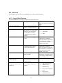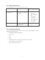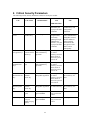
1
FIPS 140-2 Non-Proprietary Security Policy
for Aruba AP-65, AP-70, and AP-85
Wireless Access Points
Version 1.1
February 27, 2009
Aruba Networks™
1322 Crossman Ave.
Sunnyvale, CA 94089-1113
1
1
INTRODUCTION .................................................................................................................................4
1.1
2
ACRONYMS AND ABBREVIATIONS ................................................................................................... 4
PRODUCT OVERVIEW......................................................................................................................5
2.1
AP-65.............................................................................................................................................. 5
2.1.1
Physical Description............................................................................................................... 5
2.1.1.1
Dimensions/Weight ............................................................................................................ 5
2.1.1.2
Interfaces ............................................................................................................................ 5
2.1.1.3
Indicator LEDs ................................................................................................................... 6
2.2
AP-70.............................................................................................................................................. 6
2.2.1
Physical Description............................................................................................................... 7
2.2.1.1
Dimensions/Weight ............................................................................................................ 7
2.2.1.2
Interfaces ............................................................................................................................ 7
2.2.1.3
Indicator LEDs ................................................................................................................... 8
2.3
AP-85 SERIES .................................................................................................................................. 8
2.3.1
3
4
Physical Description............................................................................................................... 9
2.3.1.1
Dimensions/Weight ............................................................................................................ 9
2.3.1.2
AP 85 Interfaces ................................................................................................................. 9
2.3.1.3
Indicator LEDs ................................................................................................................. 10
MODULE OBJECTIVES...................................................................................................................11
3.1
SECURITY LEVELS ......................................................................................................................... 11
3.2
PHYSICAL SECURITY ..................................................................................................................... 11
3.2.1
AP-65 TEL Placement .......................................................................................................... 12
3.2.2
AP-70 TEL Placement .......................................................................................................... 13
3.2.3
AP-85 TEL Placement .......................................................................................................... 14
3.2.4
Inspection/Testing of Physical Security Mechanisms ........................................................... 16
3.3
MODES OF OPERATION .................................................................................................................. 16
3.4
OPERATIONAL ENVIRONMENT....................................................................................................... 17
3.5
LOGICAL INTERFACES ................................................................................................................... 17
ROLES, AUTHENTICATION, AND SERVICES...........................................................................19
4.1
ROLES ........................................................................................................................................... 19
4.1.1
Crypto Officer Authentication .............................................................................................. 19
4.1.2
User Authentication.............................................................................................................. 19
4.1.3
Wireless Client Authentication ............................................................................................. 19
4.1.4
Strength of Authentication Mechanisms ............................................................................... 19
4.2
4.2.1
SERVICES ...................................................................................................................................... 21
Crypto Officer Services......................................................................................................... 21
2
5
4.2.2
User Services ........................................................................................................................ 22
4.2.3
Wireless Client Services ....................................................................................................... 23
4.2.4
Unauthenticated Services ..................................................................................................... 23
CRYPTOGRAPHIC KEY MANAGEMENT...................................................................................24
5.1
IMPLEMENTED ALGORITHMS ......................................................................................................... 24
6
CRITICAL SECURITY PARAMETERS.........................................................................................25
7
SELF TESTS........................................................................................................................................28
3
1 Introduction
This document constitutes the non-proprietary Cryptographic Module Security Policy for the AP-65, AP70, and AP-85 series Wireless Access Points with FIPS 140-2 Level 2 validation from Aruba Networks.
This security policy describes how the AP meets the security requirements of FIPS 140-2 Level 2, and how
to place and maintain the AP in a secure FIPS 140-2 mode. This policy was prepared as part of the FIPS
140-2 Level 2 validation of the product.
FIPS 140-2 (Federal Information Processing Standards Publication 140-2, Security Requirements for
Cryptographic Modules) details the U.S. Government requirements for cryptographic modules. More
information about the FIPS 140-2 standard and validation program is available on the National Institute of
Standards and Technology (NIST) Web-site at:
http://www.nist.gov/cmvp
This document can be freely distributed.
1.1 Acronyms and Abbreviations
AES
AP
CBC
CLI
CO
CSEC
CSP
ECO
EMC
EMI
FE
GE
GHz
HMAC
Hz
IKE
IPsec
KAT
KEK
L2TP
LAN
LED
SHA
SNMP
SPOE
TEL
TFTP
WLAN
Advanced Encryption Standard
Access Point
Cipher Block Chaining
Command Line Interface
Crypto Officer
Communications Security Establishment Canada
Critical Security Parameter
External Crypto Officer
Electromagnetic Compatibility
Electromagnetic Interference
Fast Ethernet
Gigabit Ethernet
Gigahertz
Hashed Message Authentication Code
Hertz
Internet Key Exchange
Internet Protocol security
Known Answer Test
Key Encryption Key
Layer-2 Tunneling Protocol
Local Area Network
Light Emitting Diode
Secure Hash Algorithm
Simple Network Management Protocol
Serial & Power Over Ethernet
Tamper-Evident Label
Trivial File Transfer Protocol
Wireless Local Area Network
4
2 Product Overview
This section introduces the various Aruba Wireless Access Points, providing a brief overview and summary
of the physical features of each model covered by this FIPS 140-2 security policy.
2.1 AP-65
This section introduces the Aruba AP-65 Wireless Access Points (APs) with FIPS 140-2 Level 2 validation.
It describes the purpose of the AP, its physical attributes, and its interfaces.
Figure 1 - AP-65 Series Wireless Access Point
The AP-65 access point supports diverse deployment options, delivering secure user-centric network
services and applications for high-performance enterprise and campus environments, branch offices and
retail spaces, as well as deployments over public and private networks as a Remote/Mobile AP. The AP-65
supports dual, integral, high-performance omni-directional multi-band antennas.
2.1.1 Physical Description
The Aruba AP-65 Wireless Access Point is a multi-chip standalone cryptographic module consisting of
hardware and software, all contained in a hard plastic case. The module contains IEEE 802.11a and
802.11b/g transceivers, and 2 integrated omni-directional multi-band dipole antenna elements are
attached.
The plastic case physically encloses the complete set of hardware and software components, and represents
the cryptographic boundary of the module.
The evaluated hardware version is designated as AP-65-F1: Rev 01.
The evaluated firmware version is designated as ArubaOS 3.3.2-FIPS.
2.1.1.1
Dimensions/Weight
The AP has the following physical dimensions:
•
3.9” x 3.9” x 1.4” (99mm x 99mm x 36mm)
•
0.4lb (0.18 Kgs)
2.1.1.2
Interfaces
The module provides the following network interfaces:
•
1x 10/100 Base-T Ethernet (RJ45) Auto-sensing link speed and MDI/MDX.
5
The module provides the following output-only serial interface for status information:
•
1 x RJ-45 console interface, shares port with ENET
The module provides the following power interfaces:
•
48V DC 802.3af or 802.3at or PoE + interoperable Power-over-Ethernet (PoE) with intelli-source
PSE sourcing intelligence
•
5V DC for external AC supplied power (adapter sold separately)
2.1.1.3
Indicator LEDs
There are 4 single-color LEDs which operate as follows:
PORT
PWR
ENET
WLAN (a
and b/g)
COLOR
STATE
CONTROL
MEANING
Off
Off
No power
Green
On
SW
Ready for operation
Green
Blinking
SW
Not ready
Off
Off
E-net transceiver
No link
Green
On
E-net transceiver
Link okay
Green
Blinking
E-net transceiver
Link activity
Off
Off
Wireless MAC
Link disabled
Green
Very slow blink
Wireless MAC
No association
Green
Slow blink
Wireless MAC
Association, no activity
Green
Fast blink
Wireless MAC
Association and activity
Table 1- Indicator LEDs
2.2 AP-70
This section introduces the Aruba AP-70 Wireless Access Points (APs) with FIPS 140-2 Level 2 validation.
It describes the purpose of the AP, its physical attributes, and its interfaces.
6
Figure 2 - AP-70 Series Wireless Access Points
The AP-70 access point supports diverse deployment options, delivering secure user-centric network
services and applications in enterprise and campus environments, branch offices, retail spaces, and to
remote locations over public or private networks as an advanced featured Remote AP. The AP-70 provides
dual 10/100 Ethernet Interfaces, redundant 802.3af PoE sourcing, and a USB 2.0 interface (disabled for
FIPS) for service extension. The AP-70 features onboard dual, integral, high-performance omni-directional
multi-band antennas and also supports external antennas through quad, detachable antenna interfaces.
2.2.1 Physical Description
The Aruba AP-70 Wireless Access Point is a multi-chip standalone cryptographic module consisting of
hardware and software, all contained in a hard plastic case. The module contains IEEE 802.11a, 802.11b,
and 802.11g transceivers, and 2 integrated omni-directional multi-band dipole antenna elements may be
attached to the module.
The plastic case physically encloses the complete set of hardware and software components and represents
the cryptographic boundary of the module.
The evaluated hardware version is designated as AP-70-F1: Rev 01.
The evaluated firmware version is designated as ArubaOS 3.3.2-FIPS.
2.2.1.1
Dimensions/Weight
The AP has the following physical dimensions:
•
7.4” x 6.8” x 1.4” (188mm x 173mm x 36mm)
•
1.15lb (0.52 Kgs)
2.2.1.2
Interfaces
The module provides the following network interfaces:
•
2 x 10/100 Base-T Ethernet (RJ45) Auto-sensing link speed and MDI/MDX
•
Antenna
The module provides the following power interfaces:
•
48V DC 802.3af or 802.3at or PoE + interoperable Power-over-Ethernet (PoE) with intelli-source
PSE sourcing intelligence (shared over both Ethernet ports)
•
1 x 5V DC up to 2.5A for external AC supplied power (adapter sold separately)
The module provides the following additional interfaces:
•
1 x USB 2.0 interface for service extension (disabled in FIPS mode by covering with a TEL)
•
1 x RJ-45 Serial-over-Ethernet (output only, shared with ENET0 interface)
7
2.2.1.3
Indicator LEDs
There are 2 sets of 4 single-color LEDs (one on each side of the device just below the external antenna
connectors) which operate as follows:
PORT
PWR
ENET
WLAN (a
and b/g)
COLOR
STATE
CONTROL
MEANING
Off
Off
No power
Green
On
SW
Ready for operation
Green
Blinking
SW
Not ready
Off
Off
E-net transceiver
No link
Green
On
E-net transceiver
Link okay
Green
Blinking
E-net transceiver
Link activity
Off
Off
Wireless MAC
Link disabled
Green
Very slow blink
Wireless MAC
No association
Green
Slow blink
Wireless MAC
Association, no activity
Green
Fast blink
Wireless MAC
Association and activity
Table 2 - indicator LEDs
2.3 AP-85 Series
This section introduces the Aruba AP-85 Wireless Access Points (APs) with FIPS 140-2 Level 2 validation.
This series includes the AP-85TX, AP-85LX, and AP-85FX. It describes the purpose of the AP, its
physical attributes, and its interfaces.
Figure 3 - AP-85 Series Wireless Access Points
The Aruba AP-85FX, AP-85LX and AP-85TX are fully-hardened, outdoor-rated, dual (high-power) radio
(dual-band concurrent 802.11a plus b/g) wireless access points, capable of supporting multiple functions
including WLAN access, air monitoring/wireless intrusion detection and prevention, high-performance
secure outdoor enterprise mesh and LAN bridging across the 2.4-2.5 GHz and 5 GHz RF spectrums. The
AP-85FX and the AP-85LX incorporate fiber optic network interfaces(FX multi-mode / LX single-mode)
and are designed to operate from 90-288VAC mains power or +12VDC solar or vehicle battery power,
while the AP-85TX operates from standard 802.3af compliant Power-over-Ethernet (PoE) or +12VDC
solar or vehicle battery supplied power.
All models of the AP-85 access point support diverse deployment options, delivering secure user-centric
enterprise network services and applications outdoors on campuses and storage yards, in indoor and
outdoor warehouses and in extreme industrial production environments where exposure to corrosive
substances, salt water, excessive moisture or flammable gases are often encountered in daily operation.
8
Additionally, the AP-85FX and the AP-85LX are suited for use around metro city environments; where the
available street light power tap kit allows the device to be powered directly from street lighting poles.
2.3.1 Physical Description
The Aruba AP-85 series Access Point is a multi-chip standalone cryptographic module consisting of
hardware and software, all contained in a robust metal case. The module contains IEEE 802.11a and
802.11b/g transceivers, and up to 3 integrated or external omni-directional multi-band dipole antenna
elements may be attached to the module.
The metal case physically encloses the complete set of hardware and software components and represents
the cryptographic boundary of the module.
The evaluated hardware versions are designated as
•
AP-85FX-F1: Rev 01
•
AP-85LX-F1: Rev 01
•
AP-85TX-F1: Rev 01
The evaluated firmware version is designated as ArubaOS 3.3.2-FIPS.
2.3.1.1
Dimensions/Weight
The AP has the following physical dimensions:
•
10.8” x 12.64” x 3.07” (261mm x 321mm x 78mm)
•
4.1lbs (1.86 Kgs)
2.3.1.2
AP 85 Interfaces
The module provides the following network interfaces:
•
•
•
•
AP 85 FX
o
1 x 100 Base-FX multi-mode 1310nM wavelength dual-fiber LC interface
o
1 x RJ-45 console interface
AP 85 LX
o
1 x 100 Base-LX single-mode 1310nM wavelength dual-fiber LC interface
o
1 x RJ-45 console interface
AP 85 TX
o
1 x 10/100 Base-T Ethernet Auto-sensing link speed and MDI/MDX
o
48V DC IEEE compliant 802.3af Power-over-Ethernet (PoE)
o
Serial-over-Ethernet (SoE)
Antenna
o
4 x N-type female interfaces (2 per radio)
The module provides the following power interfaces:
•
AP 85 TX
9
•
2.3.1.3
o
48V DC 802.3af Power over Ethernet (PoE) (Maximum power draw 12 W at 48 V DC)
o
1 x 12V DC for external DC solar supplied power
85 FX/LX
o
1 x 90-288 VAC/500mA auto-sensing interface
o
1 x 12V DC for external DC solar supplied power
Indicator LEDs
Label
Function
Action
Status
PWR
AP power / ready status
Off
No power to AP
Flashing
Device booting, not ready
On
Device ready
Off
Ethernet link unavailable
On - Yellow
10Mbs Ethernet link negotiated
On - Green
100Mbs Ethernet link negotiated
Flashing
Ethernet link activity
Off
2.4GHz radio disabled
On - Green
2.4GHz radio enabled in WLAN
mode
On - Yellow
2.4GHz radio enabled in WDS
mode
Off
5GHz radio disabled
On - Green
5GHz radio enabled in WLAN
mode
On - Yellow
5GHz radio enabled in WDS
mode
Off
RSSI disabled / no reading
Min. 7 Step
Progressive
Bars
Increase in RSSI signal strength
= displayed bar level
ENET
Ethernet Network Link Status
/ Activity
WLAN G
WLAN A
RSSI
max)
(min-
2.4GHz Radio Status
5GHz Radio Status
RSSI Level (bridge link mode
only)
Table 3- Indicator LEDs
10
3 Module Objectives
This section describes the assurance levels for each of the areas described in the FIPS 140-2 Standard. In
addition, it provides information on placing the module in a FIPS 140-2 approved configuration.
3.1 Security Levels
Section Section Title
Level
1
Cryptographic Module Specification
2
2
Cryptographic Module Ports and Interfaces
2
3
Roles, Services, and Authentication
2
4
Finite State Model
2
5
Physical Security
2
6
Operational Environment
7
Cryptographic Key Management
2
8
EMI/EMC
2
9
Self-tests
2
10
Design Assurance
2
11
Mitigation of Other Attacks
N/A
N/A
3.2 Physical Security
The Aruba Wireless AP is a scalable, multi-processor standalone network device and is enclosed in a robust
plastic or metal housing. The AP enclosure is resistant to probing (please note that this feature has not been
tested as part of the FIPS 140-2 validation) and is opaque within the visible spectrum. The enclosure of the
AP has been designed to satisfy FIPS 140-2 Level 2 physical security requirements.
For physical security, the AP requires Tamper-Evident Labels (TELs) to allow detection of the opening of
the device, and to block the serial console port (on the bottom of the device). To protect the device from
tampering, TELs should be applied by the Crypto Officer as pictured below:
11
3.2.1 AP-65 TEL Placement
Following is the TEL placement for the AP-65:
1
2
3
12
3.2.2 AP-70 TEL Placement
Following is the TEL placement for the AP-70:
1
3
2
4
5
13
3.2.3 AP-85 TEL Placement
Following is the TEL placement for the AP-85:
2
1
3
4
5
6
7
Note: The TELs placed over the antenna interface connectors in the preceding illustration are intended to
prevent the antenna connections from being pushed into the enlosure.
14
TEL placement for an AP-85FX/LX with console cable connected:
8
TEL placement for an AP-85FX/LX with cap over console connector:
8
TEL placement for an AP-85TX with cap over Ethernet connector:
8
15
3.2.4 Inspection/Testing of Physical Security Mechanisms
Physical Security Mechanism
Recommended Test Frequency
Guidance
Tamper-evident labels (TELs)
Once per month
Examine for any sign of removal,
replacement, tearing, etc. See
images above for locations of
TELs
Opaque module enclosure
Once per month
Examine module enclosure for
any evidence of new openings or
other access to the module
internals.
3.3 Modes of Operation
The module supports multiple FIPS approved modes of operation, including the Mesh Point mode, Mesh
Portal mode, and Remote AP mode, as well as a non-approved mode. This section explains how to place
the module in FIPS mode, and how to verify that it is in this mode.
The access point is managed by an Aruba Mobility Controller, and access to the Mobility Controller’s
administrative interface via a non-networked general purpose computer is required to assist in placing the
module in FIPS mode. The controller used to provision the AP is referred to below as the “staging
controller”. The staging controller must be provisioned with the appropriate firmware image for the
module, which has been validated to FIPS 140-2 and issued certificates #1075 or #1077, prior to initiating
AP provisioning.
After setting up the Access Point by following the basic installation instructions in the module User
Manual, the Crypto Officer performs the following steps:
1.
Apply TELs according to the directions in section 3.2
2.
Log into the administrative console of the staging controller
3.
Create a Remote AP or Mesh AP profile. Note that the AP85FX/LX/TX SHALL NOT be used in
Remote AP mode. For detailed instructions on creating a Remote AP profile, see Volume 3,
“Configuring APs”, Section 7, “Configuring Remote APs” in the module User Manual. For
detailed instructions on creating a Mesh AP profile, see Volume 3, “Configuring APs”, Section 6,
“Configuring Secure Enterprise Mesh”.
a.
Configure an IKE pre-shared key which is at least 8 characters in length; generation of
such keys is outside the scope of this policy
b.
For mesh configurations, configure a WPA2 PSK which is 16 ASCII characters or 64
hexadecimal digits in length; generation of such keys is outside the scope of this policy
4.
Enable FIPS mode on the controller. This is accomplished by going to the Configuration >
Network > Controller > System Settings page (this is the default page
when you click the Configuration tab), and clicking the FIPS Mode for
Mobility Controller Enable checkbox.
5.
Enable FIPS mode on the AP. This accomplished by going to the Configuration >
Wireless > AP Configuration > AP Group page. There, you click the Edit
button for the appropriate AP group, and then select AP > AP System
Profile. Then, check the ‘‘Fips Enable’’ box, check ‘‘Apply’’, and save the
configuration.
16
6.
If the staging controller does not provide PoE, either ensure the presence of a PoE injector for the
LAN connection between the module and the controller, or ensure the presence of a DC power
supply appropriate to the particular model of the module
7.
Connect the module via an Ethernet cable to the staging controller; note that this should be a direct
connection, with no intervening network or devices; if PoE is being supplied by an injector, this
represents the only exception. That is, nothing other than a PoE injector should be present between
the module and the staging controller.
8.
Once the module is connected to the controller by the Ethernet cable, navigate to the
Configuration > Wireless > AP Installation page, where you should see an entry
for the AP. Select that AP, click the “Provision” button, and then click “Apply and Reboot” to
complete the provisioning process. During the provisioning process, the IKE pre-shared key and
WPA2 PSK are input to the module. In the initial provisioning of an AP, these keys will be
entered in plaintext; subsequently, during provisioning, they will be entered encrypted over the
secure IPSec session. For more detail on this process, see Volume 3, “Configuring APs”, Section
5, “Configuring Access Points” in the module User Manual.
9.
Via the logging facility of the staging controller, ensure that the module (the AP) is successfully
provisioned with firmware and configuration
10. Terminate the administrative session
11. Disconnect the module from the staging controller, and install it on the deployment network; when
power is applied, the module will attempt to discover and connect to an Aruba Mobility Controller
on the network using IPsec.
To verify that the module is in FIPS mode, do the following:
1.
Log into the administrative console of the Aruba Mobility Controller
2.
Verify that the module is connected to the Mobility Controller
3.
Verify that the module has FIPS mode enabled by issuing command “show ap ap-name <apname> config”
4.
Terminate the administrative session
3.4 Operational Environment
The operational environment is non-modifiable. The Operating System (OS) is Linuz, a real-time multithreaded operating system that supports memory protection between processes. Access to the underlying
Linux implementation is not provided directly. Only Aruba-provided Crypto Officer interfaces are used.
There is no user interface provided.
3.5 Logical Interfaces
The physical interfaces are divided into logical interfaces defined by FIPS 140-2 as described in the
following table.
FIPS 140-2 Logical Interface
Module Physical Interface
Data Input Interface
10/100/1000 Ethernet Ports
Fiber ports (AP85 FX/LX only)
802.11a/b/g/n Radio Transceiver
17
FIPS 140-2 Logical Interface
Module Physical Interface
Data Output Interface
10/100/1000 Ethernet Ports
Fiber ports (AP85 FX/LX only)
802.11a/b/g/n Radio Transceiver
Control Input Interface
10/100/1000 Ethernet Ports (PoE)
Fiber ports (AP85 FX/LX only)
5V power input jack
Status Output Interface
10/100/1000 Ethernet Ports
Fiber ports (AP85 FX/LX only)
802.11a/b/g/n Radio Transceiver
RJ-45 serial console interface
LEDs
Power Interface
Power Supply
PoE
Table 4 - FIPS 140-2 Logical Interfaces
Data input and output, control input, status output, and power interfaces are defined as follows:
•
Data input and output are the packets that use the networking functionality of the module.
•
Control input consists of manual control inputs for power and reset through the power interfaces
(5V DC or PoE). It also consists of all of the data that is entered into the access point while using
the management interfaces.
•
Status output consists of the status indicators displayed through the LEDs, the status data that is
output from the module while using the management interfaces, and the log file.
o
•
LEDs indicate the physical state of the module, such as power-up (or rebooting),
utilization level, and activation state. The log file records the results of self-tests,
configuration errors, and monitoring data.
A power supply may be used to connect the electric power cable. Operating power may also be
provided via Power Over Ethernet (POE) device when connected. The power is provided through
the connected Ethernet cable.
The module distinguishes between different forms of data, control , and status traffic over the network ports
by analyzing the packet headers and contents.
18
4 Roles, Authentication, and Services
4.1 Roles
The module supports the roles of Crypto Officer, User, and Wireless Client; no additional roles (e.g.,
Maintenance) are supported. Administrative operations carried out by the Aruba Mobility Controller map
to the Crypto Officer role. The Crypto Officer has the ability to configure, manage, and monitor the
module, including the configuration, loading, and zeroization of CSPs.
Defining characteristics of the roles depend on whether the module is configured as a Remote AP or as a
Mesh AP:
•
•
Remote AP:
o
Crypto Officer role: the Crypto Officer role is the Aruba Mobility Controller that has the
ability to configure, manage, and monitor the module, including the configuration,
loading, and zeroization of CSPs.
o
User role: in the standard configuration, the User operator shares the same services and
authentication techniques as the Mobility Controller in the Crypto Officer role.
o
Wireless Client role: in an advanced Remote AP configuration, a wireless client can
create a connection to the module using WPA2-PSK. The Wireless Client can access
wireless bridging services.
Mesh AP (Mesh Point or Mesh Portal configuration):
o
Crypto Officer role: the Crypto Officer role is the Aruba Mobility Controller that has the
ability to configure, manage, and monitor the module, including the configuration,
loading, and zeroization of CSPs.
o
User role: the second (or third, or nth) AP in a given mesh cluster
4.1.1 Crypto Officer Authentication
The Aruba Mobility Controller implements the Crypto Officer role. Connections between the module and
the mobility controller are protected using IPsec. Crypto Officer authentication is accomplished via proof
of possession of the IKE preshared key, which occurs during the IKE key exchange.
4.1.2 User Authentication
Authentication for the User role depends on the module configuration. When the module is configured as a
Mesh AP, the User role is authenticated via the WPA2 preshared key. When the module is configured as a
Remote AP, the User role is authenticated via the same IKE pre-shared key that is used by the Crypto
Officer.
4.1.3 Wireless Client Authentication
The wireless client role, in the Remote AP advanced configuration authenticates to the module via the
WPA2 preshared key. Note that when the Remote AP advanced configuration options are used, WPA2PSK must be used for authentication. WEP and/or Open System configurations are not permitted in FIPS
mode.
4.1.4 Strength of Authentication Mechanisms
The following table describes the relative strength of each supported authentication mechanism.
19
Authentication Mechanism Strength
Mechanism
IKE shared secret
(CO role)
For IKE, there are a 95^8 (=6.63 x 10^15) possible preshared keys. In order to
test the guessed key, the attacker must complete an IKE aggressive mode
exchange with the module. IKE aggressive mode consists of a 3 packet
exchange, but for simplicity, let’s ignore the final packet sent from the AP to
the attacker.
An IKE aggressive mode initiator packet with a single transform, using DiffieHellman group 2, and having an eight character group name has an IKE packet
size of 256 bytes. Adding the eight byte UDP header and 20 byte IP header
gives a total size of 284 bytes (2272 bits).
The response packet is very similar in size, except that it also contains the
HASH_R payload (an additional 16 bytes), so the total size of the second
packet is 300 bytes (2400 bits).
Assuming a link speed of 1Gbits/sec (this is the maximum rate supported by the
module), this gives a maximum idealized guessing rate of 60,000,000,000 /
4,672 = 12,842,466 guesses per minute. This means the odds of guessing a
correct key in one minute is less than 12,842,466/(6.63x10^15) = 1.94 x 10^-9,
which is much less than 1 in 10^5.
Mesh AP WPA2
PSK (User role)
For WPA-PSK there are at least 95^16 (=4.4 x 10^31) possible combinations.
In order to test a guessed key, the attacker must complete the 4-way handshake
with the AP. Prior to completing the 4-way handshake, the attacker must
complete the 802.11 association process. That process involves the following
packet exchange:
•
Attacker sends Authentication request (at least 34 bytes)
•
AP sends Authentication response (at least 34 bytes)
•
Attacker sends Associate Request (at least 36 bytes)
• AP sends Associate Response (at least 36 bytes)
Total bytes sent: at least 140. Note that since we do not include the actual 4way handshake, this is less than half the bytes that would actually be sent, so
the numbers we derive will absolutely bound the answer.
The theoretical bandwidth limit for IEEE 802.11n is 300Mbit, which is
37,500,000 bytes/sec. In the real world, actual throughput is significantly less
than this, but we will use this idealized number to ensure that our estimate is
very conservative.
This means that the maximum number of associations (assume no delays, no
inter-frame gaps) that could be completed is less than 37,500,000/214 =
267,857 per second, or 16,071,429 associations per minute. This means that an
attacker could certainly not try more than this many keys per second (it would
actually be MUCH less, due to the added overhead of the 4-way handshake in
each case), and the probability of a successful attack in any 60 second interval
MUST be less than 16,071,429/(4.4 x 10^31), or roughly 1 in 10^25, which is
much, much less than 1 in 10^5.
Wireless Client
WPA2 PSK
(Wireless Client
Role)
WPA2 preshared keys are subject to the same analysis as WPA-PSK, above.
20
4.2 Services
The module provides various services depending on role. These are described below.
4.2.1 Crypto Officer Services
The following Module Services are provided for the Crypto Officer role:
Service
Description
CSPs Accessed (see section 6
below for complete description of
CSPs)
FIPS mode enable/disable
The CO selects/de-selects FIPS
mode as a configuration option.
Key Management
The CO can configure/modify the
IKE shared secret and the WPA2
PSK. Also, the CO implicitly
uses the KEK to read/write
configuration to non-volatile
memory.
None.
•
IKE shared secret
•
WPA2 PSK
•
KEK
Remotely reboot module
The CO can remotely trigger a
reboot
KEK is accessed when
configuration is read during
reboot. The firmware verification
key and firmware verification CA
key are accessed to validate
firmware prior to boot.
Self-test triggered by CO reboot
The CO can trigger a
programmatic reset leading to
self-test and initialization
KEK is accessed when
configuration is read during
reboot. The firmware verification
key and firmware verification CA
key are accessed to validate
firmware prior to boot.
Update module firmware
The CO can trigger a module
firmware update
The firmware verification key
and firmware verification CA key
are accessed to validate firmware
prior to writing to flash.
Configure non-security related
module parameters
CO can configure various
operational parameters that do not
relate to security
None.
Creation/use of secure
management session between
module/CO
The module supports use of IPsec
for securing the management
channel.
•
IKE Preshared Secret
•
DH Private Key
•
DH Public Key
•
IPsec session encryption
keys
•
IPsec session
authentication keys
21
Service
Description
CSPs Accessed (see section 6
below for complete description of
CSPs)
Creation/use of secure mesh
channel
System Status
The module requires secure
connections between mesh points
using 802.11i
CO may view system status
information through the secured
management channel
•
WPA2-PSK
•
802.11i PMK
•
802.11i PTK
•
802.11i EAPOL MIC
Key
•
802.11i EAPOL
Encryption Key
•
802.11i AES-CCM key
•
802.11i GMK
•
802.11i GTK
•
802.11i AES-CCM key
See creation/use of secure
management session above.
4.2.2 User Services
The following Module Services are provided for the User role:
Service
Description
CSPs Accessed (see section 6
below for complete description of
CSPs)
Generation and use of 802.11i
cryptographic keys
Use of WPA preshared key for
establishment of IEEE 802.11i
keys
When the module is in mesh
configuration, the inter-module
mesh links are secured with
802.11i.
When the module is in mesh
configuration, the inter-module
mesh links are secured with
802.11i. This is authenticated
with a shared secret
•
802.11i PMK
•
802.11i PTK
•
802.11i EAPOL MIC
Key
•
802.11i EAPOL
Encryption Key
•
802.11i AES-CCM key
•
802.11i GMK
•
802.11i GTK
•
WPA2 PSK
For Remote AP mode User services, please refer to Section 4.2.1, “Crypto Officer Services”
22
4.2.3 Wireless Client Services
The following Module Services are provided for the Wireless Client role:
Service
Description
CSPs Accessed (see section 6
below for complete description of
CSPs)
Generation and use of 802.11i
cryptographic keys
Wireless bridging services
For creation of secure channel
between the wireless client and
the module
The module bridges traffic
between the wireless client and
the wired network
•
802.11i PMK
•
802.11i PTK
•
802.11i EAPOL MIC
Key
•
802.11i EAPOL
Encryption Key
•
802.11i AES-CCM key
•
802.11i GMK
•
802.11i GTK
•
None
4.2.4 Unauthenticated Services
The module provides the following unauthenticated services, which are available regardless of role. No
CSPs are accessed by these services.
•
System status – SYSLOG and module LEDs
•
802.11 a/b/g/n
•
FTP
•
TFTP
•
NTP
•
GRE tunneling of 802.11 wireless user frames (when acting as a “Local AP”)
•
Reboot module by removing/replacing power
•
Self-test and initialization at power-on
23
5 Cryptographic Key Management
5.1 Implemented Algorithms
The firmware implementation is performed using OpenSSL FIPS crypto library version 1.1.1, the Linux
kernel cryptographic module, and the IDT bootloader. The firmware implements the following FIPSapproved algorithms:
•
•
•
OpenSSL
o
AES (Cert. #900) - CBC: 128, 192, 256 bits
o
Triple-DES (Cert. #734)- CBC key options Keying Options 1,2,3 used
o
SHA-1 (Cert. #892) - BYTE oriented
o
HMAC SHA-1 (Cert. #503)
o
RSA (Cert. #436)
o
RNG (Cert. #516)
Linux kernel cryptographic module
o
AES (Cert. #895) - CCM: 128 bits
o
Triple-DES (Cert. #731)- CBC key options Keying Options 1,2,3 used
o
SHA-1 (Cert. #887) - BYTE oriented
o
HMAC SHA-1 (Cert. #500)
IDT Bootloader cryptographic module
o
SHA-1 (Cert. #888) - BYTE oriented
o
RSA (Cert. #433)
The firmware implements the following non-FIPS-approved algorithms in firmware:
•
MD5
The firmware implements the following non-approved but allowed algorithms in firmware:
•
Diffie-Hellman
Diffie-Hellman key establishment methodology provides 80-bits of encryption strength.
24
6 Critical Security Parameters
The following Critical Security Parameters (CSPs) are used by the module:
STORAGE
CSP
CSP TYPE
GENERATION
And
USE
ZEROIZATION
KEK
TDES key
Hard-coded
Stored in flash.
Zeroized by the
‘ap wipe out flash’
command.
Encrypts IKE
preshared keys and
configuration
parameters
IKE Pre-shared
secret
64 character
preshared key
Externally generated
Encrypted in flash
using the KEK;
zeroized by
updating through
administrative
interface, or by the
‘ap wipe out flash’
command.
Module and crypto
officer authentication
during IKE; entered
into the module in
plaintext during
initialization and
encrypted over the
IPSec session
subsequently.
IPsec session
encryption keys
168-bit TDES,
128/192/256 bit
AES keys;
Established during
Diffie-Hellman key
agreement
Stored in plaintext
in volatile
memory; zeroized
when session is
closed or system
powers off
Secure IPsec traffic
IPsec session
authentication
keys
HMAC SHA-1
keys
Established during
Diffie-Hellman key
agreement
Stored in plaintext
in volatile
memory; zeroized
when session is
closed or system
powers off
Secure IPsec traffic
IKE DiffieHellman Private
key
1024-bit DiffieHellman
private key
Generated internally
during IKE negotiation
Stored in plaintext
in volatile
memory; zeroized
when session is
closed or system is
powered off
Used in establishing
the session key for
IPsec
IKE DiffieHellman public
key
1024-bit DiffieHellman
private key
Generated internally
during IKE negotiation
Stored in plaintext
in volatile memory
Used in establishing
the session key for
IPsec
PRNG seeds
PRNG Seed (8
bytes)
Generated by nonapproved PRNG
In volatile memory
only; zeroized on
reboot
Seed PRNG
PRNG Keys
PRNG Keys
(16 bytes,
TDES 2-keying
option)
Generated by nonapproved PRNG
In volatile memory
only; zeroized on
reboot
PRNG operation
25
STORAGE
CSP
CSP TYPE
GENERATION
And
USE
ZEROIZATION
WPA2 PSK
16-64 character
shared secret
used to
authenticate
mesh
connections
and in remote
AP advanced
configurations
Externally generated
Encrypted in flash
using the KEK;
zeroized by
updating through
administrative
interface, or by the
‘ap wipe out flash’
command.
Used to derive the
PMK for 802.11i
mesh connections
between APs and in
advanced Remote AP
connections; entered
into the module in
plaintext during
initialization and
encrypted over the
IPSec session
subsequently.
802.11i
Pairwise Master
Key (PMK)
512-bit shared
secret used to
derive 802.11i
session keys
Internally generated
using WPA PSK
In volatile memory
only; zeroized on
reboot
Used to derive
802.11i Pairwise
Transient Key (PTK)
for mesh connections
between APs
802.11i
Pairwise
Transient Key
(PTK)
512-bit shared
secret from
which
Temporal Keys
(TKs) are
derived
Derived during 802.11i
4-way handshake
In volatile memory
only; zeroized on
reboot
All session
encryption/decryption
keys are derived from
the PTK
802.11i
128-bit shared
secret used to
protect 4-way
(key)
handshake
Derived from PTK
In volatile memory
only; zeroized on
reboot
Used for integrity
validation in 4-way
handshake
802.11i EAPOL
Encr Key
128-bit shared
secret used to
protect 4-way
handshakes
Derived from PTK
In volatile memory
only; zeroized on
reboot
Used for
confidentiality in 4way handshake
802.11i data
AES-CCM
encryption/mic
key
128-bit AESCCM key
Derived from PTK
Stored in plaintext
in volatile
memory; zeroized
on reboot
Used for 802.11i
packet encryption and
integrity verification
(this is the CCMP or
AES-CCM key)
802.11i Group
Master Key
(GMK)
256-bit secret
used to derive
GTK
Internally generated
from approved RNG
Stored in plaintext
in volatile
memory; zeroized
on reboot
Used to derive Group
Transient Key (GTK)
802.11i Group
Transient Key
(GTK)
256-bit shared
secret used to
derive group
(multicast)
encryption and
integrity keys
Internally derived by
mesh AP which
assumes
“authenticator” role in
handshake
Stored in plaintext
in volatile
memory; zeroized
on reboot
Used to derive
multicast
cryptographic keys
EAPOL MIC
Key (mesh
only)
26
STORAGE
CSP
CSP TYPE
GENERATION
And
USE
ZEROIZATION
802.11i Group
AES-CCM Data
Encryption/MIC
Key
128-bit AESCCM key
derived from
GTK
Derived from 802.11
group key handshake
Stored in plaintext
in volatile
memory; zeroized
on reboot
Used to protect
multicast message
confidentiality and
integrity (AES-CCM)
Firmware
verification key
2048-bit RSA
public key
Externally generated
Stored in plaintext
in bootloader
image
Used to validate the
signature on firmware
image
Firmware CA
key
2048-bit RSA
public key
Externally generated
Stored in plaintext
in bootloader
image
Used to validate
certificate containing
Firmware verification
key
27
7 Self Tests
The module performs both power-up and conditional self-tests. In the event any self-test fails, the module
enters an error state, logs the error, and reboots automatically.
The module performs the following power-up self-tests:
•
Software Integrity Test–The module checks the integrity of its firmware by validating a 2048-bit
RSA digital signature over the image to ensure its authenticity.
•
Cryptographic Algorithm Tests – These tests are run at power-up for the TDES
encryption/decryption, AES and AES-CCM encryption/decryption, SHA-1 known answer test,
HMAC SHA-1 known answer test, RSA signature verification, and the PRNG random data
generation.
The following Conditional Self-tests are performed in the module:
•
Continuous Random Number Generator Test–This test is run upon generation of random data by
the module's random number generators to detect failure to a constant value.
These self-tests are run for the Linux kernel cryptographic implementation as well as for the OpenSSL
implementation.
Self-test results are written to the serial console.
In the event of a KATs failure, the AP logs different messages, depending on the error. For example, for an
AES kernel (software) POST failure:
Starting Kernel SHA1 KAT ...Completed Kernel SHA1 KAT
Starting Kernel HMAC-SHA1 KAT ...Completed Kernel HMAC-SHA1 KAT
Starting Kernel DES KAT ...Completed Kernel DES KAT
Starting Kernel AES KAT ...Restarting system.
For an OpenSSL KAT failure:
AP rebooted [DATE][TIME] : Restarting System, SW FIPS KAT failed
28