1
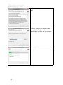
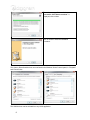
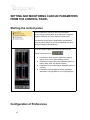
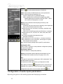
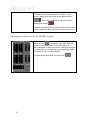
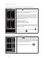
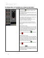
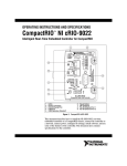
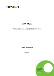
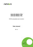
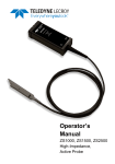
CANCUN 222-Mic
CANCUN 442-Mic
Professional USB Audio Interface
Version v1.00
User manual
1
For technical support,
please contact your supplier
www.digigram.com
Digigram S.A.
Parc de Pré Milliet, 38330 Montbonnot - FRANCE
Tel: +33 (0)4 76 52 55 01• Fax: +33 (0) 4 76 52 53 07• E-mail: [email protected]
Digigram Asia Pte Ltd.
60 Albert Street - #19-11OG Albert Complex Singapore 189969, Singapore
Tel : +65 6291 2234 • Fax : +65 6291 3433 • E-mail : [email protected]
2
INFORMATION FOR THE USER
IMPORTANT NOTICE
FEATURES
Cancun 222-Mic and CANCUN 442-Mic main hardware features
CANCUN 222-Mic
CANCUN 442-Mic
Software features
HARDWARE REQUIREMENTS
SUPPORTED OPERATING SYSTEMS
HARDWARE INSTALLATION
SOFTWARE INSTALLATION OF CANCUN UNDER WINDOWS
FIRMWARE UPDATE
SETTING AND MONITORING CANCUN PARAMETERS FROM THE CONTROL PANEL
Starting the control panel
Configuration of Preferences
Adjusting the gains on the analog inputs and displaying vu-meters
Input pad and 48V phantom power
Displaying the signal level on the AES/EBU input(s)
Adjusting the gains on the analog outputs and displaying vu-meters
Displaying the signal level on the AES/EBU output(s)
Configuration of headphone output parameters
SETTING CANCUN PARAMETERS FROM THE CANCUN TOUCH PANEL
Input gains setting
Pad
Variable analog input gain
Output gains settings
48V phantom power
SPECIFICATIONS
Configuration
Audio specifications
Inputs
Outputs
Analog audio performances
External Connectors
Delivered Cables
Environments
CANCUN 222-Mic schematic diagram
CANCUN 222-Mic CABLE
CANCUN 222-Mic cable schematic
CANCUN 222-Mic Wiring diagram
CANCUN 222-Mic cable pinout
CANCUN 442-Mic CABLE
CANCUN 442-Mic cable schematic
CANCUN 442-Mic Wiring diagram
CACUN 442-Mic cable pinout
3
INFORMATION FOR THE USER
The user’s manual or instruction manual for an intentional or unintentional radiator shall caution the user that changes or
modifications not expressly approved by the party responsible for compliance could void the user's authority to operate the
equipment
This device complies with part 15 of FCC rules. Operation is subject to the following two conditions:
(1) This device may not cause harmful interference, and (2) This device must accept any interference
received, including interference that may cause undesired operation.
This equipment has been tested and found to comply with the limits for a CLASS B digital device, pursuant
to Part 15 of the FCC Rules. These limits are designed to provide reasonable protection against harmful
interference in a residential installation. This equipment generates, uses, and can radiate radio frequency
energy and, if not installed and used in accordance with the instructions contained in this data sheet, may
cause harmful interference to radio and television communications. However, there is no guarantee that
interference will not occur in a particular installation.
If this equipment does cause harmful interference to radio or television reception, which can be determined
by turning the equipment off and on, the user is encouraged to try to correct the interference by one or
more of the following measures:
* reorient or relocate the receiving antenna
* increase the separation between the equipment and the receiver
* connect the equipment into an outlet on a circuit different from that of the receiver
* consult the dealer or an experienced audio television technician.
Note:
Connecting this device to peripheral devices that do not comply with CLASS B
requirements or using an unshielded peripheral data cable could also result in harmful interference
to radio or television reception. The user is cautioned that any changes or modifications not
expressly approved by the party responsible for compliance could void the user’s authority to
operate this equipment. To ensure that the use of this product does not contribute to interference, it
is necessary to use shielded I/O cables.
IMPORTANT NOTICE
This device has been tested and found to comply with the following standards:
·
International: CISPR22 Class B
·
Europe: EMC 89/336/CEE (1992) specifications.
·
United States: FCC Rules-Part 15-Class B (digital device).
For best compliance with these standards, Digigram recommends to use audio shielded cables shorter
than three meters.
FEATURES
CANCUN 222-Mic and CANCUN 442-Mic are professional audio interface for USB ports (compatible with
USB 2.0 and USB 3.0 hosts).
They are powered via USB.
4
CANCUN devices are delivered with a ‘Y’ USB cable allowing powering the device from two USB ports. It
is recommended to connect the two USB plugs so as to correctly power the CANCUN unit.
Cancun 222-Mic and CANCUN 442-Mic main hardware
features
●
●
●
●
●
●
●
●
●
●
●
●
Simultaneous analog & AES I/Os in a compact form factor
A/D and D/A conversions 24-bit / frequency : 32 kHz, 44.1 kHz, 48 kHz, 88.2 kHz, 96 kHz, 192
kHz
Excellent MIC preamp (55dB gain, from -60 dBu sensitivity, typical -105 dB THD+N, and -128 dB
EIN)
Switchable 48V phantom power (7 mA Max on each input)
Adjustable analog input gain from 0 to 55 dB, by 1 dB steps
Switchable -30 dB input signal Pad (level attenuator)
Maximum analog input signal: +25 dBu
Guaranteed low latency (<4 mS) on both Windows™ and Mac OSX™ platforms
Ergonomically advanced user interface for quick setup and efficient monitoring on both Windows™
and Mac OSX™ platforms
Innovative hardware controls with LED-lighted touch panel
Neutrik™ XLR connectivity and break-out cable
Input channel 1 duplicated on an XLR input on the CANCUN, and on the breakout cable.
CANCUN 222-Mic
·
·
·
·
·
2 balanced analog mono line/mic inputs, +25 dBu max signal level
2 balanced analog mono line outputs, +10 dBu max signal level
1 additional balanced stereo AES/EBU input
1 additional balanced stereo AES/EBU output
1 stereo headphone output on female 6.35mm jack
5
CANCUN 442-Mic
●
●
●
●
●
4 balanced analog mono line/mic inputs, +25 dBu max signal level
4 balanced analog mono line outputs, +10 dBu max signal level
2 additional balanced AES/EBU inputs
2 additional balanced AES/EBU outputs
1 stereo headphone output on female 6.35mm jack
Software features
●
●
●
●
●
●
●
●
CANCUN 222-Mic and CANCUN 442-Mic comply with the USB Audio 2.0 specification
Simultaneous record and playback on all the audio I/Os
Supported formats: PCM 8, 16, 24 bits
DirectSound devices
CANCUN 222-Mic: 2 stereo input devices (1 analog, 1 AES/EBU)
CANCUN 442-Mic: 4 stereo output devices (2 analog, 2 AES/EBU)
ASIO devices
CANCUN 222-Mic: 4 mono input devices (2 analog, 2 AES/EBU)
CANCUN 442-Mic: 8 mono output devices (4 analog, 4 AES/EBU)
Control Panel GUI for quick setup and efficient monitoring on both Windows™ and Mac OSX™(*)
platforms
Mixing of the inputs and playback ouputs to the headphone output
Host platform Control Panel synchronized with CANCUN touch panel
As Windows operating systems don’t feature the USB Audio 2.0 compatibility, it is necessary to install
a driver package. CANCUN devices are visible as DirectSound and ASIO devices. CANCUN is also
compatible with Kernel Streaming applications.
HARDWARE REQUIREMENTS
·
·
Computer with at least Pentium Core 2 Duo CPU or equivalent recommended
Two USB port (standard 2.0 or higher)
SUPPORTED OPERATING SYSTEMS
·
·
·
Windows XP, Windows Seven (32-bit and 64-bit)
Mac OS X
Linux(*)
* Not available yet. Will be available by software upgrade
HARDWARE INSTALLATION
Connect the mini-B USB connector of the provided USB cable to the mini-B USB port located underneath
CANCUN.
Connect the 2 standard type A male USB connectors of the provided USB ‘Y’cable to two USB ports (USB
2.0) or your computer.
6
It will then automatically be detected by the operating system.
Under Windows operating systems, it is necessary to install the driver package for Windows (because
Windows OS don’t support USB Audio 2.0).
●
●
Notes:
It is recommended to plug the two USB connecors of the provided ‘y’ USB cable.
It is not recommended to power CANCUN from a USB power supply.
If you have several USB peripherals connected to the same USB controller of your computer, they
may consume more energy than the USB controller can provide. In this case, disconnect some of
these peripherals.
SOFTWARE INSTALLATION OF CANCUN UNDER
WINDOWS
The first time you connect your Cancun device to your computer, it is necessary to install its driver, as USB
Audio 2.0 is not supported yet by Windows operating systems
Connect your Cancun device to a free USB port of your computer.
Execute the driver installation package you have downloaded from Digigram WEB site, and proceed as
follows.
Click on Next.
7
Accept the License Agreement, and click on
Next.
By default, driver files are installed in folder
C:\Program Files\Digigram CANCUN. Select
another folder if you want, and click on Install.
Wait during the installation of the driver.
8
When the message “Preinstallation was
successful. Click Next to continue” is
displayed, click on Next.
Click on Finish to finish the installation
procedure.
The Cancun DirectSound devices are now listed in the Windows “Sound” control panel, in “Playback”
and “Record” tabs.
The ASIO devices can be selected from any ASIO application.
9
FIRMWARE UPDATE
Your Cancun is delivered with a firmware version applied in factory. A more recent firmware version
may have been released by Digigram since you purchased your CANCUN (a new firmware may include
improvements and new features).
Please connect to the Support page of Digigram WEB site: www.digigram.com/drivers/index.php.
Select “Sound cards” in section “Product Technology”, and then select “CANCUN 222-Mic or CANCUN
442-Mic” from section “Product type”. Download the most recent firmware which has been release after
you purchased your CANCUN.
Unzip the downloaded file.
From “Start” menu, “Programs”, select “Digigram
CANCUN”, and “CANCUN Firmware Updater”.
Select the CANCUN device to be updated from the
list box “Your CANCUN device to update”. If you
have one CANCUN connected, it is selected by
default.
The version of the firmware currently used on your
CANCUN is displayed in “Firmware version”.
In case you have downloaded a more recent
firmware, select it by clicking on “Select the
Firmware image file”. Select the .bin file
(downloaded firmware file that you have unzipped).
The selected firmware file (.bin) is displayed.
Click on button “Start Update” to start the firmware
update process.
10
A confirmation window is displayed. Click on
button “Yes” to confirm the firmware update.
The displayed green bar indicates the firmware
update progress.
When the green progress bar has reached 100%
and the message “The Firmware was successfully
updated” is displayed, click on button “Exit” to quit
the firmware updater application.
You can now use your CANCUN which is running
the new firmware.
Notes:
● If the USB cable is disconnected during the firmware update process, the firmware
updater displays an error message. Re-connect the USB cable, and click again on
button “Start Update”.
● In case the firmware update fails, CANCUN is set back to the firmware version applied in
factory, even if you installed a more recent firmware version.
11
SETTING AND MONITORING CANCUN PARAMETERS
FROM THE CONTROL PANEL
Starting the control panel
Cancun parameters can be set from its control panel.
To open Cancun control panel, go in Start menu, Programs,
Digigram CANCUN, and select Cancun Control Panel.
Note that the Control Panel is automatically opened when
connecting the CANCUN to the PC (provided that the driver
has been installed under Windows).
Four main groups of parameters are accessible from the
Control Panel bottom bar:
●
●
●
●
Preferences: Clock selection, buffer size (latency),
opacity of the Control Panel display, presets.
Parameters for the audio inputs (adjustable gains, vu –
meters, Mute, PAD, 48V phantom power) .
Parameters for the audio outputs (adjustable gains, vu
–meters,)
Parameters for the headphone output (adjustable
attenuation, Left/right balance, mix of input signals).
Configuration of Preferences
12
Click on
to set the global parameters of CANCUN.
Cards: allows select the CANCUN device to set its parameters.
Clocks: allows selecting the sampling clock:
· Internal: sampling clock is generated internally
· AES1: sampling clock is extracted from digital input AES1.
Without digital signal connected to the input “AES 1”, AES1
clock selection is displayed as “not valid”.
·
Buffers: these parameters allow adjusting the latency of the
CANCUN device.
· Streaming: this is the lowest level of buffering, which impacts the
latency in DirectSound as well as in ASIO.
Possible selections are: min latency, low latency, standard, relax,
safe, extra safe.
· ASIO: this is the buffering used by the ASIO driver, in samples.
Possible values are: 64, 128, 256, 512, 1024, 2048, 4096, 8192
samples.
The minimum selectable value depends on the
parameter “Streaming”.
When “Streaming” is set to “low latency” , all values are allowed.
When “Streaming” is set to “extra safe”, values higher or equal to
2048 samples can be selected.
Note: minimum latency settings require good PC performances.
Configuration Save
Click on “Save” to save the current parameter configuration (settings
are saved as an XML file).
Configuration Restore
Click on “Restore” to load presets (XML file).
Opacity: this parameter allows adjusting the transparency of the
Control Panel GUI. Available choices are: opaque, 30%, 50%.
Note:
- This panel is opened when selecting the “ASIO configuration” from
an ASIO software application.
- Be aware that certain applications (e.g. Reaper) do not allow
direct editing of CANCUN
configuration menu; in this case, the
CANCUN menu should be accessed through the application audio
configuration menu which in turn launches CANCUN
Configuration of audio inputs parameters
Adjusting the gains on the analog inputs and displaying vu-meters
13
panel.
Click on
to set the parameters of audio inputs.
Each slider allows adjusting the analog gain for an analog input from
0dB to + 55 dB, by 1 dB steps.
It is possible to adjust the level of several inputs at the same time, by
moving only one slider. To do so, press “Shift + Click” on each slider.
The cursor of the slider becomes purple. When all the selected sliders
are purple, just move one of them. All the sliders move at the same
time
The vu-meters display the signal level after the analog to digital
conversion. The peak-meter instantaneous value is displayed right
above the vu-meter.
To mute an input, click on the corresponding Mute icon
ON when icon is red
. Mute is
.
Input pad and 48V phantom power
Click on the icon
on the top left of the ANALOG panel to
display the panel allowing to set Pad and 48V on the inputs.
Pad is a fixed attenuator stage (-30 dB) available on each
input, that can be enabled/disabled.
To enable the Pad on an input channel, click on the OFF
button on the right of PAD
for the selected channel.
When Pad is enabled on a channel, the button is displayed as
follows:
Audio alignment when Pad is OFF.
Alignment when slider is set to 0 dB: -5.2 dBu -> 0dBfs
Alignment when slider set to 55 dB: -60.2 dBu -> 0dBfs
Audio alignment when Pad is ON.
Alignment when slider is set to 0 dB: +25.6 dBu -> 0dBfs
Alignment when slider set to 55 dB: -29.4 dBu -> 0dBfs
Set Pad to OFF when using microphones.
When using static microphones, it is necessary to enable the
14
48 V phantom power on the input the mic is connected to.
To activate the 48V phantom power on an input, click on
the OFF button on the right of 48V for the concerned input:
. When 48V is enabled on an input, the button is
displayed as follows:
Note that any modification of the Pad from the software Control
Panel is reflected on the touch pad of Cancun, and vice versa.
Displaying the signal level on the AES/EBU input(s)
Click on the icon
, on the bottom right of the “ANALOG”
window, to view the digital level on the inputs signals. A vumeter is displayed for each input channel, which gives the digital
level of the signal on the digital input, expressed in dBfs (0dBfs
is the maximum value of a digital sample).
To hide the digital levels panel, click on the icon
15
.
Adjusting the gains on the analog outputs and displaying vu-meters
Click on the icon
to set the parameters for audio outputs.
For each output, the volume slider allows adjusting the analog
attenuation, 0dB to - 72 dB, by 1 dB steps.
It is possible to adjust the volume of several outputs at the same
time, by moving only one slider. To do so, press “Shift + Click”
on each slider. The cursor of the slider becomes purple. When
all the selected sliders are purple, just move one of them. All the
sliders move at the same time.
Output alignment is as follows:
Slider set to 0 dB: 0 dBfs -> +10dBu
Slider set to -72 dB: 0 dBfs -> -62dBu
The vu-meters display the signal level before the digital to analog
conversion. The peak-meter instantaneous value is displayed
right above the vu-meter.
.
To mute an output, click on the corresponding Mute icon
Mute is ON when icon is red
.
Displaying the signal level on the AES/EBU output(s)
Click on the icon
, on the bottom right of the “ANALOG”
window, to view the digital level on the outputs signals. A vumeter is displayed for each input channel, which gives the digital
level of the signal on the digital output, expressed in dBfs (0dBfs
is the maximum value of a digital sample).
To hide the digital levels panel, click on the icon
16
.
Configuration of headphone output parameters
Click on the icon
to adjust the settings of the
headphones output.
The central fader allows adjusting the signal level on
the headphones output.
The horizontal cursor, in top of the main fader, allows
adjusting the balance between left and right channels.
The heaphones output receives a mix composed of:
- all the inputs (analog and AES/EBU)
- all the audio played on CANCUN output devices
(playback from software applications).
The level of each signal on the input of the mixer
can be adjusted from the left window, as well as the
panoramic.
ANALOG INPUT section
This section allows adjusting the levels of the signals
on the analog inputs right before the mixer. For each
signal, the central fader controls the signal level, and
the upper horizontal slider controls the panoramic
between left and right output channels.
The signal can be selected in solo
muted
, and can be
.
ANALOG OUTPUT section
This section allows adjusting the levels of the signals
played on the outputs from a software application. For
each signal, the central fader controls the signal level,
and the upper horizontal slider controls the panoramic
between left and right output channels.
The signal can be selected in solo
muted
, and can be
.
Click on the icon
on the top left of the central
headphones window to access the levels adjustment
for the digital signals of the AES/EBU inputs, from the
section DIGITAL INPUT.
17
Click on the icon
on the bottom left of the
central headphones window to access the DIGITAL
OUTPUT section, for adjusting the levels of the
signals played on the AES/EBU outputs from a
software application.
18
SETTING CANCUN PARAMETERS FROM THE CANCUN
TOUCH PANEL
Input gains setting
Pad
Press the Pad touch button to enable/disable the fixed attenuation on the desired.
When PAD is ON, a green led appears. An attenuation of -30.0 dB is applied to the analog input signal.
When PAD is OFF, the LED is turned off. No attenuation is applied.
Note that the Pad status is reflected in the software Control Panel.
Variable analog input gain
The analog input gain is adjustable with the
upper rotary button when:
· the IN/OUT touch button on the right of
the rotary button is in position IN (green
led in front of IN)
· and the touch button on the left of the
rotary wheel is active (green led).
Pressing the button
several times allows
selecting analog input 1, analog input 2, both
inputs, or no input (LED turned off).
The analog gain adjustment is then applied to
the selected input(s).
Note that moving the rotary button
automatically updates the fader position in
the software control panel for the concerned
channels.
19
Output gains settings
The analog output gain is adjustable
with the upper rotary button when:
· the IN/OUT touch button on the
right of the rotary button is in
position OUT (green led in front of
OUT)
· and the touch button on the left of
the rotary wheel is active (green
led).
Pressing the button
several times
allows selecting analog output 1, analog
output 2, both outputs, or no output
(LED turned off).
The analog gain adjustment is then
applied to the selected output(s).
Note that moving the rotary button
automatically updates the fader position
in the software control panel for the
concerned channels.
48V phantom power
In case you are using a static microphone on an
analog input, it is necessary to activate the 48V
phantom power on this input.
Press the “48v” touch button of the concerned input.
48v phantom power is enabled when a red LED
appears. It is disabled otherwise.
Note: in case several static microphones are used, it
may be necessary to connect the Cancun to a second
USB controller of the PC so as to get enough current
(a single USB controller may not provide enough
current).
20
21
SPECIFICATIONS
Configuration
Bus Format
USB 2.0 / Compliant with the USB 2.0 Audio specification
Size
254 mm x 96 mm x 36 m
Operating : temp / Humidity
0°C to +50°C / 0 % to 90 % (non condensing)
Audio specifications
A/D and D/A converters
resolution
24 bits
Sampling frequencies available
32 kHz, 44.1 kHz, 48 kHz, 88.2 kHz, 96 kHz, 192 kHz
Audio formats supported
PCM 8, 16, 20, and 24 bits
Latency
3.4 mS Analog-to-PC or PC-to-Analog (Windows 7 / 64 bits)
3.8 mS Analog-to-MAC or MAC-to-Analog (Mac OS X 10.6.8)
ADAT / S/PDIF
24-bit/192kHz ADAT *
* Not available yet. Will be available by software upgrade
Inputs
Analog line inputs (mono)
Maximum input level/
impedance
Programmable input gain
Input Pad
Input sensitivity
Digital inputs (stereo)
22
CANCUN 222-Mic
CANCUN 442-Mic
2 balanced
4 balanced
Line: +25 dBu / >3.5 kOhms
Mic: -5 dBu / >2 kOhms
Line: +25 dBu / >3.5 kOhms
Mic: -5 dBu / >2 kOhms
From 0 to 55 dB by 1 dB steps
From 0 to 55 dB by 1 dB steps
- 30 dB switchable on each analog input
- 30 dB switchable on each analog input
Line (PAD On): 0 dBfs adjustable from -30
dBu to +25 dBu
Mic (PAD Off): -60 dBu to -5 dBu
Line (PAD On): 0 dBfs adjustable from -30
dBu to +25 dBu
Mic (PAD Off): -60 dBu to -5 dBu
1 AES/EBU (AES3-2003) compliant
2 AES/EBU (AES3-2003) compliant
AES11 synchronization
Other inputs
Yes, on AES 1 Input
Yes, on AES 1 Input
ADAT / S/PDIF*
ADAT / S/PDIF*
* Not implemented yet. This will be available by software upgrade.
Outputs
CANCUN 222-Mic
CANCUN 442-Mic
2 balanced
4 balanced
+10 dBu / 2x33 Ohms
+10 dBu / 2x33 Ohms
1 AES/EBU
2 AES/EBU
From 0 to -72 dB by 1 dB steps
From 0 to -72 dB by 1 dB steps
Dedicated output stage, >10 mW from 32 to 600
Ohms
Bandwidth: 10Hz-20 kHz +-0.1 dB
Dynamic range : 93 dB @32 Ohms, typical
Dedicated output stage, >10 mW from 32 to
600 Ohms
Bandwidth: 10Hz-20 kHz +-0.1 dB
Dynamic range : 93 dB @32 Ohms, typical
ADAT / S/PDIF*
ADAT / S/PDIF*
Analog line outputs (mono)
Maximum output level/
impedance
Digital outputs (stereo)
Programmable output
attenuation
Headphones output
Other outputs
* Not implemented yet. This will be available by software upgrade.
Analog audio performances
Cancùn 222-Mic and 442-Mic
Frequency response (A/D Input)
·
·
·
20 Hz–20 kHz +0/-0.5 dB @48 kHz
S/N (A/D Input)
·
S/N: 111 dBA - 108 dB unweighted @48 kHz, typical
THD + noise, ref 1 kHz at –3 dBfs (A/D Input)
·
·
-105 dB THD+N / 20 Hz-20 kHz @48 to 192 kHz, typical
Mic inputs E.I.N.
·
-128 dB EIN / Zsource = 40 Ohms; Pad Off; gain 55 dB, typical
Frequency response (D/A Ouput)
·
·
·
10 Hz–20 kHz +0/-0.1 dB @48 kHz
S/N (D/A Output)
·
S/N: -111 dB unweighted @48 kHz, typical
THD + noise, ref 1 kHz at –1 dBfs (D/A Output)
·
-98 dB THD+N / 20 Hz-24 kHz @48 kHz to 192 kHz, typical
23
20 Hz–40 kHz +0/-0.6 dB @96 kHz
20 Hz–80 kHz +0/-2.0 dB @192 kHz
-107 dBA THD+N / 20 Hz-20 kHz @48 kHz to 192 kHz, typical
10 Hz–40 kHz +0/-0.3 dB @96 kHz
10 Hz–80 kHz +0/-1.3 dB @192 kHz
Channel phase difference (A/D Input and D/A
Output)
·
+- 0.2° / 20 Hz-20 kHz
Jitter, jitter sensitivity and jitter suppression
·
AES3 (AES3-2003) compliant
Latency
·
·
3.4 mS Analog-to-PC or PC-to-Analog (Windows 7 / 64 bits)
3.8 mS Analog-to-MAC or MAC-to-Analog (Mac OS X 10.6.8)
External Connectors
CANCUN 222-Mic
CANCUN 442-Mic
25 pin Sub-D
(compatible with DB25 YAMAHA DIGITAL)
XLR female for analog input 1
44 pin Sub-D HD
XLR female for analog input 1
6.35mm jack
6.35mm jack
Optical*
Optical*
mini-B USB on card side
Standard, includes two A-type on PC side, one
mini-B USB on card side
Standard, includes two A-type on PC side, one
Analog and digital I/
Os
Headphone output
ADAT / S-PDIF
USB
* Functionality not implemented yet. This will be available by software upgrade.
Delivered Cables
Analog and digital I/
Os
CANCUN 222-Mic
CANCUN 442-Mic
Breakout cable 25 pin Sub-D to 6 XLRs
Neutrik (c)
Breakout cable 44 pin Sub-D HD to 12 XLRs
Neutrik (c)
‘Y’ cable composed of a mini-B USB on
CANCUN side, and two A-type on PC side
USB
‘Y’ cable composed of a mini-B USB on CANCUN
side, and two A-type on PC side
Environments
CANCUN 222-Mic
Supported operating
systems
24
Windows XP, Windows Seven 32 and 64 bits, Mac OS X, Linux
Management
Windows XP: DirectSound, ASIO, Digigram np SDK through Virtual PCX
Windows Seven; DirectSound, ASIO, Core Audio, WASAPI, Digigram np SDK via Virtual PCX
Mac OS X: CoreAudio
Linux: Alsa*
* Functionality not implemented yet. This will be available by software upgrade.
25
CANCUN 222-Mic schematic diagram
26
CANCUN 442-Mic schematic diagram
27
CANCUN 222-Mic CABLE
CANCUN 222-Mic cable schematic
CANCUN 222-Mic Wiring diagram
CANCUN 222-Mic cable pinout
28
Pin#
Signal
Pin#
Signal
1
ANALOG IN1 Left +
14
ANALOG IN1 Left -
2
ANALOG IN2 Right +
15
ANALOG IN2 Right -
3
Not connected
16
Not connected
4
AES IN1 + (AES SYNCHRO)
17
AES IN1 - (AES SYNCHRO)
5
ANALOG OUT1 Left +
18
ANALOG OUT1 Left -
6
ANALOG OUT2 Right +
19
ANALOG OUT2 Right -
7
Not connected
20
Not connected
8
AES/EBU OUT +
21
AES/EBU OUT -
9
Not connected
22
GND
10
GND
23
GND
11
Not connected
24
GND
12
GND
25
GND
13
GND
29
CANCUN 442-Mic CABLE
CANCUN 442-Mic cable schematic
30
CANCUN 442-Mic Wiring diagram
31
CACUN 442-Mic cable pinout
Pin#
Signal
Pin#
Signal
1
ANALOG IN4 Right +
23
GND
2
ANALOG IN4 Right -
24
GND
3
ANALOG IN3 Left +
25
Not connected
4
ANALOG IN3 Left -
26
GND
5
ANALOG OUT1 Left +
27
GND
6
ANALOG OUT1 Right +
28
GND
7
ANALOG OUT3 Left +
29
GND
8
ANALOG OUT3 Left -
30
AES/EBU IN2 +
9
Not connected
31
ANALOG IN1 Left +
10
AES/EBU IN1 + (AES Synchro)
32
ANALOG IN1 Left -
11
AES/EBU IN1 - (AES Synchro)
33
ANALOG IN2 Right +
12
GND
34
ANALOG IN2 Right -
13
GND
35
ANALOG OUT2 Right +
14
AES/EBU OUT2 -
36
ANALOG OUT2 Right -
15
AES/EBU OUT2 +
37
ANALOG OUT4 Right +
16
GND
38
ANALOG OUT4 Right -
17
GND
39
Not connected
18
GND
40
Not connected
19
GND
41
Not connected
20
GND
42
AES/EBU OUT1 +
21
GND
43
AES/EBU OUT1 -
22
GND
44
AES/EBU IN2 -
32
33