1
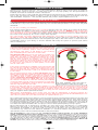
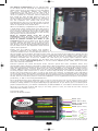
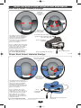
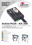
Kit LIW Instructions.qxd
5/6/09
2:03 pm
Page 1
Kit L-IW
Logic Independence WIRELESS
INSTRUCTION MANUAL
and WARRANTY
Kit L-IW includes:
2x
2x
2x
2x
2011 Logic Independence WIRELESS main control hub units
2116 Complete noise cancelling stereo headsets with plug-in boom microphones
2174 Standard 400mm phone leads
2243 Standard 150mm stereo music leads
WIRELESS
HUB
HUB
IMPORTANT NOTE:
PLEASE ASK your supplier to personally check with you that this kit contains ALL the parts listed
above before you leave the shop!
Autocom UK has carefully checked that all of the parts listed above are supplied in this kit at the
time of packing and shipping; however we also train our suppliers to check and confirm with you (in
the shop) that you have all of these listed parts supplied in your kit before leaving the shop. Because
of this thorough triple check quality control method Autocom UK cannot accept any claims for
missing parts once you have left the shop.
This product is intended for sale ONLY from authorised retail premises by trained authorised
Autocom dealers, where your supplier has provided you with high quality hands on demonstration
and advice about the products before you purchase. This product is not to be sold/purchased via
mail order etc or from any dealer who has not/or cannot provide you with high quality face to face
hands on demonstration and after sales service and support.
If this product was supplied to you by mail order, we ask that you please contact
[email protected] or telephone: +44 (0)1926 431249 and let us know who your supplier
was, such that we can ensure that ALL of our customers receive the highest standards of supply and
support that our customers, products and brand deserves.
Please fill in and return the product registration on the inside back cover.
It is very important that you fully read and understand all of
these instructions before installation and use.
This system is designed for domestic motorcycle use only.
Kit LIW Instructions.qxd
5/6/09
2:03 pm
Page 2
CONGRATULATIONS
Thank you for choosing Autocom. Your Logic Independence Wireless hub-to-hub system is designed,
built and fully tested to provide you with many years of very high quality use and performance if
installed and used as described in these instructions.
Please take the time to fully read and understand these instructions before installation and use and feel
free to ask your Autocom dealer for advice, or call our help-line if anything is not perfectly clear and
understandable. Telephone: +44 (0)1926 431249 (UK). Email: [email protected]
SAFETY FIRST
It is very important to properly set up and use these products as designed. Please do not make any
modifications or try to use your system with any non recommended products or in any other way than
described.
Do not cut or modify your helmets.
It is common sense and the law in some countries that the rider of a vehicle be in control at all times,
which includes the ability to hear other road users warnings. As such the RIDER should not have the
music volume so loud as to prevent this. Safety should always be your first priority and is ultimately
the responsibility of the rider. Make sure that the quick release connectors are free to quick release in
the event of an emergency. Do not fix or tape them together.
The rider should only make adjustments while stationary, never while in motion. Always focus your
attention to riding and safety and do not use the system in such a way as to interfere with this. The
added ability to communicate between rider and passenger and/or with other riders on other bikes can
considerably improve your safety, so become familiar with using the system to provide good advice
and/or warnings etc.
front of rider, likely
ed in
to b
end
eu
m
nr
om
eli
ec
le
ab
The two Logic Independence Wireless hubs supplied in Kit
L-IW come ready paired and with their own noise cancelling
8 ohm stereo headsets, plug-in noise cancelling boom
microphones, plus Velcro to aid fitting in some helmets,
plus 2 standard phone and stereo music leads.
No
tr
OVERVIEW
The wireless link between the two hubs is normally very
reliable when used between a rider and passenger on the
same bike and with no obstructions between the hubs.
Ideally each hub should be positioned in a clear line of site
and as close together as possible. The recommended
positioning is with the rider’s hub behind the rider and the
passenger’s hub in front of the passenger or with the hubs
in each user’s side pockets (or belts packs) on the same
side as each other.
RIDER
It should be noted that the reliability of the wireless link will
be reduced if for example the rider’s hub was in front of the
rider (in a tank bag etc) and/or the passenger’s hub is
placed behind the passenger (with your bodies/s between
to two hubs).
ble
PASSENGER
tr
ec
ia
No
The wireless link has a range of up to 10 metres and was
factory paired and fully tested at 5 metres range as part of
our quality control procedure. Normally the system will be
used at less than 1 metre apart and so should be very
reliable. Customers should be aware that the wireless link
can sometimes disconnect (drop out) and if this happens
the hubs are designed to, and will normally automatically
reconnect within seconds, however sometimes you may have
to manually re-establish the wireless link by powering down
and then repowering the two hubs.
om
un
me
be
nde
y to
d beh
l
e
k
i
l
ind passenger,
l
re
For best reliability, keep the hubs as
close together in clear line of sight.
Please note that each hub is only splash resistant; it is not designed to be completely sealed, allowing
it to breathe, which helps to prevent a build-up of condensation that can develop due to internal heat
from the power regulator and main high power amplifiers. Please ensure the hubs are used in a water
resistant pocket or optional suitable belt pack to help prevent excessive water contamination. Please
ask your supplier about optional belt cases.
With proper understanding, some people may feel that the advantages of wireless systems are
outweighed by their disadvantages over wired systems. Each type has benefits and disadvantages over
each other so please ask your Autocom dealer to explain this for you.
The logical mixing and control design not only provides wireless communications between the rider and
passenger hubs, but also allows each hub to interface independently with various other audio devices
such as bike-to-bike radio, GPS, phones, stereo music and/or radar detectors etc, simply by selecting
the optional interfaces to suit your specific needs. It is designed and sold this way to save you cost, as
to include all possible parts/options for every potential variation would not be practical or cost effective.
Your Autocom dealer should be able to help you choose what optional parts you may require.
Each independent hub is designed for portable use using either three AA batteries or rechargeable
batteries (in each hub), or an optional two-part bike power lead. Again none of these power methods
are supplied as standard in the kit so that you can choose and buy only the parts you want. We
recommend only using the best batteries available for extended duration and performance or the
optional bike power lead for unlimited duration and performance.
The front panel on each user’s hub has a master volume control (green) and voice activation
(VOX) sensitivity preset control (purple) so that you can independently preset each user’s volume
and VOX levels on their own hub to suit individual needs (with or without earplugs etc). The front panel
on each user’s hub has a small breakaway section to provide access to the internal Aux 1 connector
(for optional bike-to-bike radio interface lead) plus the user’s headset lead and 3 sockets for Aux 2,
3 and 4 as clearly shown on the label. Aux 5 is for an internal optional plug-in stereo Bluetooth
module (Part 2217) which can connect to suitable phones and/or stereo music devices.
2
Kit LIW Instructions.qxd
5/6/09
2:03 pm
Page 3
The battery compartment (on the opposite side
to the label) can be accessed by depressing the
catch release circle on the battery cover and sliding
the cover downwards. Within the battery
compartment you will notice a red L.E.D. and a
small press button switch next to it. This is only
used for pairing the wireless rider-to-passenger
link, which we have already factory set for you
when purchased as Kit L-IW. Once set, pairing of
the two hubs is automatic each time you connect
the two headsets. The switch and L.E.D. are
provided just in case you ever want to pair your hub
with another hub that has not already been paired,
which is explained in full details later.
While in the battery compartment you will also note
a small white slider switch which sets each hub to
mode A or B. In either mode the rider to passenger
link is always maintained and a bike-to-bike radio
can be connected to either hubs Aux 1 and used by
both persons via the wireless link.
Mode A (switch away from the 9 pin
connector) makes Aux audio inputs 2, 3 and 4
independent to only the hub they are connected to.
Mode B (switch towards the white 9 pin
connector) allows you to share your Aux 2, 3 and
4 audio inputs connected to your hub via the
wireless link with the other person using the other
hub. Please note that all audio transmitted between
the two hubs is mono, but amplified to both left and
right helmet speakers.
Please note the battery positive and negative
orientation markings on the battery tray helps to
ensure the batteries are correctly fitted, however we
have provided reverse polarity protection just in case you incorrectly fit the batteries in which case the
system simply will not work. For longer journeys, in particular when using a bike-to-bike radio, some
customers may prefer to bike power the system which can also power a suitable bike-to-bike radio,
providing mile-after-mile of fuss free reliable use, and saves you carrying spare batteries and/or
chargers, in particular when camping etc. The white 9 pin connector in the battery compartment is for
use with one of the optional bike power, or remote control VOX/PTT power leads, which come with
their own instruction manuals.
Autocom systems are track developed under extreme speed and noise conditions where they
demonstrate highly effective performance. Each part is fully tested before it leaves the factory and set
such that most users will simply power, connect up and use straight out of the box without the need to
make any adjustments, however, apart from the external adjusters for individual headset volume
controls, VOX level preset controls there are also various additional internal adjusters so that you can
set and program each control box to work in various ways allowing for maximum flexibility. Some
people may need a little more time or help to get used to the system, in particular to the importance
of correct microphone and speaker positioning and fine turning, so please be patient and if in any doubt
do not hesitate to ask for help. If your system is not performing as you would expect or as we claim it
should, then the most likely cause is incorrect installation or use, in particular microphone and speaker
positioning, or flat or incorrectly fitted batteries.
These instructions have been designed to try to help you get the most out of your system, but if it does
not exceed your expectations then we want to help. You are welcome to visit our factory at anytime,
Monday to Friday, 09.00 to 17.30 plus Saturdays by appointment. If you cannot get to our factory then
please contact Autocom, your dealer or distributor; details available on our website: www.autocom.co.uk
We hope you like this product and enjoy it for many years to come, as much as we have enjoyed
designing and building it for you.
Tom Beman (MD)
Autocom Products Limited
Aux 2 (GPS)
Aux 1 (Bike-to-bike)
Aux 3 (mobile phone)
Headset lead
Aux 4 (Stereo music)
Vox
control
Harder
Volume
control
Higher
Softer
Lower
When the arrow pointers face upright the
unit is set to the pre-set standard settings.
3
Kit LIW Instructions.qxd
5/6/09
2:03 pm
Page 4
CONNECTIVITY • LOGICAL MIXING AND CONTROL
Aux 1 • designed for Bike-to-Bike
Both rider and passenger can use a bike-to-bike radio connected to either hub via the I-VOX system,
providing easy and safe hands free use, without losing the rider to passenger communications or any
other functions. Incoming bike-to-bike audio (on Aux 1 on either hub) automatically reduces the stereo
audio level on both hubs Aux 4 to 50% to improve speech clarity. When a hubs phone is in use it
disables that hubs bike-to-bike VOX transmit function so that your phone conversations are not
broadcast out to the other bikes, which allows the other bikes to continue with bike-to-bike
communications while you are on the phone. You can optionally bike power your hub which can then
also bike power recommended bike-to-bike radios, plus take advantage of the optional handlebar
remote control, to disable the VOX transmit mode providing rider-to-passenger privacy. You can
transmit bike-to-bike messages at any time by either pressing the press-to-talk (PTT) button, or toggle
back to the normal VOX transmit mode. When the phone is in use and disables the VOX transmit
function, the remote control PTT button lets you over-ride this so that you can transmit to other bikes
even when on the phone.
Aux 2 • designed for Stereo GPS
Incoming stereo audio on your hub Aux 2 is amplified only to your headset and automatically reduces
the stereo music on your hubs Aux 4, by 50% for improved GPS clarity. Note; you can use some phones
via some GPS units, but in most cases you lose the important GPS audio and safety camera warnings
while using the phone through a GPS. This is why we provide separate GPS stereo connectivity and
separate phone connectivity to manage this better for you.
Aux 3 • designed for Stereo Phone
Phones can be connected to each hub using the standard leads* supplied, or via the optional stereo
Bluetooth interface, without losing the rider-to-passenger communications. You can use some phones
via some GPS units but see the note in Aux 2 above.
Incoming phone audio on Aux 3 automatically reduces the stereo music on Aux 4 by 100% and biketo-bike/GPS audio by 50% to improve phone conversation. The VOX transmit mode for bike-to-bike is
also disabled so that your phone conversations are not broadcast out to other bikes.
*Some phones may require a hands free adaptor.
Aux 4 • designed for Stereo Music
Both rider and passenger can independently enjoy their own stereo music using the standard leads
supplied, which let you connect to most typical mp3/iPods etc. Note; these connections can be used for
some stereo phones, record out etc.
Rider and passengers speech, plus bike-to-bike audio automatically reduces the stereo music on both
hubs Aux 4 by 50% to improve communications. Your incoming GPS audio on Aux 2 automatically
reduces your stereo music on Aux 4 by 50% for improved clarity. Incoming phone audio on your Aux
3 automatically cuts your stereo music on Aux 4 by 100% for improved phone conversations.
Optional Stereo Bluetooth Aux 5
The single stereo Bluetooth module lets you connect wirelessly to one or two Bluetooth devices, so long
as one is using hands free profile (such as a mobile phone or GPS, etc) and the other uses advanced
audio profile (A2DP, such as stereo devices, mp3 players, etc).
The Bluetooth module can be set to have the same effects as incoming audio on either Aux 2 or 3.
High Quality and Performance Rider and Passenger Noise Cancelling Headsets
When either person speaks, the I-VOX system automatically turns only their microphone on, reduces
the stereo music and transmits the bike-to-bike radio, for safer hands free use. When you stop speaking
the microphone automatically turns off and the music gently glides back to its normal level. High
quality, robust, water resistant, connectors and leads are custom designed for easy, safe and
comfortable use and quick release in an emergency. Built to last but also easy to service or replace.
Please see notes about using wireless systems on our website: www.autocom.co.uk
GETTING STARTED
Having already read this manual completely and checked any questions with your dealer, you should
now be ready to power one of the hubs and set/test prior to headset installation.
Pre-set the master volume and VOX controls ready for your first test.
Volume Control (Green)
With the master volume control turned
fully anti-clockwise the volume will be
very low.
Turning your master volume control
clockwise turns ALL your hubs audio
inputs plus the speech levels up. Because
the system is capable of being VERY LOUD
for use with earplugs CAUTION should be
used when turning the volume control
clockwise above the mid-way position
unless you are using conventional
earplugs. A good place to start is with the volume control in about its mid position (with the knob
pointer facing the pointer on the label) which should suit most peoples need for use in most helmets
and bikes between 0mph and 120mph, but please note this is with the speakers correctly positioned
and using the microphones loud spot.
4
Kit LIW Instructions.qxd
5/6/09
2:03 pm
Page 5
It is important that you set each users master volume control to suit each users own level of side-tone
and then fine tune the level as required to suit the received speech from the other user. If any other
audio levels (such as bike-to-bike, phone GPS or music etc need to be adjusted it is important that you
adjust each level using the audio devices own volume control. Do not turn the master volume control
up or down to adjust other audio input levels, as doing so may unbalance your desired level of sidetone or that of the other user’s speech level. Once everything is set up and balanced you will normally
only ever use the master volume control/s to suit individual needs or differences between using
earplugs or not.
Voice Activation (VOX) Control (Purple)
VOX is short for “voice activated switching” and gives you several advantages. Apart from turning your
microphone off when you are not speaking, ensuring no noise whatsoever is picked up and amplified to
your ears, the VOX can automatically mute the music or make your transceiver transmit when you
speak, giving you hands free and safer operation.
With the VOX control turned fully anticlockwise the VOX will turn on permanently (as if you are
permanently speaking) causing the microphones to be forced on and any music in Aux 4 to be reduced
to 50%, and if using a bike-to-bike radio it will be forced into constant transmit mode. Turning the VOX
control clockwise sets the VOX and the higher you turn it the more it makes the VOX harder to operate
but also reduces the chance of helmet noise from accidentally turning the system on when you are not
speaking, especially at higher speeds. A good place to start is with the VOX control in its mid position
(with the knob pointer facing the pointer on the label) which should suit most peoples need for use in
most helmets and bikes between 0mph and 120mph.
Power
Remove the battery cover and power the hub using your preferred method. If using 3 AA batteries
please ensure they are new/fully charged and carefully note each batteries positive end must align with
the positive markings in the battery tray. If using the optional bike power lead Remove all the
batteries and connect the 9 pin white plug of the system side of the power lead into the white socket
in the battery compartment. Make sure the bike side of the power lead is correctly connected to the
bikes switched ignition circuit and that the red in-line power connector is plugged firmly together and
that ignition is switched on. You will notice a small breakaway tongue at the bottom edge of the case
which normally aligns with the slot in the battery cover, please carefully break this off to provide an exit
point for the bike power lead. If you know whether you want to use mode A or B you could set this now
while inside the battery compartment before replacing the battery cover.
Please note that if your system produces strange noises it is an indication that the batteries are below
an acceptable level. You may find that when you speak the VOX operates and you hear your own voice
via the side-tone, but when you try to establish the wireless link the system emits an undesirable noise
through the speakers to let you know that it will not link. Installing new/charged batteries will solve this
for you.
If you are not going to use your systems for an extended period, it is recommended that you remove
the batteries from the hubs.
5
Kit LIW Instructions.qxd
5/6/09
2:03 pm
Page 6
FIRST TEST
We strongly recommend that you test your headset out of the helmet (before installation) to
make it easier for you to experience how even small movements in microphone and speaker positioning
can reduce or improve the sound quality and ease of use. With this knowledge you will have a
benchmark to work to during final helmet installation later and be sure you are getting the very best
out of your system. Please do not use earplugs during this first test as they will hide and/or disguise
much of what we are trying to listen for.
Avoid pressure directly to the front and back covers of the microphones as this could cause damage.
The microphone is floating in an acoustically dampening material to help prevent any helmet vibration
being transmitted through the boom to the microphone as part of the noise cancelling measures. To
move or adjust the microphone please hold it by the outer edges or rubber neck, making sure that the
beige side of the fabric sits flat against and central to your lips. Try to avoid the microphone covers
touching the Velcro on the back of the speakers.
Connect the boom microphone to the headset loom, noting the red connectors will only connect
together if aligned the right way round, making sure that it clicks right in. Connect the headsets black
7 pin plug into the hubs black 7 pin headset lead socket, which automatically turns the hubs power on.
MICROPHONE LOUD SPOT POSITIONING AND USE
The microphone has a critical loud-spot which is the point where it produces the maximum energy from
your speech into the system with the least amount of effort. The system has been carefully designed
and tuned around using this loud-spot (as part of its superior noise cancellation design) and so it is very
important that you understand and use this loud-spot correctly.
While holding one of your own speakers over your ear place the beige side of your microphone against
your lips and project your voice positively through it, as if to someone 5 metres (15’) away. Try gently
moving the microphone around (with it still touching your lips) while making a continuous positive tone
noise to find the microphone LOUD SPOT.
You will know when you have found and used the microphone loud spot correctly because your voice
will reliably activate the VOX, and you know when you have reliably activated the VOX because the
system has SIDE-TONE which amplifies your own voice through your own speakers, but only when
activating the VOX, thus providing you with audio confirmation of correct microphone and VOX use.
Remember; if you can hear your own voice amplified through your own speakers then you are operating
the VOX and so you know that others will be hearing what you hear.
If during this test you hear your voice cutting in
and out while trying to speak, don’t worry as
this is quite normal for first time users until you
have practiced getting used to the system.
You must speak into
the beige side of the
microphone
It is a natural reaction when in a quiet
environment to speak quietly; it is also natural
to speak even quieter if you hear your own voice
amplified to your own ears louder than you
normally hear yourself, and this, combined with
not being used to using the microphone loud
spot, is why you may have not operated the VOX
correctly.
If the VOX cuts in and out while speaking it is a
natural reaction to want to turn the VOX level
down to make it easier to use, but if you do this
you may turn the VOX lower than necessary
which could cause it to false activate when riding
at higher speeds, so instead of reducing the VOX
level you must ignore the fact that you can hear
yourself through you own speakers, find and
keep using the microphone loud spot, projecting
your voice positively through it, and if required
reduce the master volume slightly which
reduces your side-tone level and so will help you
to naturally speak louder and make it easier to
operate the VOX. Please practise this for a while
to get used to it. Please also remember that
when riding your bike you will be in far more
noise and so will naturally raise your voice and
find using the VOX much easier.
6
Kit LIW Instructions.qxd
5/6/09
2:03 pm
Page 7
Top Tips (1)
Fine tune and perfect using the microphone loud-spot by listening to the sound of your voice through
the speakers while carefully moving the microphone around until it is at its very loudest point. It can
also help if you pucker your lips to the microphone as if kissing it.
Apart from providing you with audio confirmation of correct microphone and VOX use, side-tone also
helps you to naturally speak at the correct level when in noisy conditions and so also prevents
unnecessary shouting. However it is important not have your master volume control set
unnecessarily higher than needed, because apart from adding to riding fatigue and wasting valuable
battery power, if your side-tone level is set too loud it will make you want to speak much quieter
and so make it more difficult to operate a higher VOX setting, which may be needed for higher speed
use. Turning your master volume level as low as possible will reduced the level of your own sidetone and encouraging you to speak louder and so make operating higher VOX levels much easier,
and save battery power.
If you are now comfortable with finding and using the microphone loud spot and operating the VOX
reliably without turning it lower than we have suggested, we want you to now experience the
importance of speaker positioning.
SPEAKER POSITIONING
Ideally you want to play one of your most favourite pieces of music through the system that has rich
sounds and plenty of bass, being something you can identify with later when testing the helmet
installation.
Try to generate as much background noise as you possibly can by revving a bike engine or using a loud
TV, hi-fi system or perhaps a noisy vacuum cleaner etc, as this ambient noise will simulate helmet noise
as if riding.
With the system powered and the headset connected, plug the 3 pole end of the music lead supplied in the
kit into your music devices headset socket, and also connect the 4 pole end into Aux 4 socket of your hub.
Top Tips (2)
Make sure that you plug your music lead into the music systems headset socket and not the line out
socket, or the volume control may not work.
Adjust the music devices volume control to about half way and then press play. Listen to the music level
and adjust if required before holding the speakers over your ears.
Note that the speakers are
slightly off-set in their housings
so try to align the centre of the
speakers directly with centre of
your ear-holes (with the wire
coming out towards the back of
your head). Apply light pressure
to the back of the speakers and
you should now hear the music
clearly with the minimum amount
of background noise being heard.
You will notice that moving the
speakers just a small amount away
from your ears, or out of alignment
(up, down, backwards or forwards)
can easily half the volume and
reduce the sound quality, in
particular the bass response, and
let in considerable external
background noise which will spoil
the full potential of sound quality
and performance, especially at
higher speeds when the helmet
noise becomes far more powerful
and/or when using earplugs.
Centre of
speaker
Centre of
ear hole
Note that wire
normally comes out
towards back
Centre of ear hole
Avoid speaker
near top of ear
Centre of ear
hole
Centre of
When you have readjusted the
speaker
speaker positioning comfortably
but firmly over your ears so that
the music quality is at its very
best and you can hear the least
amount of background noise
coming through, you have found the best possible speaker position and so you now know what
to aim for when fine tuning the speaker positioning after helmet installation.
If you now hold the microphone to your lips and project your voice positively through the loud spot, the
VOX turns your microphone on while at the same time automatically reduces the music level to improve
communications. When you stop speaking the microphones automatically switches off and the music
gently returns to its original level. Practice this a few times to become familiar with it, and show your
passenger what you have discovered.
Top Tips (3)
It’s sometimes a bit tricky holding three parts with only two hands so try pressing one ear to your
shoulder with the speaker in between, leaving your hands free for the other speaker and boom
microphone, or get someone to assist with holding the microphone for you.
7
Kit LIW Instructions.qxd
5/6/09
2:03 pm
Page 8
CONNECTING THE TWO WIRELESS HUBS
Now that you know how to set up and use one of the hubs/headsets properly, it is time to set up the
other hub/headset (the same as you have with the first one) and then start communicating between
the two hubs via the wireless link.
Place the two hubs side by side, labels down and with both battery covers removed (with good batteries
correctly installed, or bike powered). Connect each headset (within 10 seconds) to power the hubs and
establish the wireless link. You will know when the wireless link is established when both hubs red
L.E.D.’s are constantly lit (you may notice that about every 4 seconds the lit L.E.D./s blinks off just for
a split second, this is normal).
If someone is available to assist, get them to copy you and hold their microphone/speaker in position
and speak positively to each other via the wireless link. You will notice that when you speak and operate
your VOX that your speech is transmitted, via the wireless link and you both hear your voice as your
side-tone provides you with important audio confirmation that you have communicated properly. The
system is DUPLEX and so you can both speak at the same time, so practice this for a while to get used
to it.
While testing you may notice a slight echo if you can hear both hubs headset speakers. Please do not
worry about this as it will not be noticeable when the headsets are installed into your helmets, or while
riding.
Rider-to-Passenger Mode
At the time of factory testing and the two hubs were first linked, one became the MASTER HUB (marked
M on the test label within the battery compartment) and the other became the SLAVE HUB (marked S
on the test label in the battery compartment). It is important to connect both hubs headsets within 10
seconds of each other, in order to establish the wireless link for rider to passenger use. After this time,
if your hub has not found and connected with the other hub, it will stop searching as part of its battery
saving design. If this happens and you want to re-establish the wireless rider to passenger link you will
have to disconnect and then reconnect both headsets within 10 seconds of each other.
Rider-to-Rider Mode
If you want to split the two hubs between two bikes and use them independently with optional bike-tobike radios, you can simply power up the master hub first (for about 30 seconds) BEFORE turning on
the slave hub. This will prevent the wireless link establishing, which not only save battery power but
also ensures that you are only communicating via the bike-to-bike radios, and not also via the wireless
link when close together which would otherwise cause an undesirable echo effect.
Please remember to disconnect each hubs headset in order to turn each hub off when not being used,
as leaving the headsets connected while not in use wastes battery power.
HEADSET INSTALLATION
Because Autocom systems work so much better than other systems, it is easy for people to think its
working great even when it’s not set up and used properly and only giving you perhaps 30% of what
is really has to offer. This is why we recommend that you to test the headset out of the helmet with
some music, so that after installation you can hear if it sounds right and adjust as required. Using music
is the best way of hearing this, even if you do not intend using music in future.
The plug-in boom microphone/s supplied in the kit is our most universal boom designed to fit most full
face, flip front and open face helmets, but please note; most open face and enduro/moto-cross style
helmets, including flip-front helmets if you want to ride with it open, will require the optional open
face conversion kit (Part 2156) to prevent excessive direct wind blast getting to the microphone. The
headset is not designed to work with 1⁄2 helmets (chip style) which normally require a much longer boom
and perhaps some additional padding to mount the speakers over your ears. Replacement consumable
microphone coverings (Part 2166) are available from your dealer. The optional long boom microphone
(Part 2075) is similar to our standard boom microphone but is 35mm (13⁄8”) longer and is ideal for larger
open face helmets.
There are far too many different helmet types available to be able to fully describe every possible
installation here, and one must also consider that each year various helmet designs change, so these
instructions are designed as a basic guide only. Please see your local Autocom dealer or visit our website
www.autocom.co.uk for more detailed specific helmet installations. Most authorised Autocom dealers
are trained and experienced with helmet fitting.
Please note; helmets that have straps that go directly over your ears may not lend themselves for a
good headset installation, as the speakers have to sit either on top or behind the straps, which can
make them uncomfortable or out of position which will reduce the sound quality. This is beyond our
control and if our speakers do not fit, nor will any others. It is a good idea to remember this next time
you choose a helmet. You can overcome this problem by using optional in-ear speaker plugs that can
replace the standard over the ear type speakers. Our optional Part 2091 allows you to use most types
of in-ear speaker plugs with your system.
Some helmets may not lend themselves to be installed as we have suggested and so may require
alternative methods. Please take plenty of time to carefully consider all these basic principles, together
with the installation diagrams and your own helmet design to see if you can establish any similarities
that may help you with installation. If you are unsure about any of the above then please contact your
supplier or Autocom for help and advice.
DO NOT CUT YOUR HELMET!
8
Kit LIW Instructions.qxd
5/6/09
2:03 pm
Page 9
Top Tips (4)
When installing the headset into the helmet place the helmet on a soft towel etc, so as to help stop
it sliding about and/or getting scratched. If you fit one helmet first, you can then test the installation
for sound quality/level and then when you think you have the speakers correctly positioned you can
compare it to the other headset that has not been installed. When you are completely happy with
the first helmet installation you can then install the second headset into your other helmet. If ever
passing an approved Autocom dealer you can ask them if you can compare your headset installation
with their ear-defender demo/test headsets in the shop. It is a good idea to do this at least once
every six months just to check your speakers haven’t move over time through putting the helmet
on and off.
Put the helmet on and try to work out exactly where the centre of each ear hole is relative to the straps
or any seams etc in the lining, and also while doing this try to find and mark the exact location of the
centre of your lips inside the chin pad with the helmet sat in its natural position. When you have
established these positions within the helmet you are then ready to start the headset installation/s.
Top Tips (5)
You may notice that most peoples ear holes are between 1” and 11⁄2” below the top of their ears, and
that most peoples top of their ears are about in-line with their eyebrows. If you look at someone’s
face through the helmets visor area, you can reference their eyebrow position and assist them with
working out the approximate position below this for their ear holes. If they can then also feel and
then reference the approximate horizontal position of their ear holes relative to the straps etc, it will
provide a good starting point for speaker positioning.
There are two main types of typical full face helmet designs, one is a one part chin and cheek
pad design, per the illustration shown on the top of page 10, the other and more popular type is a three
part chin/cheek pad design per the illustration shown at the bottom of page 10. Most full face helmets
do not have the cheek pads glued in and are just a compression fit, which makes them much easier to
remove (although some are quite tight).
9
Kit LIW Instructions.qxd
5/6/09
2:03 pm
Page 10
BASIC PRINCIPLE HOW HELMETS ARE ASSEMBLED
One Part Inner Helmet Design
View from
underside
of one part type
helmet
Remove
straps and
lift out complete
The fabric is either taped or
elasticated over the polystyrene
and so it is easy to install the
speakers behind the lining.
Note that the wire should come
out of the speaker towards the
back of the helmet.
Before replacing the cheek pad,
tape the boom and the headset
loom to the outer side of the
polystyrene. When the cheek
pad is fitted back into the
helmet, it will secure the boom
and loom inside the helmet.
Do not modify the helmet.
Peel back tape and lining, slide
speaker inside pushing it right
up to the strap hole
Boom microphone
assembly
Tape to hold in place
Return assembly as removed
Three Part Inner Helmet Design
View from underside
of three part type
helmet
Remove
straps and lift out
each cheek pad
individually
The fabric is either taped or
elasticated over the polystyrene
and so it is easy to install the
speakers behind the lining.
Note that the wire should come
out of the speaker towards the
back of the helmet.
Before replacing the cheek
pads, tape the boom and the
headset loom to the outer shell
or the back side of the cheek
pad. When the cheek pad is
fitted back into the helmet, it
will secure the boom and loom
inside the helmet.
Do not modify the helmet.
Boom
microphone
assembly
Return assembly as removed
10
Tape between cheek pad and
outer shell
Kit LIW Instructions.qxd
5/6/09
2:03 pm
Page 11
Microphone
Decide which side of the helmet you would prefer the
lead and plug to hang from (normally the left side)
and then release and remove that side’s cheek pad
so as to allow you fit the boom microphone and main
speaker harness behind it, with the boom coming up
from behind the check pad and up into the visor area
and then bent down (from between the outer shell
and back of the cheek pad) in front of your mouth,
per the illustrations. Remember you must speak
into the beige side of the microphone. If required
tape the boom and also the main harness down lead
to the inside of the outer shell of the helmet using
some of the Velcro supplied in the kit which is usually
very good for this purpose so long as where you are applying it is completely clean and dry.
Top Tips (6)
Avoid crossing any wires with another or with the boom as this will create a higher than necessary
spot which may make it difficult to replace the cheek pad. If your helmet has an air vent in chin-bar
(in front of your mouth) it is a good idea to cover and seal this from the inside of the chin-bar so
that the wind is not able to blast directly onto the back of the microphone. This also helps to force
more of the airflow up into the visor area which can often make demisting the visor more effective
for you. With the microphone positioned close to your mouth, you may notice that it just clips your
nose when putting the helmet on and off. You can avoid this by learning a technique of slightly
twisting the helmet so that the boom clears your nose while putting the helmet on or off.
While the cheek pad is removed you can see if the fabric is taped, glued or preferably elasticated behind it.
Speakers
Most helmets have ear pockets (indentations) designed into the lining to let
your ears fold back after they are folded over while putting the helmet on.
Sometimes the fabric covering these pockets is glued back to the
polystyrene cheek pad, forming a visible pocket. Other times the fabric is
just stretched over the foam pocket and is not glued back.
If the helmet has deep pockets and the fabric is glued back you may
need to fit some padding behind the speakers (like our optional foam speaker
pads Part 2159 which are about 6mm or 1⁄4” and/or Part 2160 which are about
12mm or 1⁄2”). These foam speaker pads have Velcro fitted so that you can fix
the speakers to them. Always start without padding and with the speakers set
low then test for comfort/sound quality, then pack out and adjust up to the
correct positioning over your ear hole thus avoiding having the speaker too
high or tight where it may cause excessive pressure to the top of your ear.
If the fabric is not glued back forming a visible pocket then while it is
easier to just Velcro the speakers on top of the loose fabric (which can
sometimes work quite well in some helmets) is far more likely to cause your
ears to fold over when putting the helmet on, so most people prefer a more
professional installation where the speakers are set behind the fabric but on
top of the foam/polystyrene behind. If you have time and can install the speakers behind the
fabric, it makes for a much more professional semi-permanent fitment which is normally
much more comfortable and this is how we would normally try to install the headset/s for you if you
brought them to us.
In order to be able to place the speakers behind the fabric you normally need to remove the cheek pads
from the helmet to reveal the back where the fabric is glued, taped or preferably just elasticated over
the polystyrene. Carefully peel the fabric back enough to slide the speakers into place (normally about
level or just below the level of the hole for the strap and just behind the strap). Try to copy the
illustrations on the front cover and/or page 10. Again it is important to start of with the speakers set
deliberately lower to help with maximum comfort and avoid pinching the top part of your ears, and then
adjust them upwards as required to obtain the best sound level and quality. If you have to un-glue or
tape the fabric, masking tape is often used to stick this back down.
Please see the illustration on page 7 and note that by angling the speakers as shown it helps to ensure
even pressure between the speakers and your ears, thus improving both comfort and sound quality.
The speaker wire normally exits the speaker towards the back of the helmet.
Top Tips (7)
If your cheek pad has a plastic tongue to hold it in place, be careful not to break this off when removing
or replacing the cheek pads, and also be careful not to trap or cut the speaker wire/s with it when
replacing the cheek pads. When you have installed the headset you can use the back of a toothbrush
handle to make a great tool for carefully pushing any wires up into the lining and around the back of
the neck draft excluder. You may find it is better to fix the speakers with Velcro so as to help avoid
them slipping up inside the helmet which can happen over time due to movement when putting the
helmet on. For the first time putting the helmet on after installation it is often beneficial to use
something like a silk balaclava to help prevent your ears being folded over while putting the helmet on
and off until you have fine tuned the speaker positioning for maximum comfort and performance. If
for example your right ear is folded over after putting the helmet on you should immediately use your
right hand to pull the right hand strap so that you can get your left hand fingers up into the right hand
side of the helmet to flick your right ear back straight etc. while doing this you may also be able to feel
the speaker in relation to your ear and if possible try to move the speaker for a better fit.
11
Kit LIW Instructions.qxd
5/6/09
2:03 pm
Page 12
TESTING THE INSTALLATION AND FINE TUNING
With some music playing through the speakers try to focus on one speaker at a time and move the
helmet up, down, back and forwards and also side to side to listen for improvements or loss of sound
level and quality.
If moving the helmet forwards improves the sound level or quality for that speaker it means your
speaker is set too far back, so readjust it forwards.
If moving the helmet up improves sound level or quality it means the speaker is set to low, so adjust
each speaker upwards accordingly until you are happy that you have the best possible speaker
positioning.
If you push the side of the helmet towards your head and notice improved sound it means you need to
pack the speakers out on some foam so that they are nearer and covering your ear hole.
Ensure the sound is equally balanced to both ears, if it is slightly louder or has more bass in one ear it
means the other speaker is out of alignment or needs more packing out until the sound from both
speakers is equal.
It may take a little extra time now to get each speaker correctly positioned but it will pay huge dividends
in sound quality and high speed performance, especially if you intend using high attenuation earplugs.
Note you may need to readjust your speakers for more comfort during your first ride out and until they
have settled in, or if they should move over time.
SETTING THE VOX CONTROL
Start with the VOX control set to the centre position per the illustration and go for a ride to see if the
helmet noise (at speed) false triggers the VOX.
Top Tips (8)
Remember to use the microphone loud spot. It is a good idea to set the VOX about 20mph (32kmh)
faster than you would normally travel so that head winds do not cause it to false trigger. If your
helmet has chin bar vents that allow air to blow straight through onto or near the back of the
microphone area then this should be blocked off from the inside of the chin bar such that (1) you
do not get direct wind blast to the back of the microphone/s and (2) because in most cases this also
helps to get more air up into the visor area, which can often help with de-misting problems. A
wind/draft excluder is sometimes fitted under the chin bar of some helmets and this can help reduce
excessive wind noise at higher speeds thus allowing for a lower VOX setting.
After checking the above if the VOX is still false activating slightly turn the VOX control knob clockwise,
say about 1⁄8 of a turn at a time, and try it again, and keep doing this until you have set the VOX such
that helmet noise does not accidentally turn it on at the typical speeds you ride.
Incorrect VOX setting will cause the music to keep muting and/or bike-to-bike transceiver to keep
transmitting when not speaking and this would prevent you from being able to receive and this is why
a correctly set VOX is very important and why you must find and use the microphone LOUD SPOT rather
than reduce the VOX level to compensate.
You may notice that the passenger needs a slightly higher VOX setting than the rider. This is normal
because the passenger is more helmet noise, plus gets turbulence off the riders shoulders and so
required a slightly higher VOX setting.
USING BIKE-TO-BIKE TRANSCEIVERS
Although it is usually straightforward to connect up and start using bike-to-bike radios via our VOX
systems, we strongly recommend that your first test and get used to using both radios (hand held) per
their own instructions (ensuring that the radios are not in VOX mode) and become familiar with them.
This is important because most typical radios used are half duplex and so you have to get used to taking
it in turns speaking to each other, plus allow for any short delays that the radios may have between
when you first transmit and start speaking, to when the other radio receives and accepts the
transmission, and then allows your transmitted speech to be amplified to the speaker after first
accepting the anti-interference tone code. Using radio discipline (as you would hear professionals use
them) greatly improves both the reliability and ease of use.
This test is also important to prove the radios are set up and able to communicate properly to one
another which helps eliminate any frustrating problems that are sometimes caused if the radios are not
set up on the same channels or codes etc.
You should always press the press to talk (PTT) button a split second before speaking and always say
“OVER” before releasing the PTT button at the end of your communications to let the other person know
when you have finished speaking, so that they know they can then speak back. Before the other person
speaks back they should always allow a second or so after you have said OVER before pressing their
PTT button, and wait a split second before speaking, etc.
When you are practiced and comfortable using the two hand-held radios with some radio discipline, you
are then ready to connect one of the radios to the system (using the appropriate interface lead to suit)
keeping the other radio as a hand-held for now, while you become practiced in using our VOX in place
of the radios PTT. Please do not try to connect both radios to the systems until you have practiced with
one connected and the other as a hand held first.
12
Kit LIW Instructions.qxd
5/6/09
2:03 pm
Page 13
Connecting one of the bike-to-bike radio’s to your system
Remove the battery cover and batteries from one of your hubs and then remove the two Pozi-Drive
screws from the hubs small back cover, allowing it to be removed. NOTE you should lightly press down
on the battery tray while carefully lifting the small back cover off. This then reveals the Aux 1 (CONN
1) white 9 pin connector on the main circuit board.
Carefully break off the blanking tab from inside the small back cover (the outer of the two, which
previously covered one of the slots in the front panel) and then orientate the interface leads white
connector so that the red wire is towards the centre of the hub, before carefully aligning the pins and
pressing the connectors together.
Carefully position the interface lead around the outside of the nearby black fixing pillar and push the
interface lead into the front panel slot (the outer one) so that the strain relief sleeving is inside the front
panel.
Before replacing the small back cover, push the wires down so that they will not be trapped between
the black pillar and small back cover when it is replaced. With the small back cover in place, check
alignment around the front panel etc before replacing the two Pozi-Drive screws. You can then replace
the hubs batteries and battery cover.
Connect the interface leads plug to the radio, making sure it is fully plugged all the way in (fit the
retaining clamp if one is provided with the radio) and turn the radio on to about 50% volume.
When you speak into your systems microphone and activate the hubs VOX (your own side-tone
confirms this for you) the other radio should receive your speech and they can then adjust their hand
held radios volume to a suitable level. Please use this setting as a guide to set the volume on the radio
connected to your hub, BEFORE getting the other person to transmit back to you using their hand held
radio, and then when they transmit back to you, you can readjust your radios volume if required.
Your will notice two important things happening which you have to understand and get used to
working with in order to perfect using the system.
1) When you speak and activate your VOX it instantly switches on (as confirmed by your own sidetone) and the VOX simultaneously switches your bike-to-bike radio from standby or receive mode,
into transmit mode. (If your radio has a transmit L.E.D. or indicator you will notice this activates
almost instantly when you speak and operate your VOX).
There is unfortunately a short delay between when this happens and when your speech is actually
heard through the other radios speaker. This is because after receiving your transmission, the other
radio has to switch between battery saving/standby mode into receive mode and then check and except
the anti-interference tone code before allowing the sound to be amplified through the speaker. The
result of this short delay is that when you say something like “left at the lights” it may be heard as
“at the lights” to which the reply is “what about at the lights”, which is heard as “about at the
lights”, I think you get the message (which is that you won’t) so to get over this you must get used
to always using a KEY WORD, (like you will hear professionals such as the police use) for example;
“OK… turn left at the lights, OVER!” this key word and a short pause will ensure that your intended
radio transmissions are heard in full, likewise by saying the word OVER the other person then knows
you have ended your transmission and after a second or two your VOX will then switch your radio from
transmit back to receive.
2) When you stop speaking there is a (deliberately designed) short delay before your VOX switches
the radio back from transmit mode to receive mode. This delay is the best compromise between;
staying on as long as possible to help prevent any pauses during normal conversations causing
the system to think you have stopped speaking and returning the radio back to receive mode
halfway through your conversations; and; as short as possible so that when you do actually stop
speaking, the delay time for your radio to stop transmitting and return to receive mode is minimal,
so that the other bike/s can then transmit back to you as quickly as possible.
Aux 1
Always power off your systems before connecting or disconnecting auxiliary leads.
If you bike power your hub, you will need isolation audio interface leads if using bike powered audio
devices.
13
Kit LIW Instructions.qxd
5/6/09
2:03 pm
Page 14
TROUBLESHOOTING GUIDE
The WIRELESS LINK does not link, or keeps dropping out.
G Check that the batteries are fresh in both hubs and that the hubs are close together with no
obstructions between them. Disconnect BOTH headsets and reconnect them within 10 seconds and
the hubs should automatically establish the wireless link.
Speech volume is too quiet.
G Only adjust the riders or passengers volume controls to increase volume levels after you have first
checked you have correctly positioned the speakers and are talking into the beige side of the
microphone and using the microphone loud spot, if required raise your voice.
Phone/GPS/radar/transceiver or music volume is too quiet.
G Ensure speakers are correctly positioned (remember speakers may slip up over time).
G Adjust volume level on each audio device such as phone/GPS etc to suit.
G Only adjust the master volume control/s to increase the overall volume levels.
Music mutes 50% even when I don’t speak.
G Increase the VOX level by turning the control clockwise.
Phone will not auto answer.
G Ensure your phone has this facility.
G Ensure that you have connected the adaptor block properly (if needed).
G Check that the phone is set to auto-answer whilst in headset mode (hands free).
G Try connecting the adaptor to the phone followed by plugging the lead in.
Problems with bike-to-bike radios
G Ensure that you take turns to speak and that you leave 2 seconds between transmissions. See page
12 for hints and tips.
G Ensure both transceivers are on the same channel and sub-tone.
G Check that the connections on the radio are secure.
G Adjust volume level on each transceiver.
G Ensure the microphone is positioned correctly and that you are using the loud spot and operating
the VOX see page 6.
G If using a press-to-talk (PTT) check the switch position is set to VOX mode.
G Ensure that the PTT switch position is central when powering up the system.
Interference whilst the engine is running.
G If you are bike powering your system and any audio devices connected by wire, check that you are
using isolated interface leads. Unplug all accessories and see if the noise is still audible. If the noise
has gone, plug one lead in at a time until the noise returns. You now know which lead is picking up
the noise. It will either need re-routing or it is an incorrect lead.
If you need more help or advice please contact your local Autocom supplier.
STANDARD 12 MONTHS MANUFACTURERS WARRANTY
If your supplier has not given advice or demonstration on how to set up or use our products, please
check with them before sending any goods back for warranty.
All Autocom products are warranted for a period of 12 months from the date of original purchase, to
the original purchaser, from an authorised Autocom retailer. This warranty covers faulty materials or
workmanship, subject to the goods being used only as stated, and only for the purpose as described in
the instruction manuals.
No manufacturer's warranty applies to the goods where they are used for any other purpose or in any
other way than is explained in the instructions. Nor where the goods have been subjected to misuse,
neglect or accidental damage, or used with any other vendor’s products, including incorrect mechanical
or electrical installation, or where the goods have been repaired, modified or altered, without the
manufacturer’s written authorisation.
The manufacturer's warranty is limited to the goods being returned pre paid to the manufacturer's
factory, with the original packaging and the original proof of purchase date. The goods must be intact
for our examination.
This warranty does not cover any consumable items such as batteries, replaceable hygiene foam
coverings for speakers and microphones, or any other items that are described within the instruction
manuals as being a consumable.
Where goods are accepted by the manufacturer, under the terms of the warranty, they will be repaired
free of charge or replaced (at the option of the manufacturer). Where the goods are returned as faulty
and are found not to be, a charge will be payable to cover costs of inspection, testing, packing and
return postage. For details of authorised repair centers available in various countries please ask your
dealer or visit www.autocom.co.uk
The manufacturer's warranty does not affect your statutory rights.
FOR ANY FURTHER HELP OR INFORMATION PLEASE CONTACT YOUR SUPPLIER OR
Autocom Products Limited
Unit 4, Tachbrook Link, Tachbrook Park Drive, Warwick, CV34 6RH. England
Telephone: +44 (0)1926 431249 (10 lines) - Fax: +44 (0)1926 431250
Email: [email protected] - Website: www.autocom.co.uk
14
Kit LIW Instructions.qxd
5/6/09
2:03 pm
Page 15
PRODUCT REGISTRATION
Dear customer, PLEASE REGISTER YOUR NEW PRODUCTS within 30 days
of purchase and receive priority service, simply by returning this
completed form to:
Autocom Products Limited
Unit 4, Tachbrook Link, Tachbrook Park Drive, Warwick, CV34 6RH. England.
or
fill in a product registration form on-line at; www.autocom.co.uk
CUSTOMER DETAILS
Original purchase date: .................................................................................................
Name: ............................................................................................................................
Address: .........................................................................................................................
......................................................................................................................................
......................................................................................................................................
Post code/Zip code: ............................................Country:.................................................
Telephone: ......................................................................................................................
Email: ............................................................................................................................
Please confirm; I do / do not wish to receive additional/updated information about your
products, and/or other new products which may be of interest to you.
Privacy
There is no legal obligation on your part to provide the personal information requested, however
such information allows us to maintain a record about the products and how customers are
supplied and supported, which can help improve our standards and speed up any returns/service
works. The information collected will be used for marketing purposes by Autocom and our
authorised distributors only. We may contact you either in relation to the products you already
have or other Autocom products which may be of interest to you.
SUPPLIERS DETAILS (please stamp if available)
Original purchase date: .................................................................................................
Dealers Name: .................................................................................................................
Address: .........................................................................................................................
......................................................................................................................................
......................................................................................................................................
Post code/Zip code: ............................................Country:.................................................
Telephone: ......................................................................................................................
Email: ............................................................................................................................
Member of staff who sold the products (optional) .................................................................
Product serial number
(each visable in each hubs battery compartment under the battery holder)
Kit L-IW ...........................................................M.........................................................S
15
Kit LIW Instructions.qxd
5/6/09
2:03 pm
Page 16
Unit 4, Tachbrook Link,
Tachbrook Park Drive, Warwick CV34 6RH. England
Tel: +44 (0)1926 431249 • Fax: +44 (0)1926 431250
Email: [email protected]
Website: www.autocom.co.uk