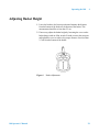
1
100 Automated
Disintegration
Apparatus
Operator’s Manual
Agilent Technologies
Notices
© Agilent Technologies, Inc. 2014
Warranty
No part of this manual may be reproduced
in any form or by any means (including
electronic storage and retrieval or translation into a foreign language) without prior
agreement and written consent from Agilent Technologies, Inc. as governed by
United States and international copyright
laws.
The material contained in this document is provided “as is,” and is
subject to being changed, without
notice, in future editions. Further,
to the maximum extent permitted
by applicable law, Agilent disclaims
all warranties, either express or
implied, with regard to this manual
and any information contained
herein, including but not limited to
the implied warranties of merchantability and fitness for a particular purpose. Agilent shall not be
liable for errors or for incidental or
consequential damages in connection with the furnishing, use, or
performance of this document or of
any information contained herein.
Should Agilent and the user have a
separate written agreement with
warranty terms covering the material in this document that conflict
with these terms, the warranty
terms in the separate agreement
shall control.
Manual Part Number
70-9066
Edition
Rev C, March 2014
Printed in USA
Agilent Technologies, Inc.
3501 Stevens Creek Blvd.
Santa Clara, CA 95052 USA
Technology Licenses
The hardware and/or software described in
this document are furnished under a
license and may be used or copied only in
accordance with the terms of such license.
Restricted Rights Legend
U.S. Government Restricted Rights. Software and technical data rights granted to
the federal government include only those
rights customarily provided to end user
customers. Agilent provides this customary commercial license in Software and
technical data pursuant to FAR 12.211
(Technical Data) and 12.212 (Computer
Software) and, for the Department of
Defense, DFARS 252.227-7015 (Technical Data - Commercial Items) and DFARS
227.7202-3 (Rights in Commercial Computer Software or Computer Software
Documentation).
Safety Notices
CAUTION
A CAUTION notice denotes a
hazard. It calls attention to an
operating procedure, practice, or
the like that, if not correctly performed or adhered to, could result
in damage to the product or loss
of important data. Do not proceed
beyond a CAUTION notice until
the indicated conditions are fully
understood and met.
WA RNING
A WARNING notice denotes a
hazard. It calls attention to an
operating procedure, practice,
or the like that, if not correctly
performed or adhered to, could
result in personal injury or
death. Do not proceed beyond a
WARNING notice until the
indicated conditions are fully
understood and met.
100 Operator’s Manual
Contents
Figures
1
Safety
7
9
Electrical Hazards 9
Warning
11
Caution
11
Note
11
Information Symbols
2
Introduction
12
13
Conventions Used in this Manual
Serial Number Format
3
Setting Up the 100
14
15
17
Unpacking Your 100 18
Environmental Requirements for Installation
Setting up the Water Bath
20
Initial Power Up 21
Electrical Connections
21
Installing the Temperature Probe
Water Bath Status LEDs
22
23
Setting the Date / Time Clock
24
Mounting Baskets and Filling Beakers
Draining the Water Bath
100 Operator’s Manual
19
25
25
3
Contents
Hidden Key Functions
4
Operating the 100
26
27
Setting Water Bath Temperature
28
Setting Print Frequency for the Report Center Printer
Adjusting Basket Height
29
Placing Dosage Units in the Baskets
Selecting Operating Mode
Single-basket Operation
Multi-basket Operation
Three-Basket Operation
28
30
30
30
31
34
Printer Operation During Manual or Program Operation
(Optional) 34
5
Troubleshooting and Maintenance
35
Preventive Maintenance
36
Weekly Maintenance 36
Monthly Maintenance 36
Every Six Months Maintenance
37
Yearly Maintenance 37
Disintegration Basket Care 37
Water Bath / Acrylic Care 38
Visual Checks 40
Water Bath Temperature Probe Accuracy Test
41
Report Center Impact Printer
43
Installing the Cartridge Ribbon 43
Replacing the Paper Roll
44
Toggling Your Printer Online 45
Printer Self Test
46
Printer Configuration 47
4
100 Operator’s Manual
Contents
Troubleshooting
49
Obtaining Warranty and Other Services
Index
100 Operator’s Manual
51
53
5
Contents
This page was intentionally left blank, except for this message.
6
100 Operator’s Manual
Figures
Figure 1.
Figure 2.
Figure 3.
Figure 4.
100 Operator’s Manual
Water Bath Connections
100 Rear Panel 21
100 Keypad
23
Basket Adjustment 29
20
7
Figures
This page was intentionally left blank, except for this message.
8
100 Operator’s Manual
100 Automated Disintegration Apparatus
Operator’s Manual
1
Safety
Electrical Hazards
9
The Agilent 100 has been designed and tested so that when used
properly you have an accurate, fast, flexible, and safe instrument.
If the equipment is used in a manner not specified by the manufacturer,
the protection provided by the equipment may be impaired.
The Agilent 100 is operated in conjunction with equipment that uses
aqueous liquids. Unskilled, improper, or careless use of this instrument
can create shock hazards, fire hazards, or other hazards which can cause
death, serious injury to personnel, or severe damage to equipment and
property.
Information on safety practices is provided with your instrument and
operation manuals. Before using your instrument or accessories, you
must thoroughly read these safety practices.
Observe all relevant safety practices at all times.
Electrical Hazards
The Agilent 100 contains electrical circuits, devices, and components
operating at dangerous voltages. Contact with these circuits, devices,
and components can cause death, serious injury, or painful electric
shock.
Panels or covers that are retained by fasteners which require the use of a
tool for removal may be opened only by Agilent-trained,
Agilent-qualified, or Agilent-authorized service engineers. Consult the
manuals or product labels supplied with the 100 to determine which
parts are operator-accessible.
Agilent Technologies
9
1
Safety
Application of the wrong supply voltage, connection of the instrument
to an incorrectly wired supply outlet, or lack of proper electrical
grounding can create a fire hazard or a potentially serious shock hazard
and could seriously damage the instrument and any attached ancillary
equipment.
Always use a three-wire outlet with ground connection which is
adequately rated for the load. The installation must comply with local,
state, and federal safety regulations.
Do not connect the instrument to the main power supply until you have
made sure that the operating voltage is correctly set for the main power
supply in the specific outlet in your laboratory to which the equipment
will be connected.
10
100 Operator’s Manual
Safety
1
Warning
WA RNING
A ‘Warning’ message appears in the manual when failure to observe
instructions or precautions could result in death or injury.
Read all warnings and cautions carefully and observe them at all times.
Caution
CAUTION
A ‘Caution’ message appears in the manual when failure to observe
instructions could result in damage to equipment (Agilent supplied and /
or other associated equipment).
Note
NOT E
A ‘Note’ appears in the manual to give advice or information.
100 Operator’s Manual
11
1
Safety
Information Symbols
I
0
Switches main power on
Switches main power off
Indicates single-phase alternating current
Indicates the product complies with the
requirements of one or more European Union
(EU) directives.
Indicates specific equipment meets standards of
safety. These products are safe for use in the
workplace for North America.
Indicates that this product must not be disposed
of as unsorted municipal waste.
All Agilent products that are subject to the
WEEE directive shipped after August 13, 2005
are compliant with the WEEE marking
requirements. Such products are marked with the
“crossed out wheelie bin” WEEE symbol in
accordance with European Standard EN 50419.
For more information on collection, reuse, and
recycling systems, please contact your
local/regional waste administration, your local
distributor, or Agilent.
Indicates the product complies with regulatory
compliance requirements of New Zealand and
Australia.
12
100 Operator’s Manual
100 Automated Disintegration Apparatus
Operator’s Manual
2
Introduction
Conventions Used in this Manual
Serial Number Format 15
14
Agilent Technologies
13
2
Introduction
The 100 is designed to provide versatility and reliability, while meeting
all current USP testing requirements. Its three basket positions can be
programmed to dip together or independently, allowing up to three
different tests to be run at the same time. In addition to the standard
six-tube USP-approved basket rack, a variety of optional basket racks
are available for large and bolus tablets. The 100 is used for
disintegration testing in accordance with current USP requirements. The
optional built-in Report Center Printer provides hard-copy
documentation of the instrument operation for the highest degree of
confidence.
The 100 is available in two models: single basket and three basket. The
three-basket apparatus is fully programmable by simply entering the
time duration of the test. The baskets automatically lift from the beaker
at the end of the test in the pass / fail mode. The three-basket model has
individual digital time displays for each basket. The water bath
temperature is displayed continuously on the front panel. Both models
include accessories.
CAUTION
Panels or covers that are retained by fasteners which require the use
of a tool for removal may be opened only by Agilent-trained,
Agilent-qualified, or Agilent-authorized service engineers.
Conventions Used in this Manual
• Items you are asked to press are in bold. For example, “press H on
the keypad”.
14
100 Operator’s Manual
Introduction
2
Serial Number Format
The serial number contains 10 characters and follows this syntax:
CC1234xxxx
Syntax Code
Meaning
Description
CC
Country of origin
2 alpha characters matching the required trade designation for
the country of origin
12
Year of manufacture
‘09’ for 2009, ‘10’ for 2010, etc.
34
Week of manufacture
‘01’ for week 1 to ‘52’ for week 52
100 Operator’s Manual
15
2
Introduction
This page was intentionally left blank, except for this messsage.
16
100 Operator’s Manual
100 Automated Disintegration Apparatus
Operator’s Manual
3
Setting Up the 100
Unpacking Your 100 18
Setting up the Water Bath 20
Initial Power Up 21
Installing the Temperature Probe 22
Water Bath Status LEDs 23
Setting the Date / Time Clock 24
Mounting Baskets and Filling Beakers
Draining the Water Bath 25
Hidden Key Functions 26
25
Agilent Technologies
17
3
Setting Up the 100
Unpacking Your 100
1 Open each carton and check the contents for damage which may
have occurred during shipping. Shipping damage rarely occurs, but if
it does contact both the carrier who delivered the instruments and the
Dissolution Systems Service Department. Though claims for damage
should be filed with the carrier, we can help you file a claim.
2 Carefully remove the 100 from its shipping carton. Hold the unit
firmly to prevent it from dropping.
WA RNING
Hold the unit only by the base. Do not hold by the reciprocating
shafts to avoid damage.
3 Check for items which may have come loose during shipping. Be
sure to remove all parts before discarding or storing the packaging.
4 Place the unit on a clean, dry, level section of the bench top or table.
At least four inches of space should be open for the rear panel power
connections and for access to the rear panel power switch.
WA RNING
18
The electrical connection at the back of the apparatus is the
primary disconnect for the instrument. The apparatus should be
positioned to allow accessibility to the power cords for easy
disconnection.
100 Operator’s Manual
Setting Up the 100
3
Environmental Requirements for Installation
• Humidity: max relative humidity 80% for temperatures up to 31 ºC
decreasing linearly to 50% relative humidity at 40ºC
• Indoor use only
• Pollution Degree: 2
• Installation Category: II
• Altitude: 2000m
• Temperature: 5 ºC to 40 ºC
• Power: 115 V/60 Hz, 230 V/50 Hz, 10 A
Main supply voltage fluctuations are not to exceed ± 10% of the
nominal supply voltage
100 Operator’s Manual
19
3
Setting Up the 100
Setting up the Water Bath
1 Ensure the 100 is not plugged in.
2 Place the water bath on the 100 with the lower quick-connect fitting
positioned on the left side of the apparatus. Use the locator holes on
the water bath and the locator pins on the 100 to ensure proper
placement.
3 Locate the two tubes with quick-connect fittings and insert them into
the appropriate quick-connect fittings on the 100 water bath (see
Figure 1, “Water Bath Connections,” below).
Figure 1
Water Bath Connections
4 Ensure the cover is in place on the water bath with the small hole
toward the front. Ensure the disintegration beakers are not in place in
the cover.
5 Fill the water bath through any one of the three beaker holes in the
cover.
NOT E
Initially fill the water bath no higher than 2.5 inches (6.4 cm) from the
top, to allow for displacement by the beakers when they are inserted.
6 Check the water bath and all connecting tubing for leaks. When
satisfied that no leaks are present, proceed to “Installing the
Temperature Probe” on page 22.
20
100 Operator’s Manual
Setting Up the 100
3
Initial Power Up
Electrical Connections
WA RNING
Before plugging the 100 into any power outlet, ensure the
instrument is configured for the voltage provided. Check the
serial number tag on the rear panel to confirm the voltage
requirement.
The electrical connection at the back of the apparatus is the
primary disconnect for the instrument.
See Figure 2, “100 Rear Panel,” to complete the steps that follow.
Figure 2
100 Rear Panel
1 Ensure the power is off.
2 Connect the power cord between the AC power connector and an AC
power receptacle of the appropriate voltage.
3 Turn on the 100. The three position screens and the temperature
screen on the front panel illuminates immediately. You will hear the
circulator working as it begins to pump the bath water through the
system. Bubbles may appear at the water bath inlet as air is expelled
100 Operator’s Manual
21
3
Setting Up the 100
from the system.
NOT E
Check for leaks. Allow the circulator to run for five minutes, then check
the bath, tubing, connectors and the bench area immediately
surrounding the apparatus. If any water leaks are seen, turn off the
power immediately and remove the power cord. Locate and fix the
source of the leak before proceeding.
4 Place the disintegration beaker(s) through the holes in the top cover
of the water bath.
5 As the water circulates, there may be a slight drop in the water bath
level as the internal tubing fills. Wait until the beakers are in place
before adding additional water as required to bring the level back to
within no more than 2.5 inches of the top of the water bath. Replace
the cover, if removed.
Installing the Temperature Probe
The 100 is shipped with a factory-installed temperature probe inside the
heater /circulator tank and an external probe to be placed directly in the
water bath. Both probes are necessary and the temperature readings
must remain within 5 °C of each other or the 100 will not operate. If
either probe is not functioning or not installed, the alarm sounds and the
keypad is inactive.
NOT E
No installation or positioning is necessary for the internal temperature
probe.
To install the external temperature probe, complete the following steps:
1 Plug the temperature probe into the jack labelled TEMP. PROBE on
the rear panel.
2 Insert the metal tip of the probe into the small hole in the water bath
cover.
3 Ensure the small hole and temperature probe are toward the front of
the water bath.
22
100 Operator’s Manual
Setting Up the 100
3
4 Press INT/EXT to view the temperature readings for each probe.
When the external probe reading displays, the Ext Temp Probe LED
illuminates.
Water Bath Status LEDs
water bath
status LEDs
Figure 3
100 Keypad
The Heater On LED flashes to indicate heater activity. When the heater
is on continuously, as will occur when the water bath is cold, the LED
remains illuminated. As the target temperature is approached, the LED
flashes indicating the heater is cycling on and off.
The Over Temp LED illuminates
• if the temperature of the water of the water bath exceeds 65 °C.
Check for obstructions and low water if this condition occurs. The
over temp condition clears automatically when the temperature
cools below 55 °C. Press CLEAR to reset if the temperature is
between 55 and 65 °C.
• if the external temperature probe is not in the water bath or is not
connected.
• if the temperature probe readings are more than 5 °C higher than
the set temperature.
100 Operator’s Manual
23
3
Setting Up the 100
The Ext Temp Probe LED illuminates when the external temperature
probe reading displays in the temperature screen. Otherwise the internal
probe reading displays.
NOT E
If the external temperature probe is not connected, the temperature
display reads 4.4. This is normal and changes as soon as the probe is
installed.
The Printer On LED illuminates when the Report Center Printer has
been enabled.
Setting the Date / Time Clock
If you are using the built-in Report Center Printer to document the test
conditions, you must set the correct date and time. This information
displays on all printouts.
To set the date and time, complete the following steps:
1 Press SET CLOCK. The Position 3 screen flashes the date.
2 If the date is correct, press ENTER. Otherwise, enter the correct date
in mm/dd/yy format and press ENTER. The time flashes.
3 If the time is correct, press ENTER. Otherwise, enter the correct
time in 24-hour format and press ENTER.
24
100 Operator’s Manual
Setting Up the 100
3
Mounting Baskets and Filling Beakers
1 Ensure the water bath cover is in place on the water bath.
2 Place one, two, or three 1000 mL USP disintegration beakers through
the water bath cover holes so they are suspended in the water bath.
3 Hold the beaker(s) down and pour 900 mL of the required
disintegration medium in each beaker. When full, the beakers sit
securely in the cover and do not float.
4 Place one, two, or three basket racks onto the horizontal basket
supports.
5 Verify the water level in the water bath is above the media level of all
beakers. If not, either add additional water or drain excess water until
the proper working level is reached.
Draining the Water Bath
WA RNING
Disconnect the 100 from the AC power receptacle before
draining the tank.
1 Disengage the quick-connect fitting on the left side of the tank and
attach the supplied drain hose.
2 Open the drain valve and drain the water bath into an appropriate
receptacle or sink.
3 Use a clean paper towel or damp cloth to wipe out the water bath and
remove any remaining water from the bottom of the tank.
100 Operator’s Manual
25
3
Setting Up the 100
Hidden Key Functions
The following seldom-used operations can be performed by pressing
and holding CLEAR and then pressing the number on the keypad and
releasing both keys at the same time. Refer to Figure 3, “100 Keypad,” .
Table 1
26
Hidden Key Functions
Key Sequence
Function
CLEAR > 0
Use this key sequence to set the communication port identification numbers. Enter the
identification number and press ENTER.
CLEAR > 2
Use this key sequence to enable or disable alarm function.
CLEAR > 5
Use this key sequence to toggle between 1 and 2 decimal places for the temperature
display. Two decimal places is used to calibrate the temperature.
CLEAR > 8
Use this key sequence to select the baud rate. This key combination toggles among 1200,
2400, 4800, and 9600. When the correct baud rate displays, press ENTER.
100 Operator’s Manual
100 Automated Disintegration Apparatus
Operator’s Manual
4
Operating the 100
Setting Water Bath Temperature 28
Setting Print Frequency for the Report Center Printer 28
Adjusting Basket Height 29
Placing Dosage Units in the Baskets 30
Selecting Operating Mode 30
Printer Operation During Manual or Program Operation (Optional)
Agilent Technologies
34
27
4
Operating the 100
Setting Water Bath Temperature
To set the water bath temperature, press SET TEMP. Enter the desired
water bath temperature and press ENTER.
NOT E
It may be necessary to set the water bath temperature up to 0.5 °C higher
than the desired temperature of the medium in the beakers to
compensate for heat loss through the walls of the beakers.
Setting Print Frequency for the Report Center Printer
If your 100 is equipped with a Report Center Printer and you want an
automatic periodic printout of test conditions, enable the built-in Report
Center Printer and indicate the desired automatic print interval.
To enable the printer, press PRINT FREQ. Enter the desired auto-print
interval in mmm format up to 255 minutes and press ENTER.
To disable the printer, enter an auto-print frequency of 0 (zero) and press
ENTER.
28
100 Operator’s Manual
Operating the 100
4
Adjusting Basket Height
1 Lower the basket to the lowest position and measure the distance
from the bottom of the beaker to the bottom of the basket. This
measurement should be no less than 2.5 cm.
2 If necessary, adjust the basket height by loosening the screw on the
basket hanger with an Allen wrench. Extend or retract the two parts
and tighten the screw to achieve the proper distance of not less than
2.5 cm from the bottom of the beaker.
Figure 4
100 Operator’s Manual
Basket Adjustment
29
4
Operating the 100
Placing Dosage Units in the Baskets
Place one dosage unit in each of the six tubes of the basket. USP fluted
disks may be added where specified in the individual monograph.
Selecting Operating Mode
You can select single-basket, multi-basket, or three-basket operation.
NOT E
The Position 3 screen is the display screen for all programming
regardless of which position or parameter you are programming.
Single-basket Operation
In single-basket mode, the operation of each basket is set independent of
the others. To start a single basket:
1 Press RUN # (where # is the basket number you want to run). The
current test time for that position, if any, flashes. For example, the
following display indicates that the basket in the selected position is
currently programmed to dip for 10 minutes:
POSITION 3
001000
2 To accept the current test length, press ENTER. The basket lowers
and begins dipping, lifting automatically at the end of the
programmed time period.
To enter a different dip time value, enter the new value in hhmmss
format and press ENTER to start the dip cycle.
3 To stop the dip cycle of a basket before the end of the programmed
time, press STOP # (where # is the basket number you want to stop).
30
100 Operator’s Manual
Operating the 100
4
The basket stops dipping and lifts from the beaker immediately.
NOT E
Press STOP to immediately stop all baskets.
Multi-basket Operation
There are two benefits of multi-basket mode:
• You can program any combination of baskets to start and stop at
exactly the same time. This feature allows the 100 to function as a
conventional two- or three-basket apparatus.
• You can program the 100 to drop the baskets at staggered times
and to remove them at the same time. This feature is useful when
running different products with different test lengths
simultaneously without returning to the apparatus at different
times to view the end of each test.
For example, you can position baskets 1 and 3 to start and finish
their dip cycles at exactly the same time while Position 2 remains
idle, or baskets 1 and 2 start and finish while Position 3 remains
idle. Alternatively, you can have basket 3 start automatically 5
minutes after basket 1, with a test time 5 minutes less than that for
basket 1. This causes both baskets to finish at the same time while
Position 2 remains idle.
The screen under Position 3 acts as the display screen for programming
the 100. Create a programming sequence as follows:
1 Press SET PROG. In the display, the numeral 1 flashes, alternating
with the previously programmed test length for that position in
hhmmss format. For example, you may see the following alternating
displays:
POSITION 3
1
100 Operator’s Manual
POSITION 3
003000
31
4
Operating the 100
The example on page 31 indicates the previously programmed test
length for Position 1 was 30 minutes.
• To accept the current test length, press ENTER.
• To change it, enter the new value in hhmmss format and press
ENTER.
• To disable Position 1, enter 000000 for the test length and press
ENTER.
2 In the display, the numeral 2 flashes, alternating with the previously
programmed delay time for Position 2 in hhmmss format. The delay
time is the amount of time between the start of the program and the
start of dipping for Position 2. For example, you may see the
following alternating displays:
POSITION 3
POSITION 3
2
000500
The above example indicates the previously programmed delay time for
Position 2 was 5 minutes.
• To accept the current delay time, press ENTER.
• To change it, enter the new value in hhmmss and press ENTER.
• If no delay is desired, enter 000000 and press ENTER.
NOT E
There is no delay time for Position 1.
3 In the display, the numeral 2 flashes again, this time alternating with
the previously programmed test length for Position 2. For example,
you may see the following alternating displays:
POSITION 3
2
32
POSITION 3
004000
100 Operator’s Manual
Operating the 100
4
The example on page 32 indicates the previously programmed test
length for Position 2 was 40 minutes.
• To accept the current test length, press ENTER.
• To change it, enter the new value in hhmmss and press ENTER.
• To disable Position 2, enter 000000 and press ENTER.
4 In the display, the numeral 3 flashes, alternating with the previously
programmed delay time for Position 3 in hhmmss format. The delay
time is the amount of time between the start of the program and the
start of dipping for Position 3. For example, you may see the
following alternating displays:
POSITION 3
POSITION 3
3
001000
The above example indicates the previously programmed delay time for
Position 3 was 10 minutes.
• To accept the current delay time, press ENTER.
• To change it, enter the new value in hhmmss and press ENTER.
• If no delay is desired, enter 000000 and press ENTER.
5 In the display, the numeral 3 flashes again, this time alternating with
the previously programmed test length for Position 3. For example,
you may see the following alternating displays:
POSITION 3
POSITION 3
3
005000
The above example indicates the previously programmed test length for
Position 3 was 50 minutes.
• To accept the current test length, press ENTER.
• To change it, enter the new value in hhmmss and press ENTER.
• To disable Position 3, enter 000000 and press ENTER.
100 Operator’s Manual
33
4
Operating the 100
6 Press RUN PROG. The programmed sequence displays in the
Position 3 screen. If correct, press ENTER. The program begins.
To stop any individual basket during multi-basket operation, press
STOP # (where # is the basket number you want to stop). To stop all
baskets at the same time, press STOP in the lower right corner of the
keypad.
NOT E
When an individual basket is stopped and the other baskets are dipping,
the individual basket can only be restarted in the independent
single-basket mode. It cannot be restarted as part of the running
program.
Three-Basket Operation
To run all three baskets together, starting and stopping at the same times,
complete the following steps:
1 Press RUN MANUAL. The previously set test length (if any) for
three-basket operation flashes in the Position 3 screen.
2 Press ENTER to accept the displayed values or enter a new test
length in hhmmss format and press ENTER. All three baskets lower
and begin dipping. The baskets stop simultaneously, lifting
automatically at the end of the programmed time period.
NOT E
Press STOP to stop all three baskets at any time during the test.
Printer Operation During Manual or Program Operation
(Optional)
If your 100 is equipped with the optional Report Center Printer, you can
generate a printout of the instrument status at any time by pressing
PRINT. This does not affect automatic printing as set by the PRINT
FREQ function.
34
100 Operator’s Manual
100 Automated Disintegration Apparatus
Operator’s Manual
5
Troubleshooting and Maintenance
Preventive Maintenance 36
Water Bath Temperature Probe Accuracy Test 41
Report Center Impact Printer 43
Troubleshooting 49
Agilent Technologies
35
5
Troubleshooting and Maintenance
Preventive Maintenance
WA RNING
The apparatus contains electrical circuits, devices, and
components operating at dangerous voltages. Contact with these
circuits, devices, and components can cause death, serious
injury, or painful electric shock.
Preventive maintenance intervals may vary depending on frequency of
instrument usage.
Weekly Maintenance
See “Disintegration Basket Care” on page 37 and “Water Bath / Acrylic
Care” on page 38 as applicable for additional information on proper
maintenance of your equipment.
• Ensure media is removed and the system is wiped with a clean,
damp cloth. Inspect the water bath and circulator tubing for algae,
other material and cracks / damage. If algae is present, change the
bath water and add algaecide.
• If any stainless steel parts show signs of surface discoloration,
lightly wipe the surface with a soft cloth or nonabrasive pad to
remove it.
Monthly Maintenance
See “Water Bath / Acrylic Care” on page 38 as applicable for additional
information on proper maintenance of your equipment.
• Ensure media is removed and the system is wiped with a clean,
damp cloth.
• Lightly spray Lube1/ WD-40™ onto the shafts and run the
machine for a few minutes.
• Change the bath water and add algaecide.
36
100 Operator’s Manual
Troubleshooting and Maintenance
5
Every Six Months Maintenance
See “Water Bath / Acrylic Care” on page 38 as applicable for additional
information on proper maintenance of your equipment.
• Ensure media is removed and the system is wiped with a clean,
damp cloth.
• Lightly spray Lube1/ WD-40™ onto the shafts and run the
machine for a few minutes.
• Change the bath water and add algaecide.
• Inspect the tubing for algae, foreign material, and cracks /
damage.
Yearly Maintenance
See “Water Bath / Acrylic Care” on page 38 as applicable for additional
information on proper maintenance of your equipment.
• Ensure media is removed and the system is wiped with a clean,
damp cloth.
• Lightly spray Lube1/ WD-40™ onto the shafts and run the
machine for a few minutes.
• Change the bath water and add algaecide.
• Inspect the tubing for algae, foreign material, and cracks /
damage.
• Inspect the security of wires and wiring harnesses.
• Inspect the drive motor—ensure no leaking of oil has occurred.
Disintegration Basket Care
• All of our disintegration baskets are fabricated entirely of
commercial grade acrylic, stainless steel, and glass. When using
them with corrosive materials such as hydrochloric acid or media
containing salts, be sure to rinse them thoroughly with deionized
water immediately after each use, and dry thoroughly with a soft
towel or cloth.
100 Operator’s Manual
37
5
Troubleshooting and Maintenance
• Do not clean with abrasive cleansers or cloths. Use deionized
water whenever possible. If you must use a cleanser or solvent, be
sure that it is as mild as possible, non-abrasive, and fully
compatible with acrylic before use. If in doubt, call the service
department for advice before proceeding.
• Do not use window-cleaning sprays, kitchen scouring
compounds, or solvents such as acetone, gasoline, benzene,
alcohol, carbon tetrachloride, or lacquer thinner. These can
scratch the material’s surface and / or weaken it causing small
surface cracks called “crazing”.
• Our recommendations include but are not limited to the
following:
• Hot water:< 150 °F
• Vinegar (5% Glacial Acetic Acid)
• Ethyl alcohol: maximum 10%
• Isopropyl alcohol: maximum 25%
• Please store disintegration baskets properly between uses. Do not
simply place disintegration baskets in a drawer. They will be
subject to nicks, chips, and scratches as they bump against each
other. Place them back into the original shipping containers or
other appropriate containers between uses. This will prevent them
from coming into contact with each other or anything else in the
storage area.
Water Bath / Acrylic Care
CAUTION
Do not use cleaning compounds containing ammonia or abrasive
cleaners on your water bath.
The water bath supplied with the 100 Disintegration Apparatus should
be maintenance free except for an occasional cleaning. If you use a
water bath algaecide or clear bath product, ensure it is compatible with
PETG and acrylic. The flow paths in the heater / circulator are primarily
38
100 Operator’s Manual
Troubleshooting and Maintenance
5
stainless steel and should tolerate most clear bath formulations. Check
with the product manufacturer to be sure the product is safe for your
water bath.
• All of our water baths are fabricated entirely of commercial grade
acrylic. When using them with corrosive materials such as
hydrochloric acid or media containing salts, be sure to rinse them
thoroughly with deionized water immediately after each use, and
dry thoroughly with a soft towel or cloth.
• Do not clean with abrasive cleansers or cloths. Use deionized
water whenever possible. If you must use a cleanser or solvent, be
sure that it is as mild as possible, non-abrasive, and fully
compatible with PETG and acrylic before use. If in doubt, call the
service department for advice before proceeding.
• Do not use ammonia, window-cleaning sprays, kitchen scouring
compounds, or solvents such as acetone, gasoline, benzene,
alcohol, carbon tetrachloride, or lacquer thinner. These can
scratch the material’s surface and / or weaken it causing small
surface cracks called “crazing”.
• Our recommendations include but are not limited to the
following:
• Hot water:< 150 °F
• Vinegar (5% Glacial Acetic Acid)
• Ethyl alcohol: maximum 10%
• Isopropyl alcohol: maximum 25%
Repairing Leaking Fittings
Complete these steps if any of your water bath fittings are leaking:
1 Turn off the heater / circulator and drain the water bath completely.
2 Remove the leaky bulkhead fitting.
3 Remove the elbow fitting from the bulkhead fitting.
4 Inspect the bulkhead fitting gaskets for damage and replace them as
necessary.
5 Remove the old PTFE tape from all male fittings. Inspect the threads
for damage and replace the fitting as necessary.
6 Apply new PTFE tape to the male fitting threads.
100 Operator’s Manual
39
5
Troubleshooting and Maintenance
7 Reinstall and tighten the bulkhead fitting on the water bath.
8 Reinstall and tighten the elbow fitting to the bulkhead fitting.
9 Fill the water bath and turn on the heater / circulator.
10 Inspect the fitting for leaks. If the fitting still leaks, contact the
Dissolution Systems Service Department.
Visual Checks
CAUTION
Panels or covers that are retained by fasteners which require the use
of a tool for removal may be opened only by Agilent-trained,
Agilent-qualified, or Agilent-authorized service engineers.
1 Turn off power to the instrument and remove the power cord.
2 Remove the six screws located on the right side of the instrument and
remove the side cover.
3 Inspect the drive belt for unusual wear, fraying, and tension.
4 Check the spindle motor brushes for wear every three months.
5 Replace the side cover.
6 Replace the Phillips head screws.
7 Reconnect the power cord and turn on the instrument.
40
100 Operator’s Manual
Troubleshooting and Maintenance
5
Water Bath Temperature Probe Accuracy Test
The temperature probe can be tested using a high quality voltmeter
capable of at least four digit resolution and a known-temperature bath.
Both the voltmeter and the bath temperature must be traceable to a
known reference standard such as NIST.
1 Place the probe into a known-temperature water bath and allow
several minutes for the probe to equilibrate.
2 The resistance is measured by attaching the leads of the voltmeter to
the top and shank of the 1/4 inch phone plug.
3 Refer to the following table to find the resistance value of the probe
at the bath temperature. Temperatures between the values listed may
be interpolated.
4 Probes are interchangeable and manufactured with a tolerance of
± 0.2 °C. Probes found to be outside the tolerance of ± 0.2 °C should
be replaced.
Table 2
Probe Resistance Values
Temp.
Centigrade
Resistance
Ohms
Temp.
Centigrade
Resistance
Ohms
Temp.
Centigrade
Resistance
Ohms
-5.0
9530
24.0
2354
53.0
724.50
-4.0
9046
25.0
2252
54.0
697.90
-3.0
8586
26.0
2156
55.0
672.50
-2.0
8151
27.0
2064
56.0
648.10
-1.0
7741
28.0
1977
57.0
624.80
0.0
7355
29.0
1894
58.0
602.40
1.0
6989
30.0
1815
59.0
580.90
2.0
6644
31.0
1739
60.0
560.30
3.0
6319
32.0
1667
61.0
540.50
4.0
6011
33.0
1599
62.0
521.50
5.0
5719
34.0
1533
63.0
503.30
6.0
5444
35.0
1471
64.0
485.80
100 Operator’s Manual
41
5
Troubleshooting and Maintenance
Table 2
42
Probe Resistance Values
Temp.
Centigrade
Resistance
Ohms
Temp.
Centigrade
Resistance
Ohms
Temp.
Centigrade
Resistance
Ohms
7.0
5183
36.0
1412
65.0
469.00
8.0
4937
37.0
1355
66.0
452.90
9.0
4703
38.0
1301
67.0
437.40
10.0
4482
39.0
1249
68.0
422.50
11.0
4273
40.0
1200
69.0
408.20
12.0
4074
41.0
1152
70.0
394.50
13.0
3886
42.0
1107
71.0
381.20
14.0
3708
43.0
1064
72.0
368.50
15.0
3539
44.0
1023
73.0
356.20
16.0
3378
45.0
983.80
74.0
344.50
17.0
3226
46.0
946.20
75.0
333.10
18.0
3081
47.0
910.20
76.0
322.30
19.0
2944
48.0
875.80
77.0
311.80
20.0
2814
49.0
842.80
78.0
301.70
21.0
2690
50.0
811.30
79.0
292.00
22.0
2572
51.0
781.10
80.0
282.70
23.0
2460
52.0
752.20
100 Operator’s Manual
Troubleshooting and Maintenance
5
Report Center Impact Printer
The following is helpful information for using your impact printer.
Installing the Cartridge Ribbon
If the printer is used infrequently, the print impression sometimes
becomes weak because the ribbon dries out. If the printed material is
difficult to read and you suspect this is the cause of the problem,
advance to a new section of the ribbon by pressing the printer toggle
switch to the Paper feed position. If the printing is still faint, replace the
cartridge.
To install the cartridge:
1 Toggle the printer off line by pressing the printer toggle switch to the
OnLine / Off Line position. When the printer is off line, the Ready
LED does not illuminate.
2 Four small grooves are embossed on the printer cover. Gently push
on these grooves to tilt the cover. When the printer cover is tilted up,
you can lift it off completely.
3 Push down on the right side of the ribbon cartridge (marked PUSH)
and remove the old cartridge.
4 Install the new cartridge. If there is already paper in the printer, hold
the cartridge between your thumb and index finger, slide it over the
paper and into the printer compartment. Ensure the paper is between
the ribbon cartridge and the ink ribbon. Ensure the ink cartridge is
inserted firmly to prevent weak or irregular printing. The cartridge
must be properly seated and aligned for the best printing.
5 Turn the cartridge knob (marked by an arrow) clockwise to stretch
the ribbon taut.
6 Replace the cover.
7 Toggle the printer online by pressing the printer toggle switch to the
OnLine / Off Line position. The Ready LED illuminates.
8 Replace the paper if necessary.
100 Operator’s Manual
43
5
Troubleshooting and Maintenance
If you get ribbon ink on the printer’s plastic cover, remove it
immediately. Once dried, it is difficult to remove.
Replacing the Paper Roll
1 Toggle the printer off line by pressing the printer toggle switch to the
OnLine / Off Line position. When the printer is off line, the Ready
LED does not illuminate.
2 Grasp the paper roll cover firmly by the grooves on the side and the
front edge. Pull outward to remove the cover.
3 Press the printer toggle switch to Paper feed to advance the paper
approximately one inch beyond the paper cutter.
4 Using scissors, cut the paper feeding to the printer and remove the
paper roll.
5 Pull the remaining paper through the printer mechanism. Pull the
paper from the front (paper cutter side). Pulling the paper out of the
back of the printer will damage the print mechanism.
6 Unroll several inches of paper on the new roll.
7 If it is jagged, cut a straight edge on the paper roll to facilitate the
entry of the paper into the printer.
8 Slide the paper through the slot connecting the paper compartment
and the printer compartment. You can slide it in approximately 1/4
inch before it stops.
9 While holding the paper in place, press the printer toggle switch to
the Paper feed position and hold until approximately one inch of
paper has emerged from the top of the printer.
CAUTION
Ensure the roll of paper feeds squarely. If it does not, the paper can
jam and possibly damage the printer mechanism.
10 Release the printer toggle switch.
11 Turn the paper roll to take up any slack in the paper feeding to the
printer.
12 Place the paper roll into the paper compartment.
44
100 Operator’s Manual
Troubleshooting and Maintenance
5
13 Replace the paper roll cover. If the cover is difficult to remove or
replace, the left and right edges can be trimmed or shaved with a
utility knife allowing the cover to slide easier.
14 Toggle the printer online by pressing the printer toggle switch to the
OnLine / Off Line position. The Ready LED illuminates.
Toggling Your Printer Online
Complete these steps to toggle your printer online:
1 Toggle the printer online by pressing the printer toggle switch to the
OnLine / Off Line position. When the printer is off line, the Ready
LED does not illuminate.
2 Release the switch and it returns to the center position. The Ready
LED illuminates and a READY message prints if the PRINT READY
command has not been turned off. See “Printer Configuration” on
page 47 for instructions on turning on and off the PRINT READY
command. When you first turn on the instrument, it prints a READY
message to assure you that the built-in microprocessor is operating
properly.
When you turn off the printer, wait at least three seconds before turning
it on again.
100 Operator’s Manual
45
5
Troubleshooting and Maintenance
Printer Self Test
You can test the print head and ribbon only after inserting paper. Do not
attempt to print without paper. Follow these steps to perform a printer
self test:
1 Turn off the 100.
2 Press and hold the printer toggle switch in the Paper feed position.
3 Turn on the 100.
4 Hold the printer toggle switch until printing begins. The printer
prints a list of the current configuration settings and performs a
continuous print test.
5 Press the printer toggle switch to the OnLine / Off Line position to
stop the printing operation.
6 The printer is ready to resume normal operation.
46
100 Operator’s Manual
Troubleshooting and Maintenance
5
Printer Configuration
NOT E
The printer configuration is set by the factory. This procedure should be
performed only if the printer displays erroneous characters. Contact the
Dissolution Systems Service Department for assistance, if necessary.
1 Turn off the 100.
2 Press and hold the printer toggle switch in the OnLine / Off Line
position while turning on the instrument. Hold the printer toggle
switch in the OnLine / Off Line position for six seconds after the
instrument is turned on, then release the switch.
3 The printer should print: *** SETUP MENU *** and CONFIGURE...
[NEXT/OK]. If this message does not print, repeat steps 1 through 3.
4 The printer toggle switch is used to complete the configuration.
Pressing the left side of the printer toggle switch selects NEXT to
advance to the next menu item. Pressing the right side of the printer
toggle switch selects OK to accept what is stated on this line of the
menu item. Each time the switch is pressed, another part of the menu
prints. Allow the printer to finish printing before pressing the switch
again. See the table of commands on the following page.
NOT E
100 Operator’s Manual
The printout is easier to read if the printer cover is removed.
47
5
Troubleshooting and Maintenance
Table 3
Printer Commands
*** SETUP MENU***
CONFIGURE
[NEXT/OK]
Press NEXT to avoid configuration
CUSTOM
[NEXT/OK]
Press OK to enter custom mode
***CUSTOM MENU***
PRINT CUSTOM SETUP [NEXT/OK]
Press NEXT
AUTO SEQ = NO
[NEXT/OK]
Press OK
ZERO = Ø
[NEXT/OK]
Press OK
POUND SIGN = #
[NEXT/OK]
Press OK
_(UNDERSCORE)
[NEXT/OK]
Press OK
ONLINE/OFFLINE = YES [NEXT/OK]
Press OK
EXT CH SET = NO
Press OK
[NEXT/OK]
PRINT READY = YES
[NEXT/OK]
Press NEXT
PRINT READY = NO
[NEXT/OK]
Press OK
READY...
5
48
100 Operator’s Manual
Troubleshooting and Maintenance
5
Troubleshooting
Table 4
Troubleshooting
Symptom
Probable Cause
Possible Solution
The displays do not illuminate.
The unit is not connected to an
AC power source.
Connect the 100 to a power outlet.
The fuse is blown.
Replace the fuse.
Dipping does not start
immediately at an individual
position.
Delay is programmed for the
position in question.
Reprogram the delay.
The optional Report Center
Printer does not function.
The printer is disabled.
Program a print frequency other than 000.
The Report Center Printer
functions, but nothing appears on
paper.
The ribbon is exhausted.
Replace the ribbon cartridge.
The water does not circulate.
The tubing or pump is clogged.
Remove the back panel and inspect the tubing
from the water bath to the pump. Remove the
tubing from the pump and inspect the inlet of
the pump for debris.
The pump is faulty.
Contact the Dissolution Systems Service
Department for assistance.
The water bath level is too low.
Add water to the water bath.
The OverTemp light remains on.
Turn on the printer. The Ready LED
illuminates.
Air is trapped in the tank or lines. Attempt to prime the system by raising and
lowering the front and rear of the instrument.
The temperature probe may be in
the wrong position or faulty.
Inspect the position and condition of the
water bath temperature probe. Ensure the
probe is plugged into the 100. Check the
position of the probe within the water bath
and ensure it is fully submerged.
The temperature probe should only be used to
measure the water bath temperature. Faulty
readings occur if you use the probe in any
other manner.
100 Operator’s Manual
49
5
Troubleshooting and Maintenance
Table 4
Troubleshooting
Symptom
Probable Cause
Operation is noisy.
Air is trapped in the tank or lines. Attempt to prime the system by raising and
lowering the front and rear of the instrument.
The water circulates but does not
heat.
Possible Solution
The pump or motor is faulty.
Inspect the electrical connection from the
pump / motor to the main PCB for damage or
excessive wear. Replace the pump if
necessary. Contact the Dissolution Systems
Service Department for assistance.
Plumbing connections are in the
wrong configuration.
Ensure the lower bulkhead fitting tube on the
water bath is connected to the pump inlet.
The temperature setting is
incorrect.
Ensure that the correct set temperature has
been input.
The heater relay is defective.
Contact the Agilent Service Department for
assistance. See “Obtaining Warranty and
Other Services” on page 51.
The heater elements are degraded
or faulty.
For 115 V, the resistance is between 10 and 15
ohms. For 230 V, the resistance is between 48
and 52 ohms.
Contact the Agilent Service Department for
assistance. See “Obtaining Warranty and
Other Services” on page 51
The temperature is not stable or is
incorrect.
50
The main PCB is faulty.
Contact the Agilent Service Department for
assistance. See “Obtaining Warranty and
Other Services” on page 51
The thermistor is faulty.
Exchange the water bath temperature probe
with a known good probe if one is available.
If one is not available, see “Water Bath
Temperature Probe Accuracy Test” on
page 41.
Instrument requires calibration.
Contact the Agilent Service Department for
assistance. See “Obtaining Warranty and
Other Services” on page 51
100 Operator’s Manual
Troubleshooting and Maintenance
5
Obtaining Warranty and Other Services
To place a service order (warranty or other services), please contact your
local Customer Care Center. Contact information can be found at
www.agilent.com under your country using the Contact Us link. Place
your service request using the displayed phone number or E-mail
address.
100 Operator’s Manual
51
5
Troubleshooting and Maintenance
This page was intentionally left blank, except for this message.
52
100 Operator’s Manual
Index
Numerics
L
Single-basket Operation, 30
3-BASKET OPERATION, 34
Leaking Fittings, repairing, 39
T
A
M
Acrylic care, 38
Monthly Maintenance, 36
Mounting Baskets, 25
Multi-Basket Operation, 31
Temperature Probe, 22
Temperature Probe Accuracy
Test, 41
Troubleshooting, 49
B
Basket height, adjusting, 29
O
C
Operating Mode, selecting, 30
Over Temp LED, 23
Cartridge Ribbon, 43
Conventions, 14
D
P
Filling Beakers, 25
Placing Dosage Units, 30
Preventive Maintenance, 36
PRINT FREQ, 28
Print Frequency for Printer,
setting, 28
Printer Configuration, 47
Printer On LED, 24
PRINTER OPERATION DURING
MANUAL OR PROGRAM
OPERATION (OPTIONal), 34
printer self test, 46
printer, toggling online, 45
H
R
Heater On LED, 23
hidden key functions, 26
Repairing Leaking Fittings, 39
disintegration basket Care, 37
Draining the Water Bath, 25
E
Electrical Connections, 21
Ext Temp Probe LED, 24
F
I
Initial Power Up, 21
installing the printer cartridge
ribbon, 43
100 Operator’s Manual
U
Unpacking Your 100, 18
unpacking your equipment, 18
W
Water bath Care, 38
Water bath Status LEDs, 23
Water bath Temperature, setting, 28
Weekly Maintenance, 36
S
self test, printer, 46
Setting the Date, 24
setting the Time, 24
Setting up the Water Bath, 20
53
Index
This page was intentionally left blank, except for this message.
54
100 Operator’s Manual