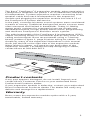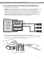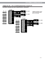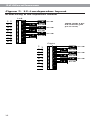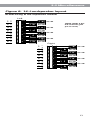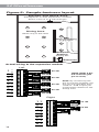
1
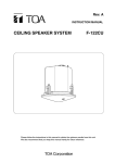
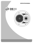
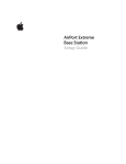
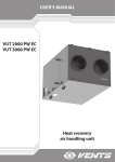
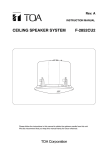
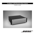
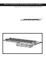
Bose® FreeSpace® 6 Business Music System
Expansion Module Installer’s Guide
Safety
Warning
To reduce the risk of fire or electric shock, do not expose
the expansion module or FreeSpace® 6 business music
system to rain or moisture.
CAUTION
RISK OF ELECTRICAL SHOCK
DO NOT OPEN
CAUTION: TO REDUCE THE RISK OF ELECTRIC SHOCK,
DO NOT REMOVE COVER (OR BACK).
NO USER-SERVICEABLE PARTS INSIDE.
REFER SERVICING TO QUALIFIED PERSONNEL.
These CAUTION marks are located on your FreeSpace
business music system:
The lightning flash with arrowhead symbol, within an
equilateral triangle, is intended to alert the user to the
presence of uninsulated dangerous voltage within the
system enclosure that may be of sufficient magnitude
to constitute a risk of electric shock.
The exclamation point within an equilateral triangle, as
marked on the system, is intended to alert the user to
the presence of important operating and maintenance
instructions in this installer’s guide.
Installation should be by a qualified installer.
Table of Contents
Product contents, Warranty ................................................. 3
1.1 Applications ................................................................... 4
1.2 Loudspeaker placement ................................................ 4
1.3 Polarity ........................................................................... 4
2.1 Expansion module installation ....................................... 5
3.1 Asymmetrical loads ........................................................ 7
3.2 Wiring considerations .................................................... 7
3.3 Wire in a plenum space .................................................. 7
Figure 1: Checkerboard pattern .......................................... 8
Figure 2: 3–Loudspeaker layout .......................................... 9
Figure 3: 5–Loudspeaker layout .......................................... 9
Figure 4: 6–Loudspeaker layout ........................................ 10
Figure 5: 7–Loudspeaker layout ........................................ 10
Figure 6: 8–Loudspeaker layout ........................................ 11
Figure 7: 12–Loudspeaker layout ...................................... 12
Figure 8: 16–Loudspeaker layout ...................................... 13
Figure 9: Sample business layout ..................................... 14
2
Introduction
The Bose® FreeSpace® 6 expansion module, when used with a
FreeSpace 6 amplifier can power 1 to 12 additional FreeSpace
6 loudspeakers. System expansion requires connecting loudspeaker cable from each loudspeaker to the expansion
module and plugging the expansion module into block 13 of
the FreeSpace 6 system electronics.
In the past, commercial stereo sound systems were considered
a waste of money. Traditional background music sources were
often monaural and limited in bandwidth. Today, hi-fidelity
stereo music systems for commercial use are simple and
affordable because of high quality stereo music programming
and the Bose FreeSpace 6 business music system.
®
The wide beamwidth of the FreeSpace 6 loudspeakers (150º)
makes achieving stereo in commercial spaces easy even in low
ceiling environments. Bose recommends using a “checkerboard” pattern (Figure 1, page 8) when wiring for stereo. For
simplicity, many of the expansion illustrations in this manual
show just the left or the right side of the expansion module.
When wiring in stereo, you need to use both sides of the
expansion module. For additional help designing in stereo,
contact Bose at 508-994-2673.
Product contents
If any part appears damaged, do not install. Repack and
contact Bose Customer Service or your authorized Bose
Professional Products dealer.
If your expansion module is defective, contact your authorized
Bose Professional Products dealer. The dealer will verify any
defects and arrange for a replacement.
Warranty
Bose covers the expansion module option with a 5-year,
transferable, limited warranty.
3
1.0 Setting Up
1.1 Applications
To assist in planning the installation, Figures 2 through 9
(pages 9–14) illustrate typical configurations with recommended wiring guidelines.
Note: The normalized SPL estimate given for each configuration is based on the FreeSpace® 6 loudspeaker sensitivity
measured at 1W @ 1 m. Actual SPL measurements may vary
depending upon ceiling height, loudspeaker spacing, and
cable losses (see Section 3.2, Wiring considerations).
Note: There may be instances when an installation requires an
odd number of loudspeakers, that is, 3, 5, or 7 per channel.
This expansion module makes these possible.
The 5– and the 7–loudspeaker configurations will yield output
variances between the loudspeakers connected to the odd
loudspeaker channel. The recommended wiring configurations
are shown in the following figures.
1.2 Loudspeaker placement
Consult the Bose® FreeSpace 6 Business Music Systems
Installer’s Guide for complete loudspeaker placement guidelines.
1.3 Polarity
For correct phasing between loudspeakers, connect them with
consistent polarity. While incorrect phasing does no physical
harm, it diminishes the bass response.
• Connect the (–) at the expansion module loudspeaker outputs
to the (–) at the loudspeaker terminals.
• Connect the (+) at the expansion module loudspeaker outputs
to the (+) at the loudspeaker terminals.
4
2.0 Installation
2.1 Expansion module installation
1. Route each loudspeaker’s cable from the loudspeaker to
the expansion module.
Note: It is not necessary to connect any one loudspeaker to
another. All loudspeaker networking is accomplished
within the expansion module. The following illustration
shows how the expansion module works. Although you wire
each loudspeaker to the expansion module individually, the
expansion module interprets your wiring to produce the
effect of loudspeaker A being wired to loudspeaker B and
loudspeaker B being wired to loudspeaker C.
Schematic
FS6
Amp
Out
Expansion
Module
LEFT
RIGHT
+
–
+
–
a
+
–
b
+
–
c
(One channel)
2. Strip the loudspeaker wire to 1/4 inch (6 mm).
Stranded wire is recommended. Do not solder (tin) the wires.
3. Secure each cable to the expansion module block using a
1/8 inch (3 mm) flat blade screwdriver.
5
2.0 Installation
4. Turn off the FreeSpace® 6 system electronics and plug
the expansion module, with attached loudspeaker wires,
into block 13 of the system electronics.
Secure the expansion module to the system electronics
using the two screws provided. Do not over tighten
them.
®
B
A
5. Place the cover on the FreeSpace 6 system electronics.
Phono cable
inputs
Low level
inputs/outputs
Loudspeaker
connections
®
B
A
6. Turn on the FreeSpace 6 system electronics.
The loudspeakers are now ready for use.
6
3.0 Miscellaneous
3.1 Asymmetrical loads
Some applications may require the FreeSpace® 6 amplifier to
drive varying numbers of loudspeakers from each channel.
Often this is a dual–zone application in which one zone requires
few loudspeakers and another zone requires many loudspeakers to achieve ample coverage.
Note: When using the expansion module in a dual-zone application, there may be a difference in maximum output between
the two channels. The greater the number of loudspeakers connected to a single channel, the less power each loudspeaker
receives.
An example of this type of application is the dual–zone restaurant installation shown in Figure 9 (page 14). Both zones require
music; only the lounge requires paging.
The dining area is a larger room than the lounge and requires 8
loudspeakers. A low SPL is required to drive the loudspeakers
comfortably over the ambient noise floor (in this case, a maximum of 2 Watts per loudspeaker).
Although the lounge is smaller in total volume, its ambient
noise floor is higher. In order for customers to hear paging
announcements, each loudspeaker requires more than 2 Watts.
Four loudspeakers provide adequate coverage in the lounge.
For technical assistance, call the Bose® Application and Design
Support hotline at 1-800-992-2673 or contact your authorized
Bose Professional Products dealer.
3.2 Wiring considerations
Use stranded, heavy gauge wire for loudspeaker connections.
As a rule, the greater the distance between the amplifier and
the loudspeakers, the larger the wire diameter needs to be for
minimal power loss. For best performance from the FreeSpace
6 system, use the following table as a guide:
Wire Diameter SPL Loss per Loudspeaker Cable Length
(AWG/mm2)
25 ft/8 m 50 ft/15 m 100 ft/30 m 200 ft/60 m
18/0.75
Negligible
SPL loss
16/1.5
OK
14/2.5
OK
12/4.0
OK
Not
Not
recommended recommended
Negligible
SPL loss
Not
recommended
Not
recommended
Not
recommended
OK
Negligible
SPL loss
Not
recommended
OK
OK
Negligible
SPL loss
3.3 Wire in a plenum space
Both UL and CSA permit the use of Class 2 wire (CL2, CL2P,
or CL2R) for loudspeaker wire. If the wire passes through a
plenum, only CL2P is acceptable. In risers such as vertical airhandling ducts or any through passage from floor-to-floor,
CL2R is classified for this use.
See Table 725-53 of the National Electric Code (NEC) for a list
of acceptable wire substitutes.
7
3.0 Miscellaneous
Figure 1: Checkerboard pattern
Left
8
Right
L
R
R
L
L
R
R
L
3.0 Miscellaneous
Figure 2: 3–Loudspeaker layout
Actual wiring to the expansion module
1–
+
2–
+
3
4
5
6
7
8
–
+
–
+
–
+
–
+
–
+
–
+
–
+
–
+
b
a
89 dB
89 dB
–
+
c
89 dB
a
83 dB
Figure 3: 5–Loudspeaker layout
Actual wiring to the expansion module
1–
+
2–
+
3–
+
–
+
–
+
b
4–
+
5–
+
6–
+
83 dB
–
+
–
+
d
c
83 dB
86 dB
–
+ e 86 dB
7–
+
8–
+
9
3.0 Miscellaneous
Figure 4: 6–Loudspeaker layout
Actual wiring to the expansion module
Left
1–
+
–
+
a
89 dB
2–
+
–
+
b
4–
+
89 dB
–
+ c 89 dB
–
+
d
89 dB
3–
+
5–
+
6–
+
7–
+
–
+
–
+
f
e
89 dB
89 dB
8–
+
Figure 5: 7–Loudspeaker layout
Actual wiring to the expansion module
1–
+
2–
+
3
4
5
6
7
8
10
–
+
–
+
–
+
–
+
–
+
–
+
–
+
–
+
b
a
82 dB
82 dB
–
+
c
82 dB
–
+
d
85 dB
–
+ e 85 dB
–
+
f
85 dB
–
+ g 85 dB
3.0 Miscellaneous
Figure 6: 8–Loudspeaker layout
Actual wiring to the expansion module
Left
1–
+
2
3
4
5
6
7
8
–
+
–
+
–
+
–
+
–
+
–
+
–
+
–
+
a
90 dB
–
+
b
90 dB
–
+ c 90 dB
–
+
d
90 dB
(84dB–90dB if the
left channel gain
pot is used)
Right
1–
+
2–
+
3
4
5
6
7
8
–
+
–
+
–
+
–
+
–
+
–
+
–
+
a
90 dB
–
+
b
90 dB
–
+ c 90 dB
–
+
d
90 dB
11
3.0 Miscellaneous
Figure 7: 12–Loudspeaker layout
Actual wiring to the expansion module
Left
1
2
3
4
5
6
7
8
–
+
–
+
–
+
–
+
–
+
–
+
–
+
–
+
–
+
a
89 dB
–
+
b
89 dB
–
+ c 89 dB
–
+
d
89 dB
–
+ e 89 dB
–
+
f
89 dB
(83dB–89dB if the
left channel gain
pot is used)
Right
1–
+
2
3
4
5
6
7
8
12
–
+
–
+
–
+
–
+
–
+
–
+
–
+
–
+
a
89 dB
–
+
b
89 dB
–
+ c 89 dB
–
+
d
89 dB
–
+ e 89 dB
–
+
f
89 dB
3.0 Miscellaneous
Figure 8: 16–Loudspeaker layout
Actual wiring to the expansion module
Left
1–
+
2
3
4
5
6
7
8
–
+
–
+
–
+
–
+
–
+
–
+
–
+
–
+
a
88 dB
–
+
b
88 dB
–
+ c 88 dB
–
+
d
88 dB
–
+ e 88 dB
–
+
f
88 dB
–
+ g 88 dB
–
+
h
88 dB
(82dB–88dB if the
left channel gain
pot is used)
Right
1–
+
2–
+
3
4
5
6
7
8
–
+
–
+
–
+
–
+
–
+
–
+
–
+
a
88 dB
–
+
b
88 dB
–
+ c 88 dB
–
+
d
88 dB
–
+ e 88 dB
–
+
f
88 dB
–
+ g 88 dB
–
+
h
88 dB
13
3.0 Miscellaneous
Figure 9: Sample business layout
Kitchen and Stock Area
FreeSpace ® 6 with expansion module.
Music source is a CD changer.
e
f
a
Dining Area
Music only in this area
g
b
h
Bar
Music and Paging
in this area
c
j
i
d
Hostess
Station
k
Paging Mic
l
Entrance
Actual wiring to the expansion module
Left
1
2
3
4
5
6
7
8
–
+
–
+
–
+
–
+
–
+
–
+
–
+
–
+
–
+
e
88 dB
–
+
f
88 dB
–
+ g 88 dB
–
+
h
88 dB
–
88 dB
+ i
–
+
j
88 dB
–
+ k 88 dB
–
+
l
88 dB
(82dB–88dB if the
left channel gain
pot is used)
Note: By connecting the
bar to the left amplifier, the
bar can be operated from
+2dB to –4dB output per
loudspeaker relative to the
dining area.
Right
1–
+
2–
+
3
4
5
6
7
8
14
–
+
–
+
–
+
–
+
–
+
–
+
–
+
a
90 dB
–
+
b
90 dB
–
+ c 90 dB
–
+
d
90 dB
15
© 1995 Bose Corporation, The Mountain, Framingham, MA 01710-9168 USA
JN95766 PN178160 8/95