1
FANUC SERIES 21i/18i/16i – TA
Concise guide
Edition 03.01
_____________________________________________________________________
0.1 GENERAL INDEX- CONCISE GUIDE FOR PROGRAMMER
PAGE
PAR.
CONTENTS
7
1.0
FOREWORD
8
2.0
NC MAIN FUNCTIONS AND ADDRESSES
8
2.1
O
Program and sub-program number
8
2.2
N
Block number
9
2.3
G
Preparatory operations
9
2.4
X/Z/B/Y
Movement absolute co-ordinates
10
2.5
U/W
Movement incremental co-ordinates
12
2.6
F
Work feed
12
2.7
S
Spindle rotation speed
13
2.8
T
Tool selection
15
2.9
M
Auxiliary functions
18
2.10 M
Other auxiliary functions
19
2.11 /
Skipping a block
19
2.12 ( )
Notes and comments
20
3.0
ISO PROGRAMMING
20
3.1
G0
Linear axes rapid traverses
21
3.2
G1
Work linear interpolation
24
3.3
G1 A..
Programming with angles
28
3.4
G2/G3
Circular interpolations
30
3.5
G4
Axis pause time
31
3.6
G95
Feed in mm/rev
31
3.7
G94
Feed in mm/min
32
3.8
G97
Fixed revolutions spindle rotation
33
3.9
G96
Constant cutting speed
34
3.10 G92
Spindle revolution limitations
35
3.11 G33
Thread cutting movements
37
3.12 G41/G42/G40
Tool radius compensation
41
3.13 G54/G59
Workpiece origins
43
3.14 G52
Origin transfer by program
_____________________________________________________________________
CONCISE GUIDE FANUC
2
_____________________________________________________________________
PAGE
PAR.
CONTENTS
44
3.15 M134/M135
Precise stop
45
3.16 G
List of main “G” preparatory functions
47
4.0
FIXED FANUC CYCLES
47
4.1
G71
Material removal by turning
53
4.2
G72
Material removal by facing
57
4.3
G73
Profile repetition
60
4.4
G70
Finishing cycle
63
4.5
G174
Radial grooves rough machining/pre-finishing cycle
67
4.6
G176
Axial grooves rough machining/pre-finishing cycle
72
4.7
G175/G177
Finishing cycle for radial/axial grooves
76
4.8
G76
Thread cutting cycle in several cuts
81
4.9
G83
Front drilling cycle
83
4.10 G84
Front tapping cycle
85
5.0
SUB-PROGRAMS / PARAMETRIC PROGRAMMING
85
5.1
M98 M99
Use of sub-programs
89
5.2
#
Parametric programming
93
6.0
BACK SPINDLE MACHINING
93
6.1
Most important addresses used
94
6.2
95
6.3
98
6.4
101
M
Auxiliary functions
Example of machining with back spindle
O9100
6.5
O9101
O9102
Workpiece change-over with parting off
Workpiece change-over with parting off without extraction
104
6.6
Workpiece change-over without parting off
106
7.0
106
7.1
Motor driven tools
108
7.2
Motor driven tools reset
109
7.3
110
7.4
111
7.5
M20/M21
Use of spindle brake
112
7.6
G83
Front drilling cycle
115
7.7
G87
Radial drilling cycle
AXIS C MACHINING AND MOTOR DRIVEN TOOLS
M37
Axis “C”
Programming in real co-ordinates
_____________________________________________________________________
CONCISE GUIDE FANUC
3
_____________________________________________________________________
PAGE
PAR.
CONTENTS
118
7.8
O9103
Front tapping sub-program
121
7.9
O9104
Radial tapping sub-program
124
7.10 G112
Programming in imaginary co-ordinates
127
7.11 G2/G3
Circular interpolation in G112
129
7.12 G41 G42 G40
Milling radius offset in G112
131
7.13 G107
Cylindrical interpolation
135
7.14
Programming with real Y axis
138
8.0
BAR MACHINING
138
8.1
Example of machine tool loader use with back spindle
140
8.2
Example of machine tool loader use without back spindle
142
8.3
Ex. of machine tool push-bar conveyor use with back spindle
143
8.4
Ex. of machine tool push-bar conveyor use without back spindle
144
8.5
Example of pull-bar conveyor use
OPERATOR READY REFERENCE GENERAL INDEX
146
12.0
MACHINE START UP
146
12.1
Power-on
146
12.2
Execution of axes reference
146
12.3
Write protection key
147
13.0
PROGRAMME MANAGEMENT
147
13.1
How to create a new programme
147
13.2
How to modify an existing programme
147
13.3
How to insert a code (or a block) in a programme
147
13.4
How to modify or replace a code
148
13.5
How to delete a code
148
13.6
How to delete a block
148
13.7
How to copy /paste part of a programme
148
13.8
How to copy a programme
149
13.9
How to delete a programme
149
13.10
How to rename a programme
149
13.11
Selection of a programme for machining
_____________________________________________________________________
CONCISE GUIDE FANUC
4
_____________________________________________________________________
PAGE
PAR.
CONTENTS
150
13.12
Creation of a new subprogram
150
13.13
Graphic simulation of a programme
151
13.14
Running of the programme in automatic cycle
151
13.15
Interruption of programme execution
151
13.16
How to start the programme from an intermediate stage
151
13.17
Background editing
152
14.0
TOOL RESET
152
14.1
Manual tool reset
153
14.2
Centre reset
153
14.3
Internal machining tools reset
153
14.4
Tool reset on subspindle
153
14.5
Tool reset with probe (optional)
154
14.6
Tool reset for TWIN machines
155
14.7
Tool table management
155
14.8
Tool fine correction
155
14.9
Entry of insert radius
156
14.10
Entry of tool orientation
156
14.11
Entry of cutter radius
157
15.0
ORIGIN MANAGEMENT
157
15.1
Origin measurement
157
15.2
Origin modification
158
16.0
MACHINE PARAMETERS
158
16.1
How to modify a machine parameter
159
17.0
SETTING OF CTX300 TAILSTOCK
159
17.1
Instructions to be inserted in the program
159
17.2
Tailstock double speed option
160
17.3
Tailstock repositioning
161
18.0
CTX SERIES TAILSTOCK AND REST
161
18.1
Manual movement of tailstock and rest
161
18.2
Instructions to insert in program
_____________________________________________________________________
CONCISE GUIDE FANUC
5
_____________________________________________________________________
PAGE PAR.
CONTENTS
163
19.0
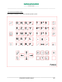
KEYBOARD AND OPERATOR’S PANEL
163
19.1
Description of keys on the operator’s panel
167
19.2
Description of keys on the MDI panel
170
19.3
Selector switch and keys below the operator’s panel
172
20.0
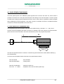
SERIAL PORT COMMUNICATION
172
20.1
Setting of data transfer parameters
172
20.2
Cable scheme
174
20.3
Transmission programs
176
20.4
How to copy a programme to the serial port
176
20.5
How to copy a programme from the serial port
176
20.6
How to copy a programme to memory card
177
20.7
How to copy a programme from memory card
_____________________________________________________________________
CONCISE GUIDE FANUC
6
_____________________________________________________________________
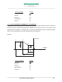
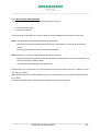
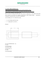
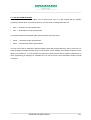
1.0 FOREWORD
On an NC machine tool the sequence of the instructions programmed to process a workpiece consists of
codes which are made up of functions or addresses with a relevant numeric value.
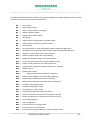
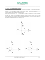
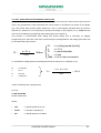
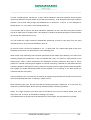
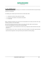
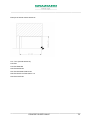
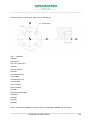
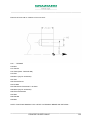
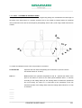
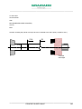
When preparing a part program the tool path is imagined referring to a system of co-ordinates, the origin
of which (
=> zero point to which all the dimensions refer) can be chosen. In the specific case of
an NC lathe this co-ordinates system is composed of two or more axes:
• axis X (for diameters).
• axis Z (for lengths).
• axis C (for angle divisions on lathes
with controlled spindle).
• axis B (for the longitudinal position of the back spindle
on machines fitted with this option).
• axis A (for angle division on lathes with controlled
back spindle).
X+
X+
C+
Z+
A+
B-
The tool path is programmed with co-ordinated points written in the correct sequence and established
according to the workpiece profile. Each movement of the tool along this path is written as a separate
instruction (block) together with any technological data required. The group of blocks forms the “PART
PROGRAM”.
_____________________________________________________________________
CONCISE GUIDE FANUC
7
_____________________________________________________________________
2.0 NC MAIN FUNCTIONS AND ADDRESSES
The sequence of instructions that make up the program consists of letters and numbers, each of which
has a specific significance.
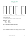
2.1 “O” PROGRAM AND SUB-PROGRAM NUMBER
The letter O followed by a number indicate the programs and the sub-programs. The number paired with
the letter O can range from 1 to 9999. To have better program management Graziano suggests that the
following values are paired :
From O1 to O8000 Main Programs available for the customer
From O8001 to O8999 Sub-programs available for the customer
From O9000 to O9999 Sub-programs available for GRAZIANO to create special macros that cannot be
modified by the customer since they are protected by a parameter.
The NC memory can contain a maximum of 63, between Programs and Sub-programs, or a maximum of
32000 characters.
2.2 “N” BLOCK NUMBER
A block is a group of words that identify the operation to be carried out.
Example:
N10 G0 X200 Z5 M8
Each block is identified by a sequential number N, from 0 to 9999 and must end with the end of block EOB
character ( ; )
The block number is entered automatically by the NC when an end of block EOB code is inserted ( ; ).
Through a machine datum (N. 3216) the increment value can be selected in the block numbering: unitary (
N1 N2 N3 etc.) or decimal (N10 N20 N30 etc.)
It is up to the programmer whether to use the block number or not.
To use the block number a value 1 has to be assigned to the setting datum SEQUENCE NO. in the
Prepare/Manual menu which can be entered by pressing the SETTING key on the MDI keyboard
Usually the block numbering is not enabled.
_____________________________________________________________________
CONCISE GUIDE FANUC
8
_____________________________________________________________________
2.3 “G” PREPARATORY OPERATIONS
The G code prepares the control to carry out certain operations that differ according to the number that
follows this code (e.g.: G0, G1, G3, etc.).
There are two types of preparatory functions: modal functions and self-deletion functions. The former
remain active until they are cancelled by other modal functions, the latter are only active in the block
where they are entered.
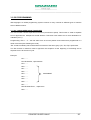
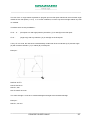
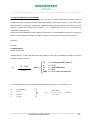
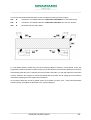
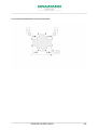
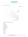
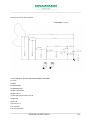
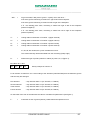
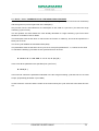
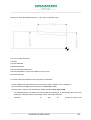
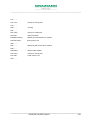
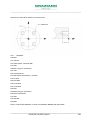
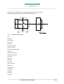
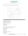
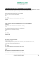
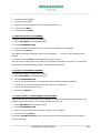
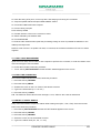
2.4 “X Z B Y” MOVEMENT ABSOLUTE CO-ORDINATES
Codes X and Z define the absolute co-ordinates referring to the workpiece zero. X determines diameters
(diametrical programming); Z determines the lengths; B determines the back spindle axis movements
(only on machines where this option is installed); Y determines the motor driven turret Y axis movements
(only on machines where this option is installed) .
These codes can be programmed with a positive or a negative sign. If no sign is programmed the value is
considered positive. Values can be programmed with up to three digits after the decimal point.
Example:
X+
4
3
1
∅ 40
∅ 80
2
Z+
20
50
70
_____________________________________________________________________
CONCISE GUIDE FANUC
9
_____________________________________________________________________
X / Z Co-ordinates
Position
N5 X0 Z0
N6 X40
(1)
N7 Z-20
(2)
N8 X80 Z-50
(3)
N9 Z-70
(4)
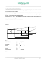
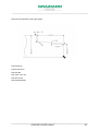
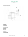
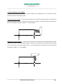
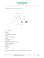
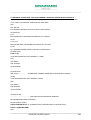
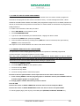
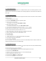
2.5 “U and W” MOVEMENT INCREMENTAL CO-ORDINATES
Codes U and W define the incremental co-ordinates referring to the last programmed point. U defines a
movement on axis X (diametrical programming); W defines a movement on axis Z. These codes can be
programmed with a positive or a negative sign. If no sign is programmed the value is considered positive.
Values can be programmed with up to three digits after the decimal point.
Example:
X(U)+
4
3
1
∅ 40
∅ 80
2
Z(W)+
20
50
70
U / W Co-ordinates
Position
N5 X0 Z0
N6 U40
(1)
N7 W-20
(2)
N8 U40 W-30
(3)
N9 W-20
(4)
_____________________________________________________________________
CONCISE GUIDE FANUC
10
_____________________________________________________________________
The first program start value and the first position of each tool must always be programmed in absolute
co-ordinates. It is possible to program an absolute co-ordinate and an incremental co-ordinate in the same
block, providing they do not refer to the same axis.
Example:
N10 G0 X100 W-5
; correct
N10 G0 U10 Z100
; correct
N30 G0 X100 U20
; not correct
_____________________________________________________________________
CONCISE GUIDE FANUC
11
_____________________________________________________________________
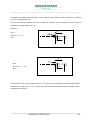
2.6 “F” WORK FEED
Function F (Feed) defines the work feed and can have two different significances, according to which
preparatory G function is active (G95 or G94 see par. 3.6 and par. 3.7):
• mm/rev
(usually used for turning operations).
• mm/min
(usually used for milling operations or for work movements with spindle stationary).
The programmed feed F can be modified through the axis trimmer with a variable value from 0% to 120%.
The programmed feed F remains active until another is selected.
2.7 “S” SPINDLE ROTATION SPEED
Function S (Speed) defines the rotation speed of the spindle. It can have two different significances,
according to which preparatory G function is active (G97 or G96 see par. 3.8 and par. 3.9):
• rpm
(usually used for machining without wide diameter variations e.g.: drilling, tapping and
thread cutting).
• m/min
(usually used for all turning operations).
The programmed speed can be changed through the spindle trimmer with a variable value from 50% to
120%.
_____________________________________________________________________
CONCISE GUIDE FANUC
12
_____________________________________________________________________
2.8 “T” TOOL SELECTION
Code T (Tool) defines the tool corrector and the position of the turret to be activated for machining. The
tool corrector contains information that identifies the characteristics (length, direction, radius etc.) of the
tool. When programming, the tool setting is always composed of 3 or 4 digits. The first number, or first
pair of numbers, defines the position of the tool in the turret; this number is therefore usually between 1
and 12.
The second pair of numbers, always composed of two digits, identifies the corrector matched to the tool.
The control memory usually has available 32 tool correctors; therefore the programmer has to select the
corrector to match to each individual tool.
For simpler operation it is suggested to match a tool number to the same corrector number.
Example:
N1 T101
N2 ……….
N3 ……….
Machining with tool T1 corrector 01
N4 ……….
1
N5 ……….
N6 ……….
N7 T404
N8 ……….
N9 ……….
Machining with tool T4 corrector 04
N10 ……….
N11 ……….
Under certain circumstances it is possible to match a tool with a different corrector, for example to move
the position of a tool in the turret without having to reset it again.
Example:
N4 T121
; Tool selection T1 with corrector 21
N5 ……….
N6 ……….
Machining
N7 ……….
N8 ……….
_____________________________________________________________________
CONCISE GUIDE FANUC
13
_____________________________________________________________________
When a tool is called up, the turret rotates so as to follow the shortest path, whether clockwise or anticlockwise.
In the machines provided with hydraulic turrets, there are two functions to select the desired turret rotation
direction. These functions are M16 and M46.
M16 forces the clockwise rotation of the turret disk.
M46 forces the anti-clockwise rotation of the turret disk.
Example:
N3 ……….
N4 T101
; Tool selection T1 shortest path
N5 ……….
N6 T303 M16
; Tool selection T3 in clockwise rotation
N7 ……….
N8 T606 M46
; Tool selection T6 in anti-clockwise rotation
N9 ……….
In some cases it may be useful to make movements without any corrector active or rather, without taking
into account the tool length, for example to bring the turret in the smallest overall dimension zone when
using automatic loaders or such like. The function that disables the tool correctors is T0. To reactivate the
correctors it is sufficient to call up a tool.
T0 does not rotate the turret disk.
_____________________________________________________________________
CONCISE GUIDE FANUC
14
_____________________________________________________________________
2.9 “M” AUXILIARY FUNCTIONS
Auxiliary functions are used to send commands to the control and to the machine tool and they are divided
between functions that become operational as soon as they are read, and functions that become operative
at the end of block (M0, M1, M3, M4)..
The list below indicates the most commonly used M auxiliary functions :
M0 => Stop program . Interrupts the program running and stands by until it receives consent to continue
from the operator (start cycle).
M1 => Stop program-optional. When active it interrupts the program running and stands by until it receives
consent to continue from the operator (start cycle).
To activate this command see paragraph 19.1
M3 => Clockwise spindle rotation. The spindle rotates clockwise at the previously set speed S.
M4 => Spindle anti-clockwise rotation. The spindle rotates anti-clockwise at the previously set speed S
M5 => Spindle rotation stop. This function stops the spindle rotation
M8 => Open coolant. This function activates the delivery of the coolant. The spindle rotation influences the
function activation: if the spindle is not rotating the coolant delivery is deactivated.
M9 => Stop coolant. This function stops the delivery of the coolant.
M13 => Spindle clockwise rotation at previously set speed S and coolant delivery activated.
M14 => Spindle anti-clockwise rotation at previously set speed S and coolant delivery activated.
M19 => Spindle orientation. This function stops the spindle in a defined angle position. M19 can be
programmed also with the spindle rotating. The stopping angle is programmed through the optional
address S. The M5 function must always be programmed after this function .
Example:
N22 ……
N23 M19 S45
N24 M5
N25 ……
M30 => End of program. This function terminates the running of the program and sets the NC to start from
the first block.
_____________________________________________________________________
CONCISE GUIDE FANUC
15
_____________________________________________________________________
The M functions listed below are used for many specific applications. Details regarding the use of these
functions can be found in the machine documentation.
M0
➪ stop program
M1
➪ optional stop program
M2
➪ end of program (without re-winding)
M3
➪ spindle clockwise rotation
M4
➪ spindle anti-clockwise rotation
M5
➪ stop spindle
M7
➪ coolant delivery not depending on spindle rotation
M8
➪ coolant delivery depending on spindle rotation
M9
➪ cut off coolant
M10 ➪ air blast activation to clean jaws (spindle rotation enabled with jaws open)
M11 ➪ deactivation of jaw cleaning air blast (spindle rotation disabled with jaws open)
M12 ➪ reduction of self-centring chuck locking pressure
M13 ➪ spindle clockwise rotation and coolant delivery
M14 ➪ spindle anti-clockwise rotation and coolant delivery
M16 ➪ force turret clockwise direction (only for hydraulic turrets)
M18 ➪ restore normal pressure to self-centring chuck lock
M19 ➪ spindle direction (M19 Sxx directs the spindle to xx degrees)
M20 ➪ spindle brake on
M21 ➪ spindle brake release
M22 ➪
tailstock sleeve forward feed with conditioning
M23 ➪ tailstock sleeve backward movement with conditioning
M24 ➪ tailstock sleeve forward feed without conditioning
M25 ➪ tailstock sleeve backward movement without conditioning
M26 ➪ automatic sliding guard opening
M27 ➪ automatic sliding guard closing
M30 ➪ end of program ( with winding)
M31 ➪ conditionings suspended on next tool change
M32 ➪ steady rest release from bench and hooking onto carriage
M33 ➪ steady rest release from carriage and hooking onto bench
M36 ➪ axis C disengagement
M37 ➪ axis C engagement
M38 ➪ tool reset sensor in working position
M39 ➪ tool reset sensor in home position
M46 ➪ force turret anti-clockwise direction (only for hydraulic turrets)
_____________________________________________________________________
CONCISE GUIDE FANUC
16
_____________________________________________________________________
M52 ➪ tailstock release from bench and hooking onto carriage
M53 ➪
tailstock release from carriage and hooking onto bench
M58 ➪ spindle and reset sensor orientation in work position
M62 ➪
workpiece counter increment on display (only active in automatic mode)
M63 ➪ external robot call to change workpiece (optional)
M64 ➪ workpiece released indication to external robot (optional)
M65 ➪
workpiece locked indication to external robot (optional)
M67 ➪
command / wait for bar change to loader (optional)
M68 ➪
self-centring chuck /collet chuck closure
M69 ➪ self-centring chuck /collet chuck opening
M74 ➪
second steady rest arms opening (optional)
M75 ➪ second steady rest arms closing (optional)
M78 ➪ bar measurement check (option) for Irco loader
M79 ➪
bar at end of stroke check (option) for Irco loader
M84 ➪
steady rest arms opening
M85 ➪
steady rest arms closing
M86 ➪
retractable steady rest in working position (up)
M87 ➪ retractable steady rest in home position (down)
M88 ➪
workpiece unloading arm in home position (down)
M89 ➪ workpiece unloading arm in working position (up)
M90 ➪
probe parameters memorisation at PMC ( from #812 to #822)
M100 ➪
temporary suspension of active S
_____________________________________________________________________
CONCISE GUIDE FANUC
17
_____________________________________________________________________
2.10 “M” OTHER AUXILIARY FUNCTIONS
The list below indicates other M functions used for many specific applications. Details regarding the use of
these functions can be found in the machine documentation.
M29
➪ rigid tapping on spindles (cannot be used with motor driven tools)
M98
➪ sub-program call up (M98 P…)
M99
➪ return from sub-program
M127 ➪ deactivates M128/M129/M130 and immediately stops the conveyor
M128 ➪ conveyor pulsed movement in cycle (counter C11 in minutes)
M129 ➪ conveyor intermittent movement in cycle (counter C10/C11 in minutes)
M130 ➪ conveyor continuous movement in cycle
M131 ➪ turret pre-release
M922 ➪ sleeve thrust enabled
M923 ➪ sleeve thrust suspended (if thrust switch is set to 1)
M950 ➪ self-centring chuck pedal disabled
M951 ➪ self-centring chuck pedal re-enabled
M966 ➪ spintor feed suspend (for barfeeder IEMCA)
M967 ➪ spintor feed restart (for barfeeder IEMCA)
M968
barfeeder thrust suspend
M969 ➪ push-bar conveyor thrust restored
M970 ➪ push-bar conveyor use disabled
M971 ➪ push-bar conveyor use restored
M984 ➪ external workpiece pick-up (shafts)
M985 ➪ internal workpiece pick-up (flanges)
M995 ➪ emergency light on
M999 ➪ machine tool cut off by program (NC remains on)
_____________________________________________________________________
CONCISE GUIDE FANUC
18
_____________________________________________________________________
2.11 “ / “ SKIPPING A BLOCK
This function is used to run or exclude the marked block.
To activate or exclude this function use the relevant key on the operator panel (“see paragraph 19.1)
- With the key warning light off the barred blocks are run.
- With the key warning light on the barred blocks are skipped.
Example:
N10 /T101
N20 /G54
N30 /G92 S2000
N40 /G96 S180 M4
N50 /G0 X100 Z2 M8
N60 /G1 Z-40 F0.25
2.12 NOTES AND COMMENTS
For programming requirements comments and notes can be entered into the program, for example an
indication of the type of tool next to the block where that tool is selected.
These notes can be entered in round brackets (...)
•
(…) a note written in round brackets can contain up to 30 characters, and is visible both during
programming and when the program is run
Example:
N10 T101 (EXTERNAL ROUGH MACHINING TOOL)
or
N18 M0 (TURN THE WORKPIECE)
_____________________________________________________________________
CONCISE GUIDE FANUC
19
_____________________________________________________________________
3.0 ISO PROGRAMMING
ISO language is a unified programming system common to many controls on different types of machine
tools of different nature.
3.1 “G0” LINEAR AXES RAPID TRAVERSES
The “G0” function controls rapid axis movement (at maximum speed). This function is used to separate
from or approach the workpiece at a safe distance. This block must contain one or more destination coordinates (X e Z ).
Programming “G0 X… Z...” the tool starts from its current position and reaches that programmed in a
linear movement (thus following the route).
“G0” remains modularly active until another movement of the same group (G1, G2, G3) is performed.
The G0 function is therefore used to approach the workpiece at the beginning of machining and to
separate from it at the end of cycle.
Example:
N17 …….
N18 G0 X50 Z2 ; rapid traverse
N19 …….
N20 …….
N21 …….
N22 …….
N23 …….
MACHINING
N24 …….
N25 …….
N26 …….
N27 …….
N28 G0 X200 Z100 ; rapid return
N29 …….
_____________________________________________________________________
CONCISE GUIDE FANUC
20
_____________________________________________________________________
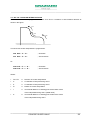
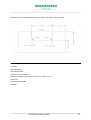
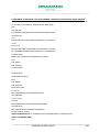
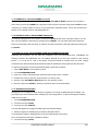
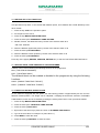
3.2 “G1” WORK LINEAR INTERPOLATION
The “G1” function controls a linear work movement (at a programmed speed). This function is used to
carry out machining on the workpiece.
With this function it is the programmer who decides the speed (feed “F”) at which the tool is to reach the
programmed point. The same block must also contain one or two destination co-ordinates (X and Z) and
the feed (F) if this has not been inserted beforehand.
Programming “G1 X… Z... F…” the tool starts from its current position and reaches that programmed in a
linear movement at the work speed.
Function “G1” and work feed “F” are modal functions.
Example:
6
X
5
4
3
1
0
∅ 30
∅ 50
2
Z
2x45°°
30
65
95
N1 ……
N2 G0 X26 Z3
(0)
N3 G1 Z0 F0.2
(1)
N4 X30 Z-2
(2)
N5 Z-30
(3)
N6 X50 Z-65 F0.1
(4)
N7 Z-95
(5)
N8 G0 X100 Z30
(6)
Approach
Turning
Separation
N9 ……
_____________________________________________________________________
CONCISE GUIDE FANUC
21
_____________________________________________________________________
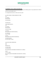
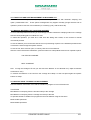
The linear movement programmed with G1 can be linked to the movement of the next block by a chamfer
(,C) or a connecting radius (R).
For two-axis machines (without the axis C option) the chamfer can be identified by just the letter C
followed by the value (and not by ,C)
Example:
N12 …..
N13 G1 X… Z… ,C…
Z
,C
N14 …..
,C
X
Z
R
N12 …..
N13 G1 X… Z… R…
R
X
N14 …..
These functions can only be programmed in a “G1” block. It is also important to underline that the block
following one containing “R” or “,C” must be a G1 work movement so that the chamfer or radius can be
calculated by the control.
_____________________________________________________________________
CONCISE GUIDE FANUC
22
_____________________________________________________________________
Example of how to use the R and ,C functions:
24
12
40
Chamfers 2x45º
Ø35
Ø55
Ø75
R4
N5 ……
N6 G0 X0 Z3
Approach
N7 G1 Z0 F0.2
N8 X35 ,C2
N9 Z-40 R4
Profile description
N10 X55 Z-52 F0.1
N11 X75 ,C2
N12 Z-76
N13 G0 X100 Z50
Separation
N14 ……
_____________________________________________________________________
CONCISE GUIDE FANUC
23
_____________________________________________________________________
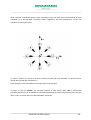
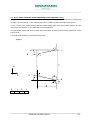
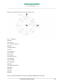
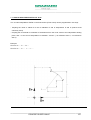
3.3 “G1 A…” PROGRAMMING WITH ANGLES
When using G1 instructions as well as the end of movement co-ordinates X and/or Z, besides radii or
chamfers on final points (R and ,C) the programmer can indicate the movement angle (A or ,A on
machines that have the motor driven back spindle option)
When programming the angle, value A can be positive or negative in a range from 0° to 360°. To define
the angle value, see the schematised figure imagining to position the “cross” with the centre on the first
point of the straight line. The angle of the line is determined by imagining to turn the cross zero (axis Z) in
the positive or negative direction to meet the straight line.
_____________________________________________________________________
CONCISE GUIDE FANUC
24
_____________________________________________________________________
The use of the A angle makes it possible to program just one final point matched to the movement angle
instead of two final points ( X e Z), or in certain conditions, to insert only the line angle without any final
co-ordinate.
Therefore there are two possibilities :
G1 X… A…
(final point in X and angle) with any chamfers (,C) or radii (R) on the final point
G1 A…
(angle only) with any chamfers (,C) or radii (R) on the final point
If only G1 A is used, the next block must absolutely contain both final co-ordinates (X, Z) and the angle
(A) with eventual chamfers (, C) or radius (R) on final point.
Example :
N48 G0 X0 Z2
N49 G1 Z0 F0.25
N50 G1 ,A90
N51 G1 X50 Z-20 A120
The value of angle A must be in centesimal degrees brought to the third decimal digit
Example :
N55 G1 ,A15.123
_____________________________________________________________________
CONCISE GUIDE FANUC
25
_____________________________________________________________________
Example of programming using the angles:
N48 G0 X0 Z2
N49 G1 Z0 F0.25
N50 X30 R5
N51 Z-60 ,A175 ,C3
N52 X50 ,A100
N53 G0 X200 Z200
_____________________________________________________________________
CONCISE GUIDE FANUC
26
_____________________________________________________________________
Example of programming using the angles:
N48 G0 X0 Z2
N49 G1 Z0 F0.25
N50 X40
N51 Z-7.1 ,A130
N52 X80 ,A150 R5
N53 Z-92 R4
N54 X140 ,A130 ,C2.65
N55 Z-130
N56 X160
N57 G0 X200 Z200
_____________________________________________________________________
CONCISE GUIDE FANUC
27
_____________________________________________________________________
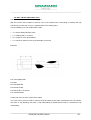
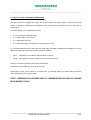
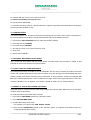
3.4 “G2 / G3” CIRCULAR INTERPOLATIONS
Functions G2 and G3 are programmed to make circle arcs in clockwise or anti-clockwise direction as
shown in the figure:
G3
G2
G3
The block with circular interpolation is programmed:
N24 G2 X… Z… R…
; Clockwise
N31 G3 X… Z… R…
; Anti-clockwise
N15 G2 X… Z… I… K…
; Clockwise
N18 G3 X… Z… I… K…
; Anti-clockwise
Or:
Where:
•
G2 / G3
=> Direction of circular interpolation
•
X
=> Co-ordinate of final point along axis X
•
Z
=> Co-ordinate of final point along axis Z
•
R
=> Radius of circular interpolation
•
I
=> Incremental distance of starting point at the radius centre
of the interpolation along axis X (radial value)
•
K
=>
Incremental distance of starting point radius at the centre
of the interpolation along axis Z
_____________________________________________________________________
CONCISE GUIDE FANUC
28
_____________________________________________________________________
I and K functions trend :
R
I
-K
Programming example :
22.4
19
R5
Ø44
Ø34
ø38
22.4
N5 ……
N5 …….
N6 G0 X38 Z3
N6 G0 X38 Z3
N7 G1 Z-19 F0.2
Or:
N7 G1 Z-19 F0.2
N8 G3 X44 Z-22.4 R5
N8 G3 X44 Z-22.4 1-2 K-3.4
N9 G1 Z-30
N9 G1 Z-30
N10 …….
N10 …….
G2 and G3 are modal functions and are cancelled by programming a linear movement G function (G0,
G1).
_____________________________________________________________________
CONCISE GUIDE FANUC
29
_____________________________________________________________________
3.5 “G4” AXIS PAUSE TIME
The G4 function controls a machine axes pause during the running of a cycle for a time, indicated in
seconds, that can be programmed with address U.
The G4 can be thus programmed:
N12 …….
N13 G4 U1
N14 …….
Where :
Activates the pause of the machine axes.
•
G4
=>
•
U
=> Defines the time of the axes pause in seconds.
Minimum value 0.001 seconds, maximum value 9999.999 seconds.
Function G4 is self deleting therefore it automatically disables in the block following the one where it is
located.
Always indicating the pause in seconds, it is also possible to have the pause in number of revolutions by
using this formula :
Seconds of pause for one spindle revolution = 60 / S (spindle speed in rpm)
Example:
If the spindle rotates at 300 rpm, the pause time for one revolution will be 60 / 300 = 0.2 seconds
If a pause is required equal to 3 rpm, write : G4 U0.6 (0.2 seconds x 3 rpm)
_____________________________________________________________________
CONCISE GUIDE FANUC
30
_____________________________________________________________________
3.6 “G95” FEED IN MM/REV
The G95 function selects the feed F in mm/rev. When this function is active the feed values will be
programmed as follows: F0.05, F0.15, F0.3, F0.5 and so forth. G95 is automatically activated when the
machine is switched on, therefore it is not necessary to specify its activation in the program. It is a modal
function and can be cancelled by programming code G94.
N4 ……
N5 G1 Z-30 F0.3
; Program with G95 (F= mm/rev.) present at power on
N6 ……
N7 ……
N8 ……
N9 G94
; Program with G94 (F= mm/min)
N10 G1 Z50 F500
N11 ……
N12 G95
; Program with G95 (F= mm/rev.)
N13 G1 Z-20 F0.2
N14 ……
3.7 “G94” FEED IN MM/MIN
The G94 function selects feed F in mm/min. When this function is active the feed values will be
programmed as follows: F50, F150, F500, F2000 and so forth. This function is used to perform
movements with work feed when the spindle is stationary, or when it is necessary to release the axis feed
from the spindle revolutions (e.g.: when milling with motor driven tools). G94 is a modal function and can
be cancelled by programming the code G95.
N5 G1 X… Z… F0.2
; Feed mm/rev. (present at power on)
N6 ……
N7 ……
N8 G94
; mm/min feed set
N9 G1 X… Z… F400
N10 ……
N11 ……
N12 G95
; mm/rev feed set
N13 G1 X… Z… F0.12
N14 ……
_____________________________________________________________________
CONCISE GUIDE FANUC
31
_____________________________________________________________________
3.8 “G97” FIXED REVOLUTIONS SPINDLE ROTATION
Function G97 prepares the spindle speed in revs/min (fixed revs) set by the code S. When this function is
active the programmed S value represents the actual number of revolutions per minute of the spindle.
(e.g.: S50, S160, S500, S1200, S3200, S5000 etc.). G97 is automatically activated when the control is
switched on, therefore it is not necessary to specify its activation in the program. It is a modal function
and can be cancelled by programming G96 (cutting speed set Vt [m/min.]).
This function is recommended when drilling and thread cutting, and is necessary for tapping.
Programming an S value with G97 active, and knowing the working diameter, the cutting speed value can
be calculated using this formula:
π xDx n
Vt =
Vt
π
D
n
=> cutting speed [m/min]
=> 3.14
=> work diameter
=> rpm
1000 => m to mm conversion
Where
1000
To calculate the cutting speed for machining performed at 1500 rpm on a diameter of 40:
Vt
= ? [m/min.]
π
= 3.14
D
= 40 mm
n
= 1500 rpm.
Vt =
3.14 x 40 x 1500
1000
= 188.4
A block containing G97 is programmed:
N4 T101
N5 G97 S1500 M4
N6 G0 X100 Z3 M8
Where:
•
G97
=> Spindle speed set in rpm
•
S1500
=> Number of spindle rpm
•
M4
=> Spindle direction of rotation
_____________________________________________________________________
CONCISE GUIDE FANUC
32
_____________________________________________________________________
3.9 “G96” CONSTANT CUTTING SPEED
G96 sets the spindle rotation indicated by the code S as constant cutting speed (m/min). With this
function active the programmed S value is the surface speed in metres per minute (e.g.: S80, S100, S120,
S200, S350 etc.), this function continuously updates the actual spindle revolutions according to the work
diameter, keeping the cutting speed constant. It is a modal function and can be cancelled by
programming G97 (rpm set).
During the turning operations (rough machining, finishing,) it is recommended to always use G96; the S
values to be set depend on the type of material, the type of tool, the machining method and so forth.
Example:
N4 T303
N5 G96 S180 M4
N6 G0 X100 Z3 M8
Programming an S value with G96 active the number of revs can be calculated according to the work
diameter, using this formula:
n=
Vt x 1000
πxD
Dove:
Vt
π
D
n
=> cutting speed [m/min]
=> 3.14
=> work diameter
=> rpm
1000 => m to mm conversion
To calculate the number of revs of machining performed at 150 m/min. on a diameter of 40:
Vt
= 150 [m/min.]
π
= 3.14
D
= 40 mm
n
= ? rpm.
n=
150 x 1000
3.14 x 40
= 1194
_____________________________________________________________________
CONCISE GUIDE FANUC
33
_____________________________________________________________________
A block containing G96 is programmed:
N4 ……
N5 G96 S150 M4
N6 ……
Where:
•
G96
=> Spindle speed set Vt [m/min]
•
S150
=> Cutting speed Vt [m/min]
•
M4
=> Spindle direction of rotation
3.10 “G92” SPINDLE REVOLUTION LIMITATIONS
Using the constant cutting speed (function G96) it is often necessary for technical reasons and safety
(type of collet chuck, size of workpiece, unbalancing, etc.), to set a limit to the spindle maximum rpm. For
example when facing or parting off, up to the centre of the workpiece the spindle speed tends to reach an
infinite value. Programming “G92 S2500” the spindle rotates with a constant cutting speed without,
however, exceeding the threshold of 2500 rpm.
Example:
N2 ……
N3 T404
N4 G92 S2000 ; spindle revolutions limited to a maximum of 2000
N5 G96 S150 M4
N6 G0 X100 Z3 M8
N7 ……
The limit set by G92 remains active until it is modified by a new setting of the same function, or it can be
deactivated by programming “G92 S0”.
Programming G97 (fixed revs) the spindle speed limit set with G92 active is deactivated, if there is a new
programming of G96 the spindle speed limit becomes active again.
At power on, if no value is specified for G92 S the spindle rotation speed will not be limited.
_____________________________________________________________________
CONCISE GUIDE FANUC
34
_____________________________________________________________________
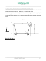
3.11 “G33” THREAD CUTTING MOVEMENTS
Function G33 is used for separate thread cutting movements.
In fact, G33 differs from G1 since the tool starts the working movement only when the control receives the
“spindle in position” signal from the encoder, which allows the tool to work in synchronisation with the
spindle (for this reason the NC offers the possibility to cut workpieces already threaded several times,
obviously without changing the gripping position).
The block with G33 may contain these instructions:
G33
final point (X or Z)
feed (F) starting angle (Q)
The starting angle of the thread cutting can be programmed with address Q from 0° to 360000°
(thousandths value).With the programming of a thread cutting starting angle it is possible to machine
multi-start threads without moving the starting point along axis Z. If no starting angle is programmed, the
NC assumes an angle of 0° as the starting value .
When machining threads, the axis and spindle trimmers are “frozen” at 100% of the programmed speed.
M30x1.25
25
Example:
N1 T1 (Thread cutting)
N2 G97 S1300 M3
N3 G0 X29.5 Z5 M8
N4 G33 Z-26 F1.25
N5 G0 X32
N6 Z5
N7 X29.2
N8 G33 Z-26 F1.25
N9 G0 X32
N10 Z5
N11 …..
Example of multi-thread machining :
_____________________________________________________________________
CONCISE GUIDE FANUC
35
_____________________________________________________________________
M30 x 2 w. 2 threads
25
N1 T1 (Thread cutting)
N2 G97 S1300 M3
N3 G0 X29.5 Z10 M8
N4 G33 Z-26 F4 Q0
N5 G0 X32
N6 Z10
N7 X29.5
N8 G33 Z-26 F4 Q180000
N9 G0 X32
N10 Z10
N11 X29.2
N12 G33 Z-26 F4 Q0
N13 G0 X32
N14 Z10
N15 X29.2
N16 G33 Z-26 F4 Q180000
N17 G0 X32
N18 Z10
N19 …..
N20 …..
_____________________________________________________________________
CONCISE GUIDE FANUC
36
_____________________________________________________________________
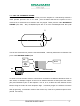
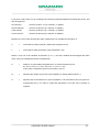
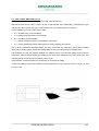
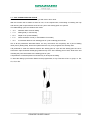
3.12 “G41”-“G42”- “G40” TOOL RADIUS OFFSET
All inserts for turning have the cutter edge rounded to a pre-defined radius, specified by the insert
manufacturer (e.g. 0.4; 0.8; 1.2 etc.). With the tool measurement a point is determined for movements
that is not on the insert profile, but is the intersection of the horizontal and vertical lines tangent to the
insert radius, as can be seen in the figure that follows.
Insert
This difference has no influence when turning cylindrical parts at 90° but causes an error when machining
conical and /or spherical parts, creating a profile that is not the same as that programmed. The value of
this error is proportional to the insert radius and assumes the maximum value in the case of a conical
profile at 45°:
Error = 0.412 x Insert radius
Insert
Turned
Profile
Programmed
profile
La tool radius offset è attivata e disattivata nel programma mediante le
seguenti funzioni:
_____________________________________________________________________
CONCISE GUIDE FANUC
37
_____________________________________________________________________
To use the Tool Radius Offset therefore means to enable 3 functions from the program:
G41
➨
Activate the Tool Radius Offset for a PIECE ON THE RIGHT as to the tool direction.
G42
➨
Activate the Tool Radius Offset for a PIECE ON THE LEFT as to the tool direction.
G40
➨
Deactivate the tool radius offset.
La Tool Radius Offset is usually only used in the finishing stages to obtain the correct profile. In fact, this
programming makes it possible to define exactly the profile specified on the drawing allowing the control to
automatically offset the errors caused by the insert position and radius. To work with offset the instructions
must be entered in the program to activate and deactivate the function and to supply the control with the
information regarding the insert (radius and orientation).
On machines fitted with the back spindle option the activation functions (G41 / G42) and deactivation
functions (G40), are applied as described in the previous diagram.
_____________________________________________________________________
CONCISE GUIDE FANUC
38
_____________________________________________________________________
When using the Tool Radius Offset it is also necessary to enter the value of the insert radius (R) and tool
orientation (T) in the tool table. The radius value is supplied by the insert manufacturer. For the tool
orientation see the figure below.
To make it simpler we can say that all the external left tools will have orientation T3 whereas all the
internal left tools will have orientation T2.
When assigning a tool orientation the insert geometry is not important.
At power on, after the RESET
key has been pressed, or after function M30, G40 is automatically
activated, furthermore it is not possible to activate and deactivate the radius offset inserting the instruction
(G42 or G41) in a block with a circular interpolation movement.
_____________________________________________________________________
CONCISE GUIDE FANUC
39
_____________________________________________________________________
Example of workpiece finishing with a tool radius 0.8:
N1 T101 (FINISHING)
N2 G92 S3000
N3 G96 S180 M4
N4 G0 X-2 Z3 M8
N5 G42 (Activation of Tool Radius Offset)
N6 G1 X0 Z0 F0.25
N7 X40 Z0
N8 Z-7.1 ,A130
N9 X80 ,A150 R5
N10 Z-92 R4
N11 X140 ,A130 ,C2.65
N12 Z-130
N13 X160
N14 G40 (Deactivation of tool Radius Offset)
N15 G0 X200 Z200 M5
N16 M30
Note: enter radius (R) 0.8 and tool orientation (T) 3 in the correctors table
_____________________________________________________________________
CONCISE GUIDE FANUC
40
_____________________________________________________________________
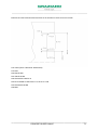
3.13 “G54 / G59” WORKPIECE ORIGINS
To be able to refer the tool movements to a fixed point on the workpiece to be machined. By means of a
certain operation procedure one or more fixed points are defined that allow the operator to have a
reference for the movements to be entered in the work program. These points are called “WORKPIECE
ORIGINS” (G54, G55, …G59). Usually these points are on the front of the workpiece near the spindle
rotating axis.
X
G54
Z
There is also a fixed reference point that cannot be modified , created by the machine manufacturer. This
point is called MACHINE ORIGIN (G53).
disk
turret
disk
origin
G53
Machine axis
This point is used as a primary reference point and as a consequence to define the Workpiece Origins. In
other words, the Workpiece Origins are found as the distance between the fixed point of the machine
(G53) and our reference point on the workpiece. There is, in fact, a table where the distances from the
Machine Origin are entered for each Workpiece Origin. In the work program it is sufficient to enter the
call-up for the required origin to make it active (example: G54) without any value.
When programming, movements in relation to the machine origin G53 are only allowed in rapid traverse
(with G0 movements).
_____________________________________________________________________
CONCISE GUIDE FANUC
41
_____________________________________________________________________
Origin G53 cannot be written alone in the block. It must always be coupled to X or Z co-ordinates which
identify the movement referred to the machine zero. This movement will always be carried out in rapid
traverse.
In the case of a more “traditional” use of the machine origin it is recommended to use an origin that can be
modified (e.g. G59) having X0 Z0 as value in the table
Example:
N2 ……
N3 T101
N4 G54 ; Workpiece origin activation
N5 G92 S2000
N6 G96 S150 M4
N7 G0 X…. Z…. M8
N8 ……
For the operating procedure of “Origin Measurement” and “Origin Modification”, see Chapter 15 of the
Concise Guide for Operator.
NOTE.
-
At power on the control automatically activates origin G54.
-
In the program the storable origin (G54–G59) is called up but its value (X,Z,B,C,A) is to be entered
directly in the origins table.
_____________________________________________________________________
CONCISE GUIDE FANUC
42
_____________________________________________________________________
3.14 “G52” ORIGIN TRANSFER BY PROGRAM
An alternative to the origin transfer by table is the direct origin transfer by program using instruction G52.
With the G52 function it is possible to move the reference point by program (e.g.: G54, G55 etc.).
G52 operates in absolute mode in relation to the last workpiece origin selected, with the movement values
inserted in the characters of address X and/or Z (e.g.: G52 X5 Z-10).
To cancel the origin transfer by program there are three possibilities :
machine reset
end of program instruction M30
instruction G52 X0 Z0 written in the program (procedure usually used).
Other functions cannot be inserted in the block where instruction G52 is programmed.
Example:
N2 ……
N3 G54
N4 ……
N5 G52 Z-10
Absolute origin transfer
N6 ……
N7 ……
N8 G52 Z0
Cancel origin transfer
N9 ……
NOTE. If other storable origins (G54 – G59) are programmed with the G52 function active, the NC
transfers from the value programmed in G52 to the new origin activated.
It is not possible to move the active origin in incremental mode using the G52 instruction. To get round this
problem, the G52 function can be repeated several times with different values
Example:
N1 G54
N2 ……
N3 G52 Z-10 (active origin moved by 10 mm)
N4 ……
N5 G52 Z-20
N6 ……
N7 G52 Z-30
N8 ……
N9 G52 Z0 (active origin transfer cancelled)
_____________________________________________________________________
CONCISE GUIDE FANUC
43
_____________________________________________________________________
3.15 “M134 / M135” PRECISE STOP
The tool passage from a block to another may happen in two ways:
-
in execution point to point
-
in continuous execution
These two ways of passage from a block to another can be enabled by two functions M, which are:
M134 execution point to point with deceleration at end of block.
With this function axes between the blocks execute a deceleration to reach the quote and then
restart.
In this way you’ll obtain a “precise” profile with live angles.
M135 Execution in continuous without deceleration at end of block.
With this function axes between a block and another don’t decelerate an so, if feed is elevated, you
have an error with rounding of edge.
This function is automatically active at power on.
We advise the use of function M134 to work profiles where a precise tolerance even on chamfers, cones
and fitting is required.
When programmed this function is disabled by function M135, with the reset or with a stop program (M0,
M1 or M30).
We advice to disable function M134 before executing a movement in rapid (GO).
_____________________________________________________________________
CONCISE GUIDE FANUC
44
_____________________________________________________________________
3.16 LIST OF MAIN “G” PREPARATORY FUNCTIONS
The list below indicates the main G preparatory functions used to program the FANUC numeric control.
G0 ➪ rapid axis linear movement.
G1 ➪ axis linear movement in work mode.
G2 ➪ clockwise circular interpolation.
G3 ➪ anticlockwise circular interpolation.
G4 ➪ stand-by.
G10 ➪ data entry from program.
G11 ➪ deletes the data entry from program mode
G17 ➪ selection of working surface X Y.
G18 ➪ selection of working surface Z X.
G19 ➪ selection of working surface Y Z.
G28 ➪ return to reference point (with axis C and axis A option).
G33 ➪ thread cutting movement.
G40 ➪ radius offset disable.
G41 ➪ tool radius offset with workpiece on right of profile.
G42 ➪ tool radius offset with workpiece on left of profile.
G52 ➪ absolute programmable origin transfer.
G53 ➪ enables transfers referring to machine origin.
G54 ➪ modifiable origin transfer.
G55 ➪ modifiable origin transfer.
G56 ➪ modifiable origin transfer.
G57 ➪ modifiable origin transfer.
G58 ➪ modifiable origin transfer.
G59 ➪ modifiable origin transfer.
G65 ➪ single macro instruction call up.
G66 ➪ modal macro-instruction call-up.
G67 ➪ delete modal macro-instruction call-up.
G70 ➪ finishing cycle.
G71 ➪ material removal by turning.
G72 ➪ material removal by facing.
G73 ➪ profile repetition.
G76 ➪ thread cutting cycle with several cuts.
G80 ➪ delete fixed front drilling cycle.
G83 ➪ fixed front drilling cycle.
_____________________________________________________________________
CONCISE GUIDE FANUC
45
_____________________________________________________________________
G84 ➪ fixed front tapping cycle (cannot be used with rotating tools).
G85 ➪
fixed cycle of frontal boring.
G87 ➪
fixed side drilling cycle.
G89 ➪
fixed side of lateral boring.
G90 ➪
programming with absolute co-ordinates.
G91 ➪
programming with incremental co-ordinates.
G92 ➪
spindle speed limitation.
G94 ➪
feed programming in mm/min.
G95 ➪
feed programming in mm/rev..
G96 ➪
constant cutting speed programming in m/min.
G97 ➪
fixed revolution spindle rotation programming in rpm.
G107 ➪ cylindrical interpolation.
G112 ➪ polar co-ordinates interpolation
G113 ➪ delete polar co-ordinates interpolation.
G174 ➪ radial grooves rough machining/pre-finishing cycle.
G175 ➪ radial grooves finishing cycle.
G176 ➪ axial grooves rough machining/pre-finishing cycle.
G177 ➪ axial grooves finishing cycle
_____________________________________________________________________
CONCISE GUIDE FANUC
46
_____________________________________________________________________
4.0 FIXED FANUC CYCLES
Fixed cycles are functions that simplify the ISO programming.
The most commonly used fixed cycles are described below.
4.1 “G71” MATERIAL REMOVAL BY TURNING
The “G71” function activates the material removal by turning cycle.
With this function the tool makes increments on axis X and turning on axis Z.
The material removal cycle in turning is always composed of two program blocks.
Example:
N17 …….
N18 G0 X.. Z.. .
N19 G71 U… R…
N20 G71 P… Q… U… W… F…
N21 G0/G1 X… Z…
N22 …
N23 … description of finished profile
N24 …
Where:
•
X
=> Start cycle co-ordinate along axis X
•
Z
=> Start cycle co-ordinate along axis Z
st
1 BLOCK OF G71
•
U
=> Depth of radial cut without sign.
•
R
=> Tool separation in return path at 45° value without sign
nd
2 BLOCK OF G71
•
P
=> Number of block where the rough machining profile starts
•
Q
=> Number of block where rough machining profile finishes
_____________________________________________________________________
CONCISE GUIDE FANUC
47
_____________________________________________________________________
•
U
=> Diametric machining allowance on axis X value indicated with sign
•
W
=> Machining allowance on axis Z value indicated with sign
•
F
=> Work feed in rough machining
In rapid traverse the tool reaches the X and Z values indicated in the block before the first G71 (these
values therefore determine the point where the tool will start to machine: X will be equal to the diameter of
the blank workpiece, Z will be the safety distance that facilitates the cut increment).
An increment takes place that is equal to the radial value indicated in parameter U of the first G71 block
(the increment can take place in rapid mode or work mode, depending on whether the profile description,
block after the second G71, starts with a G0 or a G1).
The tool performs the rough machining automatically making several cuts, going from the point indicated
in block P to the point indicated in block Q.
At the end of each cut the tool separates in rapid mode, by 45° by a radial value equal to that indicated in
parameter R and returns in rapid mode to the Z starting point.
After all the rough machining cuts have been made, the tool performs a pre-finishing cut to leave even
machining allowances (parameters U and W indicated with sign), and returns in rapid traverse to the
starting point. Value U (that determines the diametrical machining allowance along axis X) will be positive
for external machining and negative for internal machining. Parameter W (that determines the machining
allowance along axis Z) will be positive for machining from the tailstock toward the spindle and negative
for machining from the spindle toward the tailstock or for machining on the back spindle (on machines with
this option installed)
If the pre-finishing cut is not required, just program the block after the second G71, (block that starts the
finished profile) to contain both X and Z.
When running the cycle the tool works with the feed programmed in parameter F of the G71 cycle, any
feeds programmed in the profile description blocks are only activated during the finishing operation (see
G70 cycle further on).
NOTE. The G71 rough machining cycle does not use the tool radius offset (G41, G42, G40) which can, of
course, be activated in finishing (G70 cycle).
The finished profile of the workpiece cannot be managed in a sub-program, but only within the cycle itself.
_____________________________________________________________________
CONCISE GUIDE FANUC
48
_____________________________________________________________________
For overmetal U and W situation see the scheme below:
_____________________________________________________________________
CONCISE GUIDE FANUC
49
_____________________________________________________________________
Example of how to use the G71 cycle:
CHAMFERS 1.5 x 45°
O3434 (REMOVAL OF MATERIAL BY TURNING)
N1 T101
N2 G54
N3 G92 S3000
N4 G96 S200 M4
N5 G0 X140 Z3 M8
N6 G71 U3 R1
N7 G71 P8 Q19 U0 W0 F0.35
N8 G0 X26
N9 G1 Z0
N10 X30 ,C1.5
N11 Z-20 R2
N12 X50 ,A120 R3
N13 Z-78.5 R2
N14 X65 ,C1.5
N15 Z-110 R1.5
N16 X120 ,C1.5
N17 Z-130 R1.5
N18 X140 ,C1.5
_____________________________________________________________________
CONCISE GUIDE FANUC
50
_____________________________________________________________________
N19 Z-132
N20 G0 X200 Z200 M5
N21 M30
If in the profile there are shaded parts (decreasing profiles) proceed as follows:
- describe the shaded parts using the same functions as for monotone profiles, angles included
- the shaded parts cannot be more than 10
- the first profile description block (block after the second G71) must contain both X and Z
- remember that CNC, in machining of shaded parts, doesn’t consider the tool radius compensation.
_____________________________________________________________________
CONCISE GUIDE FANUC
51
_____________________________________________________________________
Example of how to use the G71 cycle with shaded parts :
O3435 (MATERIAL REMOVAL IN TURNING WITH SHADED PARTS)
N1 T606
N2 G54
N3 G92 S3000
N4 G96 S200 M4
N5 G0 X82 Z3 M8
N6 G71 U2 R1
N7 G71 P8 Q16 U0 W0 F0.35
N8 G0 X56 Z2
N9 G1 Z0
N10 X60 Z-2
N11 Z-30
N12 X40 ,A210
N13 Z-130
N14 X80 ,C2
N15 Z-133
N16 X83
N17 G0 X200 Z200 M5
N18 M30
_____________________________________________________________________
CONCISE GUIDE FANUC
52
_____________________________________________________________________
4.2 “G72” MATERIAL REMOVAL BY FACING
Function “G72” activates the material removal by facing cycle.
With this function the tool makes increments on axis Z and turning on axis X.
The material removal by facing cycle is always composed of two program blacks.
Example:
N17 …….
N18 G0 X.. Z.. .
N19 G72 W… R…
N20 G72 P… Q… U… W… F…
N21 G0/G1 X… Z…
N22 …
N23 … description of finished profile
N24 …
Where:
•
X
=> Start cycle co-ordinate along axis X
•
Z
=> Start cycle co-ordinate along axis Z
st
1 BLOCK OF G72
•
W
=> Depth of radial cut without sign.
•
R
=> Tool separation in return path at 45° value without sign
nd
2 BLOCK OF G72
•
P
=> Number of block where the rough machining profile starts
•
Q
=> Number of block where rough machining profile finishes
•
U
=> Diametric machining allowance on axis X value indicated with sign
•
W
=> Machining allowance on axis Z value indicated with sign
•
F
=> Work feed
_____________________________________________________________________
CONCISE GUIDE FANUC
53
_____________________________________________________________________
The tool, in rapid traverse, reaches the X and Z values indicated in the block before the first G72 (these
values thus determine the point where the tool will start machining: X will be equal to the rough workpiece
diameter plus a small safety margin that facilitates the cut increment, Z will be 0 if the workpiece is
already faced, or 1 or 2 if there is a machining allowance).
The increment will be equal to the value indicated in parameter W of the first G72 block (the increment
may be in rapid mode or working mode – this depends on whether the profile description in the block after
the second G72, starts with G0 or G1).
The tool makes the rough machining automatically performing a series of cuts going from one point
indicated in block P up to the point indicated in block Q.
At the end of each cut the tool separates by 45°, in rapid mode, for a radial value equal to that set in
parameter R and returns in rapid traverse to the Z starting point.
When all the rough machining cuts have been performed the tool makes a pre-finishing cut to leave even
machining allowances (parameters U and W indicated with sign), and returns in rapid traverse to the
starting point. Value U (which determines the diametrical machining allowance along axis X) will be
positive for external machining and negative for internal machining, parameter W (that determines the
machining allowance along axis Z) will be positive for machining from the back spindle toward the spindle,
and negative for spindle machining toward the back spindle or for machining on the back spindle (on
machines that have this option)
If the pre-finishing cut is not required it is sufficient to program the block after the second G72, block from
which the finished profile starts, containing in it both X and Z.
When performing the cycle, the tool works with the feed programmed in parameter F of cycle G72, any
feeds set in profile description blocks are only activated during the finishing operations.
NOTE. The rough machining cycle G72 does not include the use of the tool radius offsets (G41, G42,
G40) which can. of course, be activated for finishing (cycle G70).
The finished profile of the part cannot be managed in a sub-program, but only within the cycle itself.
_____________________________________________________________________
CONCISE GUIDE FANUC
54
_____________________________________________________________________
Example of how to use cycle G72:
CHAMFERS 2 x 45°
O3435 (REMOVAL OF MATERIAL BY FACING)
N1 T101
N2 G54
N3 G92 S3000
N4 G96 S200 M4
N5 G0 X122 Z0 M8
N6 G72 W2.5 R1
N7 G72 P8 Q18 F0.35
N8 G0 Z-47
N9 G1 X120
N10 Z-45 ,C2
N11 X80
N12 Z-25 ,C1.5
N13 X60
N14 Z-15
_____________________________________________________________________
CONCISE GUIDE FANUC
55
_____________________________________________________________________
N15 Z-10 ,A-60
N16 X30 R1.5
N17 Z0 ,C1.5
N18 X0
N19 G0 X200 Z200 M5
N20 M30
_____________________________________________________________________
CONCISE GUIDE FANUC
56
_____________________________________________________________________
4.3 “G73” PROFILE REPETITION
The “G73” function activates the profile repetition cycle.
With this function the defined profile can be repeated several times, moving it each time by a certain
distance. This cycle is most useful to work on workpieces coming from stamping, casting or a previous
rough machining.
The profile repetition cycle is always composed of two program blocks.
Example:
N17 …….
N18 G0 X.. Z.. .
N19 G73 U… W… R…
N20 G73 P… Q… U… W… F…
N21 G0/G1 X… Z…
N22 …
N23 … description of finished profile
N24 …
Where:
•
X
=> Start cycle co-ordinate along axis X
•
Z
=> Start cycle co-ordinate along axis Z
st
1 BLOCK OF G73
•
U
=> material to remove on x axe, radial value expressed with sign, (difference between
rough and worked)
•
W
=> material to remove on z axe, value expressed with sign, (difference between
rough and worked)
•
R
=> Number of profile repetitions
nd
2 BLOCK OF G73
•
P
=> Number of block where the rough machining profile starts
•
Q
=> Number of block where the rough machining profile finishes
•
U
=> Diametrical machining allowance on axis X , value with sign
W
•
F
=> Machining allowance on axis Z, value with sign
=> Work feed
_____________________________________________________________________
CONCISE GUIDE FANUC
57
_____________________________________________________________________
In rapid traverse the tool reaches the values of X and Z set in the block before the first G73 (thus these
values determine the point where the tool will start to work).
An increment takes place which is equal to the values set in parameters U and W of the first G73 and the
number of profile repetitions expressed in parameter R.
The tool makes a series of cuts going from the point set in block P up to the point set in block Q.
At the end of all the rough machining cuts the tool makes a pre-finishing cut to leave even machining
allowances (parameters U and W , with sign), and returns in rapid traverse to the starting point. Value U
(that determines the diametrical machining allowance along axis X) will be positive for external machining
and negative for internal machining, parameter W (that determines the machining allowance along axis Z)
will be positive for machining from the back spindle toward the spindle and negative for machining from
the spindle to the back spindle or for machining on the back spindle in machines with this option)
When performing the cycle the tool works with the feed programmed in parameter F of the G73 cycle. Any
feeds programmed in the profile description blocks will be activated only during finishing operations.
NOTE. the rough machining cycle G73 does not use the tool radius offsets (G41, G42, G40) which can,
of course, be activated for finishing (cycle G70).
The finished profile of the part cannot be managed in a sub-program, but only inside the cycle itself.
_____________________________________________________________________
CONCISE GUIDE FANUC
58
_____________________________________________________________________
Example of how to use cycle G73 :
O3436 (PROFILE REPETITION)
N1 T101
N2 G54
N3 G92 S3000
N4 G96 S200 M4
N5 G0 X120 Z10 M8
N6 G73 U3 W3 R4
N7 G73 P8 Q12 F0.35
N8 G0 X60 Z2
N9 G1 Z-20
N10 X80 Z-26
N11 Z-54 R10
N12 X100 Z-61
N13 G0 X200 Z200 M5
N14 M30
_____________________________________________________________________
CONCISE GUIDE FANUC
59
_____________________________________________________________________
4.4 “G70” FINISHING CYCLE
The “G70” function activates the finishing cycle. This function can be used after the three rough machining
cycles G71, G72 and G73.
The finishing cycle consists of just one block and can contain these codes:
•
P => Number of first block of the profile to be finished.
•
Q => Number of the last block of the profile to be finished.
•
F => Finish feed.
Before activating the finishing cycle G70 the tool must be positioned in the same point where the rough
machining cycle G71, G72 or G73 started.
At the end of the finishing cycle the tool returns to the starting point and the NC runs the next block
There are two possibilities for the feed used in the finishing stage:
- if the whole profile is to be machined with the same feed, just specify this value inside block G70 (with
parameter F)
- if various feeds are to be used on the profile, these must be specified in the profile rough machining
(these feeds will be ignored in the rough machining but activated in the finishing stage)
_____________________________________________________________________
CONCISE GUIDE FANUC
60
_____________________________________________________________________
Example of how to use cycle G70:
CHAMFERS 1.5 x 45°
O3437 (PROFILE ROUGH MACHINING AND FINISHING)
N1 T101
N2 G54
N3 G92 S3000
N4 G96 S200 M4
N5 G0 X140 Z3 M8
N6 G71 U3 R1
N7 G71 P8 Q19 U0.5 W0.1 F0.35
N8 G0 X26
N9 G1 Z0
N10 X30 ,C1.5
N11 Z-20 R2
N12 X50 ,A120 R3
_____________________________________________________________________
CONCISE GUIDE FANUC
61
_____________________________________________________________________
N13 Z-78.5 R2
N14 X65 ,C1.5
N15 Z-110 R1.5
N16 X120 ,C1.5
N17 Z-130 R1.5
N18 X140 ,C1.5
N19 Z-132
N20 G0 X200 Z200
N21 T202
N22 G54
N23 G92 S3000
N24 G96 S200 M4
N25 G0 X140 Z3 M8
N26 G70 P8 Q19 F0.15
N27 G0 X200 Z200 M5
N28 M30
_____________________________________________________________________
CONCISE GUIDE FANUC
62
_____________________________________________________________________
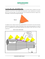
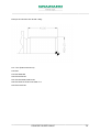
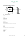
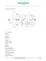
4.5 “G174” RADIAL GROOVES ROUGH MACHINING/PRE-FINISHING CYCLE
Function G174 activates the rough machining and pre-finishing cycle for grooves on outer and inner
diameters, performed by a parting tool with less width at the bottom of the groove.
To run a G174 cycle the tool must be positioned with the reference edge on the start cycle point (tool
reset on left edge), at a distance of a diametrical millimetre from the part to be machined.
The feed speed used is that active when the operation is called up and must be specified in a block prior
to G174.
Figure 1
4
1
X
H
Z
3
4
0/8
3
0/4
2
0/2
2
1
0/1
D
_____________________________________________________________________
CONCISE GUIDE FANUC
63
_____________________________________________________________________
C
R
TOOL RESET
The insert radius of the tool used must be specified in the correctors table.
G174 must be programmed as follows:
N...G174 A.. B.. C.. U/X.. W/Z.. Y.. H.. K.. Q.. D.. (F..) (L..) (P..) (R..) (S..)
Where:
G174
=
Activates the rough machining and pre-finishing cycle for the outer and inner radial
grooves.
A..
=
Angle of groove right-hand wall (in positive direction of axis Z)
B..
=
Angle of groove left-hand wall.
These angles are always positive and have a value from 0 to 89.999 degrees. When the
assigned value is 0, this means that the walls are vertical.
C..
=
Tool width , always positive value,(radius R and orientation type 3 must be specified in
offset table as radius compensation is activated automatically).
U/X..
=
U indicates the depth of the groove, X indicates the value of the bottom of the groove
- specify one or the other - :
If U < 0 = external groove
If U > 0 = internal groove
If X < value of starting point X = external groove
If X > value of starting point X = internal groove
_____________________________________________________________________
CONCISE GUIDE FANUC
64
_____________________________________________________________________
W/Z..
=
W groove width, Z last point of groove – specify one or the other -:
If W<0 the groove machining is made from right to left of the workpiece.
If W>0 the groove machining is made from left to right of the workpiece.
If Z < the starting point value, machining is made from right to left of the workpiece
(toward Z negative).
If Z > the starting point value, machining is made from left to right of the workpiece
(toward Z positive).
Y*..
=
Linking radius or dimension of chamfer 1 (upper external)
H*..
=
Linking radius or dimension of chamfer 2 (upper internal)
K*..
=
Linking radius or dimension of chamfer 3 (lower internal)
Q*..
=
Linking radius or dimension of chamfer 4 (lower external)
If Y,H,K,Q, are omitted, the cycles considers them as 0.
This means that they will be eliminated from the machining (sharp edge).
D..
=
Defines the type of profile (chamfer or radius) in points 1,2,3,4 (figure 1).
Bit 3 Bit 2 Bit 1 Bit 0
0/8
0/4
0/2
8
4
2
0/1
Binary example of number D
1
D can assume a value from 0 to 15 according to the elements (chamfers/radii) that constitute the groove
and how they are arranged.
First element
: may assume value 0-1 (0= Chamfer, 1= Radius)
Second element
: may assume value 0-2 (0= Chamfer, 2= Radius)
Third element
: may assume value 0-4 (0= Chamfer, 4= Radius)
Fourth element
: may assume value 0-8 (0= Chamfer, 8= Radius)
On the basis of the sum of the elements the value is calculated for parameter D (see figure 1).
F..
=
overmetal on end of groove(vertical), radial value and expressed in mm.
_____________________________________________________________________
CONCISE GUIDE FANUC
65
_____________________________________________________________________
L..
=
overmetal on groove’s sides value expressed in mm.
NOTE: if only one of the two variables (F or L) is specified, the other variable will be assigned the same
value. If they are omitted both are considered null.
P..
= Depth of cut (it must always be more than 0, radial value expressed in mm.).The distance
between on cut and another is 0.2 mm.If omitted the machining is executed in one cut.
R..
=
Specifies how many grooves (cycle repetition); if omitted , default value is 1.
S..
=
Specifies the centre distance for groove repetition. It can be omitted if only one groove is
programmed (R=1). The value is expressed in mm and may be positive or negative.
Example of rough machining and pre-finishing of a radial groove with a tool having a width of 3 mm:
N18 T303 (TOOL FOR RADIAL GROOVES)
N19 G54
N20 G92 S1500
N21 G96 S100 M4
N22 G0 X101 Z-30 M8 F0.12
N23 G174 A5 B8 C3 X60 Z-80 Y1 Q1 H1.5 K1.5 D6
N24 G0 X200 Z100 M5
N25 M30
_____________________________________________________________________
CONCISE GUIDE FANUC
66
_____________________________________________________________________
4.6 “G176” AXIAL GROOVES ROUGH MACHINING/PRE-FINISHING CYCLE
The G176 function activates the rough machining and pre-finishing cycle for axial grooves, working from
the right or the left (see fig. 1) with a parting tool having a width less than the bottom of the groove
To run a G176 cycle, position the tool with the reference edge (tool reset on the bottom edge)on the start
cycle point, at a distance of 0.5 millimetres from the workpiece.
The feed speed used is that which is active when the function is called up and must be specified in a block
prior to G176.
The G176 cycle disables the tool radius offset (G40)
Figure 1
1
2
H
X
3
Z
4
4
0/8
3
2
0/4 0/2
D
1
0/1
_____________________________________________________________________
CONCISE GUIDE FANUC
67
_____________________________________________________________________
Radius specified in the correctors table for the tool used.
C
R
Tool reset
Function G176 has to be programmed as follows:
N...G176 A.. B.. C.. U/X.. W/Z.. Y.. H.. K.. Q.. D.. (F..) (L..) (P..) (R..) (S..)
Where:
G176
=
Activates the rough machining and pre-finish cycle for right and left axial grooves.
_____________________________________________________________________
CONCISE GUIDE FANUC
68
_____________________________________________________________________
A..
=
Angle of groove high wall (in axis X positive direction)
B..
=
Angle of groove low wall.
These angles are always positive and have a value from 0 to 89.999 degrees. When the
assigned value is 0 , this means the walls are horizontal.
C..
=
Tool width, always positive value,(r radius and orientation T3 must be specified on table
offset as it’s automatically activated the radius compensation).
U/X..
=
U width of groove, X last point of groove – specify one or the other - :
If U < 0 the groove machining takes place from top to bottom.
If U > 0 the groove machining takes place from bottom to top.
If X < of the start point value, machining takes place from top to bottom of the workpiece
(X negative direction).
If X > of the start point value, machining takes place from bottom to top of the workpiece
(X positive direction).
W/Z..
=
W indicates the depth of the groove, Z indicates the groove bottom measurement
- specify one or the other - :
If W < 0 = concave groove to left (Z negative direction)
If W > 0 = concave groove to right(Z positive direction)
If Z < of X start point value = concave groove to left
If Z > of X start point value = concave groove to right
Y*..
=
Linking radius or chamfer dimension 1 (upper external))
H*..
=
Linking radius or chamfer dimension 2 (upper internal)
K*..
=
Linking radius or chamfer dimension 3 (lower internal)
Q*..
=
Linking radius or chamfer dimension 4 (lower external)
If Y,H,K,Q, are omitted, the cycle considers them as 0.
This means that they will be ignored when machining (sharp edge).
D..
=
Defines the type of profile (if chamfer or radius) in points 1,2,3,4 (figure 1).
Bit 3 Bit 2 Bit 1 Bit 0
0/8
0/4
0/2
8
4
2
0/1
Binary example of number D
1
_____________________________________________________________________
CONCISE GUIDE FANUC
69
_____________________________________________________________________
D can have a value from 0 to 15 according to the elements (chamfers/radii) that constitute the groove, and
their arrangement.
First element
: can have a value 0-1 (0= Chamfer, 1= Radius)
Second element
: can have a value 0-2 (0= Chamfer, 2= Radius)
Third element
: can have a value 0-4 (0= Chamfer, 4= Radius)
Fourth element
: can have a value 0-8 (0= Chamfer, 8= Radius)
Based on the sum of the elements the value of parameter D is calculated D (see figure 1).
F..
=
Overmetal on bottom (vertical), radial value expressed in mm.
L..
=
Overmetal on sides (horizontal), value expressed in mm.
NOTE: if only one of the variables is specified (F or L) , the other variable will be assigned the same
value. If they are omitted both will be considered null.
P..
=
Depth of cut (must always be greater than 0). Value expressed in mm.
The distance between one block and another is equal to 0.2 mm.
If this value is omitted the groove is executed in one cut.
R..
=
Specifies the number of grooves (cycle repetition); if omitted, default value is 1.
S..
=
Specifies the centre distance for groove repetition. It can be omitted if only one groove is
programmed (R=1). The value is radial and expressed in mm and can be positive or
negative.
_____________________________________________________________________
CONCISE GUIDE FANUC
70
_____________________________________________________________________
Example of rough machining and pre-finish of an axial groove using a tool 3 mm wide:
N18 T909 (TOOL FOR AXIAL GROOVES)
N19 G54
N20 G92 S1500
N21 G96 S100 M4
N22 G0 X30 Z0.5 M8 F0.12
N23 G176 A5 B8 C3 X80 Z-20 Y1 Q1 H1.5 K1.5 D6
N24 G0 X200 Z100 M5
N25 M30
_____________________________________________________________________
CONCISE GUIDE FANUC
71
_____________________________________________________________________
4.7 “G175” / “G177” FINISHING CYCLE FOR RADIAL/AXIAL GROOVES
Functions G175 and G177 activate the finishing cycle for radial grooves (on outer and inner diameters)
and axial grooves (cut from right to left of the workpiece).
Only function G175 is described here; the description is also valid for cycle G177 (for which the rough
machining cycle is G176).
The tool position and reset follows the rules already described for rough machining cycle G174 which
should be consulted for further details.
The feed speed used is that which is active when the function is called up, and must be specified in a
block prior to G175.
The G175 cycle disables the tool radius offset (G40).
The parameters used are the same as for cycle G174, except for parameters F, L, P which are not used.
To activate the finishing cycle there are two syntaxes that can be used:
N...G175 A.. B.. C.. U/X.. W/Z.. Y.. H.. K.. Q.. D.. (R..) (S..)
In this case all the parameters are specified (see cycle G174).
N...G175 (C..)
In this second case all the parameters indicated in the last rough machining cycle that was run are used
except, (if specified) parameter C (tool width).
In both cases the corrector and the radius of the cutter used by the cycle are those active when G175 is
run.
_____________________________________________________________________
CONCISE GUIDE FANUC
72
_____________________________________________________________________
Example of rough machining and finish on a radial groove with a tool 3 mm wide:
N18 T303 (TOOL FOR RADIAL GROOVES)
N19 G54
N20 G92 S1500
N21 G96 S100 M4
N22 G0 X101 Z-30 M8 F0.12
N23 G174 A5 B8 C3 X60 Z-80 Y1 Q1 H1.5 K1.5 D6 F0.4 L0.1
N24 G175
N24 G0 X200 Z100 M5
N25 M30
_____________________________________________________________________
CONCISE GUIDE FANUC
73
_____________________________________________________________________
If the grooves cycle is not programmed correctly, the following alarms may be generated:
All 3000:
Parameter X or U missing:
The value for parameter X or U has been omitted.
All 3001:
Parameter Z or W missing:
The value for parameter Z or W has been omitted.
All 3002:
Parameter C not correct:
The value for parameter C has been omitted or the value
is less than or equal to 0.
All 3003:
Wrong tool data:
The tool radius programmed is larger than the tool width
*All 3004:
Slot geometry error:
The slot geometry is not correct.
All 3005:
Lower right radius error:
divided by 2.
The tool radius programmed is larger than the lower right
radius (only for external grooves).
All 3006:
Upper right radius error:
The tool radius programmed is larger than the upper
right radius (only for internal grooves).
All 3007:
Upper left radius error:
The tool radius programmed is larger than the upper left
radius (right groove bore).
All 3008:
Upper right radius error::
The tool radius programmed is larger than the upper right
radius (left groove bore).
All 3009:
Lower left radius error:
The tool radius programmed is larger than the lower left
radius (only for external grooves).
All 3010:
Upper left radius error:
The tool radius programmed is larger than the upper left
radius (only for internal grooves).
All 3011:
Lower left radius error::
The tool radius programmed is larger than the lower left
radius (right groove bore)
All 3008:
Upper right radius error::
The tool radius programmed is larger than the upper right
radius (left groove bore).
All 3012:
Lower right radius error:
The tool radius programmed is larger than the lower right
radius (left groove bore).
*All 3013:
Lower right chamfer error:
Lower right chamfer too small in relation to programmed
tool radius (only external grooves).
*All 3014:
Upper right chamfer error:
Upper right chamfer too small in relation to programmed
tool radius (only internal grooves).
_____________________________________________________________________
CONCISE GUIDE FANUC
74
_____________________________________________________________________
*All 3015:
Upper left chamfer error:
Upper left chamfer too small in relation to programmed
tool radius (right groove bore).
*All 3016:
Upper right chamfer error:
Upper right chamfer too small in relation to programmed
tool radius (left groove bore).
*All 3017:
Lower left chamfer error:
Lower left chamfer too small in relation to programmed
tool radius (only external grooves).
*All 3018:
Upper left chamfer error:
Upper left chamfer too small in relation to programmed
tool radius (only internal grooves).
*All 3019:
Lower left chamfer error:
Lower left chamfer too small in relation to programmed
tool radius (right groove bore).
*All 3020:
Lower right chamfer error:
Lower right chamfer too small in relation to programmed
tool radius (left groove bore).
*All 3021:
Tool too big: Width of tool larger than the slot width or the tool base is larger than the
bottom of the slot or with the tool dimensions programmed it is not possible to reach the bottom of the slot.
All 3022:
Parameter P error: A value has been programmed for parameter P which is negative or
equal to 0.
All 3023:
Parameter F or L negative: A negative value has been programmed for parameter F or L
for machining allowance.
All 3024:
Parameter Y H K Q negative
A negative value has been programmed for one or more
of the parameters Y H K Q.
All 3025:
Parameters A B error: A value has been programmed angle A and/or B which is less than 0
or greater than 90 degrees.
All 3026:
Parameter R negative: A negative value has been programmed for the number of groove
repetitions (if this value is 0 no groove is cut).
All 3027:
Parameter S error: A number of grooves have been programmed which is greater than one,
but no value (different from 0) has been set for the centre distance between grooves.
* These errors may be caused by an excessive machining allowance value in relation to the slot
dimensions.
_____________________________________________________________________
CONCISE GUIDE FANUC
75
_____________________________________________________________________
4.8 “G76” THREAD CUTTING CYCLE IN SEVERAL CUTS
Function “G76” activates the thread cutting cycle in several cuts.
This function can be used for external and internal thread cutting.
The thread cutting cycle in several cuts is always composed of two program blocks.
Example:
N17 …….
N18 G0 X.. Z.. .
N19 G76 P… Q… R…
N20 G76 X… Z… R… P… Q… F…
N21 G0 X… Z…
Where:
§ X => Cycle start co-ordinate along axis X (it is also the value reached by the tool in separation at the
end of each cut)
• Z => Cycle start co-ordinate along axis Z
st
1
BLOCK OF G76
•
P => Parameter P always has 6 digits (3 pairs of numbers)
st
1 pair : number of finishing cuts (value from 00 to 99, always two digits)
E.g.
00 no finishing cut
01 one finishing cut
02 two finishing cuts
nd
2 pair : tapered exit from thread (value from 00 to 99, always two digits)
E.g.
00 vertical exit from thread
05 tapered exit from thread 0.5 times the cut (value equal to half the cut)
10 tapered exit from thread 1 time the cut (value equal to cut)
_____________________________________________________________________
CONCISE GUIDE FANUC
76
_____________________________________________________________________
rd
3
pair : thread cut angle (value of two digits, only 6 selections 00,29,30,55,60,80)
E.g.
00 for square thread cutting
55 for Whitworth thread cutting
60 for metric thread cutting
If threads are to be cut with an angle that differs from the 6 selections available, use value 00
In brief : P010060 (1 idle traverse, vertical exit at end of thread , thread with angle of 60°)
•
Q => Minimum cut depth (in thousandths)
E.g.
•
Q100=0.1mm.
R => Depth of finishing cut (radial, in mm)
E.g.
R0.02=0.02mm.
nd
2 BLOCK OF G76
• X => Bottom of thread diameter
• Z => End of thread absolute co-ordinate
• R => Taper of thread cut (radial difference between starting thread cut diameter and diameter at end
of thread cutting). The value must be indicated with a sign. For cylindrical thread cutting
parameter R is not indicated.
R=(START OF THREAD DIAMETER – END OF THREAD DIAMETER) / 2
•
P => Radial height of thread (in thousandths and without sign)
The value set for P depends on the type of thread cut and can be:
P=613 for Cut for ISO metric thread
P=640 for Cut for Whitworth thread DIN 11
P=500 for Cut for square thread
Thus : P1226 (for an ISO metric thread pitch 2)
•
Q => Radial depth of first cut (in thousandths)
E.g.
•
Q250=0.25mm.
F => Thread pitch (in mm.)
E.g.
F1.5 for thread with 1.5 mm pitch.
_____________________________________________________________________
CONCISE GUIDE FANUC
77
_____________________________________________________________________
Example of external metric thread cutting :
N17 T101 (External thread cut)
N18 G54
N19 G97 S800 M3
N20 G0 X32 Z6 M8
N21 G76 P010060 Q100 R0.02
N22 G76 X28.161 Z-50 P919 Q250 F1.5
N23 G0 X150 Z100
_____________________________________________________________________
CONCISE GUIDE FANUC
78
_____________________________________________________________________
Example of internal metric thread cut :
N17 T101 (Internal thread cut)
N18 G54
N19 G97 S800 M3
N20 G0 X25 Z6 M8
N21 G76 P010060 Q100 R0.02
N22 G76 X30 Z-40 P919 Q250 F1.5
N23 G0 X150 Z100
_____________________________________________________________________
CONCISE GUIDE FANUC
79
_____________________________________________________________________
Example of external tapered thread cut 1” NPT (pitch 14 threads / inch) :
N17 T101 (Taper thread cut)
N18 G54
N19 G97 S800 M3
N20 G0 X33 Z6 M8
N21 G76 P010060 Q100 R0.02
N22 G76 X29.588 Z-17.343 P1161 Q250 F1.814 R-0..729
N23 G0 X150 Z100
To machine the tapered thread cut it is important to remember:
- Pitch F = 25.4 (comparison between mm and inches) / 14 (n° threads / inch) = 1.814 mm
- P is calculated by multiplying the pitch by 640 (1.814 x 640 = 1161)
- End of thread X refers to the final diameter 31.91 – [(0.64 x 1.814) x2] = 29.588
-
The starting diameter to calculate R is that relating to the starting Z (in the example Z6); in this case
making the calculation with the aid of trigonometry, the result is X29.367,
-
Therefore
R
Will
be
(30.451-31.91):2=-0.729
_____________________________________________________________________
CONCISE GUIDE FANUC
80
_____________________________________________________________________
4.9 “G83” FRONT DRILLING CYCLE
Function “G83” activates the front drilling cycle.
With this function the bit makes a series of cuts, of the required size, undercutting or breaking the chip
and returning, at the end of cycle, in rapid traverse to the starting point.
The front drilling cycle can contain these codes:
• Z => End of drilling absolute value
• F => Drilling feed ( in mm/rev.)
• Q => Depth of cut (in thousandths)
• P => Pause on bottom of hole (in thousandths of second)
Example:
N12 T303 (DRILLING)
N13 G54
N14 G97 S800 M3
N15 G0 X0 Z5 M8
N16 G83 Z-50 F0.12 Q1000
N17 G0 X200 Z200
Codes Q and P if not used, need not be written.
This cycle can be used to break or undercut chips according to the value of parameter 5101 bit 2 (RTR),
with value 0 chip breaking, with value 1 chip undercutting, by default this bit is set to 1 therefore for chip
undercutting.
_____________________________________________________________________
CONCISE GUIDE FANUC
81
_____________________________________________________________________
It should also be remembered that parameter 5114 determines:
-
with chip undercutting: the distance at which the drill is to stop in relation to the last point reached,
when re-entering the hole after undercutting.
-
with chip breakage: by how much the drill is to come backward between one drilling cut and the next
To cancel the drilling cycle it is necessary to program function G80 or any G function in group 01,
therefore G0, G1, G2, or G3.
NOTE: On all Graziano Spa machine models the axial tool resetting (tapping drills, cutters etc.) is made
only along axis Z but it is necessary to enter zero in the X location of the tool table for the tool used (See
Concise Guide for Operator, paragraph 3.2)
_____________________________________________________________________
CONCISE GUIDE FANUC
82
_____________________________________________________________________
4.10 “G84” FRONT TAPPING CYCLE
THIS CYCLE IS NOT VALID FOR TAPPING WITH MOTOR DRIVEN TOOLS
FOR TAPPING WITH MOTOR DRIVEN TOOLS SEE FUNCTIONS P9103 AND P9104
Function “G84” activates the front tapping cycle.
With this function the tapping drill enters with a feed equal to the tapping pitch, feed reduction and spindle
revs to reach the end point of the tapping simultaneously, reverse spindle rotation,
simultaneous
acceleration of spindle and axis and return to starting point.
The front drilling cycle can contain these codes:
•
Z => End of tapping absolute value
•
F => Tapping pitch (in mm/rev.)
Example:
N12 T404 (TAPPING M10 x 1.5)
N13 G54
N14 G97 S300 M3
N15 G0 X0 Z5 M8
N16 G84 Z-35 F1.5
N17 G80
N18 G0 X200 Z200
_____________________________________________________________________
CONCISE GUIDE FANUC
83
_____________________________________________________________________
This cycle can only be used for right-hand tapping, therefore with entry in direction M3 and coming out in
direction M4. If a left-hand tapping is required, two parameter values have to be changed :parameter 5112
(entry direction of rotation, usually 3) and parameter 5113 (direction of rotation coming out, usually 4) To
execute a tapping on backspindle it’s necessary to change the value of two parameters: parameter 5112
(rotation direction in entry normally 204) and the parameter 5113 (rotation direction in exit normally 203).
At the end of this operation you need to recall the right values of the two parameters 5112 value 3 and
5113 value 4 already inserted by default.
To cancel the tapping cycle it is necessary to program function G80 or any G function in group 01,
therefore G0, G1, G2, or G3.
This cycle can be used both for tapping with offset and for tapping without offset (rigid).
When using rigid tapping, function M29 must be set in the block prior to the G84 cycle.
Example of rigid tapping:
N12 T404 (RIGID TAPPING M10 x 1.5)
N13 G54
N14 G97 S300 M3
N15 G0 X0 Z5 M8
N16 M29 (RIGID TAPPING ACTIVATION)
N17 G84 Z-35 F1.5
N18 G80
N19 G0 X200 Z200
To cancel the rigid tapping cycle, function G80 or any G function of group 01, therefore G0, G1, G2, or G3
must be programmed.
_____________________________________________________________________
CONCISE GUIDE FANUC
84
_____________________________________________________________________
5.0 SUB-PROGRAMS / PARAMETRIC PROGRAMMING
Sub-programs are useful to repeat the same operation several times, using inside the program the same
functions and co-ordinates already known to the operator
With parametric programming, variable values (parameters or
variables #) can be attributed to the
program codes instead of fixed values (numeric values). A value can be assigned to a variable through
the program, from the MDI window, or inserting it in the variables table.
A variable is programmed with address # followed by a number
5.1 “M98” “M99” USE OF SUB-PROGRAMS
A program can be divided into main program and sub-programs.
Usually the NC operates under the control of the main program, but when an instruction is found that calls
up a sub-program the control passes over to the sub-program. When an instruction to return to the main
program is found, the control returns to the main program.
Sub-programs can be used when there are fixed repetitive sequences, simplifying the programming. A
sub-program can be called up by the main program. A sub-program that has been called can, in its turn,
call up another sub-program. Sub-program call-ups can be nested in up to four levels, as shown on the
next page:
_____________________________________________________________________
CONCISE GUIDE FANUC
85
_____________________________________________________________________
MAIN
PROGRAM
O1
…
…
…
…
…
M98 P8001
…
…
…
…
M30
SUBPROGRAM
O8001
…
…
…
…
…
M98 P8002
…
…
…
…
M99
Level 1
SUBPROGRAM
O8002
…
…
…
…
…
M98 P8003
…
…
…
…
M99
Level 2
SUBPROGRAM
O8003
…
…
…
…
…
…
…
…
…
…
M99
Level 3
A sub-program is a normal program that ends with function M99. The same functions can be used inside
the sub-program as used in main programs (e.g. fixed cycles, geometric functions etc.)
To simplify their use, we suggest that sub-programs are given names from O8001 to O8999 (main
programs go from O1 to O8000)
A sub-program is run when it is called by the main program or by another sub-program.
To call up a sub-program, write:
M98 P
OOOO
OOOO
Number
name of
Repetition
sub-program
(max 9999)
When the number of repetitions is omitted the NC assumes a value of 1
Example : sub-program 8003 is to be repeated 6 times consecutively
M98 P68003
Instruction “M99” that closes the sub-program is used to return to the main program (or to the subprogram) in the block that immediately follows the running of the sub-program.
_____________________________________________________________________
CONCISE GUIDE FANUC
86
_____________________________________________________________________
If it is required to return from the sub-program to a pre-defined block and not to the block that immediately
follows the one in which it has been run, add the pre-defined block to M99, preceded by the letter P.
MAIN
PROGRAM
N10
N20
N30
N40
N50
N60
M98P8003
N70
N80
N90
N100
N110 M30
SUBPROGRAM
O8003
N10
N20
N30
N40
N50
N60
N70
N80
N90
N100 M99P80
M30
After the sub-program has run, the NC returns in the main program at block N80
Function M99 (which usually closes a sub-program) can be used
also in the main program as an
unconditioned skip (to skip always to a pre-defined block)
O1 (MAIN PROGRAM)
N10
N20
N30 /M99 P70 (USED TO OPTIONALLY SKIP THE PARTS OF THE PROGRAM FROM BLOCK 30 TO
BLOCK 70, SEE USE OF BARRED BLOCK)
N40
N50
N60
N70
N80
N90
N100 M30
_____________________________________________________________________
CONCISE GUIDE FANUC
87
_____________________________________________________________________
Or to repeat continually a part of the program
O2 (MAIN PROGRAM)
N10
N20
N30
N40
N50
N60
N70
N80
N90 M99 (SKIP TO FIRST BLOCK AND CONTINUE REPEATING THE PROGRAM)
N100 M30
_____________________________________________________________________
CONCISE GUIDE FANUC
88
_____________________________________________________________________
5.2 PARAMETRIC PROGRAMMING
Parametric programming uses variables, arithmetical instructions and conditioned skip instructions. In this
way programs for general use can be developed, or they can be personalised for specific customer
requirements.
VARIABLES
There are four types of variables:
From #1 to #33
LOCAL VARIABLES
These can only be used inside a macro and not
shared with other macros. At power on
the
content of these macros is nil because they are
volatile.
From #100 to #149
COMMON VARIABLES
These can be shared with other
macros. At power on the content of these
macros is nil because they are volatile
From #500 to #999
COMMON VARIABLES
These are like the variables from #100 to #149
with the difference that they are stable, they
hold their content even with the machine
switched off.
From #1000 to #….
SYSTEM VARIABLES
Used to read and write NC data, such as
position of tool, of the axis and the tool
correction values etc.
Since genuary 2001 common variables “fixed” by the customers, for parametric programming, are
those which range from #510 to #699; as the others are used by Graziano SPA for specific
operations.
_____________________________________________________________________
CONCISE GUIDE FANUC
89
_____________________________________________________________________
ARITHMETIC OPERATIONS
There are ten types of arithmetical operations available:
1 Variable definition and replacement
Example:
#101=1005
#101=#110
#101=-#112
2 addition
Example:
#101=#110+#111
3 subtraction
Example:
#101=#110-#111
4 multiplication
Example:
#101=#110*#111 or #101=#110*7
5 division
Example:
#101=#110/#111 or #101=#110/7
6 square root
Example:
#101=SQRT[#110] or #101=SQRT[5]
_____________________________________________________________________
CONCISE GUIDE FANUC
90
_____________________________________________________________________
7 sine
Example :
#101=SIN[#110] or #101=SIN[30]
8 cosine
Example:
#101=COS[#110] or #101=COS[30]
9 tangent
Example:
#101=TAN[#110] or #101=TAN[30]
10 arc. cot.
Example:
#101=ATAN[#110]/ [#103]
CONDITIONED AND UNCONDITIONED SKIP INSTRUCTIONS
There are seven types of conditioned and unconditioned skip instructions:
1 unconditioned skip
Example:
GOTO1000 (skip to block N1000)
2 conditioned skip if the same
Example:
IF[#101 EQ #102] GOTO1000
(skip to block N1000 if parameter #101 is the same as
parameter #102, if the two parameters are different
the program passes to the next block)
_____________________________________________________________________
CONCISE GUIDE FANUC
91
_____________________________________________________________________
3 conditioned skip if different
Example:
IF[#101 NE #102] GOTO1000 (skip to block N1000 if parameter #101 is different from
parameter #102, if the two parameters are the same
the program passes to the next block)
4 conditioned skip if greater than
Example:
IF[#101 GT #102] GOTO1000 (skips to block N1000 if parameter #101 is greater than
parameter #102, if parameter #102 is greater or equal to
parameter #101 the program continues with the next block)
5 conditioned skip if less than
Example:
IF[#101 LT #102] GOTO1000
(skips to block N1000 if parameter #101 is less than
parameter #102, if parameter #102 is less than or equal to
parameter #101 the program continues with the next block)
6 conditioned skip if greater than or equal to
Example:
IF[#101 GE #102] GOTO1000 (skips to block N1000 if parameter #101 is greater than or
equal to parameter #102, if parameter #102 is greater than
parameter #101 the program continues with the next block)
7 conditioned skip if less than or equal to
Example:
IF[#101 LE #102] GOTO1000
(skips to block N1000 if parameter #101 is less than or
equal to parameter #102, if parameter #102 is less than
parameter #101 the program continues with the next block
_____________________________________________________________________
CONCISE GUIDE FANUC
92
_____________________________________________________________________
6.0 BACK SPINDLE MACHINING
The back spindle option is an additional spindle opposite and co-axial to the main one, which makes it
possible to machine on the rear part of the workpiece after taking it from the first spindle. The back spindle
is useful when working on parts machined from bars, since in most cases, it is possible to obtain complete
items regarding the turning operations. This option consists of a spindle mounted on a saddle that allows
movement in the direction parallel to the turret axis Z.
6.1 MOST IMPORTANT ADDRESSES USED
The programming of the movements of this axis uses address B (E.g.: N54 G0 X… Z… B0). The B
function can be used together with other movement co-ordinates, and in this case the movement will take
place when all the axes inserted in the block simultaneously reach the programmed position.
B − ….
B0
- B +
Also the back spindle direction of rotation is controlled by special instructions: M203, M204, M205 (E.g.:
N12 S1250 M203)
The block with the spindle rotation instructions is programmed as follows:
N24 G92 S2500
; Revs limitation
N25 G96 S250 M204
; Cutting speed
;
N32 G97 S1400 M203
; Number of fixed revs
N41 G0 X… Z… M205
; Separation from axes and back spindle stop
_____________________________________________________________________
CONCISE GUIDE FANUC
93
_____________________________________________________________________
Where:
•
M203
=> Back spindle clockwise rotation
•
M204
=> Back spindle anti-clockwise rotation
•
M205
=> Back spindle rotation stop
•
B
=> Back spindle axis movement co-ordinate
6.2 “M” AUXILIARY FUNCTIONS
The list below contains all the M functions used with the back-spindle option for many specific
applications. For details on how to use these functions, consult the machine documentation.
M10
➪
Active air blow jaws cleaning (back spindle rotation active with open jaws)
M11
➪
air blow jaws cleaning not active (back spindle rotation not active with open jaws)
M54
➪ lance to eject piece forward (option)
M55
➪
lance to eject part backward (option)
M59
➪
activate collet chucks or jaws washing (option)
M60
➪
deactivate collet chucks or jaws washing (option)
M70
➪
activate synchronising between spindle and back spindle
M71
➪
activate synchronising between spindle and back spindle at a defined angle
M72
➪
deactivate synchronising between spindle and back spindle
M100
➪ temporary setting aside of active S
M203
➪
M204
➪ back spindle anti-clockwise rotation
M205
➪ back spindle stop
M213
➪
M203 with coolant delivery
M214
➪
M204 with coolant delivery
M219
➪
back spindle orientation angle is identified by S)
M220
➪
back spindle brake engaged
M221
➪
back spindle brake released
M236
➪ axis C disabled on back spindle
M237
➪ axis C enabled on back spindle
M238
➪
tool reset sensor in working position
M239
➪
tool reset sensor in home position
M258
➪
back spindle and sensor 2 orientated in work position
M268
➪
close self-centring chuck/back spindle collet chuck
M269
➪
open self-centring chuck/back spindle collet chuck
M986
➪
back spindle external part holder (shafts)
M987
➪ back spindle internal part holder (flanges)
back spindle clockwise rotation
_____________________________________________________________________
CONCISE GUIDE FANUC
94
_____________________________________________________________________
6.3 EXAMPLE OF MACHINING WITH BACK SPINDLE
Example of machine the part shown below with a back spindle:
50
15
R2
5
10
20
R2
T1
∅90
∅92
N1 G0 B0
; Back spindle re-positioning
N2 T101
; Tool call-up
N3 G54
; Origin activation
N4 G92 S2500
; Main spindle revs limitation
N5 G96 S150 M4
; Main spindle cutting speed
∅100
N6 G0 X103 Z0 M8
N7 G1 X-0.5 F0.25
N8 G0 X88 Z2
N9 G1 Z0
N10 X90 Z-1 F0.3
N11 Z-20 R2
; Machining on main spindle side
N12 X100 ,C1
N13 Z-30.5
N14 G0 X200 Z200
; Separation to change workpiece
N15 G0 B0
N16 G65 P9102 X230 V-368.5 B-376 E1000 M4 A0 Z-4 Y20
N17 G0 B0
; Back spindle re-positioning
N18 T121
; Tool call-up
N19 G55
; Origin activation
; Workpiece change-over macro.
_____________________________________________________________________
CONCISE GUIDE FANUC
95
_____________________________________________________________________
N20 G92 S2500
; Back spindle revs limitation
N21 G96 S150 M204
; Back spindle cutting speed
N22 G0 X103 Z0 M8
N23 G1 X-0.5 F0.25
N24 G0 X90 Z-2
N25 G1 Z0
; Machining on back spindle side
N26 X92 Z1 F0.3
N27 Z15 R2
N28 X100 Z20 F0.15
N29 G0 X200 Z-200 M205
N30 M30
Machining with the back spindle is exactly the same as with the main spindle ; the same ISO functions,
same Fixed Cycles. Attention must be paid to the axis Z sign, which for the back spindle will be positive for
machining and negative for approach and separation. We also advise the use of different origins on the
first and second spindle (e.g. G54 on the main spindle and G55 on the secondary one). The passage of
the part between the main spindle and the secondary spindle takes place by means of three macro which
have been prepared by Graziano:
•
O9100
=> Workpiece change-over macro with parting off
•
O9101
=> Workpiece change-over macro with parting off but no extraction
•
O9102
=> Workpiece change-over macro without parting off
EXAMPLE OF PIECE EXCHANGE FROM MAIN SPINDLE TO BACK SPINDLE
….(Machining side main spindle)
M10 (Spindle and back spindle rotation enabling with open jaws)
M269(Confirm back spindle opening jaws)
G97 S500 M4 (Spindle rotation for synchronism)
M71 (Synchronism between spindles in speed and phase active)
G0 B- …(back spindle for piece exchange positioning)
M268 (closing back spindle jaws)
M69 (Opening spindle jaws)
G0 B0 (Positioning back spindle for further machinings)
M72 (Synchronism between spindles not enabled)
M11 (Spindle and back spindle rotation with open jaws not enabled
…..(Machining side back spindle)
_____________________________________________________________________
CONCISE GUIDE FANUC
96
_____________________________________________________________________
EXAMPLEOF PIECE EXCHANGE WITH COUPLE REDUCTION
….(Machining side spindle)
M10 (Spindle and back spindle rotation with open jaws enabling)
M269 (Confirm opening jaws of back spindle)
G97 S500 M4 (Spindle rotation for synchronism)
M71 (Synchronism between spindles in speed and phase enabling)
G0 B- (Back spindle positioning at one mm from the quote of piece exchange)
G65 P9200 Q5020 B-4 ( Couple reduction at 20% on B axe enabling with explorative run of 4 mm, the
reduction can change from 20 to 50%
M268(Closing back spindle jaws)
G4 U0.3 (Time of pause for piece exchange)
M69 (Opening jaws spindle)
G94 (Enabling feed in mm/min)
G91 (Enabling movement incremental co-ordinates)
G1 B3 F200 (Incremental displacement of B axe of 3 mm)
G90 (Recall of absolute movement co-ordinates)
G65 P9200 Q 5100 (recall nominal couple)
G0 B0 (Positioning back spindle for further machining)
M72 (Synchronism between spindles not enabled)
G95 (Recall feed in mm/turn)
M11 (Spindle and back spindle rotation with open jaws not enabled)
…. (Machining side back spindle)
_____________________________________________________________________
CONCISE GUIDE FANUC
97
_____________________________________________________________________
6.4 “O9100” - WORKPIECE EXCHANGE WITH PARTING OFF
This is a sub-program that manages the workpiece change-over between spindles machining from bars.
For this reason the cutting is performed with a parting off tool. This sub-program is used when, machining
the bar, the workpiece is taken up on the back spindle to machine the second part. At the end of the cycle
the workpiece with the useful length will remain on the main spindle .
NOTE: ALL VARIABLES ARE TO BR ENTERED INTO THE PROGRAM
Variables to be entered:
X
#24
AXIS X SAFETY DIMENSION
V
#22
AXIS B RAPID APPROACH
B
#2
AXIS B POSITION ON WORKPIECE
E
#8
FEED FOR POSITIONING
W
#23
LENGTH OF FINISHED WORKPIECE
T
#20
PARTING OFF TOOL NUMBER
I
#4
PARTING OFF TOOL WIDTH
K
#6
MACHINING ALLOWANCES ON FACES
D
#7
PARTING OFF START DIAMETER
U
#21
PARTING OFF END DIAMETER
S
#19
VT FOR PARTING OFF
M
#13
DIRECTION OF ROTATION 3/ 4 FOR PARTING OFF > M3/M4
F
#9
PARTING OFF FEED
H
#11
REVS LIMITATION
C
#3
DEPTH OF RADIAL CUT FOR CHIP BREAKAGE
Q
#17
RADIAL SEPARATION FOR CHIP BREAKAGE
R
#18
RECOVERY COLLET CHUCKS CLEARANCE
A
#1
SPINDLE DE-PHASING ANGLE
Z
#26
INCREMENTAL VALUE FOR MECHANICAL STROKE
Y
#25
TORQUE VALUE MIN. 20 MAX. 50
Variables for internal calculations:
#27, #28, #29, #30
_____________________________________________________________________
CONCISE GUIDE FANUC
98
_____________________________________________________________________
Description:
The sub-program is run as follows:
The spindles start to rotate in synchronism (M70) at approx. 50 rpm in the direction defined by variable
“M”, the parting off tool defined in variable “T” is brought to working position.
The origin used is that which was active before entering the sub-program
The machine opens the back spindle jaws, in rapid traverse it positions X at the dimension specified in the
“X” variable, Z at zero and B (back spindle) at the value for approach to the workpiece defined in
variable “V” (this value requires verification by manually bringing the back spindle near to the workpiece
on the main spindle leaving a space between the two spindles equivalent to the length of a finished
workpiece, reading the value of the current position of axis B on the monitor. This value is then inserted in
variable “V”). A further reduced feed (“E”= feed in mm/min) of the back spindle is made, to the part holder
value defined in variable “B”. This variable is defined in two different ways according to whether the back
spindle is positioned on a mechanical stop or not.
If the rest on mechanical stop is not used (parameter “Z” at zero) the value is to be found by manually
bringing the back spindle on the gripping point, reading the value of axis B current position on the
monitor. This value is to be entered in variable “B”. If the rest on mechanical stop is used the value found
(using the same method as described above – bringing the back spindle manually onto the mechanical
stop) must be increased by 1 or 2 mm before being inserted in variable “B” (E.g.: Value read on monitor
B-255.5; Value inserted in variable “B”=-254.5). The back spindle makes an exploratory stroke of the
value set in parameter “Z” (negative value) within which it should rest on the stop (at the torque set in
parameter “Y”, min. value 20, max. 50) Otherwise the machine will cut off with an operating error.
Variable “A” sets a de-phasing in degrees between the main spindle and the back spindle (used, for
example, to work on hexagonal bars).
The displacement between spindle 1 and spindle 2 refers to function M19 and is obtained by bringing
spindle 1 to M19 S0 and spindle 2 to M219 S.. (desired value); value M219 S.. for spindle 2 is to be
inserted in variable “A”
The part is gripped by the back spindle, released from the main spindle and extracted by a length that
depends on variables “W”, “I” and “K”.
The main spindle jaws close and the parting off of the workpiece takes place, starting from the diameter
defined in variable “D”, finishing at the value defined in variable “U” at a feed in mm/rev. defined in variable
“F” with Vt in m/min defined in variable “S”. For axis Z , the parting off takes place leaving the value of
machining allowance for facing “K” on both the main spindle and the back spindle.
Chip breakage can be performed during the parting off, using depth of cut parameters “C” and radial
separation “Q” . If this possibility is not used , it is sufficient to insert a higher value than the radial parting
off depth in “C”.
_____________________________________________________________________
CONCISE GUIDE FANUC
99
_____________________________________________________________________
It is also possible to recover any backlash caused by the use of double cone collet chucks, by inserting a
value in mm from 0 to 1 in “R” , which is recovered before parting off with the bar gripped between the two
spindles.
Separation takes place first along axis X at the value defined in variable “X” then axes
B and Z
simultaneously at the values at which turret rotation took place.
The spindle synchronism is disabled, the main spindle rotation is stopped and a rotation of about
500
rpm is set for the back spindle which remains active when coming out of the sub-program.
At the end of this cycle the workpiece will be removed from the main spindle at the starting value, so that
this is ready to start work on a new part.
_____________________________________________________________________
CONCISE GUIDE FANUC
100
_____________________________________________________________________
6.5 “ O9101” - WORKPIECE CHANGE-OVER WITH PARTING OFF, WITHOUT EXTRACTION
This is a sub-program that manages the workpiece change-over between spindles working from a bar, for
this reason the cut is made with a parting off tool. This sub-program is used when, working on a bar, the
workpiece is taken onto the back spindle to work on the second part. At the end of the cycle, the push bar
conveyor or the back spindle is used to extract the workpiece with a useful length for machining
NOTE : ALL THE VARIABLES MUST BE INSERTED INTO THE PROGRAM
Variables to be set:
X
#24
SAFETY DIMENSION AXIS X
V
#22
RAPID TRAVERSE AXIS B
B
#2
AXIS B POSITIONING ON WORKPIECE
E
#8
FEED FOR POSITIONING
W
#23
LENGTH OF FINISHED WORKPIECE
T
#20
PARTING OFF TOOL NUMBER
I
#4
WIDTH OF PARTING OFF TOOL
K
#6
MACHINING ALLOWANCE ON FACES
D
#7
PARTING OFF START DIAMETER
U
#21
PARTING OFF END DIAMETER
S
#19
VT FOR PARTING OFF
M
#13
DIRECTION OF ROTATION 3/4 FOR PARTING OFF > M3/M4
F
#9
PARTING OFF FEED
H
#11
REVS LIMITATION
C
#3
CHIP BREAKAGE RADIAL CUT DEPTH
Q
#17
CHIP BREAKAGE RADIAL SEPARATION
R
#18
COLLET CHUCKS CLEARANCE TAKE-UP
A
#1
SPINDLES DE-PHASING ANGLE
Z
#26
MECHANICAL STOP INCREMENTAL VALUE
Y
#25
TORQUE VALUE MIN. 20 MAX. 50
Variables for internal calculations:
#27, #28, #29, #30, #31, #32
_____________________________________________________________________
CONCISE GUIDE FANUC
101
_____________________________________________________________________
Description:
The sub-program is run as follows:
The spindles start to rotate in synchronism (M70) at approx. 50 rpm in the direction defined by variable
“M”, the parting off tool defined in variable “T” is brought to working position .
The origin used is that which was active before entering the sub-program.
The machine opens the back spindle jaws, in rapid traverse it positions X at the dimension specified in the
“X” variable, Z at zero and B (back spindle) at the value for approach to the workpiece defined in
variable “V” (this value requires verification by manually bringing the back spindle near to the workpiece
on the main spindle leaving a space between the two spindles equivalent to the length of a finished
workpiece, reading the value of the current position of axis B on the monitor. This value is then inserted in
variable “V”). A further reduced feed (“E”= feed in mm/min) of the back spindle is made, to the part holder
value defined in variable “B”. This variable is defined in two different ways according to whether the back
spindle is positioned on a mechanical stop or not.
If the rest on mechanical stop is not used (parameter “Z” at zero) the value is to be found by manually
bringing the back spindle on the gripping point, reading the value of axis B current position on the
monitor. This value is to be entered in variable “B”. If the rest on mechanical stop is used the value found
(using the same method as described above – bringing the back spindle manually onto the mechanical
stop) must be increased by 1 or 2 mm before being inserted in variable “B” (E.g.: Value read on monitor
B-255.5; Value inserted in variable “B”=-254.5). The back spindle makes an exploratory stroke of the
value set in parameter “Z” (negative value) within which it should rest on the stop (at the torque set in
parameter “Y”, min. value 20, max. 50) Otherwise the machine will cut off with an operating error.
Variable “A” sets a de-phasing in degrees between the main spindle and the back spindle (used, for
example, to work on hexagonal bars).
The displacement between spindle 1 and spindle 2 refers to function M19 and is obtained by bringing
spindle 1 to M19 S0 and spindle 2 to M219 S.. (desired value); value M219 S.. for spindle 2 is to be
inserted in variable “A”
The part is gripped by the back spindle, released from the main spindle and extracted by a length that
depends on variables “W”, “I” and “K”.
The main spindle jaws close and the parting off of the workpiece takes place, starting from the diameter
defined in variable “D”, finishing at the value defined in variable “U” at a feed in mm/rev. defined in variable
“F” with Vt in m/min defined in variable “S”. For axis Z , the parting off takes place leaving the value of
machining allowance for facing “K” on both the main spindle and the back spindle.
Chip breakage can be performed during the parting off, using depth of cut parameters “C” and radial
separation “Q” . If this possibility is not used , it is sufficient to insert a higher value than the radial parting
off depth in “C”.
_____________________________________________________________________
CONCISE GUIDE FANUC
102
_____________________________________________________________________
It is also possible to recover any backlash caused by the use of double cone collet chucks, by inserting a
value in mm from 0 to 1 in “R” , which is recovered before parting off with the bar gripped between the two
spindles.
Separation takes place first along axis X at the value defined in variable “X” then axes
B and Z
simultaneously at the values at which turret rotation took place.
The spindle synchronism is disabled, the main spindle rotation is stopped and a rotation of about
500
rpm is set for the back spindle which remains active when coming out of the sub-program.
At the end of this cycle the workpiece will be removed from the main spindle with the minimum required
for parting off, to work on a new piece either a new extraction is needed or the use of the push-bar
conveyor and the reference pad will bring the workpiece to the correct position.
_____________________________________________________________________
CONCISE GUIDE FANUC
103
_____________________________________________________________________
6.6 “ O9102” - WORKPIECE CHANGE-OVER WITHOUT PARTING OFF
This is a sub-program that manages workpiece changeover between spindles working from a bar section.
Therefore there is no parting off operation.
NOTE : ALL THE VARIABLES MUST BE INSERTED INSIDE THE PROGRAM
Variables to be set:
X
#24
SAFETY DIMENSION AXIS X
V
#22
RAPID TRAVERSE AXIS B
B
#2
AXIS B POSITIONING ON WORKPIECE
E
#8
FEED FOR POSITIONING
M
#13
DIRECTION OF ROTATION 3/4 FOR SYNCHRONISM > M3/M4
A
#1
SPINDLES DE-PHASING ANGLE
Z
#26
MECHANICAL STOP INCREMENTAL VALUE
Y
#25
TORQUE VALUE MIN. 20 MAX. 50
Variables for internal calculations:
#28
Description:
The sub-program is run as follows:
The spindles start to rotate in synchronism (M70) at approx. 50 rpm in the direction defined by variable
“M”.
The origin used is that which was active before entering the sub-program.
The machine opens the back spindle jaws, in rapid traverse it positions X at the dimension specified in the
“X” variable, Z at zero and B (back spindle) at the value for approach to the workpiece defined in
variable “V” (this value requires verification by manually bringing the back spindle near to the workpiece
on the main spindle leaving a space between the two spindles equivalent to the length of a finished
workpiece, reading the value of the current position of axis B on the monitor. This value is then inserted in
variable “V”). A further reduced feed (“E”= feed in mm/min) of the back spindle is made, to the part holder
value defined in variable “B”. This variable is defined in two different ways according to whether the back
spindle is positioned on a mechanical stop or not.
If the rest on mechanical stop is not used (parameter “Z” at zero) the value is to be found by manually
bringing the back spindle on the gripping point, reading the value of axis B current position on the
_____________________________________________________________________
CONCISE GUIDE FANUC
104
_____________________________________________________________________
monitor. This value is to be entered in variable “B”. If the rest on mechanical stop is used the value found
(using the same method as described above – bringing the back spindle manually onto the mechanical
stop) must be increased by 1 or 2 mm before being inserted in variable “B” (E.g.: Value read on monitor
B-255.5; Value inserted in variable “B”=-254.5). The back spindle makes an exploratory stroke of the
value set in parameter “Z” (negative value) within which it should rest on the stop (at the torque set in
parameter “Y”, min. value 20, max. 50) Otherwise the machine will cut off with an operating error.
Variable “A” sets a de-phasing in degrees between the main spindle and the back spindle (used, for
example, to work on hexagonal bars).
The displacement between spindle 1 and spindle 2 refers to function M19 and is obtained by bringing
spindle 1 to M19 S0 and spindle 2 to M219 S.. (desired value); value M219 S.. for spindle 2 is to be
inserted in variable “A”
The part is gripped by the back spindle, released by the main spindle.
The back spindle jaws close, after which those of the main spindle open.
Synchronism is disabled and spindle rotation is stopped.
_____________________________________________________________________
CONCISE GUIDE FANUC
105
_____________________________________________________________________
7.0 MACHINING WITH “AXIS C” AND MOTOR DRIVEN TOOLS
Axis C is an option used to program spindle movements intended as angle movements made with
programmable feed.
This means that the spindle no longer responds to S functions (rpm.) or M functions (direction of rotation)
but becomes an axis to all effects, programmed with address “C” (or “A” in machines fitted with back
spindle option).
Therefore, with axis C it is possible to drill holes, cut shapes (keys, eccentricities, undercutting, cams etc..)
using certain tools that are referred to as motor driven tools.
7.1 MOTOR DRIVEN TOOLS
The “axis C” option requires the use of special turrets to handle the motor driven modules.
The motor driven modules are axial or radial tool holders upon which the tools for milling, drilling holes and
tapping are mounted.
The standard motor driven tools are divided into two groups:
- Axial motor driven modules for front machining
- Radial motor driven modules used to machine on the workpiece diameter
To activate or deactivate the module rotation the following functions are used:
•
M303
Clockwise rotation of motor driven module
•
M304
Anti-clockwise rotation of motor driven module
•
M305
Stop rotation of motor driven module
•
S…..
Rpm set for motor driven module
•
G94
Feed set in mm/min.
The motor driven modules can be mounted in any turret position.
Function S…. corresponds to the actual rpm of the turret motor, therefore it is indispensable to know the
module transmission ratio (the modules supplied by Graziano SPA have a 1:1 ratio).
NOTE. It is important that function S…. is written in the block with the direction of rotation of the motor
driven module (M303 or M304). This block must not contain other instructions.
Example:
N17 …….
N18 M304 S2000
; Motor driven module rpm and direction of rotation
Example of functions used for motor driven modules:
_____________________________________________________________________
CONCISE GUIDE FANUC
106
_____________________________________________________________________
N17 …….
N18 T101
; Call up for turning tool
N19 …….
N20 …….
; Turning
N21 …….
N22 T202
; Call up for milling tool
N23 G54
; Origin activation
N24 M303 S1000
; Module rpm and direction of rotation
N25 G94 F500 ;
Feed mm/min set.
N26 …….
N27 …….
; Machining with motor driven module
N28 …….
N29 M305
; Stop module rotation
N30 T303
; Call up for turning tool
N31 G95
; Feed mm/rev. set
N32 …….
_____________________________________________________________________
CONCISE GUIDE FANUC
107
_____________________________________________________________________
7.2 MOTOR DRIVEN TOOLS RESET
All the tools mounted on motor driven modules (cutters, bits, tapping bits etc.) reset with the same
procedure used for normal turning tools.
Axial motor driven modules => They reset only along axis Z, the tool length along axis X must be zero
(X0) because these tools are co-axial with the turret “zero” position. The reset procedure is described in
the Concise Guide for Operator, chapter 14 – TOOL RESET.
Radial motor driven modules => These reset on both axes (X and Z) like a standard lathe tool. When
resetting on axis Z it must be decided whether to reset the tool in relation to the milling machine rotation
axis or on the side of the actual milling machine. The reset procedure is described in the Concise Guide
for Operator, chapter 14 – TOOL RESET
_____________________________________________________________________
CONCISE GUIDE FANUC
108
_____________________________________________________________________
7.3 AXIS C
The axis C option is activated by functions M37 and G28 C0 (M237 and G28 A0 in the case of back
spindle option) whereas to leave this option and return to turning mode it is sufficient to program function
M36 (M236 for back spindle option ).
Example:
N26 …….
N27 M37
; Enable axis C on main spindle
N28 G28 C0
; Axis C reference
N29 T202
; Call up tool
N30 G54
; Activation of work origin
N31 M303 S1000
; Rpm and direction of rotation activation
N32 G0 X… Z… C0
; Axis C positioning
N33 G94 F500
; Feed mm/min set.
N34 …….
; Work with motor driven module
N35 …….
N36 M305
; Stop rotation of rotating module
N37 M36
; Disable axis C on main spindle
N38 G95
; Feed mm/rev set.
N39 …..
The block containing function G28 C0 (or G28 A0) must not contain other instructions.
The axis C option can be used in three different ways:
•
Real co-ordinates.
•
Imaginary co-ordinates (G112).
•
Cylindrical interpolation (G107).
_____________________________________________________________________
CONCISE GUIDE FANUC
109
_____________________________________________________________________
7.4 PROGRAMMING IN REAL CO-ORDINATES
When functions M37 and G28 C0 (M237 and G28 A0 on machines with back spindle option) the machine
prepares to work in “real co-ordinates”.
X….. Z…… C (A)……
C+
X+
Z+
Where :
•
X
=>
Absolute co-ordinate of axis X, is to be programmed with a diametrical value.
•
Z
=>
Absolute co-ordinate of axis Z.
•
C
=>
Co-ordinate for axis C positioning on main spindle.
•
A
=>
Co-ordinate for axis C positioning on back spindle.
The positive direction corresponds to the spindle direction of rotation (M4). Code C is programmed as an
angle value in degrees up to a maximum of the third decimal digit.
Example: N51 G0 C180.123
Axis C, used in real co-ordinates makes it possible to drill front and radial holes, make front and radial
tapping, key seats, front concentric slots and helical milling on the workpiece outer diameter.
To make an incremental displacement of axis C, function H…. can be used.
Example: N32 G0 H90 (axis C moves incrementally by 90 degrees in relation to the point where it is
currently positioned)
Code H is also used to make axis C movements with a value over 360° (spirals, threads or to use the
motor driven module for grinding combined with the spindle rotation)
Example :N32 G1 H3600
(axis C moves incrementing by 3600 degrees, i.e. making 10 spindle
turns)
_____________________________________________________________________
CONCISE GUIDE FANUC
110
_____________________________________________________________________
7.5 USE OF SPINDLE BRAKE
The machines with the axis C option have a brake which acts on a disk integral with the spindle,
preventing rotation due to any machining stress. The functions to manage the brake are:
•
M20 Þ Activation of main spindle brake
•
M21 Þ Deactivation of main spindle brake
In machines with the back spindle option these instructions are also used:
•
M220 Þ Activation of back spindle brake
•
M221 Þ Deactivation of back spindle brake
The use of the brake is advised for milling and drilling holes with spindle stationary, that is, when axis C is
used as spindle orientation (divider type) to ensure better system stability (for example working on holes,
tapping, key seats etc.) . It is not possible to program the spindle rotation with the brake on (M20 active) or
when programming in imaginary co-ordinates (G112 or G107) since the axis interpolation requires spindle
movement.
_____________________________________________________________________
CONCISE GUIDE FANUC
111
_____________________________________________________________________
7.6 “G83” FRONT DRILLING CYCLE
Function “G83” activates the front drilling cycle with motor drivel tools.
With this function the bit makes a series of cuts, of the required size, undercutting or breaking the chips
and returning at the end of the cycle, in rapid transverse, to the starting point or to point R.
The front drilling cycle can contain these codes:
•
Z => Absolute value of end of drilling
•
F => Drilling feed (expressed in mm/minute)
•
Q => Cut depth (in thousandths)
•
P => Pause at bottom of hole ( in thousandths of seconds)
•
R => Incremental distance from starting point of cycle to starting point of hole.
Out of all the parameters described above, the only ones which are compulsory are Z (end of drilling
value) and F (drilling speed), all the other parameters are only to be programmed if actually used.
If R parameter is used, the distance between the starting point of cycle and the starting point of hole is
executed in rapid. Eventual discharges (parameter Q) occur at the starting point of hole, while at the end
of drilling the tip comes back to the starting point of cycle.
If P parameter is used the pause is executed only on final point of drilling.
To leave the drilling cycle function G80 must be programmed, or any G function of the 01 group, i.e. G0,
G1, G2, or G3.
.
_____________________________________________________________________
CONCISE GUIDE FANUC
112
_____________________________________________________________________
Example: drilling of 4 axial holes, depth 20 mm. diameter 50
nr. 4 holes at 90°
N34 ….TURNING
N35 M37
N36 G28 C0
N37 T101 (AXIAL BIT)
N38 G54
N39 M303 S2000
N40 G94
N41 G0 X50 Z5 M8
N42 C0 M20
N43 G83 Z-20 F100
N44 C90 M20
N45 C180 M20
N46 C270 M20
N47 G80
N48 G0 X200 Z200 M21
N49 M305
N50 M36
N51 G95
N52 M30
NOTE. FUNCTIONS M20/M21 FOR THE USE OF THE SPINDLE BRAKE ARE OPTIONAL.
_____________________________________________________________________
CONCISE GUIDE FANUC
113
_____________________________________________________________________
Codes Q, P and R , if not used, need not be written.
This cycle can be used with chip breakage or undercutting, depending on the value of parameter 5101 bit
2 (if it is 0 chip breakage, if it is 1 chip undercutting) by default this bit is set to 1 for chip undercutting.
Parameter 5114 determines:
- in the case of chip undercutting, the distance at which the bit must stop in relation to the last point
reached when re-entering the hole after undercutting.
- in the case of chip breaking, how much the bit must back off between one cut and the next for drilling
_____________________________________________________________________
CONCISE GUIDE FANUC
114
_____________________________________________________________________
7.7 “G87” RADIAL DRILLING CYCLE
Function “G87” activates the side radial cycle with motor driven tools.
With this function the bit makes a series of cuts, of the required size, undercutting or breaking the chip
and returning with a rapid traverse at the end of cycle to the starting point or to point R.
The radial drilling cycle can contain these codes:
• X =>
Absolute value at end of drilling
• F =>
Drilling feed ( in mm/minute)
• Q =>
Depth of cut (in thousandths)
• P =>
Pause at bottom of hole ( in thousandths of seconds)
• R =>
Incremental distance from starting point of cycle to starting point of hole
Out of all the parameters described above, the only ones which are compulsory are X (end of drilling
value) and F (drilling feed), all the other parameters are only to be programmed if actually used.
If R parameter is used the distance between the starting point of cycle and the starting point of hole is
executed in rapid. Eventual discharges (parameter Q) occur at the starting point of hole, while at the end
of drilling the point comes back to the starting point of cycle.
If P parameter is used the pause is executed only on final point of drilling.
To leave the drilling cycle function G80 must be programmed, or any G function of the 01 group, i.e. G0,
G1, G2, or G3.
_____________________________________________________________________
CONCISE GUIDE FANUC
115
_____________________________________________________________________
Example: 4 radial holes at 20 mm from the workpiece zero
N34 ….TURNING
N35 M37
N36 G28 C0
N37 T101 (RADIAL BIT)
N38 G54
N39 M303 S2000
N40 G94
N41 G0 X55 Z5
N42 Z-20 M8
N43 C0 M20
N44 G87 X40 F100
N45 C90 M20
N46 C180 M20
N47 C270 M20
N48 G80
N49 G0 X200 Z200 M21
N50 M305
N51 M36
N52 G95
N53 M30
NOTE: FUNCTIONS M20/M21 TO USE THE SPINDLE BRAKE ARE OPTIONAL.
_____________________________________________________________________
CONCISE GUIDE FANUC
116
_____________________________________________________________________
If not used, codes Q, P and R need not be written.
This cycle can be used with chip breakage or undercutting, depending on the value of parameter 5101 bit
2 (if it is 0 chip breakage, if it is 1 chip undercutting) by default this bit is set to 1 for chip undercutting.
Parameter 5114 determines:
- in the case of chip undercutting, the distance at which the bit must stop in relation to the last point
reached when re-entering the hole after undercutting.
- in the case of chip breaking, how much the bit must back off between one cut and the next for drilling
_____________________________________________________________________
CONCISE GUIDE FANUC
117
_____________________________________________________________________
7.8 “O9103” FRONT TAPPING SUB-PROGRAM
Sub-program “9103” activates the axial tapping cycle.
With this function the tapping tool enters with a feed equal to the tapping pitch, reverses the module
rotation, followed by simultaneous acceleration of the motor driven tool and the axis then the return to
starting point
The axial tapping cycle contains these codes:
•
Z => End of tapping absolute value
•
F => Tapping pitch ( in mm/rev.)
•
S => Motor driven tool rpm
•
M => Module direction of rotation when entering (303 or 304)
On machines fitted with tool holder disk with axial seats (GT400M, GT500M and GT700M), to use the
tapping sub-program another two functions must be enabled:
•
M341
Engagement of module to the turret disk PTO units
•
M340
Disengagement of the module to the turret disk PTO units
Delivery of coolant only takes place through function M7.
Disabling of coolant delivery is through function M9.
Sub-program “9103” can be called up in single mode (by function G65) or in modal mode (by function
G66 cancelled at end of cycle by G67).
NOTE. GRAZIANO SPA ADVISES USE OF COMPENSATED COLLETS IN TAPPING
WITH DRIVEN TOOLS.
_____________________________________________________________________
CONCISE GUIDE FANUC
118
_____________________________________________________________________
Example of single call-up (tapping of one hole only):
N15 …. TURNING
N16 M37
N17 G28 C0
N18 T606 (AXIAL TAPPING M8)
N19 G54
N20 M341 (only for axial disks)
N21 G94
N22 G0 X30 Z5 M7
N23 C0 M20
N24 G65 P9103 Z-20 M303 F1.25 S200
N25 M340 (only for axial disks)
N26 G0 X150 Z50 M21
N27 M36
N28 G95 M9
N29 M30
NOTE: FUNCTIONS M20/M21 FOR USE OF THE SPINDLE BRAKE ARE OPTIONAL..
_____________________________________________________________________
CONCISE GUIDE FANUC
119
_____________________________________________________________________
Example of modal call-up (tapping of several holes):
nr. 4 M8 at 90°
N15 …. TURNING
N16 M37
N17 G28 C0
N18 T606 (AXIAL TAPPING M8)
N19 G54
N20 M341 (only for axial disks)
N21 G94
N22 G0 X50 Z5 M7
N23 G66 P9103 Z-20 M303 F1.25 S200
N24 C0 M20
N25 C90 M20
N26 C180 M20
N27 C270 M20
N28 G67
N29 M340 (only for axial disks)
N30 G0 X150 Z50 M21
N31 M36
N32 G95 M9
N33 M30
NOTE: FUNCTIONS M20/M21 TO USE THE SPINDLE BRAKE ARE OPTIONAL.
_____________________________________________________________________
CONCISE GUIDE FANUC
120
_____________________________________________________________________
7.9 “O9104” RADIAL TAPPING SUB-PROGRAM
Sub-program “9104” activates the radial tapping cycle.
With this function the tapping tool enters with a feed equal to the tapping pitch, reverses the module
rotation, followed by simultaneous acceleration of the motor driven tool and the axis then the returns to
starting point.
The axial tapping cycle contains these codes:
•
X =>
End of tapping absolute value
•
F =>
Tapping pitch ( in mm/rev.)
•
S =>
Motor driven tool rpm
•
M => Module direction of rotation when entering (303 or 304)
On machines fitted with tool holder disk with axial seats (GT400M, GT500M and GT700M) to use the
tapping sub-program another two functions must be enabled:
•
M341
Engagement of module to the turret disk PTO units
•
M340
Disengagement of the module to the turret disk PTO units
Delivery of coolant only takes place through function M7.
Disabling of coolant delivery is through function M9.
Sub-program “9104” can be called up in single mode (by function G65) or in modal mode (by function
G66 eliminated at the end of cycle by G67).
NOTE. GRAZIANO SPA ADVISES USE OF RIGID COLLETS IN TAPPING WITH
DRIVEN TOOLS.
_____________________________________________________________________
CONCISE GUIDE FANUC
121
_____________________________________________________________________
Example of single call-up (tapping of one hole only)(:
N15 …. TURNING
N16 M37
N17 G28 C0
N18 T707 (RADIAL TAPPING M8)
N19 G54
N20 M341 (only for axial disks)
N21 G94
N22 G0 X35 Z-15 M7
N23 C0 M20
N24 G65 P9104 X16 M303 F1.25 S200
N25 M340 (only for axial disks)
N26 G0 X150 Z50 M21
N27 M36
N28 G95 M9
N29 M30
NOTE: FUNCTIONS M20/M21 TO USE THE SPINDLE BRAKE ARE OPTIONAL.
_____________________________________________________________________
CONCISE GUIDE FANUC
122
_____________________________________________________________________
Example of modal call-up (tapping several holes):
N15 …. TURNING
N16 M37
N17 G28 C0
N18 T707 (RADIAL TAPPING M8)
N19 G54
N20 M341 (only for axial disks)
N21 G94
N22 G0 X55 Z-15 M7
N23 G66 P9104 X37 M303 F1.25 S200
N24 C0 M20
N25 C90 M20
N26 C180 M20
N27 C270 M20
N28 G67
N29 M340 (only for axial disks)
N30 G0 X150 Z50 M21
N31 M36
N32 G95 M9
N33 M30
NOTE: FUNCTIONS M20/M21 TO USE THE SPINDLE BRAKE ARE OPTIONAL.
_____________________________________________________________________
CONCISE GUIDE FANUC
123
_____________________________________________________________________
7.10 G112 PROGRAMMING IN IMAGINARY CO-ORDINATES
Function G112, used to program on the front surface, transforms the real co-ordinates into imaginary coordinates.
C+
X+
X-
CThe imaginary axes are obtained by interpolating real axes X and C. Therefore with G112 active, the
control calculates the feed and the points needed to move the real axes along the imaginary components
X C.
It therefore results that every movement of imaginary X and C moves the two real axes.
Example of work trend in imaginary co-ordinates:
Function G112 is programmed in a block without any other instructions.
In imaginary co-ordinates G112 the co-ordinates of C are radial whereas the co-ordinates of X are
diametrical.
NOTE: After function G112 has been activated no further rapid traverses are allowed (G0), the origin
cannot be moved(from table G54-G59 and program G52) and no corrector change is allowed
_____________________________________________________________________
CONCISE GUIDE FANUC
124
_____________________________________________________________________
The activation of function G112 does not involve movement of the machine axes, and the monitor shows
the addresses of the new co-ordinates.
The activation and deactivation functions of the milling radius offset (G41, G42 e G40) are only allowed
after function G112 has been activated.
When the milling operation has been terminated, before the separation and release of axis C, it is
necessary to return to the real co-ordinates by activating function G113.
Example of passage from turning operation to working in imaginary co-ordinates(G112):
N14 ….
N15 ….(TURNING OPERATIONS)
N16 ….
N17 M37 (OR M237 FOR BACK SPINDLE)
N18 G28 C0 (OR G28 A0 FOR BACK SPINDLE)
N19 T101
N20 G54
N21 M303 S1000
N22 G94 F500
N23 G0 X100 Z10 C0 (OR Z-10 A0 FOR BACK SPINDLE)
N24 G112 (ENABLE IMAGINARY CO-ORDINATES)
N25 ….
N26 ….
N27 …. (MILLING OPERATIONS)
N28 ….
N29 G113 (RETURN TO REAL CO-ORDINATES)
N30 G0 Z100
N31 M305
N32 M36 (OR M236 FOR BACK SPINDLE)
N33 G95
N34 ….
N35 …. (TURNING OPERATIONS)
N36 ….
All work in G112 mode is to be carried out with axial motor driven tools.
The cutter/bit must be reset only along axis Z, however, it is necessary to write 0 (zero) in the tool table,
in the geometry offset column next to the corrector used.
To obtain a correct result, the cutters/bits must be aligned and centred to the motor driven tool.
_____________________________________________________________________
CONCISE GUIDE FANUC
125
_____________________________________________________________________
Inside the G112 interpolation no fixed drilling or tapping cycles can be used.
Example: Milling operation without using radius offset in G112:
60
60
10
N15 …. (TURNING OPERATION)
N16 ….
N17 M37
N18 G28 C0
N19 T101
N20 G54
N21 M303 S1500
N22 G94 F1000
N23 G0 X100 Z2 C0 M8
N24 G112
N25 G1 Z-10 F1000
N26 X70 C30 F120
N27 X-60
N28 C-30
N29 X60
N30 C35
N31 Z2 F1000
N32 G113
N33 G0 Z100
N34 M305
N35 M36
N36 G95
N37 M30
_____________________________________________________________________
CONCISE GUIDE FANUC
126
_____________________________________________________________________
7.11 CIRCULAR INTERPOLATION IN G112
The circular interpolations G2/G3 on the front surface (G112 active) can be programmed in two ways :
- Coupling the value of radius R to the co-ordinates of end of interpolation X and C (method most
commonly used).
- Coupling the incremental co-ordinates of the distance from the circle centre to the interpolation starting
point I and J to the end of interpolation co-ordinates X and C ( I is referred to axis X, J is referred to
axis C)
Example:
G2 o G3 X….. C….. R…..
G2 o G3 X….. C….. I….. J……
_____________________________________________________________________
CONCISE GUIDE FANUC
127
_____________________________________________________________________
Where:
•
G2 / G3
=> Circular interpolation direction clockwise/anti-clockwise
•
X
=> Co-ordinate of final point along axis X
•
C
=> Co-ordinate of final point along axis C
•
R
=> Radius of circular interpolation
•
I
=> Incremental co-ordinate along axis X
•
J
=> Incremental co-ordinate along axis C
_____________________________________________________________________
CONCISE GUIDE FANUC
128
_____________________________________________________________________
7.12 G41 G42 G40 MILLING RADIUS OFFSET IN G112
Also in milling, as for turning, the tool radius offset can be used .
To do so, it is necessary to enter in the tool table the cutter radius (R) and the tool orientation (T), The
value of this orientation can be either T0 or T9 (for the procedure to enter this data see the Concise
Guide for Operator ).
It is also necessary to insert in the program functions G41 or G42 to activate the offset and G40 for the
deactivation.
Functions G41 and G42 are used to define the position of the cutter as to the workpiece:
G41 => Workpiece on RIGHT of cutter
G42 => Workpiece on LEFT of cutter
Function G40 DEACTIVATES the milling radius offset, with this function active, the described profile is
travelled from the cutter centre.
NOTE: It is recommended to activate (G41 or G42) and deactivate (G40) the milling radius offset at a
distance greater that the value of the radius of the cutter used.
It is best to start and interrupt the work with milling radius offset not at the exact point of the beginning of
the work, but on an extension of the profile.
_____________________________________________________________________
CONCISE GUIDE FANUC
129
_____________________________________________________________________
Example of milling operation with radius offset in G112:
80
80
6
N16 …. (TURNING OPERATION)
N17 M37
N18 G28 C0
N19 T101
N20 G54
N21 M303 S1500
N22 G94 F1000
N23 G0 X100 Z2 C0 M8
N24 G112
N25 G1 Z-6
N26 X100 C50 F120
N27 G1 G42 X90 C40 (ACTIVATE MILLING RADIUS OFFSET)
N28 X-80
N29 C-40
N30 X80
N31 C45
N32 G40 (DEACTIVATE MILLING RADIUS OFFSET)
N33 Z2 F1000
N34 G113
N35 G0 X200 Z100
N36 M305
N37 M36
N38 G95
N39 M30
_____________________________________________________________________
CONCISE GUIDE FANUC
130
_____________________________________________________________________
7.13 “G107” CYLINDRICAL INTERPOLATION
The cylindrical interpolation function G107 allows programming taking into consideration the total length of
the plane of the side surface of a cylinder; therefore, this is very useful to program splines of cylindrical
cams performed on the skirt of the workpiece (interpolating axes Z and C) and using a radial motor driven
module.
To enable and disable function G107 the procedure is as follows:
G1 G18 W0 H0
Specifies that work starts interpolating axis Z with axis C (W and H are the
incremental values of Z and C)
G107 C….
G107 activates the cylindrical interpolation mode, C.. specifies the radius of the
piece to be worked, it serves for the feed speed calculation G94 F in mm/min
according to the milling radius (as the working radius increases the spindle will
turn more slowly) The value of C is used also for the calculation of the new
transferred profile of the milling radius when the milling radius offset G41 or G42
is activated,
……….
……….
……….
……….
……….
_____________________________________________________________________
CONCISE GUIDE FANUC
131
_____________________________________________________________________
G107 C0
Cancels the cylindrical interpolation G107
The working plane is transformed in this way:
- Functions G107C… and G107 C0 must be written in a block on their own
- After instruction G107C… only functions G1 G2 G3 can be used, direct programming functions ,A ,C etc
.cannot be used
- Tool radius offset G41,G42 and G40 must be activated and deactivated inside function G107
- All work in G107 mode is to be carried out with radial motor driven tools.
- For correct machining the cutters/bits are to be aligned and centred as to the motor driven tool.
- Within the G107 interpolation no fixed drilling or tapping cycles can be used.
- Within G107 interpolation no displacement of origin G52 and G54 –G59 is allowed
_____________________________________________________________________
CONCISE GUIDE FANUC
132
_____________________________________________________________________
Example of how to use function G107 (working a piece with diameter 55)
N16 …. (TURNING OPERATION)
N17 M37 (M237 for back spindle)
N18 G28 C0 (G28 A0 for back spindle)
N19 T101
N20 G54 (G55 for back spindle)
N21 M303 S1500
N22 G94 F1000
N23 G1 G18 W0 H0 (G91 G18 Z0 A0 / G90 for back spindle)
N24 G0 X 70 Z10 C0 M8 (A0 for back spindle)
N25 G107 C27.5
N26 G1 Z-11 F1000
N27 X55 F120
N28 Z- 16
N29 Z-58 C90 (A90 for back spindle)
N30 X70 F1000
N31 X70 F1000
_____________________________________________________________________
CONCISE GUIDE FANUC
133
_____________________________________________________________________
N32 Z2
N33 G 107 C0
N34 G18
N35 G0 X200 Z100
N36 M305
N37 M36 (M236 for back spindle)
N38 M95
N39 M30
_____________________________________________________________________
CONCISE GUIDE FANUC
134
_____________________________________________________________________
7.14 PROGRAMMING WITH REAL Y AXIS
Machines that have the axis Y option can make transverse movements of the turret of 64 mm (from –32
to +32).
Through this option it is therefore possible to make radial machining that is not perpendicular to the
centre of the workpiece (out of axis), for example drilling and tapping out of axis in relation to the centre of
the workpiece.
Planes milling can be carried out using a radial module (which is physically impossible using the G112
imaginary co-ordinates) providing it is compatible with the i +/- 32 mm stroke of the turret.
For programming axis Y is treated like another real axis (X,Z,C etc) and will have a positive direction
(toward the operator) or a negative direction (toward the machine interior)
The lathe with axis Y is always a machine with a motor driven turret and axis C, therefore the functions
already described are valid.
In machines having this option, before rotating the turret it is necessary to reposition axis Y to zero by
programming the instruction G0 Y0
If it is required to make a circular interpolation (G2/G3) of axes Y and Z, the work plane where the arc is
found (G19) must be specified and after the operation has terminated, return to the normal work plane
(G18).
_____________________________________________________________________
CONCISE GUIDE FANUC
135
_____________________________________________________________________
Example of how to use axis Y
N15 ….TURNING
N16 M5
N17 G0 Y0
N18 M37
N19 G28 C0
N20 T101
N21 G94
N22 M303 S1200
N23 G0 X100 Z-50
N24 Y18
N25 X42
N26 G19
N27 G1 X30 F80 (P0)
N28 G1 G41 Z-57 Y23 (P1)
N29 G3 Z-50 Y30 R7 (P2)
N30 G1 Z-39 F150 (P3)
N31 G3 Z-32 Y23 R7 (P4)
N32 G1 Y9 (P5)
N33 G2 Z-23 Y0 R9 (P6)
_____________________________________________________________________
CONCISE GUIDE FANUC
136
_____________________________________________________________________
N34 G1 Z-17 (P7)
N35 G3 Z-10 Y-7 R7 (P8)
N36 G1 Y-23 (P9)
N37 G3 Z-17 Y-30 R7 (P10)
N38 G1 Z-61 (P11)
N39 G3 Z-68 Y-23 R7 (P12)
N40 G1 Y-9 (P13)
N41 G2 Z-77 Y0 R9 (P14)
N42 G1 Z-83 (P15)
N43 G3 Z-90 Y7 R7 (P16)
N44 G1 Y23 (P17)
N45 G3 Z-83 Y30 R7 (P18)
N46 G1 Z-50 (P2)
N47 G3 Z-43 Y23 R7 (P19)
N48 G1 G40 Z-50 Y18 (P0)
N49 G0 X80
N50 G18
N51 G0 Y0 Z100
N52 M305
N53 M36
N54 G95
N55 M30
_____________________________________________________________________
CONCISE GUIDE FANUC
137
_____________________________________________________________________
8.0 BAR MACHINING
We have included in this chapter some examples of programs that use loaders, push bar conveyors, and
an example using a pull-bar conveyor in a cycle for machine with and without back spindle.
8.1 EXAMPLE OF MACHINE TOOL LOADER USE WITH BACK SPINDLE
The program example below regards a bar loader connected to a machine with a back spindle, and it is
valid for LNS loaders with magazine of the type QUICK LOAD, SPRINT and IEMCA
GOTO 200 (UNCONDITIONED SKIP TO BLOCK N200)
N10 T101 (TOOL FOR BAR REFERENCE)
G54
G97 M3 S50
M10 (ENABLE SPINDLE ROTATION WITH JAWS OPEN)
G0 X0 Z5
Z-47
M69 (OPEN SELF CENTRING CHUCK / COLLET CHUCK)
G4 U1 (PAUSE TIME FOR SELF-CENTRING CHUCK/COLLET CHUCK OPENING)
G1 Z0.2 F10
M68 (CLOSE SELF-CENTRING CHUCK/COLLET CHUCK)
G4 U1
M11 (DISABLE SPINDLE ROTATION WITH JAWS OPEN)
G0 X200 Z100
T202 (TOOL FOR MACHINING SPINDLE 1 SIDE)
G54
MACHINING COMPLETE SPINDLE 1 SIDE
G0 B0 (REPOSITIONING BACK SPINDLE FOR WORKPIECE CHANGE-OVER)
G65 P9100 ……. (WORKPIECE CHANGE-OVER WITH PARTING OFF MACRO )
G0 B0 (REPOSITIONING BACK SPINDLE FOR WORKPIECE CHANGE-OVER)
T222 (TOOL FOR MACHINING SPINDLE 2 SIDE)
G55
MACHINING COMPLETE SPINDLE 2 SIDE AND WORKPIECE UNLOADING
M62 (PIECE COUNTER INCREMENT)
M1 (OPTIONAL STOP )
N200 IF[104EQ0]GOTO10 (FINISHED BAR CONTINUE, NOT FINISHED SKIP TO N10)
_____________________________________________________________________
CONCISE GUIDE FANUC
138
_____________________________________________________________________
T101 (TOOL FOR NEW BAR REFERENCE)
G54
G97 M3 S50
M10 (ENABLE SPINDLE ROTATION WITH JAWS OPEN)
G0 X0 Z5 M9
Z-47
M69 (OPEN SELF-CENTRING CHUCK/COLLET CHUCK)
M67 (STAND-BY FOR LOADING NEW BAR SIGNAL)
M68 (CLOSE SELF-CENTRING CHUCK/COLLET CHUCK)
G4 U1
M11 (DISABLE SPINDLE ROTATION WITH JAWS OPEN)
G0 X200 Z100
T505 (TOOL FOR NEW BAR FACING/PARTING OFF)
G54
G92 S2500
G96 S120 M4
G0 X42 Z0.2 M8
G1 X-1 F0.1
G0 X200 Z200 M9
G0T010 (UNCONDITIONED SKIP TO BLOCK N10)
M30
_____________________________________________________________________
CONCISE GUIDE FANUC
139
_____________________________________________________________________
8.2 EXAMPLE OF MACHINE TOOL LOADER USE WITHOUT BACK SPINDLE
The program example below regards a bar loader connected to a machine without a back spindle, and it is
valid for LNS loaders with magazine of the type QUICK LOAD, SPRINT and IEMCA
GOTO 200 (UNCONDITIONED SKIP TO BLOCK N200)
N10 T101 (TOOL FOR BAR REFERENCE)
G54
G97 M3 S50
M10 (ENABLE SPINDLE ROTATION WITH JAWS OPEN)
G0 X0 Z5
Z-47
M69 (OPEN SELF-CENTRING CHUCK/COLLET CHUCK)
G4 U1 (STAND-BY FOR SELF-CENTRING CHUCK/COLLET CHUCK OPENING)
G1 Z0.2 F10
M68 (CLOSE SELF-CENTRING CHUCK/COLLET CHUCK)
G4 U1
M11 (DISABLE SPINDLE ROTATION WITH JAWS OPEN)
T202 (COMPLETE MACHINING OF ITEM)
G54
G92 S2500
G96 S120 M4
G0 X42 Z.2 M8
G0 X200 Z200 M9
M62 (PIECE COUNTER INCREASE)
M1 (OPTIONAL STOP )
N200 IF[104EQ0]GOTO10 (FINISHED BAR CONTINUE, NON FINISHED SKIP TO N10)
T101 (TOOL FOR NEW BAR REFERENCE)
G54
G97 M3 S50
M10 (ENABLE SPINDLE ROTATION WITH JAWS OPEN)
G0 X0 Z5 M9
Z-47
M69 (OPEN SELF-CENTRING CHUCK/COLLET CHUCK)
M67 (STAND-BY FOR NEW BAR LOADING SIGNAL)
M68 (CLOSE SELF CENTRING CHUCK/COLLET CHUCK)
_____________________________________________________________________
CONCISE GUIDE FANUC
140
_____________________________________________________________________
G4 U1
M11 (DISABLE SPINDLE ROTATION WITH JAWS OPEN)
G0 X200 Z200
T505 (TOOL FOR FACING / PARTING OFF NEW BAR)
G54
G92 S2500
G96 S120 M4
G0 X42 Z0.2 M8
G1 X-1 F0.1
G0 X200 Z200 M9
G0T010 (UNCONDITIONED SKIP TO BLOCK N10)
M30
_____________________________________________________________________
CONCISE GUIDE FANUC
141
_____________________________________________________________________
8.3 EXAMPLE OF MACHINE TOOL BAR-FEEDER CONVEYOR USE WITH BACK SPINDLE
The example below shows the use of a single pipe push-bar conveyor for machine with back spindle.
T101 (TOOL FOR FACING / PARTING OFF NEW BAR)
G54
G97 M3 S50
M10 (ENABLE SPINDLE ROTATION WITH JAWS OPEN)
G0 X0 Z5 M9
Z-47
M69 (OPEN SELF-CENTRING CHUCK/COLLET CHUCK)
G4 U1
G1 Z1 F10
M68 (CLOSE SELF-CENTRING CHUCK/COLLET CHUCK)
G4 U1
M11 (DISABLE SPINDLE ROTATION WITH JAWS OPEN)
G0 X200 Z100
N100 G0 B0
T202 (MACHINING OF PART SPINDLE 1 SIDE)
G54
G92 S2500
G96 S180 M4
G0 X42 Z0 M8
…
G0 X200 Z100
G65 P9100………………. WORKPIECE CHANGE-OVER WITH PARTING OFF MACRO )
G0 B0
T222 (MACHINING OF PART SPINDLE 2 SIDE)
G55
G92 S2500
G96 S180 M4
G0 X42 Z0 M8
…
G0 X200 Z-100
…………………………………(UNLOAD PIECE FROM BACK SPINDLE)
M62 (INCREASE PIECE COUNTER)
M1 (OPTIONAL STOP )
IF[#1014EQ0]G0TO100 (IF THE BAR IS NOT FINISHED SKIP TO BLOCK N100)
#3000=1 (FINISHED BAR)
M30
_____________________________________________________________________
CONCISE GUIDE FANUC
142
_____________________________________________________________________
8.4 EXAMPLE OF MACHINE TOOL BAR-FEEDER CONVEYOR USE WITHOUT BACK SPINDLE
The example below shows the use of a single pipe push-bar conveyor for machine without back spindle..
T101 (TOOL FOR FACING / PARTING OFF NEW BAR)
G54
G97 M3 S50
M10 (ENABLE SPINDLE ROTATION WITH JAWS OPEN)
G0 X0 Z5 M9
Z-47
M69 (OPEN SELF-CENTRING CHUCK/COLLET CHUCK)
G4 U1
G1 Z1 F10
M68 (CLOSE SELF-CENTRING CHUCK/COLLET CHUCK)
M11 (DISABLE SPINDLE ROTATION WITH JAWS OPEN)
G0 X200 Z100
N100 T202 (COMPLETE MACHINING OF ITEM)
G54
G92 S2500
G96 S180 M4
G0 X42 Z0 M8
………
G0 X200 Z100
T505 (PARTING OFF)
G54
G92 S2500
G96 S120 M4
G0 X42 Z-53 M8
G1 X3 F0.1
M89 (WORKPIECE UNLOADING ARM UP)
G97 S500 M4
G1 X-1 F0.05
G0 X42
M88 (WORKPIECE UNLOADING ARM DOWN)
G0 X200 Z100
M62 (WORKPIECE COUNTER INCREASE)
M1 (OPTIONAL STOP )
IF[#1014EQ0]G0TO100 (IF THE BAR IS NOT FINISHED SKIP TO BLOCK N100)
#3000=1 (FINISHED BAR)
M30
_____________________________________________________________________
CONCISE GUIDE FANUC
143
_____________________________________________________________________
8.5 EXAMPLE OF PULL-BAR CONVEYOR USE
It is possible to carry out work from bars without using a bar loading system, using a special tool to extract
the bar using the spindle axis Z .
The example below shows how this tool can be used:
N1 T202 (COMPLETE MACHINING OF ITEM)
G54
G92 S2500
G96 S180 M4
G0 X32 Z0 M8
………
G0 X200 Z100
T505 (PARTING OFF)
G54
G92 S2500
G96 S120 M4
G0 X34 Z-32 M8
G1 X3 F0.1
M89 (PIECE UNLOADER ARM UP)
G97 S500 M4
G1 X-1 F0.05
G0 X24
M88 (PIECE UNLOADER ARM DOWN)
G0 X200 Z100 M5
M1 (OPTIONAL STOP )
T101 (PULL-BAR CONVEYOR)
G54
G94
G0 X0 Z5 M9
G1 Z-28 F2000
G1 Z-40 FF400
M69 (OPEN SELF-CENTRING CHUCK/COLLET CHUCK)
G4 U1
G1 Z-8 F12000
M68 (CLOSE SELF-CENTRING CHUCK/COLLET CHUCK)
G4 U1
_____________________________________________________________________
CONCISE GUIDE FANUC
144
_____________________________________________________________________
G1 Z5 F1000
G0 X100 Z100
G95
M62 (INCREASE PIECE COUNTER)
GOT01
M30
All tools, including the pull-bar conveyor have to be referred to the same point ( workpiece zero.)
Z-32
Z0
∅30
Pull-bar
conveyor
_____________________________________________________________________
CONCISE GUIDE FANUC
145
_____________________________________________________________________
12.0 MACHINE START-UP
Machine start-up consists in switching on and re-positioning axes, if required.
12.1 POWER-ON
To switch on the machine, follow this procedure:
1 - Turn the main switch, on the front panel of the machine, to 1.
2 - Make sure that the two emergency red keys ("mushroom") have been raised.
Wait until the power-on self test has been completed, then follow this procedure:
3 – Press the white ON key placed on the operator’s panel.
The key now lights up and the machine is switched on.
For some machines, axes reference may be required before performing any other operation.
12.2 EXECUTION OF AXES REFERENCE
All axes, apart form X, are absolute axes. Reference points are therefore established the first time the
machine is started, if a major breakdown has occurred or if the measuring system has been changed
(from mm to inches)
1 – Press the axes reference key, placed on the operator’s panel, below the screen
The led corresponding to the key of the axis that must be re-positioned will flash. This might be: X
Make sure that the sliding guard is closed and locked and that the axes potentiometer is active i.e. set on
a value either than zero.
Make sure the X-axis is not positioned near the limit switch. Check for any interference that may lead to
impacts, then press the keys highlighted by the leds. The machine will then re-position all the axes and,
once movements are over, leds will be off whereas the machine will be ready to operate.
12.3 WRITE PROTECTION KEY
To store and to modify programmes and machine data, the protect key placed on the operator’s panel is
to be in horizontal position. In the remaining cases (correctors, origins, etc.) the key position is not
important.
_____________________________________________________________________
CONCISE GUIDE FANUC
146
_____________________________________________________________________
13.0 PROGRAMME MANAGEMENT
This chapter describes management of machining programmes. Management includes
insertion, change and deletion of programme blocks as well as deletion, copying and
renaming of programmes.
13.1 HOW TO CREATE A NEW PROGRAMME
To create a new programme, follow this procedure:
1 - Select EDIT MODE on the operator’s panel
2 - Press PROGRAMME PAGE
3 - Type in the code O followed by the desired number from 1 to 8000
4 - Press the key INSERT then press the key EOB
5 - Insert the whole programme by pressing the key EOB at the end of each block and the key INSERT to
store all entered blocks.
N.B. Spaces are not required between two codes of the programme.
13.2 HOW TO MODIFY AN EXISTING PROGRAM
To modify an existing programme, follow this procedure:
1 - Select EDIT MODE on the operator’s panel
2 - Press PROGRAMME PAGE
3 - Type in the code O followed by the desired number (for ex. O8000)
4 - Press the soft key RECE O
13.3 HOW TO INSERT A CODE (OR A BLOCK) IN A PROGRAM
To insert a code (or a block) in a programme, follow this procedure:
1 - By means of the arrow keys, position the cursor on the previous code (if a whole block is being
inserted, position the cursor on the ; “semicolon” of the previous block).
2 - Type in the code to be entered.
3 - Press the key INSERT (or EOB and INSERT to insert a whole block)
13.4 HOW TO MODIFY OR REPLACE A CODE
To replace or modify a code in a programme, follow this procedure:
1 - By means of the arrow keys, position the cursor on the code to be replaced.
2 - Type in the new code.
3 - Press the key MODIFY
_____________________________________________________________________
CONCISE GUIDE FANUC
147
_____________________________________________________________________
13.5 HOW TO DELETE A CODE
To delete a code in a programme, follow this procedure:
1 - By means of the arrow keys, position the cursor on the code to be deleted.
2 - Press the key DELETE
13.6 HOW TO DELETE A BLOCK
To delete a block in a programme, follow this procedure:
1 - By means of the arrow keys, position the cursor on the block to be deleted.
2 - Press the key EOB
3 - Press the key DELETE
13.7 HOW TO COPY/PASTE PART OF A PROGRAMME
To copy/paste a number of blocks within a programme, or from one programme to another follow this
procedure:
1 - Position the cursor on the first block to be copied
2 - Press the soft key (OPER)
3 - Press the soft key +
4 - Press the soft key EDI - EX .
5 - Press the soft key COPY.
6 - Press the soft key CURS §
7 - Position the cursor on the last block to be copied
8 - Press the soft key § CURS
9 - Press the soft key EXEC .
The part of the programme that has been copied will be temporarily stored in the programme O0000.
10 - Position the cursor on the block following the one where the copied section is to be inserted
11 - Press the soft key JOIN.
12 - Press the soft key § CURSOR
13 - Press the soft key EXEC
13.8 HOW TO COPY A PROGRAMME
To generate two identical programmes with different names, follow this procedure:
1 - Select EDIT MODE on the operator’s panel
2 - Press PROGRAMME PAGE
3 - Look for the programme that is to be copied (For Ex. O800 and the soft key RECE O)
4 - Press the soft key (OPER)
5 - Press the soft key +
6 - Press the soft key EDI - EX .
_____________________________________________________________________
CONCISE GUIDE FANUC
148
_____________________________________________________________________
7 - Press the soft key COPY.
8 - Press the soft key ALL.
9 - Type in the new programme number (without the character O)
10 – Press the key INPUT
11 - Press the soft key EXEC .
13.9 HOW TO DELETE A PROGRAMME
To delete a programme, follow this procedure:
1 - Select EDIT MODE on the operator’s panel
2 - Press PROGRAMME PAGE
3 - Type in the address O followed by the number of the programme to be deleted
4 - Press the key DELETE
The following message will appear on the screen: DELETE O…. (number of the programme to be
deleted)
5 – Press the soft key EXEC to confirm deletion of the programme
N.B. Once this procedure has been carried out, the programme following -in the list - the one that has
been deleted will be automatically selected and will, therefore, be active.
13.10 HOW TO RENAME PROGRAMME
To rename a programme, follow this procedure:
1 - Select EDIT MODE on the operator’s panel
2 - Press PROGRAMME PAGE
3 - Look for the programme that is to be renamed (For Ex. O800 and soft key RECE O)
4 - Position the cursor on the programme number (within the programme)
5 - Type in the new programme number
6 - Press the key MODIFY
13.11 SELECTIION OF A PROGRAMME FOR MACHINING
A programme that has been recalled to be modified or to be written is automatically active and can be
used for machining purposes. The one used to modify a programme.
1 - Select EDIT MODE on the operator’s panel
2 - Press PROGRAMME PAGE
3 - Type in the code O followed by the desired number (for ex. O8000)
4 - Press the soft key RECE O
By pressing AUTOMATIC MODE on the operator’s panel, the selected programme will be ready to
perform machining.
_____________________________________________________________________
CONCISE GUIDE FANUC
149
_____________________________________________________________________
13.12 HOW TO CREATE A NEW SUBPROGRAM
The procedure followed when creating a subroutine is similar to the one used to create a programme.
Subroutines and programmes are stored in the same memory. To make management easier, values
should be included between O8001 and O9000 (main programmes range from O1 to O8000). Please note
that all our subroutines end up with the function M99. For further details on subroutines see programming
Ready Reference.
To create a new subroutine, follow this procedure:
1 - Select EDIT MODE on the operator’s panel
2 - Press PROGRAMME PAGE
3 - Type in the code O followed by the desired number, ranging from 8001 to 9000
4 - Press the key INSERT then press the key EOB
5 - Insert the whole subroutine by pressing the key EOB at the end of each block; then press the key
INSERT to store entered blocks.
N.B. Spaces are not needed between two codes of the same subroutine.
13.13 GRAPHIC SIMULATION OF A PROGRAMME
This procedure is used to display graphically (with axes and spindle at a standstill) programmed
movements before running the programme in AUTO mode.
N.B. Only active programmes can be graphically displayed (for further details on how to select a
programme see par. 13.11). The machine and the CNC must be switched on, the sliding guard must be
open and no errors must have been detected when starting the graphic mode.
1 - Press the key GRAPHIC PAGE
2 - Press AUTOMATIC MODE on the operator’s panel
4 - Press the soft key GRAF
5 - Press the soft key OPER
6- Press the soft key HEAD to rewind the program
Be sure to have the potentiometer of axes open and not to have active machine alarms.
7- Press soft key ESEG to start the program graphic in automatic mode or press SINGOL PATH to
activate program graphic in singular mode.
To change graphic window dimensions proceed as below:
Press G.PRM
Position the cursor on PIECE LENGHT W insert the value in micron and press INPUT
Position the cursor on PIECE DIAMETER D insert the value in micron and press INPUT
To exit the graphic page, press any key on the MDI panel (EDITING, POSITION, SETTING etc.)
_____________________________________________________________________
CONCISE GUIDE FANUC
150
_____________________________________________________________________
13.14 RUNNING OF THE PROGRAMME IN CYCLE
To run a selected programme in cycle, press the key AUTOMATIC MODE placed on the operator’s
panel, then press the key RESET if the programme has not been rewound; finally press START to start
machining. For further details on how to run a programme in automatic mode, and on the function keys
placed on the operator’s panel, read paragraph 19.1
13.15 INTERRUPTION OF PROGRAMME EXECUTION
To interrupt a programme, or a function, press the key STOP placed one the operator’s panel. You can
then cancel programme execution by pressing the key RESET. You can either bring the programme,
which is still running to the start point, or restart it from the point where it was interrupted by pressing the
key START.
13.16 HOW TO START A PROGRAMME FROM AN INTERMEDIATE STAGE
Following this procedure, you can start the programme from an intermediate block. WARNING!: the
following functions and addresses are not enabled, although they have been included in the previous
blocks: T, G, S, M and F. This is why blocks should be looked for starting from tool calls. Origins,
revolution limits and technological parameters should be redefined in the programme after this block.
To start the programme from and intermediate stage, follow this procedure:
1 - Select EDIT MODE on the operator’s panel
2 - Press PROGRAMME PAGE
3 – Type in the code O followed by the desired number ranging from 1 to 8000
4 – Position the cursor on the tool call from which you want to start
5 – Press the key AUTOMATIC MODE placed on the operator’s panel
6 – Press the green key START to start the programme from the selected stage.
13.17 BACKGROUND EDITING
Management of a programme when another programme is running is called background editing. The
procedure is the same followed when modifying an active programme. To perform background editing,
follow this procedure:
1 - Press PROGRAMME PAGE
2 - Press the soft key (OPER)
3 - Press the soft key COR-BG
A screen will appear for background editing (this will activate O0000)
4 - Edit the programme following the procedures described above
The programme edited in background is to be saved following this procedure:
Once the programme has been modified or written :
5 - Press the soft key (OPER)
_____________________________________________________________________
CONCISE GUIDE FANUC
151
_____________________________________________________________________
6 - Press the soft key FIN - BG
14.0 TOOL RESET
Tool reset can be carried out following two different procedures described in this manual or by means of a
tool-measuring probe in the machines equipped with this option.
14.1 MANUAL TOOL RESET
1 - Fix the rough piece on the chuck
2 - Press the key MDI MODE placed on the operator’s panel
3 - Press the key PROGRAM PAGE
4 - Enable the first external tool to be reset followed by its offset.
For example: G54; then press EOB INSERT START
5 - Activate the first tool for external to reset followed by the corrector
example: T101 and press EOB INSERT START
6
- Put the spindle in rotation.
Example: G97 S500 M4 and press EOB INSERT START
7
- Turn the piece with JOG Z- Z+ X- X+ controlling
with the potentiometer axes or using the hand-wheel after having selected it.
8
- After turning the piece move away only with Z axe
on the x co-ordinate of turning.
9 - Stop the spindle writing M5 and press EOB INSERT START
10- MEASURE THE DIAMETER TURNED
11- Press the soft key PAGE SETTING till compens.
12- Press the soft key COMPEN
13- Press the soft key GEOMET
14- Place the cursor on the offset to be reset
15- Type in X followed by the measured value (for ex. X100.3)
16- Press the soft key MEASURE
17- Restart spindle rotation.
For example: G97 S500 M4 then press EOB INSERT START
18- Face the piece by means of the keys JOG Z- Z+ X- X+ controlling it with the axes potentiometer
or using a hand-wheel, after selecting it.
19- Once the piece has been faced, move away the X-axis only, keeping the same Z facing co-ordinate
20- Stop the spindle by typing in M5 then press EOB INSERT START
21- Press the key SETTING PAGE until the OFFSET window is reached
22- Press the soft key COMPEN
23- Press the soft key GEOMET
_____________________________________________________________________
CONCISE GUIDE FANUC
152
_____________________________________________________________________
24- Position with the cursor on the corrector to reset
25- Write Z followed by the required value
26- press soft key MEASURE
To reset the remaining tools for external machining, repeat the procedure described above touching the
previously turned diameter or stop.
14.2 CENTRE RESET.
The reset procedure in Z is similar to that used for turning tools. As to the X-axis, reset is not performed.
Proceed as follows to write Zero in the geometrical offset value of the desired corrector:
1 - Press the key SETTING PAGE until you reach the OFFSET window
2 - Press the soft key COMPEN
3 - Press the soft key GEOMET
4 – Go with the cursor on X of the corrector to reset
5 – Write zero
6 – Press soft key ENTRY
14.3 INTERNAL MACHINING TOOLS RESET
Once a hole has been made with the centre (unless it already exists) the procedure is similar to that
followed for the first tool and the other external tools.
14.4 TOOL RESET ON COUNTERSPINDLE
Once the piece has been mounted on the counterspindle, the tool reset procedure is similar to that used
for the main spindle. Make sure the procedure is started only after bringing the counterspindle axis in the
position (usually zero) where machining will be performed, in the programme, entering for example "G0
B0" (if the machining dimension is zero) in MDI and the origin used in the programme active. In this case,
machining allowance in Z is negative. For example: " Z-0.5" to obtain 1/2 mm. facing allowance.
14.5 RESET OF TOOLS WITH PROBE (OPTIONAL)
Reset with probe is carried out by the CNC using variables from #515 to #522. Make sure not to use these
variables when programming.
To reset tools with a probe follow this procedure:
1 - Press the key MDI MODE placed on the operator’s panel
2 - Press PROGRAMME PAGE
3 – Activate the first tool to be reset.
For example: T101 then press EOB INSERT START
4 - Press the key PROBE EXIT placed on the operator’s panel, or programme the M238 function if a
counterspindle has been chosen.
_____________________________________________________________________
CONCISE GUIDE FANUC
153
_____________________________________________________________________
(If a Manual Probe has been chosen extract the probe arm manually)
When the probe is enabled, the CNC displays the correctors’ table automatically
5 – By means of the keys JOG Z- Z+ X- X+ and checking with the axes potentiometer, position the
tool near the measuring probe
6 – Reduce the potentiometer to 1 or 2 %
7 – Lean on the desired probe X+ X- Z+ ZOnce contact has been achieved, the axis will stop automatically
8 – Move away from the probe then repeat this operation on the other axis to be reset
Repeat from item 2 to item 10 to measure another tool
All the tools have been correctly reset on the X-axis, whereas for the X-axis, they refer to the machine
“ZERO ”. To refer dimensions of the Z-axis to the “piece zero point” the origin measuring procedure has to
be performed (par. 4.1) with one of the tools reset on the probe.
14.6 RESET TOOLS FOR MACHINES TWIN
The proceeding to reset tools for machines Twins is equal to that of CTX. Start with this proceeding only
after having brought the spindle 2 in the position in which, machining in MDI will be executed, for example
“GO BO” (if quote of machining is zero)
Remember to select the work channel CN1 for spindle 1 and CN2 for spindle 2.
1
Mount the piece on chuck
2
Press MDI on operator’s panel
3
Press PROGRAM PAGE
4
Select work channel with CN1/CN2
5
Activate the original of program editing for example G54 and press EOB INSERT START
6
Activate the first external tool to reset followed by the corrector ex. T101 and EOB INSERT START
7
Put the spindle in rotation. Ex. G97 S500 M4 and press EOB INSERT START
8
Turn the piece with JOG Z- Z+ X- X+ checking with potentiometer or hand-wheel
9
After turning the piece move only with Z axis staying on X turning co-ordinate
10 Stop the spindle pressing M5 and press EOB INSERT START
11 Measure the turned diameter
12 Press SETTING PAGE until COMPENS.
13 Press soft key COMPEN
14 Press soft key GEOM
15 Position with the cursor on the corrector to reset
16 Edit X followed by the measured value ex. X100.3
17 Press soft key MEASURE
18 Put the spindle in rotation. Ex. G97 S500 M4 and press EOB INSERT START
19 Face off the piece using JOG Z- Z+ X- X+ checking with the potentiometer
_____________________________________________________________________
CONCISE GUIDE FANUC
154
_____________________________________________________________________
20 After the facing off of piece, move only with X axis staying on Z facing off co-ordinate
21 Stop the spindle with M5 and press EOB INSERT START
22 Press SETTING PAGE until compens.
23 Press soft key Compen
Press soft key GEOM
24 Position with the cursor on the corrector to reset
25 Edit Z followed by the desired value
26 Press MEASURE
To reset the other external tools repeat the proceeding closing as much as possible the diameter or the
rabbet previously turned.
NOTE if a tool of turret 1 on spindle 2 is reset, or viceversa, the eventual overmetal on Z axis is to set as
negative.
14.7 TOOL TABLE MANAGEMENT
Apart form tool reset, the tool table is also required to perform fine correction, to enter the radius of the
insert and the type of tool orientation
To access the tool table, follow this procedure:
1 - Press the key SETTING PAGE until the OFFSET window appears on the screen
14.8 TOOL FINE CORRECTION
Once the tool table has been accessed, follow this procedure:
1 - Press the soft key OFFSEET
2 - Press the soft key WEAR
3 – Position the cursor on the X or Z-axis of the desired corrector
4 – Type in the offset value (0.1 0.15 etc.)
5 - Press the soft key + ENTR
N.B. The maximum offset value for each storage is 1 mm; offset on the X-axis is diametrical.
14.9 ENTRY OF INSERT RADIUS
Entry of the insert radius is required if radius offset is being used (G41, G42, G40). Once the tool has
been reset, follow this procedure:
1 - Press the key SETTING PAGE until the OFFSET window appears on the screen
2 - Press the soft key OFFSET
3 - Press the soft key GEOMET
4 – Place the cursor on R of the desired corrector
5 – Type in the radius value (0.4, 0.8, 1.2 etc.)
_____________________________________________________________________
CONCISE GUIDE FANUC
155
_____________________________________________________________________
6 - Press the soft key ENTER
14.10 ENTRY OF TOOL ORIENTATION
Entry of tool orientation is required whenever radius offset is being used (G41, G42, G40). Once the tool
has been reset, follow this procedure:
1 - Press the key SETTING PAGE until the OFFSET window appears on the screen
2 - Press the soft key OFFSET
3 - Press the soft key GEOMET
4 – Place the cursor on T (Type of Orientation) of the desired corrector
5 – Enter the type of orientation (3, 2, 8 etc.)
6 - Press the soft key ENTER
Values to be entered depend on the type of tool used, as shown in the following drawing:
14.11 ENTRY OF CUTTER RADIUS
Entry of cutter radius is required whenever radius offset is being used (G41, G42, G40) and when milling
is performed in G112 or G107 mode. Once the tool has been reset, follow this procedure:
1 - Press the key SETTING PAGE until the OFFSET window appears on the screen
2 - Press the soft key OFFSET
3 - Press the soft key GEOMET
4 - Place the cursor on R of the desired corrector
5 - Enter the cutter radius (3, 5, 8 etc.)
6 - Press the soft key ENTER
_____________________________________________________________________
CONCISE GUIDE FANUC
156
_____________________________________________________________________
15.0 ORIGIN MANAGEMENT
This procedure is used to establish one or multiple reference points, thus allowing operators to have
references for the movements to be entered in the machining programme. Such references are defined as
piece origin.
15.1 ORIGIN MEASUREMENT
This procedure is used to establish the piece origin when tools are reset on the probe or with an external
measuring system.
1 – Fix the rough piece on the chuck
2 - Press the key MDI MODE placed on the operator’s panel
3 – Call a reset tool to work position.
For example: T101 then press EOB INSERT START
4 – Start spindle rotation if needed.
For example: G97 S500 M4 then press EOB INSERT START
5 – Touch the piece origin lightly by means of the JOG Z- Z+ X- X+ keys
controlling with the axes potentiometer or using a hand-wheel after selecting it
6 – Once the piece has been touched use JOG Z- Z+ X- X+ .
7 – After closed the piece, move with X axis on the co-ordinate Z of zero piece
8 – Stop the spindle with M5 and press EOB INSERT START
9 - Press setting page
10 – Press soft key job
11 – Position with the cursor on origin desired and used in the program
12 - Press Z quote referred to actual position
13 press soft key MEASURE
Once this operation has been performed, the CNC will automatically load the distance between the
machine zero and the piece zero in the desired origin.
15.2 ORIGIN MODIFICATION
This procedure is used for manual modification of the piece origin used in the (origin obtained following
the
procedure described in the previous paragraph)
1 - Press the key SETTING PAGE until the OFFSET window appears on the screen
2 - Press the soft key MACHINE/JOB
3 – Place the cursor on the relevant axis (X, Z or C axis of the desired origin)
4 – Enter the displacement value (for ex. 0.5)
5 - Press the soft key +ENTR for an additional shift
6 - Press the soft key ENTER for an absolute shift
_____________________________________________________________________
CONCISE GUIDE FANUC
157
_____________________________________________________________________
NB: by ABSOLUTE shift we mean the insertion of a new value, whereas ADDITIONAL shift refers to a
value to be added to an existing one.
16.0 MACHINE PARAMETERS
Machine parameters are used to fully represent the characteristics of servo-motors, as well
as the specifications and the functions of the machine tool
16.1 HOW TO MODIFY A MACHINE PARAMETER
To modify a machine parameter, follow this procedure:
1 - Select MDI MODE on the operator’s panel
2 - Press SETTING PAGE until the PREPARATION (MANUAL) window appears on the screen
3 - Write 1 (ENABL) PARAMETER WRITING
4 - Press the key INPUT
5 - Press PARAMETER PAGE
6 - Press the soft key OPER until RIC N0 appears on the screen
7 - Type in the number of the parameter to be modified
8 - Press the soft key RIC N0
9 - Write the new value to be assigned to the machine parameter
10 - Press the key INPUT
11 - Press SETTING PAGE until the window PREPARTION (MANUAL) appears on the screen
12 - Write 0 (DISABLE) PARAMETER WRITING
If parameters feature 8 bits, values range from bit n. 0 to bit n. 7 (from right to left) as shown in the
table below:
Bit 7
Bit 6
Bit 5
Bit 4
Bit 3
Bit 2
Bit 1
Bit 0
For further details on how to modify machine parameters read appendix 7 of the “ PMC Manual” included
in the machine documentation
_____________________________________________________________________
CONCISE GUIDE FANUC
158
_____________________________________________________________________
17.0 SETTING OF GT 300 TAILSTOCK
This procedure only refers to the GT300 with tailstock option, since tailstock are moved differently in the
other models.
1 - Press the key JOG on the operator’s panel
2 - Fix the piece on the chuck
3 - Press the key MACRO EXECUTER PAGE
4 - Press the soft key F1 SUBSPINDLE CAMS SETTING
5 - Disable, if active, the tailstock thrust by means of the selector switch 0 / 1
ON / OFF THRUST
6 - Place the tailstock against the piece by means of the selector switch 1 / 2
7 - Press the soft key STORE AHEAD
8 - Place the tailstock in back position by means of the selector switch 1 / 2
9 - Press the soft key STORE BACK
Press any of the pages (EDITING, POSITION, SETTING etc.) to exit the TAILSTOCK SETTING macro
17.1 INSTRUCTIONS TO BE INSERTED IN THE PROGRAMME
Tailstock can be moved entering the following functions in the programme:
M22 (TAILSTOCK FORWARD)
M23 (TAILSTOCK BACK)
The tailstock thrust can be enabled or disabled in the programme by using the following
functions:
M922 (ENABLE TAILSTOCK THRUST)
M923 (DISABLE TAILSTOCK THRUST)
17.2 TAILSTOCK DOUBLE SPEED OPTION
On the machines equipped with this option, the start slowing position is approximately 20 mm from the
tailstock forward position. This length can be “adjusted”, modifying the dimension entered in SLOWING
CAM LENGTH, which can be accessed by pressing the soft key EDIT DATA. Then proceed as follows:
1 - Press the key MACRO EXECUTER PAGE
2 - Press the soft key F1 TAILSTOCK CAMS SETTING
3 - Press the soft key EDIT DATA
4 - By means of the arrow keys, place the cursor on SLOWING CAM LENGTH
5 - Type in the new value, for example: 10 (max value 11)
6 - Press INPUT to enter the value
7 - Press the soft key ADD DATA to store the value
_____________________________________________________________________
CONCISE GUIDE FANUC
159
_____________________________________________________________________
Press any page (EDITING, POSITION, SETTING etc.) to exit the TAILSTOCK SETTING macro
NOTE: For further details on how to adjust the thrust pressure and the feed speed of the tailstock, see
USER’S AND MAINTENANCE MANUAL included in the machine documents.
17.3 TAILSTOCK REPOSITIONING
If the E78 (look for the tailstock zero) alarm appears on the screen, follow the repositioning procedure in
relation to the tailstock reference point:
1 - Press the key JOG on the operator’s panel
2 - Press the key MACRO EXECUTER
3 - Press the soft key F1 TAILSTOCK CAMS SETTING
4 - Disable, if active, the tailstock thrust by means of the selector switch 0 / 1
ON / OFF THRUST
5 - Press the soft key FND ZERO
Press any page (EDITING, POSITION, SETTING etc.) to exit the TAILSTOCK SETTING macro
_____________________________________________________________________
CONCISE GUIDE FANUC
160
_____________________________________________________________________
18.0 TAILSTOCK AND REST MANAGEMENT ON MACHINES CTX
Some machines CTX (400,500,700) are provided with option “tailstock with automatic clamping” and
option “positionnable rest”. These options management may happen manually (trough selectors set on
operator’s panel or with use of foot switches) or in working cycle ( with functions M).
18.1 MANUAL MOVEMENT OF TAILSTOCK AND REST
To move manually tailstock and rest you need simply to make coincide the clamping index on the carriage
with the corresponding place on tailstock or rest.
To make this operation, you must be in JOG have the sliding door closed, or the consent to manual
commands pressed.
In case of tailstock you must be sure that the micro of positioning of quill is in the backward position and is
not active the thrust trough the specific selector.
In case of rest, arms must be open, in contrary case act on foot switches.
After the control of all these verifications, press the buttons to clamp tailstock and rest on operator’s panel.
TAILSTOCK CLAMPING
REST CLAMPING
Now
moving the carriage of Z axis you also move the tailstock or rest blocked to it.( rapid movements
are limited to 10%)
To release the tailstock or the rest from the carriage and clamp it to the bed press again the specific
buttons to clamp.
18.2 INSTRUCTIONS TO INSERT IN THE PROGRAM
Rest and tailstock movement occur with the insertion in program of a list of functions M:
TAILSTOCK
M52 tailstock unclamping from the bed and clamp to the carriage
M53 tailstock unclamping from the carriage and clamp to the bed
It’s possible enable or disable from program the thrust of tailstock using the functions:
M922 enable quill thrust
M923 disable quill thrust
_____________________________________________________________________
CONCISE GUIDE FANUC
161
_____________________________________________________________________
REST
M32 rest unclamping from the bed and clamp to the carriage
M33 rest unclamping from the carriage and clamp to the bed
M84 opening rest arms
M85 closing rest arms
In machines with option “positionnable retractable rest” you can use also the following functions:
M86 retractable rest in working position
M87 retractable rest in home position
_____________________________________________________________________
CONCISE GUIDE FANUC
162
_____________________________________________________________________
19.0 KEYBOARD AND OPERATOR’S PANEL
The CNC keys can be divided into three categories:
-
Keys on the operator’s panel
-
Keys on the editing keyboard
-
Selector switches (on the operator’s panel)
19.1 KEYS ON THE OPERATOR’S PANEL
Here follows a description of the keys on the operator’s panel:
A
AUTO
B
C
MDI
-Z
IRVRS
JOG
CONT
+C
+X
D
E
EDIT
STEP
X1
STEP
X10
+T
+Z
-C
-X
-T
?
?
HOME
TEACH
OFSET
MESUR
SINGL
BLOCK
BLOCK
DELET
OPT
STOP
MPG
X
MPG
Z
MPG
C
TEST
LAMPS
SPDL
DEC
SPDL
100%
SPDL
INC
LIMIT
RAPIDI
JOG
CW
JOG
CCW
JOG
ON
9
10
11
CYCLE
CYCLE
START
STOP
REFRIG
OFF
REFRIG
ON
REFRIG
AUTO
STOP
MAND
1
3
5
6
7
8
PRG
STOP
NC
MC
DRY
RUN
PRG
TEST
12
13
AUTO (A1) AUTO MODE This key allows you to run an active programme or a graphic simulation
automatically
EDIT (A2) EDIT MODE This key allows to access programme writing
MDI (A3) MDI MODE This key allows you to access the MDI page
JOG CONT (A5) This key allows you to access the JOG page
_____________________________________________________________________
CONCISE GUIDE FANUC
163
_____________________________________________________________________
STEP X1 (A6) Incremental movement 1/1000
STEP X10 (A7) Incremental movement 1/100
N.B. By pressing STEP X1 (A6) and STEP X10 (A7) simultaneously, you can obtain incremental
movement 1/10
HOME (A8) Pressing this key, axes are positioned in the reference point (see paragraph 1.2).
TEACH (A9) This Key is not used
OFFSET MEASU (A10) This key is used to select the TOOL OFFSET mode and to move the arm of
the probe; it is only enabled if the AUTOMATIC PROBE option is active (in this case the probe is
MANUAL, and it is only used to display the status):
a) By pressing this key once, the E304 alarm will appear on the screen to verify that there are no
hindrances to the movement of the probe arm.
b) By pressing this key twice, you will move the arm until the MACHINING position is reached and
the OFFSET mode is automatically enabled. The OFFSET mode is automatically enabled in JOG
(the offset table appears on the screen and a blinking message will indicate that any pressure on
the probe will modify the active corrector) and the key led lights up.
c) By pressing this key one more time, the stationary position of the probe arm will be restored,
and the led turns off.
N.B. If the probe is MANUAL, the key will blink when the probe is manually led to machining
position. In this case the pressure on the probe arm will have no consequences.
?NC(A12) This key is used to disable alarms that do not require Resetting
?MC (A13) This key will blink any time there is a message. If an alarm has been issued, the key will
not blink and an ALM message will appear on the status line at the bottom of the screen.
+X (B2) This key allows you to move the X-axis in + dir
- X (D2) This key allows you to move the X-axis in - dir
+Z (C3) This key allows you to move the Z-axis in + dir
- Z (C1) This key allows you to move the Z-axis in - dir
IRVRS(C2) By pressing this key in conjunction with +X -X +Z -Z you can speed up the movement
of the selected axis
+ C (B4) This key allows you to move the C-axis in + dir
- C (D4) This key allows you to move the C-axis in - dir
+ T (B6) This key allows you to move the turret disk in + dir
- T (D6) This key allows you to move the turret disk in - dir
SINGL BLOCK (B8) By pressing this key, you can either enable or disable programme execution in a
single block. If this control is enabled, press the green key START to process each programme block.
BLOCK DELET (B9) By pressing this key, you can enable or disable execution of blocks preceded by a
slash (for example: / G0 X100 Z100 M5). If this control is enabled, the machine will not process blocks
with slashes.
_____________________________________________________________________
CONCISE GUIDE FANUC
164
_____________________________________________________________________
OPT STOP (B10) By pressing this key, you can enable or disable execution of the optional stop during
machining. If this control is enabled, the machine will stop the machining process in the blocks of the
programme where the M1 function has been entered. By pressing the key START the machine will start
the machining process from the following block.
PRG STOP (B11) By pressing this key, you can enable or disable machining of the piece, except for the
M S T functions.
DRY RUN (B12) By pressing this key all machining processes are carried out at rapid speed.
PRG TEST (B13) This Key is not used
MPG X (C8) It enables the hand-wheel to move the X-axis manually
MPG Z (C9) It enables the hand-wheel to move the Z-axis manually
MPG C (C10) It enables the hand-wheel to move the C-axis manually
(C12) This allows you to use the M30 function in two different ways:
1) if this key is enabled M30 is equivalent to M99 (the programme will rewind and
restart)
2) if this key is disabled, M30 has the usual effect (STOP + programme rewinding +
guard release)
The aim is to have an alternative to the use of blocks preceded by slashes, enabling a complete
programme to perform both continuous machining and machining of a single piece, pressing one
key and without modifying the programme itself.
TEST LAMPS (C13) This key is used to check efficiency of the leds on the operator’s panel
SPDL DEC (D8) This key is used to reduce, by increments of 10%, the number of programmed
spindle revolutions, until a minimum of 50% is reached
SPDL 100 % (D9) This key is used to restore the number of revolutions programmed for the
current spindle (100%)
SPDL INC (D10) This key is used to increase, by increments of 10%, the number of programmed spindle
revolutions, until a maximum of 120% is reached
(D11) SPINDLE BRAKE By pressing this key, you can enable or disable the brake on the spindle. This
key is only enabled on machines equipped with the "C-AXIS" option.
RAPID LIMIT (D13) By pressing this key you can enable or disable the limit of the axes rapid movement,
setting a value equivalent to 20% of the maximum available value (axes potentiomenter is only enabled
below 20%).
Work feed is equivalent to the programmed feed. You can modify it by means of the axes potentiometer. If
this key is enabled, the led will start blinking.
CYCLE START (E1) By pressing this key, the active programme is started or the selected MDI block is
processed.
CYCLE STOP (E3) By pressing this key, the cycle is stopped together with the axes. By pressing cycle
start (E1), the cycle and the axes will start again.
_____________________________________________________________________
CONCISE GUIDE FANUC
165
_____________________________________________________________________
COOL OFF (E5) By pressing this key, coolant is no longer supplied to tools
COOL ON (E6) By keeping the key pressed, coolant will be supplied to tools. This key is used during
machine tooling, to make sure that outlet nozzles are correctly oriented
COOL AUTO (E7) By pressing this key you can enable or disable coolant supply to tools. Of course, M7
and M8 must be entered in the current programme.
STOP SPIND (E8) By pressing this key, you can stop the spindle together with the cycle: only the
spindle can be restarted by pressing the key E8 one more time (the axes and the cycle will not
start); by pressing cycle start, the cycle can be restarted.
JOG CW (E9) This key enables manual clockwise rotation of the spindle.
JOG CCW (E10) This key enables manual anti clockwise rotation of the spindle.
JOG ON (E11) If this key is enabled, the spindle will rotate even if the keys jog cw and jog ccw
keys have been released; on the contrary, if JOG ON is disabled, the spindle will stop if the jog cw
or jog ccw keys are released.
(E12) JOG UT MOT This key is used to select the jog keys of the spindle to be used
with the rotating tool. This key is only enabled on the machines equipped with the
“C-AXIS” option.
The operator’s panel also includes:
AXES POTENTIOMENTER This selector switch allows you to vary the feed speed and the rapid
speed of the axes from a minimum of 0% to a maximum of 120%
HAND-WHEEL Once it has been enabled using the specific keys, it allows you to move the X, Z
and C axes manually, with a 0,001 mm., 0,01 mm. or 0,1 mm pitch.
EMERGENCY MUSHROOM SOFT KEY By pressing this mushroom soft key you can switch off the
machine, whereas the CNC stays on.
PROGRAMME WRITE PROTECTION KEY To store or modify programmes and machine data, the
protection key placed on the operator’s panel must to be in horizontal position. In the remaining cases
(correctors, origins, etc.) the key position is not relevant.
_____________________________________________________________________
CONCISE GUIDE FANUC
166
_____________________________________________________________________
19.2 KEYS ON THE MDI PANEL
Here follows a description of the keys on the MDI operator’s panel :
_____________________________________________________________________
CONCISE GUIDE FANUC
167
_____________________________________________________________________
RESET KEY Press this key to reset the CNC or to cancel alarms
HELP KEY Press this key whenever you have doubts on one of the keys on the MDI panel or
on the meaning of a CNC alarm.
SOFT KEYS Soft keys may have different functions, depending on the applications. Their function is
displayed at the bottom of the screen
ADDRESS KEYS AND NUMBER KEYS Press these keys to enter alphanumeric characters or special
characters.
SHIFT KEY Some address keys correspond to two characters. The key SHIFT allows you to
switch between these two characters. When the character at the bottom right is enabled, the
symbol ^ is displayed in the relevant line.
INPUT KEY The data entered by means of the keyboard are stored in the keyboard buffer
memory and displayed. To move the content of the keyboard buffer memory to the desired
line, press the key INPUT. This key is equivalent to the soft key ENTER. By pressing one of
these keys, you will have the same result.
DELETEKEY
memory.
Press this key to delete the last character stored in the keyboard buffer
EDITING KEYS
The programme features three editing keys:
MODIFY (to modify the value of one code or to replace it with another one)
INSERT (to insert a new code)
DELETE (to delete a code)
_____________________________________________________________________
CONCISE GUIDE FANUC
168
_____________________________________________________________________
FUNCTION KEYS
There are seven function keys referred to as pages:
POSITION PAGE: This page is used to display absolute, relative and machining dimensions
of the current machining process and of the manual shift.
PROGRAMME PAGE : This page is used to manage programmes in EDIT MODE (i.e. you
can write, modify or delete programmes) and to write the codes for the MDI MODE
execution.
SETTING / OFFSET PAGE: This page is used to display and modify tool offset, origins and
machine parameters that can be accessed by operators.
PARAMETERS PAGE : This page is used to display and modify all machine
parameters.
MESSAGES AND ALARMS PAGE : This page is used to display the codes and the
texts of all the alarms
GRAPHIC PAGE: This page is used to perform graphic simulation of the active
programme (Par 2.12)
MACRO EXECUTER PAGE: Manufacturers can use this page to create customised
macros for specific options (for ex: movement of the GT300 tailstock)
ARROW KEYS The movement of the cursor is controlled by four keys:
UP
DOWN
RIGHT
LEFT
PAGE KEYS To skip from one page to another, the following keys can be used :
PAGE UP replaces the current page with the following one
PAGE DOWN replaces the current page with the preceding one.
_____________________________________________________________________
CONCISE GUIDE FANUC
169
_____________________________________________________________________
19.3 SELECTOR SWITCHES AND KEYS BELOW THE OPERATOR’S PANEL
These keys are located below the operator’s panel; you can use them to enable or disable (depending on
the options) different machine functions.
MANUAL CONTROLS ENABLED By keeping this key pressed, machining can be carried out
in JOG MODE or in MDI MODE even if the sliding guard is open (500 spindle revolutions max.
and rapid speed at 20%).
GUARD RELEASE By pressing this key you can release the sliding guard. (this control is
automatically enabled in cycle by the M30, M0 and M1 functions)
CYCLE START By pressing this key the active programme can be started or the selected MDI
block can be processed.
AUTOMATIC SLIDING GUARD On the machines equipped with this option, the selector
switch can be used to open / close the automatic sliding guard.
TAILSTOCK MOVEMENT On the GT300 machines equipped with this option, the selector
switch can be used to move the tailstock back/forward
TAILSTOCK THRUST By pressing this key, the tailstock thrust can be enabled or disabled.
This control is only enabled on the machines equipped with a tailstock
TAILSTOCK HOOK UP On the machines equipped with this option, this key is used to hook
up / release the tailstock to the slide. Hook up can only be performed if the tailstock reference
notch and the slide reference notch coincide.
STEADY REST HOOK UP On the machines equipped with this option, you can press this key
to hook up/release the steady rest of the trolley. Hook up can only be performed if the steady
rest reference notch and the trolley reference notch coincide
MANUAL CONTROLS ENABLING KEY This key is used to select the MACHINING /
TOOLING mode.
_____________________________________________________________________
CONCISE GUIDE FANUC
170
_____________________________________________________________________
LAMP This selector switch is used to choose whether the tooling zone of the machine is to be
lit up or not
MACHINE POWER ON This key is used to turn on the machine (see Par. 12.1)
_____________________________________________________________________
CONCISE GUIDE FANUC
171
_____________________________________________________________________
20.0 COMMUNICATION ON SERIAL PORT
FANUC is equipped with a serial port complying with the RS232C standards. It can be used to
communicate both with “intelligent” peripherals (e.g. computers) and with “dummy” devices (such as
printers, tape recorders etc.).
The parameters of the serial port and the connection diagram is described below.
20.1 SETTING OF DATA TRANSFER PARAMETERS
To transfer data by means of the RS232C serial port configure transmission parameters as follows:
(to modify a parameter machine see chapter 5)
PARAMETER 020 = 0 (I/0 CHANNEL) selects the type of peripheral
Once changed the parameter it’s necessary go to a specific table to set the data transfer parameters.
access to this table proceed as below:
1 select MDI MODE on operator’s panel
2 press PARAMETER PAGE
3 press soft key +
4 press soft key +
5 press soft key +
6 press soft key TUT IO
The table is the following.
CHANNEL I/O
TV CHECK = OFF
DEVICE NUM. = 0
PUNCH CODE= ISO
BAUDRATE = 9600
INPUT CODE = ASCII
BIT STOP = 2
FEED OUTPUT = LF
NULL INPUT (EIA) NO
EOB OUTPUT = LF
TV CHECK (NOTES) = OFF
20.2 CABLE SCHEME RS232C
After having established the data transfer parameters, it’s necessary to built a cable:
STANDARD CONNECTION
Connector 9 pin side PC
connector 25 pin side CN
Connect pin 1-4-6 and the pin 7 with 8
connect pin 6-8-20 and pin 4 with 5
RXD 2 ………………………………………………….2 TxD
TxD 3 …………………………………………………..3 RxD
GND 5…………………………………………………..7 GND
_____________________________________________________________________
CONCISE GUIDE FANUC
172
_____________________________________________________________________
COMPLETE CABLE CONNECTION (7wires)
CONNECTOR SIDE PC
CONNECTOR SIDE CNC
9 places female
25 places male
RxD 2 ………………………………………………………………..2 TxD
TxD 3…………………………………………………………………3 RxD
DTR 4 ……………………………………………………………….6 DSR
GND 5 ……………………………………………………………….7 GND
DSR 6………………………………………………………………20 DTR
RTS 7………………………………………………………………..5 CTS
CTS 8……………………………………………………………….4 RTS
8 CD
POSSIBLE CONFIGURATIONS OF CONNECTORS CONNECTION
Connector PC
Connector CN
9 PIN
25 PIN
25 PIN
pin 5
pin 7…………………pin 7
pin 16 (mass –mass)
pin 3
pin 2…………………pin 3
pin 1 (transmition-reception)
pin 7
pin 4…………………pin 5
pin 5 (RTS-CTS)
pin 6
pin 6…………………pin 20
pin 13 (DSR-DTR)
pin 2
pin 3…………………pin 2
pin 11 (reception- transm.)
pin 8
pin 5…………………pin 4
pin 15 (CTS-RTS)
pin 4
pin 20……………….pin 6
pin 3 (DTR-DSR)
pin 8
20PIN CONNECTOR JD36A (internal)
pin 7 (CD)
_____________________________________________________________________
CONCISE GUIDE FANUC
173
_____________________________________________________________________
20.3 TRANSFER PROGRAMS
Here are some transfer programs tested on Graziano SPA machines with CN Fanuc.
Suggested devices have been tested with a Graziano machine with PC Windows 95 have been tested
many types of software of communication, with cable long 10 meters.
Bigger distances are often possible but they are connected to the cable quality, connectors quality,and
serial port of PC used.
CONNECTION WITH HYPER WINDOWS TERMINAL
This software is an option included in windows operative systhem, insert the following configurations:
SERIAL PORT PC
Propriety: COM 1
Bit at second : 9600
Data bit: 8
Parity: none
Stop bit: 2
Flux control : none
PROGRAM SETTINGS
Terminal buttons
Emulation: Auto detect
Number of buffer lines of backward sliding: 10
SETTING ASCII
TRANSMISSION
Add feed (LF) at every return to start (CR) sent.
RECEPTION
Add feed (LF) at every return to start (CR) sent.
Return automatically.
Proceeding:
To receive a file select the voice “TRANSFER” and “CAPTURE TEXT” (CN-PC), edit the path and the
name with which you want to save the program, and START.
To transfer a file select the voice “TRANSFER” and “SEND FILE OF TEXT” (PC-CN), write the path and
the name of program to transfer and select OPEN. The beginning of transmission is underlined by
character , the end is put in evidence by character !!.
NOTE. If during the load of a program in the CN, the key doesn’t find in the right position (open memory),
is visualised the alarm “071 Not find data” and the program is not loaded in memory.
To end the communication select “FILE”, “EXIT”, now a window appears with question”connection now,
you want to exit?” answer “Yes”.
For amodification or reading of the program open with editor Winword; at the end, save always the mode “
only text”.
_____________________________________________________________________
CONCISE GUIDE FANUC
174
_____________________________________________________________________
CONNECTION WITH CDS SOFTWARE
This software is the program of communication standard for Graziano controls producted by
PHILIPS /HEIDENHAIN (432,532,Pilot 1150)
NAME = FANUC
PORT = 1
PROTOCOL = PUN
SPEED = 9600
CODE CHARACTER = ASCII
TIME DELAY = 10
CNC VERSION = V200
NOTIFY = N
NOTE: Press CTRL +PAUSE to interrupt the program at the end of reception and transmission.
CONNECTION WITH SOFTWARE RS232
This program only works in mode DOS of PC.
DEVICES
PC COM 1:9600,E,7,2
CONNECTION WITH SOFTWARE V24
DEVICES
PROTOCOL = FANUC
PORT = COM 1
BAUDRATE = 9600
NULLFILTER = yes
BITS DATA = 8
END COMMUNICATION = TIMEOUT
BIT STOP = 2
EXTENSION = DAT
PARITY = AUS
HANDSHAKE = AUS
_____________________________________________________________________
CONCISE GUIDE FANUC
175
_____________________________________________________________________
20.4 HOW TO COPY A PROGRAMME ON MEMORY CARD
To transfer a programme from the CNC memory to the RS 232C serial port, proceed as follows:
1 - Connect the memory card to that of Pc
2 - Press the key EDITING MODE on the operator’s panel
3 - Press PROGRAM PAGE
4 - Write the code 0 followed by desired program number (ex. 08000)
5 - Press the soft key +
6 - Press soft key WRITE
7 - Press the soft key EXEC
20..5 HOW TO COPY A PROGRAMME FROM THE SERIAL PORT
The following procedure is used to transfer a programme from the PC to the CNC memory.
1 - Connect the machine serial port to the memory of CN to that of PC
2 - Press the key EDITING MODE on the operator’s panel
3 - Press PROGRAM PAGE
4 - Write O code followed by desired program number (ex. 08000)
5 - Press the soft key +
6 - Press soft key READ
7 - Press the soft key EXEC
20.6 HOW TO COPY A PROGRAMME ON THE MEMORY CARD
If you want to use the Memory Card to transfer and receive programmes, you first need to configure
machine parameter n. 20 a 4 ( to modify a parameter see chap. 5)
1 - Insert MEMORY CARD in the opening on left side of monitor
2 - Press the key EDITING MODE on the operator’s panel
3 - Press PAGE PROGRAM
4 - Write code O followed by desired program number (ex. 08000)
5 - Press the soft key +
6 - Press the soft key WRITE
7– Press soft key EXEC
_____________________________________________________________________
CONCISE GUIDE FANUC
176
_____________________________________________________________________
20.7 HOW TO COPY A PROGRAMME FROM THE MEMORY CARD
If you want to use the Memory Card to transfer and receive programmes, you first need to configure
machine parameter n. 20 a 4 ( to modify a parameter see chap. 5)
1 - Insert the MEMORY CARD in the opening on left side of monitor
2 - Press the key EDITING MODE on the operator’s panel
3 - Press key PROGRAM PAGE
4 - Write code O followed by desired program number (ex. 08000)
5 - Press the soft key +
4
– Press soft key READ
7 – Press soft key EXEC
_____________________________________________________________________
CONCISE GUIDE FANUC
177