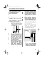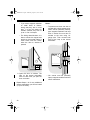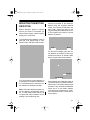
1
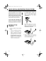
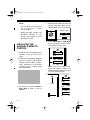
49-2570.fm Page 1 Wednesday, August 18, 1999 3:59 PM
Cat. No. 49-2570
OWNER’S MANUAL
CENTRAL 5000
Monitored Wireless Security Alarm System
Please read before using this equipment.
PANIC
AWAY - ARM - HOME
ZONES
9
10
11
12
13
14
15
16
1
2
3
4
5
6
7
8
ZONES 9-16
BYPASS
ON - LIGHTS - OFF
plug'n power
COMPATIBLE
ARM
MONITOR
AC POWER
BATTERY LOW
MOTION DETECTOR
CENTRAL 5000
MONITORED WIRELESS SECURITY ALARM SYSTEM
PANIC
WIRELESS
SECURITY
SYSTEM
ARM
HOME
•
AUTOMATIC
MESSAGE
DIALLER
ARM
AWAY
DISARM
BATTERY
plug'n power
COMPATIBLE
SECURITY
ON
LIGHT OFF
ARM
PANIC
DISARM
ON
OFF
ON
LIGHTS
OFF
A •
O •
C
•
DIM
E
•
K
BRIGHT
•
M
•
I •
G
•
ENTRY
DELAY
INSTANT
49-2570.fm Page 2 Wednesday, August 18, 1999 3:59 PM
FEATURES
You can install the Radio Shack Central 5000 Monitored Wireless Security
Alarm System anywhere in your home
using existing wiring. The system uses
radio frequencies, so it does not need
more wiring. It includes a handheld remote, a keychain remote, two door/
window sensor transmitters, a motion
detector, and a lamp module so you
can immediately use the system. The
console monitors up to 16 sensor
transmitters (with additional remote
sensor transmitters) and sounds its
built-in alarm and calls ORCA Monitoring Services when a violation occurs.
Here are the system’s features.
Two Door/Window Sensor Transmitters — trigger the console’s built-in
alarm when a secured door or window
opens (additional sensor transmitters,
Cat. No. 49-2585).
Handheld Remote — lets you control
the system plus lights and appliances
connected to Plug ´n Power modules
(additional handheld remotes, Cat. No.
49-2591T).
Keychain Remote — lets you arm/disarm the system and control lights and
appliances (additional keychain remotes, Cat. No. 49-2591).
Lamp Module — lets you turn on/off a
lamp using a remote control. The lamp
also flashes during an alarm (additional lamp modules, Cat. No. 61-2682).
Motion Detector — protects an area
an intruder might enter (additional motion detectors, Cat. No. 49-2589).
Plug ´n Power Compatible Design —
lets you add a total of 16 door/window
sensor transmitters, lamp modules,
motion detectors, and other accessories to customize your system.
Supervised Operation — keeps track
of each door/window sensor transmitter’s status and alerts you if there is a
problem (such as an intrusion or a low
battery).
ORCA-Monitored Security —means
you get 24-hour monitoring to alert the
police, neighbors, or you at work if the
system detects an unauthorized entry.
Auto Timer—gives your home a livedin look when you are away by turning
on one module and randomly turning
on and off up to three other modules
from dusk until about 11:30 PM (requires additional modules).
Important: In some areas, you must
get a permit for monitored alarm service. We recommend that you contact
your local law enforcement agency
and inquire about local alarm permits.
Radio Shack and ORCA, the security monitoring company, are independent of one another.
No warranty or guarantee of performance of the ORCA Monitoring Service Agreement
is provided by Radio Shack.
© 1995 Tandy Corporation. All Rights Reserved.
Radio Shack is a registered trademark used by Tandy Corporation.
ORCA is a registered trademark of ORCA Technology
2
49-2570.fm Page 3 Wednesday, August 18, 1999 3:59 PM
Notes:
• In addition to the parts provided,
you need one 9V alkaline battery
(such as Radio Shack Cat. No.
23-553) to operate the console;
six AAA alkaline batteries (such
as Cat. No. 23-558)—two to operate the keychain remote control
and four to operate the handheld
remote control; and eight AA alkaline batteries (such as Cat. No.
23-552) —two in each door/window sensor transmitter and four to
operate the motion detector.
• The suitability of this system to
perform as a burglar alarm or
emergency service device has not
been evaluated by Underwriters’
Laboratories, Inc.
Warning: To prevent fire or shock hazard, do not expose this product to rain
or moisture.
CAUTION
RISK OF ELECTRIC SHOCK.
DO NOT OPEN.
!
CAUTION: TO REDUCE THE RISK OF
ELECTRIC SHOCK, DO NOT REMOVE
COVER OR BACK. NO USER-SERVICEABLE PARTS INSIDE. REFER SERVICING TO QUALIFIED PERSONNEL.
This symbol is intended to alert you to
the presence of uninsulated dangerous
voltage within the product’s enclosure
that might be of sufficient magnitude to
constitute a risk of electric shock. Do
not open the product’s case.
!
This symbol is intended to inform you
that important operating and maintenance instructions are included in the
literature accompanying this product.
READ THIS BEFORE
INSTALLATION
Your console’s telephone dialer is designed to conform to federal regulations, and you can connect it to most
telephone lines. However, each telephone or telephone device that you
connect to the telephone line draws
power from the telephone line. We refer to this power draw as the device's
ringer equivalence number, or REN.
The REN is shown on the bottom of the
console.
If you use more than one telephone or
other device on the line, add up all the
RENs. If the total is more than five,
your telephones might not ring. In rural
areas, a total REN of three might impair ringer operation. If ringer operation is impaired, remove a device from
the line.
Note: You must not connect your console to:
• Coin-operated systems
• Party-line systems
• Most electronic key telephone
systems
Your console’s telephone dialer complies with Part 68 of FCC Rules. You
must, upon request, provide the FCC
registration number and the REN to
your telephone company. Both numbers are shown on the bottom of the
console.
3
49-2570.fm Page 4 Wednesday, August 18, 1999 3:59 PM
CONTENTS
Glossary . . . . . . . . . . . . . . . . . . . . . . . . . . . . . . . . . . . . . . . . . . . . . . . . . . . . . . . . 6
How the System Works . . . . . . . . . . . . . . . . . . . . . . . . . . . . . . . . . . . . . . . . . . . . 7
Setting Up Monitored Service . . . . . . . . . . . . . . . . . . . . . . . . . . . . . . . . . . . . . 7
Planning Your Security System . . . . . . . . . . . . . . . . . . . . . . . . . . . . . . . . . . . . 10
Assigning Security Zones . . . . . . . . . . . . . . . . . . . . . . . . . . . . . . . . . . . . . . . 11
Reassigning Security Zones . . . . . . . . . . . . . . . . . . . . . . . . . . . . . . . . . . . . . 11
Quick Installing/Testing Your System . . . . . . . . . . . . . . . . . . . . . . . . . . . . . . .
Setting Up the Console . . . . . . . . . . . . . . . . . . . . . . . . . . . . . . . . . . . . . . . . .
Installing the Keychain Remote Control . . . . . . . . . . . . . . . . . . . . . . . . . . . .
Installing the Handheld Remote Control . . . . . . . . . . . . . . . . . . . . . . . . . . . .
Initializing the Door/Window Sensor Transmitters . . . . . . . . . . . . . . . . . . . . .
Initializing the Motion Detector . . . . . . . . . . . . . . . . . . . . . . . . . . . . . . . . . . .
Installing the Lamp Module . . . . . . . . . . . . . . . . . . . . . . . . . . . . . . . . . . . . . .
Testing the System . . . . . . . . . . . . . . . . . . . . . . . . . . . . . . . . . . . . . . . . . . . .
12
12
13
14
15
16
17
18
Mounting Accessories . . . . . . . . . . . . . . . . . . . . . . . . . . . . . . . . . . . . . . . . . . . .
Mounting the Door/Window Sensor Transmitters . . . . . . . . . . . . . . . . . . . . .
Mounting the Motion Detector . . . . . . . . . . . . . . . . . . . . . . . . . . . . . . . . . . . .
Making a Pet Zone . . . . . . . . . . . . . . . . . . . . . . . . . . . . . . . . . . . . . . . . . . . .
Testing the Motion Detector . . . . . . . . . . . . . . . . . . . . . . . . . . . . . . . . . . . . . .
19
19
21
22
22
Operation . . . . . . . . . . . . . . . . . . . . . . . . . . . . . . . . . . . . . . . . . . . . . . . . . . . . . .
Arming/Disarming the System . . . . . . . . . . . . . . . . . . . . . . . . . . . . . . . . . . . .
Arm Away/Arm Home . . . . . . . . . . . . . . . . . . . . . . . . . . . . . . . . . . . . . . .
Instant/Delay Mode . . . . . . . . . . . . . . . . . . . . . . . . . . . . . . . . . . . . . . . . .
Trouble Alarm . . . . . . . . . . . . . . . . . . . . . . . . . . . . . . . . . . . . . . . . . . . . .
Using the Panic Alarm . . . . . . . . . . . . . . . . . . . . . . . . . . . . . . . . . . . . . . . . . .
Zone Indicators . . . . . . . . . . . . . . . . . . . . . . . . . . . . . . . . . . . . . . . . . . . . . . .
Viewing the Status of Zones 9-16 . . . . . . . . . . . . . . . . . . . . . . . . . . . . . .
Other Console Indicators . . . . . . . . . . . . . . . . . . . . . . . . . . . . . . . . . . . .
During an Alarm . . . . . . . . . . . . . . . . . . . . . . . . . . . . . . . . . . . . . . . . . . . . . . .
After an Alarm . . . . . . . . . . . . . . . . . . . . . . . . . . . . . . . . . . . . . . . . . . . . . . . .
Controlling Plug ´n Power Modules . . . . . . . . . . . . . . . . . . . . . . . . . . . . . . . .
Turning Modules On/Off . . . . . . . . . . . . . . . . . . . . . . . . . . . . . . . . . . . . .
Using SECURITY LIGHT . . . . . . . . . . . . . . . . . . . . . . . . . . . . . . . . . . . .
Using BRIGHT/DIM . . . . . . . . . . . . . . . . . . . . . . . . . . . . . . . . . . . . . . . . .
Resetting the Console . . . . . . . . . . . . . . . . . . . . . . . . . . . . . . . . . . . . . . . . . .
23
23
23
23
24
25
25
25
25
26
26
26
26
27
27
27
Troubleshooting . . . . . . . . . . . . . . . . . . . . . . . . . . . . . . . . . . . . . . . . . . . . . . . . . 28
4
49-2570.fm Page 5 Wednesday, August 18, 1999 3:59 PM
Care and Maintenance . . . . . . . . . . . . . . . . . . . . . . . . . . . . . . . . . . . . . . . . . . .
Replacing the Console’s Battery . . . . . . . . . . . . . . . . . . . . . . . . . . . . . . . . . .
Replacing the Remotes’ Batteries . . . . . . . . . . . . . . . . . . . . . . . . . . . . . . . . .
Replacing the Door/Window Sensor Transmitters’ Batteries . . . . . . . . . . . .
Intercom Systems . . . . . . . . . . . . . . . . . . . . . . . . . . . . . . . . . . . . . . . . . . . . .
FCC Cautions . . . . . . . . . . . . . . . . . . . . . . . . . . . . . . . . . . . . . . . . . . . . . . . .
Lightning . . . . . . . . . . . . . . . . . . . . . . . . . . . . . . . . . . . . . . . . . . . . . . . . . . . .
Telephone Line Connection . . . . . . . . . . . . . . . . . . . . . . . . . . . . . . . . . . . . .
32
33
33
34
34
35
35
35
5
49-2570.fm Page 6 Wednesday, August 18, 1999 3:59 PM
GLOSSARY
Here are a few terms that will be helpful to know as you read this manual.
Arm and Disarm — Terms for on and
off. When you arm the system, you
turn on protection. Disarming the system turns off protection.
Away Mode — Your system’s armed
mode when all sensor transmitters (including motion detectors) are armed.
Console — The system’s main control
panel.
Delay Mode —A way of arming the
system so it delays sounding an alert if
a door/window sensor transmitter set
to DELAY reports an intrusion.
Door/Window Sensor Transmitter
— Triggers the alarm when a secured
door or window is opened.
Entry/Exit Delay — A setting on the
handheld remote control that allows
you time while entering and exiting
your house before the system arms or
the alarm trips.
Home Mode — The system’s armed
mode when only doors and windows
are armed (not motion detectors). This
prevents you from accidentally tripping
the motion detector(s) as you move
around the house.
6
Instant Mode — A way of arming the
system so the alarm immediately trips
if a door/window sensor transmitter set
to INSTANT or the motion detector reports an intrusion.
Note: The keychain remote control
only arms the system in the instant
mode.
Motion Detector — Senses motion by
detecting a change in temperature
when someone walks across its path.
Remote Control — A device that lets
you arm and disarm the system away
from the console.
Violation — An alarm condition, such
as that caused by an opened door or
window, detected by a sensor transmitter.
Zone — The area protected by a door/
window sensor transmitter, a motion
detector, or other sensing/transmitting
device.
49-2570.fm Page 7 Wednesday, August 18, 1999 3:59 PM
HOW THE SYSTEM WORKS
After you set up your account with
ORCA Monitoring Services, your system calls and reports alarms to ORCA
Monitoring Services’ trained staff of security professionals. See “During an
Alarm” on Page 26.
The system also automatically calls
ORCA Monitoring Services about once
per month to perform a routine checkin. This call is made between Midnight
and 6 AM to avoid possible interference with other phone calls. If you lift
the handset and hear strange tones,
hang up and wait a few minutes for the
call to end. If ORCA Monitoring Services does not receive a check-in within
this time, they call you to let you know
of a possible problem with the system.
ORCA Monitoring Services can also
have the system blink the MONITOR
indicator and sound a chirp. If you see
this, call 1-800-FOR-ORCA to determine the problem.
SETTING UP
MONITORED SERVICE
Important: Your system is not fully operational until ORCA Monitoring Services programs the system.
To set up service, you need to:
• Fill out the enclosed monitoring
agreement and mail or fax it to
ORCA Monitoring Services.
• Install the system.
• Call ORCA Monitoring Services
by lifting your phone’s handset
and pressing MONITOR on the
console or by dialing 1-800-FORORCA (1-800-367-6722) from a
telephone on the same line as
your system.
During the call, ORCA Monitoring
Services instructs you to press
MONITOR on the system and then
hang up the phone. They then
program option settings (listed on
Pages 8–9) into the system. The
preferred settings work best for
most situations. However, you can
ask ORCA Monitoring Services to
change these settings to make the
system work best for you. (If you
do not ask for changes, the preferred settings are used.)
Note: The system beeps when
programming is complete. To
avoid interrupting system programming, do not lift your telephone’s handset until you hear the
beep.
After ORCA Monitoring Services programs your system, you can begin using it. However, they do not notify
emergency services of an alert until
they have received and responded to
your monitoring agreement. Allow 24
hours for faxed requests and 5 days for
mailed requests.
Note: Call 1-800-FOR-ORCA at least
5 days before you move to another address.
7
49-2570.fm Page 8 Wednesday, August 18, 1999 3:59 PM
Place a check mark next to any settings you want to discuss with ORCA, and refer
to these settings when you call them to set up service.
o
o
House Code
o
Preferred setting: House Code A
Preferred setting: 2, 3, and 4
Can be any House Code (A-P).
Your system can control all modules set to the same house code.
You can select any three Unit
Codes. Modules set to the same
House Code and the three Unit
Codes you select turn on and off
at random times after dusk when
you arm the system in the away
mode. This gives your home a
lived-in appearance.
Flashing Alert Unit Code
Preferred setting: Unit Code 16
Can be any Unit Code (1-16). A
light connected to a module set to
the same House and Unit Codes
you select flashes when the alarm
is tripped, and can be controlled
by the SECURITY LIGHT buttons
on the handheld remote. This light
also turns on at dusk and turns off
around 11:30 PM when the system is armed in the away mode.
o
Silent Alarm
Preferred setting: Audible alarm
Can be set to only call ORCA
Monitoring Services and not
sound the siren at all. If you select
silent alarm, you will hear no indication that the system has been
tripped.
8
Lived-In Look Unit Codes
o
Entry and Exit Delays
Preferred setting: 60-second exit
delay; 30-second entry delay
Each can be set from 0 to 1000
seconds.
o
Dial Delay
Preferred setting: 40 Seconds
Can be set from 0 to 1000 seconds. This sets how long the console waits after it has been tripped
before it calls ORCA Monitoring
Services.
49-2570.fm Page 9 Wednesday, August 18, 1999 3:59 PM
o
Touch-Tone Dialing
Lights Off Time
Touch-tone
Preferred setting: Turn random
and security lights off at 11:30 PM
Can be set to use rotary dialing if
you do not subscribe to touchtone service from your local telephone company.
Can be set to any time. The security light turns on and lived-in
lights randomly turn on and off
around dusk, then turn off at the
time you select here.
Preferred
dialing
o
o
setting:
Alarm Flash Option
Preferred setting: Flash only the
module set to the House and
Flashing Alert Unit Code you
select
You can have the system flash all
light modules set to the same
House Code or flash no modules
at all.
o
Panic Alarm Dial
Preferred setting: Always call
ORCA Monitoring Services when
the panic alarm is tripped
Can be set to only call ORCA
Monitoring Services if the system
is armed when the panic alarm is
tripped.
9
49-2570.fm Page 10 Wednesday, August 18, 1999 3:59 PM
PLANNING YOUR SECURITY SYSTEM
Before you set up your system, draw a
security plan of your home. This is especially important if you install sensor
transmitters to protect several different
zones.
If you live in an upstairs apartment, the
front door might be the best place to
mount a door/window sensor transmitter. If you live in a house or downstairs
apartment, you might want to cover a
back door or window.
Your security system has three goals:
• To prevent loss by discouraging
potential intruders.
• To scare intruders away before
they can take your property or
break into your home.
• To alert ORCA that someone is
breaking into your home.
To help accomplish these goals, you
should:
• Post decals on doors and windows stating that your home is
protected by a security system.
Monitored Alarm decals are
included with your system. Additional decals (Cat. No. 49-507) are
available at your local Radio
Shack store.
• Choose a location for the console
where it is not easily accessible or
seen by intruders.
In addition, most police departments
offer information that might be helpful.
After making a preliminary plan, contact your local police department to
see if they offer guidelines or other services for planning a home security system.
Floorplan Goes Here
10
49-2570.fm Page 11 Wednesday, August 18, 1999 3:59 PM
ASSIGNING SECURITY
ZONES
REASSIGNING
SECURITY ZONES
A security zone is an area of protection
covered by a single door/window sensor transmitter, motion detector, or other sensing/transmitting device. Your
security console monitors up to 16
zones and alerts you if there is a violation (see “Zone Indicators”).
If you want to remove one accessory,
reassign an accessory to a zone currently in use, or add an accessory
when all zones are assigned, you must
completely reinitialize the system.
When you initialize your security system’s sensor transmitters, the console
assigns a zone number to the sensor
transmitter (see “Initializing the Door/
Window Sensor Transmitters”). The kit
includes numbered stickers you attach
to each sensor transmitter to show its
zone number.
To reinitialize the system, set INSTALL/
RUN 1/RUN 2 to INSTALL. Then press
PANIC, ARM HOME, and ARM AWAY on
the console at the same time. Reinitialize all remote controls, door/window
sensor transmitters, and motion detectors, assigning each accessory to the
desired zone.
For your reference, make a record of
which area of your home a zone covers. For example, using the floorplan
you drew, you could mark the front
door as “Zone 1.”
11
49-2570.fm Page 12 Wednesday, August 18, 1999 3:59 PM
QUICK INSTALLING/TESTING YOUR SYSTEM
This section describes how to initialize
system accessories so the console
recognizes them and how to test the
system to make sure it works properly.
Perform all the procedures in this section, then follow the instructions in “Locating and Mounting Accessories.”
2. For backup power in case of an
AC power failure, connect and
place a 9-volt alkaline battery
(Cat. No. 23-553) in the battery
compartment.
You can add other separately purchased accessories to the system by
following the appropriate initialization
and testing procedures in this section.
SETTING UP THE
CONSOLE
3. Plug the console into any standard AC outlet that is not controlled by an on/off switch, then
fully extend the antenna.
1. Choose a location for the console
that is:
• Close to a modular phone jack.
• Central to doors/windows you
want to protect so all sensor
transmitters are within 100 feet.
• Positioned where you can easily check the zone indicators for
problems, but not where an
intruder could easily see it.
12
4. Plug the telephone cord into the
console and plug the other end
into a modular phone jack.
49-2570.fm Page 13 Wednesday, August 18, 1999 3:59 PM
Notes:
• If you do not have an unused jack,
use the supplied duplex adapter.
For a baseboard jack, plug the
adapter into the jack; for a wall
jack, plug the adapter into the
console.
To
TELEPHONE
Telephone
CORD
INSTALLING THE
KEYCHAIN REMOTE
CONTROL
1. Remove the keychain remote control’s back cover. Install two AAA
alkaline batteries (Cat. No. No.
23-555) in the battery compartment, according to the polarity
symbols (+ and –) marked inside.
Then replace the cover.
2. Set the console’s INSTALL/RUN 1/
RUN 2 switch to INSTALL .
• If you do not have a modular
phone jack, you can either update
the wiring yourself or have the
phone company do it for you.
Radio Shack stores sell the jacks
and adapters you need. The
phone company charges to install
the jacks. The USOC number of
the jack to be installed is RJ11C
for a baseboard jack or RJ11W for
a wall jack.
3. Stand near the console and press
ARM on the remote control. The
console chimes and logs in the
remote control.
BATTERY
ARM
PANIC
DISARM
ON
LIGHTS
OFF
4. Leave the console’s switch set to
INSTALL to install other accessories.
13
49-2570.fm Page 14 Wednesday, August 18, 1999 3:59 PM
Notes:
• You can add any combination of
up to eight Plug ´n Power
remote controls.
• When you press a button, the
BATTERY indicator on the
remote control lights to show
the battery is good.
INSTALLING THE
HANDHELD REMOTE
CONTROL
4. Set the house code on the remote
control to the same letter as you
selected when you set up service.
A •
O •
C
•
M
DIM
E
•
K
BRIGHT
•
•
I •
G
•
ENTRY
DELAY
INSTANT
5. Press ARM HOME or ARM AWAY
on the handheld remote control.
The console sounds a tone.
PANIC
1. Press the tab on the battery compartment cover and lift off the
cover.
2. Install four AAA alkaline batteries
(Cat. No. 23-555) in the handheld
remote control’s battery compartment, according to the polarity
symbols (+ and –) marked inside
the compartment.
ARM
HOME
ARM
AWAY
ON
DISARM
SECURITY
LIGHT OFF
Note: If you do not hear a tone,
press the button beneath the
remote control’s label with a pencil. Then repeat this step.
WIRELESS
SECURITY
SYSTEM
•
PANIC
ARM
HOME
Press
3. Be sure the console’s INSTALL/
RUN 1/RUN 2 switch is set to
INSTALL .
14
AUTOMATIC
MESSAGE
DIALLER
ARM
AWAY
plug'n power
DISARM
ON
SECURITY
LIGHT OF
ON
OF
COMPATIBLE
49-2570.fm Page 15 Wednesday, August 18, 1999 3:59 PM
6. Leave the console’s switch set to
INSTALL to install other accessories.
zone indicator on the console
lights to show which zone the sensor transmitter is assigned to.
7. Replace the compartment cover.
Note: You can install eight keychain
(Cat. No. 49-2591) or handheld remote
controls (Cat. No. 49-2551T).
–
+
DELAY
MAX
INITIALIZING THE DOOR/
WINDOW SENSOR
TRANSMITTERS
1. Open a door/window sensor
transmitter’s battery compartment.
Install two AA alkaline batteries
(Radio Shack Cat. No. 23-557).
DELAY
MAX
MIN
TEST
2. Be sure the console’s INSTALL/
RUN 1/RUN 2 switch is set to
INSTALL .
3. Stand near the console and press
TEST, located to the right of the
sensor transmitter’s battery compartment. The console chimes
and logs in the door/window sensor transmitter. The first available
+
MIN
–
TEST
Note: If you do not hear a chime,
remove the batteries from the sensor transmitter and then hold
down the TEST button for 3 seconds. Reinstall the batteries and
press TEST again. When the indicator flashes twice, you can initialize the sensor transmitter as
described in Step 3.
4. Set DELAY, located inside the
door/window sensor transmitter’s
battery compartment, to MIN to
protect a window or to MAX to protect a door. Then replace the battery compartment’s cover.
–
+
DELAY
MAX
+
MIN
–
TEST
15
49-2570.fm Page 16 Wednesday, August 18, 1999 3:59 PM
5. Place one of the supplied numbered stickers on the sensor
transmitter to show its zone number.
6. Leave the console’s switch set to
INSTALL to install other accessories.
Repeat these steps for additional door/
window sensor transmitters.
3. Be sure the console’s INSTALL/
RUN 1/RUN 2 switch is set to
INSTALL.
4. Press TEST on the back of the
motion detector. The console
chimes, and the first available
zone indicator lights to show the
console has logged in the motion
detector.
INITIALIZING THE
MOTION DETECTOR
1. Press the four dots on the battery
compartment cover and slide the
cover down to remove it.
TEST
CODE
If you do not hear a chime, press
CODE with a pencil, then press
TEST again.
5. Looking at the back of the motion
detector, set the switch on the left
side to 1 (see “Mounting the
Motion Detector”).
1
2
MOTION DETECTOR
2. Install four 1.5V AA alkaline batteries (Cat. No. 23-552) inside the
motion detector’s battery compartment according to the polarity
symbols (+ and –) marked inside.
16
6. Place one of the supplied numbered stickers on the motion
detector to show its zone number.
7. Leave the console’s switch set to
INSTALL to install other accessories.
8. Replace the motion detector’s battery compartment cover.
49-2570.fm Page 17 Wednesday, August 18, 1999 3:59 PM
INSTALLING THE LAMP
MODULE
When the alarm trips, lamps connected to lamp modules flash on and off for
the duration of the alarm. After 4 minutes (or when you disarm the alarm),
the lamps stop flashing and remain on.
If you arm the system with an exit delay, lamp modules set to the same
House and Unit Code as the console
turn on during the exit countdown.
You can also control lamp modules set
to this code using SECURITY LIGHT on
the handheld remote.
Follow these steps to install a lamp
module.
1. Plug a lamp into the supplied lamp
module and plug the module into
an AC outlet that is on the same
electrical circuit as the console.
Replace with the actual illustration
Note: Do not plug an appliance or
fluorescent lamp into the supplied
module.
2. Be sure the lamp’s switch is on.
3. Set the module’s House and Unit
Code dials to the same codes you
selected when you set up service.
17
49-2570.fm Page 18 Wednesday, August 18, 1999 3:59 PM
TESTING THE SYSTEM
After you complete the quick installation procedures, follow these steps to
test the system.
Note: To avoid alarming neighbors, tell
them you are testing the system.
1. Set INSTALL/RUN 1/RUN 2 on the
console to RUN 2.
2. Place each door/window sensor
transmitter’s magnet next to its
magnetic switch.
WIRELESS SENSOR TRANSMITTER
3. Place the motion detector on a
counter top within 100 feet of the
console.
4. Move a door/window sensor
transmitter’s magnet away from
the magnetic switch.
When the system is not armed,
the console chimes every time
someone opens a door or window
with the system in the RUN 2
mode. The system does not chime
in the RUN 1 mode.
Replace the magnet next to the
magnetic switch.
18
5. Press ARM on a remote control,
and then move the magnet away
from the magnetic switch again.
The alarm sounds and the lamp
connected to the lamp module
flashes on and off. Press DISARM
to turn off the alarm, and LIGHTS
OFF to turn off the lamp. Replace
the magnet next to the magnetic
switch.
6. Press ARM on the remote control,
then walk across the path of the
motion detector’s lens. The alarm
sounds and the lamp connected
to the lamp module flashes on and
off. Press DISARM to turn off the
alarm. The console chimes twice.
Press LIGHTS OFF to turn off the
lamp.
49-2570.fm Page 19 Wednesday, August 18, 1999 3:59 PM
MOUNTING ACCESSORIES
MOUNTING THE DOOR/
WINDOW SENSOR
TRANSMITTERS
You can install any combination of
door/window sensor transmitters (Cat.
No. 49-2585) and motion detectors
(Cat. No. 49-2589), in up to 16 zones.
Follow these steps to mount each
door/window sensor transmitter.
1. Set the DELAY switch on the door/
window sensor transmitter to MIN
to protect a window or to MAX to
protect a –door.+
3. The supplied sensor transmitter
and magnet switch are connected.
If the wire is too long, shorten it by
cutting it to the length required,
stripping the ends, and reconnecting it to the magnetic switch.
4. Remove the sensor transmitter’s
batteries and attach it to the wall
using the supplied screws or double-sided tape (such as Radio
Shack Cat. No. 64-2361). Then
replace the batteries (if you
removed them) and close the battery compartment door.
5. Align the arrows on the switch and
magnet, then install the switch
and magnet using the supplied
screws or double-sided tape.
DELAY
MAX
+
MIN
–
TEST
Note: The MAX setting lets you
arm a sensor transmitter with a
60-second exit delay and a 30second entry delay (see “Instant/
Delay Mode”). When set to MIN,
the sensor transmitter immediately triggers the alarm if it is triggered after the exit delay.
2. Select a location for the door/window sensor transmitter. We recommend that you purchase
enough sensor transmitters to
protect the front and back door
and any windows that are hidden
from view or easily accessible
(including basement windows).
WIRELESS SENSOR TRANSMITTER
Notes:
• Do not mount the magnet
directly onto a metal surface. If
necessary, use a wood or plastic spacer.
19
49-2570.fm Page 20 Wednesday, August 18, 1999 3:59 PM
• If you mount magnetic switches
on metal doors or frames,
ensure that they are no more
than 3/16 of an inch apart. On
wooden surfaces, they can be
up to 3/8 of an inch apart.
• For sliding doors/windows, it is
best to mount the magnet and
switch so the magnet makes a
clean break from the switch
when the door or window is
opened.
Notes:
• To protect more than one door or
window with a single sensor transmitter, use NC (Normally Closed)type magnetic switches and loop
them in series from one door or
window to the next using 18gauge wire. Then connect both
ends of the loop to the sensor
transmitter.
WIRELESS SENSOR TRANSMITTER
WIRELESS SENSOR TRANSMITTER
6. Open the door or window. The
light on the sensor transmitter
turns on each time you open the
door or window.
Repeat Steps 1–6 for any additional
sensor transmitters you want to install
(in up to 16 zones).
20
• You cannot use NO (Normally
Open) magnetic switches with this
sensor transmitter.
49-2570.fm Page 21 Wednesday, August 18, 1999 3:59 PM
MOUNTING THE MOTION
DETECTOR
Motion detectors protect a specific
area of your home. For example, you
might want to protect a stereo system,
jewelry box, or wall safe.
Secure the bracket to the detector’s
bottom using the supplied machine
screw. Then secure the bracket to the
wall. Finally, loosen the screw on the
hinge and adjust the detector to be level, then tighten the screw to hold the
detector in position.
The supplied motion detector sees 40
feet with a 90 degree field of view.
Place it within 100 feet of the console.
Wrong
Right
For the best coverage, place the motion detector at a height of 6 feet, then
position the lens so an intruder walks
across its path rather than toward it.
More Sensitive
Less Sensitive
You can place the motion detector on
a countertop or use the included bracket. The bracket lets you swivel the motion detector for the best coverage.
Note: The motion detector senses motion by detecting temperature changes. To help prevent false alarms, do
not place the motion detector near a
heating or air conditioning vent.
Set the switch on the detector’s back to
1 (most sensitive) or 2 (least sensitive).
When set to 1, the motion detector trips
the alarm if any movement is detected.
When set to 2, the motion detector
must detect two movements or continuous movement within a short time to
trip the alarm.
21
49-2570.fm Page 22 Wednesday, August 18, 1999 3:59 PM
MAKING A PET ZONE
3. Release TEST and wait about 20
seconds.
If you have a pet, you can help reduce
the chance the pet will cause a false
alarm by blocking the motion detector’s lower zones with the supplied
tape.
4. Walk past the motion detector.
The indicator lights as you move
and turns off if you keep still or
walk out of the detector’s range.
To use the tape, place it over the lower
zones of the detector’s lens.
Lower
Zones
TESTING THE MOTION
DETECTOR
The motion detector includes a special
test mode. Follow these steps to test
the motion detector.
1. Set the sensitivity switch to 1.
2. Hold down TEST on the back of
the motion detector until the indicator flashes twice.
22
Notes:
• If the range is low (less than 30
feet), check that the detector is
horizontal and at least 5 feet from
the ground.
• The motion detector automatically switches to normal operation
after 2 minutes in the test mode.
To switch it back sooner, hold
TEST down until the indicator
flashes twice (about 3 seconds).
To test the alarm with the motion detector, arm the console and wait about
45 seconds. Then walk in front of the
motion detector and check that the
alarm is triggered. After the motion detector triggers the alarm, it automatically locks out for 45 seconds to save
battery power.
49-2570.fm Page 23 Wednesday, August 18, 1999 3:59 PM
OPERATION
ARMING/DISARMING
THE SYSTEM
You can arm the system three ways:
• Set INSTALL/RUN 1/RUN 2 on the
console to RUN 1 or RUN 2 and
press ARM on the console.
• Set INSTALL/RUN 1/RUN 2 on the
console to RUN 1 or RUN 2 and
press ARM AWAY or ARM HOME
on the handheld remote control.
See “Arm Away/Arm Home” and
“Instant/Delay Mode.”
• Set INSTALL/RUN 1/RUN 2 on the
console to RUN 1 or RUN 2 and
press ARM on the keychain
remote control.
The console beeps once when you
arm it. When the system is armed, the
RUN 1 and RUN 2 setting have the
same effect: opening a door or window
with a sensor transmitter attached or
tripping a motion detector sets off the
alarm.
Arm Away/Arm
Home
WIRELESS
SECURITY
SYSTEM
•
AUTOMATIC
MESSAGE
DIALLER
ARM
HOME
ARM
DISARM
AWAY
All sensor transmitters arm when you
press ARM AWAY. Also, a module set
to the same House and Flashing Alert
Unit Code you selected when you set
up service with ORCA Monitoring Services turns on at dusk and off around
11:30 PM and modules set to the same
House Code and Lived-In Look Unit
Codes you selected turn on and off at
random intervals.
If you press ARM HOME, only doors
and windows arm. This lets you arm
the system at night without tripping the
motion detector.
Instant/Delay Mode
The only difference between RUN 1
and RUN 2 is that when the system is
set to RUN 2 and not armed, the console sounds a pleasant chime when
you open a door or window. When it is
set to RUN 1, there are no chimes.
With ENTRY on the handheld remote
set to INSTANT (and DELAY on the sensor transmitter(s) set to MIN), the system instantly arms and the alarm
immediately trips if any sensor transmitter reports an intrusion.
To disarm the system, press DISARM
on any remote control. The console
beeps twice.
With ENTRY on the handheld remote
set to DELAY, you have a 60-second
exit delay and a 30-second entry delay
before the system arms or trips. A
warning chime sounds during the delay period.
23
49-2570.fm Page 24 Wednesday, August 18, 1999 3:59 PM
Notes:
• The supplied motion detector
(Cat. No. 49-2589) only operates
in the AWAY and MIN modes.
If you want to use the exit/entry
delay feature, you can use
another motion detector (Cat. No.
61-2614) instead of the one supplied with this system.
• You must set the switch inside the
door/window sensor transmitter’s
battery compartment to MAX in
order for it to arm in the delay
mode. When set to MIN, the sensor transmitter immediately arms,
regardless of whether the handheld remote control is set to
DELAY or INSTANT.
• The ARM button on the console
automatically arms the system in
the DELAY mode.
Trouble Alarm
If you hear a repetitive trouble alarm
when you try to arm the system, this indicates that there is a problem.
The system does not arm until you:
• Correct the Problem — Press
DISARM to stop the trouble alarm.
Check the zone reporting the
problem to see if a door or window
is open or a sensor transmitter’s
battery is dead. Then arm the system again.
• Ignore the Problem — Press
BYPASS on the console while the
trouble alarm is sounding. The
problem zone’s indicators flash
rapidly. Press ARM HOME/ARM
AWAY to arm the system. The
problem zone(s) are not protected, but all other zones arm.
PANIC
• The keychain remote control only
arms the system in the INSTANT
mode.
• Other
separately
purchased
remote controls might arm the
system only in either the DELAY or
INSTANT mode. See the remote
control’s owner’s manual.
• The system ignores sensor transmitters operating in the MIN mode
(such as the supplied motion
detector) during the entry delay.
24
AWAY - ARM - HOME
BYPASS
ZONES 9-16
ON - LIGHTS - OFF
plug'n power
COMPATIBLE
MONITOR
AC POWER
BATTERY LOW
Note: If you bypass an open window or
door, arm the system, and later close
the window or door, that zone arms.
49-2570.fm Page 25 Wednesday, August 18, 1999 3:59 PM
USING THE PANIC
ALARM
Pressing PANIC on the handheld remote control, or ARM and DISARM at
the same time on the keychain remote
control, causes the console’s alarm to
sound, even if the system is not armed.
ZONE INDICATORS
All sensor transmitters and motion detectors report to the console about every 90 minutes. If the console does not
receive a signal from a sensor transmitter within 4 hours, it reports a problem with that sensor transmitter by
slowly flashing its zone indicator.
ZONES
1
2
3
4
5
6
7
8
9
10
11
12
13
14
15
16
The console’s zone status indicators
show four conditions for Zones 1–8:
• Fast Flashing — door/window
sensor transmitter reported a
problem (such as an open window
or low battery) and you pressed
BYPASS on the console (see
“Troubleshooting”).
Viewing the Status of
Zones 9-16
If there is a problem with Zones 9–16,
the console does not flash a zone light,
but you hear the trouble alarm if you try
to arm the system.
Press and hold ZONES 9-16 on the console. The indicators show which zone
(9–16) is reporting the problem. If you
do not want to bypass the problem,
correct it and arm the system again.
Other Console Indicators
• BATTERY LOW (Steady) — battery in console is low or needs
replacement.
• ARMED (Steady) — indicates
system is armed.
• Steady On — door or window is
open.
• Steady Off — door or window is
closed.
• Slow Flashing — door/window
sensor transmitter is reporting a
problem (such as a low battery).
25
49-2570.fm Page 26 Wednesday, August 18, 1999 3:59 PM
DURING AN ALARM
When there is a violation, the console
sounds a siren for 4 minutes, flashes
ARMED, and lights the indicator for the
affected zone. The system calls ORCA
Monitoring Services and advises them
of the alarm, and flashes lights connected to lamp modules.
The ORCA Monitoring Services staff
first tries to contact you at home to verify that it is not a false alarm. By calling
you first, ORCA Monitoring Services
ensures that the police are not contacted if you accidentally set off your
alarm.
In alarm situations, the monitoring center dispatches the police to your address and tries to contact someone
you listed on your emergency call list.
ORCA Monitoring Services tries each
number once in the order that you listed them on your monitoring agreement. If ORCA Monitoring Services
contacts one of the people listed, they
do not disturb the other people on the
list.
dicator and the violated zone’s indicator lights steadily.
Arm then disarm the system to turn off
the ARMED and zone indicators.
Press LIGHTS OFF to turn off the lamp
modules.
If you return home and the ARMED indicator is flashing, call 1-800-FORORCA to determine the cause of the
alarm.
CONTROLLING PLUG ´N
POWER MODULES
Turning Modules On/Off
Use the four ON/OFF buttons on the
handheld remote control to control
lights or appliances connected to Plug
´n Power modules. Set the light/appliance modules to the same House
Code as the console. Set the light/appliance modules’ Unit Codes to 1, 2, 3,
or 4.
ON
OFF
1
AFTER AN ALARM
When you disarm the system after an
alarm (or about 4 minutes after the
alarm trips), the console’s siren turns
off, but the lights connected to lamp
modules remain on to let you know
there was a violation. The ARMED in-
26
2
3
4
A •
O •
C
BRIGHT
•
•
M
E
•
K
G
•
ENTRY
DIM
49-2570.fm Page 27 Wednesday, August 18, 1999 3:59 PM
Using SECURITY LIGHT
Use the SECURITY LIGHT button on the
handheld remote control or the console to turn on/off a light module set to
the same House and Unit Code as you
selected when you set up the system.
AUTOMATIC
MESSAGE
DIALLER
ARM
AWAY
plug'n power
DISARM
ON
SECURITY
LIGHT OFF
ON
OFF
COMPATIBLE
RESETTING THE
CONSOLE
To remove all sensor transmitters from
memory, set the console’s INSTALL/
RUN 1/RUN 2 switch to INSTALL. Then
press PANIC, ARM HOME, and ARM
AWAY at the same time.
Note: This does not clear the settings
that ORCA Monitoring Services programmed into your system during initialization.
Using BRIGHT/DIM
Use the BRIGHT/DIM button on the
handheld remote control to brighten or
dim lights connected to Plug ´n Power
lamp modules.
Turn on the module by pressing the remote control ON button that corresponds to the module’s Unit Code.
Then press and hold BRIGHT or DIM on
the remote control until the light reaches the desired brightness.
A •
O •
C
BRIGHT
•
•
M
E
•
K
•
I •
G
•
DIM
ENTRY
DELAY
INSTANT
Note: You cannot brighten or dim
lamps connected to appliance modules.
27
49-2570.fm Page 28 Wednesday, August 18, 1999 3:59 PM
TROUBLESHOOTING
If you experience problems with your security console or accessories, try correcting
the problem as suggested in this section. If you cannot correct the problem, contact
your local Radio Shack store for assistance.
Problem
The system does not arm.
Solution
• Check that INSTALL/RUN 1/RUN 2 on the console is
in the RUN 1 or RUN 2 position.
• If you are using a remote control to arm the system,
check that the battery indicator on the remote control turns on when you press ARM on the keychain
remote control or ARM HOME/ARM AWAY on the
handheld remote control. Replace the battery and
re-initialize the remote control, if necessary.
A zone indicator flashes slowly.
A sensor transmitter/motion detector has not reported in
within 4 hours. Check the sensor transmitter/motion detector’s battery or bypass the zone.
A zone indicator flashes rapidly.
You pressed BYPASS on the console to arm the system
while a sensor transmitter/motion detector was reporting
a problem. The zone arms when you correct the problem.
You hear a repetitive trouble
alarm when you try to arm the
system, and it does not arm.
Check the zone indicators. If a door or window is open,
its zone indicator is on. If there is a problem with a sensor
transmitter or motion detector, its zone indicator flashes
slowly. You can correct this two ways:
• Press DISARM. Check that each door/window sensor transmitter is working and that you have not left
a door or window open. Then arm the system.
• While the trouble alarm sounds, press and hold
BYPASS on the console to override the problem
zone (its zone indicator then flashes rapidly). Then
arm the system.
The alarm trips when you enter the house before you have
time to disarm it.
• Arm the system in the delay mode. Set the DELAY
switch on the entry door sensor transmitter to MAX.
Set the ENTRY switch on the handheld remote control to DELAY, and then press ARM AWAY on the
handheld remote control.
• Disarm the system before you trip a sensor (such
as the supplied motion detector) set to MIN.
28
49-2570.fm Page 29 Wednesday, August 18, 1999 3:59 PM
Problem
You cannot turn lights on or off
from the LIGHT ON or LIGHT
OFF buttons on the remote.
Solution
• Make sure you set the house and unit code on the
module(s) to the same letter and number as you
selected for the console.
• Be sure the light you are trying to control is plugged
in and has its on/off switch in the on position, and
that its bulb is good.
• Plug the module into another outlet on the same
electrical circuit as the console.
• Check that the battery indicator on the remote control comes on when you press a button. Replace the
battery and re-initialize the remote control, if necessary.
• Make sure INSTALL/RUN 1/RUN 2 is not set to
INSTALL.
You open a door or window
and the alarm does not trip.
• Check to see if the system is armed.
• Be sure INSTALL/RUN 1/RUN 2 on the console is set
to RUN1 or RUN 2.
• Press TEST on the door/window sensor transmitter
and see if the alarm trips. If the alarm does not trip,
see if the sensor transmitter indicator comes on
when you press TEST. If the indicator does not
come on, replace the battery and re-initialize the
sensor transmitter, if necessary.
Appliances turn off during an
alarm.
The system flashes lights by repetitively transmitting the
signal to turn all units on or all units off. Therefore, any
appliances connected to appliance modules which were
on at the time of the alarm, turn off and stay off.
If you do not want this to happen, set the appliance module(s) to a different house code than you selected for the
console.
29
49-2570.fm Page 30 Wednesday, August 18, 1999 3:59 PM
Problem
Solution
You do not hear a chime from
the console when you press
ARM to install a remote.
Check if you can arm the system when INSTALL/RUN 1/
RUN 2 on the console is set to RUN 1 or RUN 2. If you can,
the remote control is already installed and no further action is necessary. If not:
1. Set INSTALL/RUN 1/RUN 2 on the console to
INSTALL.
2. Press CODE (located beneath the label on the
remote control) with a pencil, then press ARM again.
You do not hear a chime from
the console when you press
TEST to install a door/window
sensor transmitter or motion
detector.
With INSTALL/RUN 1/RUN 2 on the console set to RUN 2,
check that the console chimes when you press TEST on
the sensor transmitter or motion detector. If it does, the
sensor transmitter or motion detector is already installed
and no further action is necessary. If not:
1. Set INSTALL/RUN 1/RUN 2 on the console to
INSTALL.
2. Press CODE on the motion detector with a pencil or
remove then reinstall the batteries in the sensor
transmitter. Then press TEST again.
Note: If the sensor transmitter/motion detector is already
installed, it is installed again into the next available zone.
The BATTERY LOW indicator
on the console is on.
Replace the console’s battery.
You lose your remote control.
Purchase a replacement remote control (Cat. No. 492591T or 49-2591), and then completely re-install your
system to prevent someone else from using the lost remote control.
The system arms or disarms
by itself.
A neighbor might have a compatible system. Re-install
the remotes.
The red indicator on the handheld remote control stays on
during installation.
Press the button located beneath the label with a pencil
and then press ARM. If it still stays on, remove the battery, wait a few seconds, then replace the battery. Press
the button and then ARM again.
30
49-2570.fm Page 31 Wednesday, August 18, 1999 3:59 PM
Problem
Solution
The red indicator on the sensor transmitter/motion detector stays on during installation.
Remove then reinstall the sensor transmitter/motion detector’s batteries. Press TEST again.
The ARMED indicator is flashing.
This indicates that there has been an intrusion. Also, if a
zone indicator is on, this indicates which zone was violated. To turn the zone indicator off and stop the armed indicator from flashing, press the ARM or DISARM button on
a remote control. If a zone indicator is not on, the violated
zone is within Zones 9-16. Press ZONES 9-16 on the console to see which zone was tripped.
A motion detector causes false
alarms .
• Motion detectors sense motion by detecting a
change in temperature; therefore, do not place the
motion detector near an air conditioning or heating
vent.
• Do not place it in a direct source of bright light, such
as sunlight.
• It could be detecting a pet’s movements. Set the
switch on the back to 2 so it is less sensitive or
cover its bottom zones.
31
49-2570.fm Page 32 Wednesday, August 18, 1999 3:59 PM
CARE AND MAINTENANCE
Your Radio Shack Wireless Home Security System with Emergency Phone Dialer is
an example of superior design and craftsmanship. The following suggestions will
help you care for your system so you can enjoy it for years.
Keep all system components dry. If anything gets wet, wipe it dry immediately. Liquids can contain minerals that corrode the electronic
circuits.
Handle your console and accessories gently and carefully. Dropping
them can damage circuit boards and cases and can cause them to
work improperly.
Use and store the console and accessories only in normal temperature environments. Extreme temperatures can shorten the life of electronic devices and distort or melt plastic parts.
Keep the console away from dust and dirt which can cause premature wear of parts.
CLEANER
Wipe the console with a damp cloth occasionally to keep it looking
new. Do not use harsh chemicals, cleaning solvents, or strong detergents to clean your console.
Use only fresh batteries of the required size and type. Always remove
old or weak batteries. They can leak chemicals that destroy electronic
circuits.
Modifying or tampering with the system’s internal components can cause a malfunction and might invalidate its warranty and void your FCC authorization to operate it.
If your system is not performing as it should, contact your local Radio Shack store
for assistance. If the console is harming the telephone lines, the telephone company
might ask you to disconnect your console from the telephone line until you have resolved the problem.
32
49-2570.fm Page 33 Wednesday, August 18, 1999 3:59 PM
REPLACING THE
CONSOLE’S BATTERY
The console’s backup battery allows
the system to work during a power outage. A 9-volt alkaline battery provides
at least 12 hours of backup. The BATTERY LOW indicator on the console
lights when you need to replace the
backup battery, but you should replace
the battery at least once a year.
REPLACING THE
REMOTES’ BATTERIES
If the system arms, the console recognized the remote control.
If the system did not arm:
1. Set INSTALL/RUN 1/RUN 2 to
INSTALL.
2. Press ARM on the remote control.
The remote control transmits a
random code to the console. The
console acknowledges this with a
beep and logs in the remote control. If you do not hear a beep,
press CODE with a pencil and then
press ARM.
If the console does not respond to a remote control’s signal, replace the remote control’s batteries, according to
the polarity markings (+ and –) inside
the battery compartment. After you replace the remote control’s batteries,
re-initialize the remote control as described in “Initializing the Keychain Remote Control” or “Initializing the
Handheld Remote Control.”
Note: When you press a button on the
keychain remote, its BATTERY indicator lights to show the battery is good.
After replacing batteries, follow these
steps to confirm that the console still
recognizes the remote control.
1. Set INSTALL/RUN 1/RUN 2 on the
console to RUN 2.
2. Press ARM on the remote control.
33
49-2570.fm Page 34 Wednesday, August 18, 1999 3:59 PM
REPLACING THE DOOR/
WINDOW SENSOR
TRANSMITTERS’
BATTERIES
If any of the console’s zone indicators
flash slowly, the door/window sensor
transmitter or motion detector for that
zone has not reported in during the last
4 hours. This is most likely caused by
a dead battery.
Replace the door/window sensor
transmitter or motion detector’s battery, then follow these steps to confirm
that the console still recognizes it.
1. Set INSTALL/RUN 1/RUN 2 on the
console to RUN 2.
2. Press TEST on the sensor transmitter or motion detector.
If the console chimes, it recognizes the
sensor transmitter or motion detector.
If you do not hear a chime when you
press TEST:
1. Set INSTALL/RUN 1/RUN 2 on the
console to INSTALL.
2. Press TEST. The sensor transmitter transmits a code to the console, and the console chimes to
confirm it accepted the code.
34
When you press TEST, the system
assigns the sensor transmitter to
the first available zone. If a zone’s
indicator is flashing (to indicate
that zone’s sensor transmitter has
not reported in in the last 4 hours),
the zone is considered available.
INTERCOM SYSTEMS
Intercom systems which send voice
signals over existing electrical wiring
might interfere with the ability to control
Plug ´n Power modules from your security system when the intercom is in
use.
If the intercom system has separate
wiring, it does not cause a problem.
49-2570.fm Page 35 Wednesday, August 18, 1999 3:59 PM
FCC CAUTIONS
Your system has been tested and
found to comply with the limits for a remote control security device in accordance with Part 15 of FCC Rules ,
which are designed to provide reasonable protection against interference in
a residential installation. However,
there is no guarantee that interference
will not occur in a particular installation.
If this system interferes with radio or
television reception, which can be determined by unplugging the equipment, try to correct the interference by:
• Reorienting the antenna of the
radio/TV experiencing the interference.
• Moving the system away from the
radio/TV.
• Plugging the system into an outlet
on a different circuit from the
radio/TV experiencing the interference.
If necessary, contact your local Radio
Shack store for additional suggestions.
LIGHTNING
Your system has built-in protection circuits to reduce the risk of damage from
surges in telephone and power line
current. These protection circuits meet
or exceed FCC requirements. However, lightning striking the telephone or
power lines might damage the system.
Lightning damage is not common.
Nevertheless, if you live in an area that
has severe electrical storms, we suggest that you unplug the system and
rely on its battery power during storms
to reduce the possibility of damage.
TELEPHONE LINE
CONNECTION
The telephone portion of your security
console has been tested and found to
comply with applicable UL and FCC
standards.
In the unlikely event that your console
causes problems on the telephone
line, the telephone company can disconnect your service. The telephone
company attempts to notify you in advance. If advance notice is not practical, the telephone company notifies
you as soon as possible and advises
you of your right to file a complaint with
the FCC.
Also, the telephone company can
make changes to its lines, equipment,
operations, or procedures that could
affect the operation of this console.
The telephone company notifies you of
these changes in advance, so you can
take the necessary steps to prevent interruption of your telephone service.
35
49-2570.fm Page 36 Wednesday, August 18, 1999 3:59 PM
RADIO SHACK LIMITED WARRANTY
This security product is warranted against manufacturing defects in material and workmanship for ninety (90) days from the date of purchase from Radio Shack company
owned stores and authorized Radio Shack franchisees and dealers. Within this period
Radio Shack will repair the security product without charge for parts and labor. Simply
bring your Radio Shack sales slip as proof-of-purchase date to any Radio Shack
store.
This warranty does not cover damage or failure caused by or attributable to Acts of
God, abuse, misuse, improper or abnormal usage, faulty installation, improper maintenance, lightning or other incidence of excess voltage, or any repairs other than those
provided by a Radio Shack Authorized Service Facility, or transportation costs. Radio
Shack is not responsible or liable for indirect, special, or consequential damages
arising out of or in connection with the use or performance of the product or
other damages with respect to loss of property, loss of revenues or profit, or
costs of removal, installation or reinstallation.
EXCEPT AS PROVIDED HEREIN, RADIO SHACK MAKES NO EXPRESS WARRANTIES AND ANY IMPLIED WARRANTIES ARE LIMITED IN DURATION TO THE DURATION OF THE WRITTEN LIMITED WARRANTIES CONTAINED HEREIN. Some states
do not allow the limitation or exclusion of incidental or consequential damages and
some states do not allow limitation or exclusion of implied warranties; therefore, the
aforesaid limitation(s) or exclusion(s) may not apply to the purchaser. There will be
charges rendered for repairs to the product made after the expiration of the aforesaid
ninety (90) day warranty period.
This warranty gives you specific legal rights and you may have other rights which vary from state to
state.
We Service What We Sell
9/94
RADIO SHACK
A Division of Tandy Corporation
Fort Worth, Texas 76102
8A5
Printed in Hong Kong