1
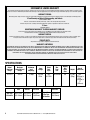
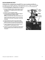
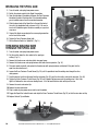
Part #12012
MIG
175
WELDER
ASSEMBLY & OPERATING Instructions
PDF version available at eastwood.com/12012manual
STATEMENT OF LIMITED WARRANTY
The Eastwood Company (hereinafter “Eastwood”) warrants to the end user (purchaser) of all new welding and cutting equipment (collectively called the “products”) that it
will be free of defects in workmanship and material. This warranty is void if the equipment has been subjected to improper installation, improper care or abnormal operations.
WARRANTY PERIOD:
All warranty periods begin on the date of purchase from Eastwood. Warranty Periods are listed below, along with the products covered during those warranty periods:
3 Year Warranty on Material, Workmanship, and Defects:
• Eastwood MIG 175 Welder
Items not covered under this warranty: Contact tips, nozzles, wire, and ground clamp and cable.
All other components are covered by the warranty and will be repaired or replaced at the discretion of Eastwood.
2 Years:
• All Welding Helmets.
CONDITIONS OF WARRANTY TO OBTAIN WARRANTY COVERAGE:
Purchaser must first contact Eastwood at 1-800-345-1178 for an RMA# before Eastwood will accept any welder returns.
Final determination of warranty on welding and cutting equipment will be made by Eastwood.
WARRANTY REPAIR:
If Eastwood confirms the existence of a defect covered under this warranty plan, Eastwood will determine whether repair or replacement is the most suitable option
to rectify the defect. At Eastwood’s request, the purchaser must return, to Eastwood, any products claimed defective under Eastwood’s warranty.
FREIGHT COSTS:
The purchaser is responsible for shipment to and from Eastwood.
WARRANTY LIMITATIONS:
EASTWOOD WILL NOT ACCEPT RESPONSIBILITY OR LIABILITY FOR REPAIRS UNLESS MADE BY EASTWOOD. EASTWOOD’S LIABILITY UNDER THIS WARRANTY SHALL NOT
EXCEED THE COST OF CORRECTING THE DEFECT OF THE EASTWOOD PRODUCT. EASTWOOD WILL NOT BE LIABLE FOR INCIDENTAL OR CONSEQUENTIAL DAMAGES (SUCH
AS LOSS OF BUSINESS, ETC.) CAUSED BY THE DEFECT OR THE TIME INVOLVED TO CORRECT THE DEFECT. THIS WRITTEN WARRANTY IS THE ONLY EXPRESS WARRANTY
PROVIDED BY EASTWOOD WITH RESPECT TO ITS PRODUCTS. WARRANTIES IMPLIED BY LAW SUCH AS THE WARRANTY OF MERCHANTABILITY ARE LIMITED TO THE
DURATION OF THIS LIMITED WARRANTY FOR THE EQUIPMENT INVOLVED. THIS WARRANTY GIVES THE PURCHASER SPECIFIC LEGAL RIGHTS.
THE PURCHASER MAY ALSO HAVE OTHER RIGHTS WHICH VARY FROM STATE TO STATE.
SPECIFICATIONS
Output
Amperage
Range
Maximum
Output No Load
Voltage
Maximum
Input
Amperage
30-175 A
30 V DC
22 Amp
Solid
Wire Type
& Diameter
2
Stainless
Input
Voltage
Rated
Duty
Cycle
Wire
Feed
Rate
Welding
Wire
Spool
Sizes
220 VAC
60 Hz
30%
@ 130 A
40-450 IPM
4-8”
Flux Cored
0.023-0.030” 0.023-0.030” 0.030-0.035”
(0.6-0.8mm) (0.6-0.8mm) (0.8-0.9mm)
Wire Sizes
Spool Gun
Wire Type
& Diameter
0.030-0.035”
(0.8-0.9mm)
Eastwood Technical Assistance: 800.544.5118 >> [email protected]
Weight
67 Lbs.
(25kg)
Overall
Dimensions
24.4”
(620 mm) x
12.6”
(320 mm) x
17”
(430 mm)
Duty Cycle
The rated Duty cycle refers to the amount of welding that can be done within an amount of time. It is easiest to look at your welding time
in blocks of 10 Minutes and the Duty Cycle being a percentage of that 10 Minutes. If welding at 130 Amps with a 30% Duty Cycle, within
a 10 Minute block of time you can weld for 3 Minutes with 7 Minutes of cooling for the welder. If the duty cycle is exceeded and the
breaker is tripped, allow the unit to cool for a minimum of 15 Minutes. To increase the duty cycle you can turn down the Voltage Output
control. Going above 130 Amps will yield a lower duty cycle.
Safety Information
ARC WELDING can be dangerous.
THIS WELDING MACHINE MUST BE CONNECTED TO A POWER SOURCE IN ACCORDANCE WITH APPLIANCE ELECTRICAL CODES.
✓
DISCONNECT FROM POWER SOURCE BEFORE ASSEMBLING, DISASSEMBLY OR MAINTENANCE
OF THE TORCH OR CONTACT TIP OR CHANGING WIRE SPOOLS.
FOR SAFETY TURN OFF AND UNPLUG MACHINE WHEN INSTALLING NEW WIRE SPOOL, ADJUSTING WIRE TENSION
ROLLER OR REPLACING CONTACT TIP.
THE GAS NOZZLE MUST ALWAYS BE INSTALLED WHEN WELDING-DO NOT WELD WITHOUT THE GAS NOZZLE IN PLACE.
THE CONTACT TIP IS ELECTRICALLY “HOT” AND IF IT CONTACTS THE GROUNDED WORK PIECE IT WILL CAUSE DAMAGE.
ALL INSTALLATION, MAINTENANCE, REPAIR OPERATION OF THIS EQUIPMENT SHOULD BE PREFORMED BY QUALIFIED
INDIVIDUALS IN ACCORDANCE WITH NATIONAL, STATE AND LOCAL CODES.
ELECTRIC SHOCK CAN KILL! Improper use of an electric welder can cause electric shock, injury and death!
Read all precautions described in this manual to reduce the possibility of electric shock.
1. The MIG175 power switch is to be in the OFF (“0”) position when installing the work cable and gun and while
plugging in the power cord.
2. Always wear dry, protective clothing and leather welding gloves and insulated footwear.
3. Always operate the welder in a clean, dry, well ventilated area. Do not operate the welder in humid, wet, rainy
or poorly ventilated areas.
4. Be sure that the work piece is properly supported and grounded prior to beginning an electric welding operation.
5. The electrode and work (or ground) circuits are electrically “hot” when the welder is on. Do not touch these “hot”
parts with your bare skin or wet clothing.
DO NOT TOUCH THE CONTACT TIP with the unit turned “ON”. Turn the unit off before
changing tips or cleaning the nozzle.
To order parts and supplies: 800.345.1178 >> eastwood.com
3
UNPACKING
When unpacking your Eastwood MIG175, check to make sure all of the parts listed below are included:
• MIG175 Welder
• Torch / Gun Cable Assembly
• Spool Gun Assembly
• Ground Cable Assembly
• Gas Flow Regulator
• Gas Hose
• Hand Held Shield
• Wire Brush
• 2lb Spool of 0.030” (0.8mm) Solid Steel MIG Wire
• 1lb Spool of 0.030” (0.8mm) 4043 Aluminum Wire
• 2 Contact Tips
• Contact Tip Wrench
• Instructions
• DVD
COMPONENTS AND CONTROLS
1. Ground Cable Access Hole
2. MIG Gun/Spool Gun Access Hole
3. Power Switch
4. Voltage Control
5. Wire Speed Control
6. Latch
7. Power Cord
8. Breaker Reset Switch
9. Shielding Gas Inlet
10.Rocker Arm
11.Pressure Adjuster
12.Guide Pipe
13.Torch Tensioner
14.Positive Terminal
15.Negative Terminal
4
16.Wire Tension Thumb Screw
17.Wire Spindle
18.Contact Tip
19.Nozzle
20.Ground Clamp
21.Trigger Connections
22.Drive Roller
23.MIG Torch
24.Spool Gun
25.MIG Gun/Spool Gun Selector Switch
26.Regulator
Eastwood Technical Assistance: 800.544.5118 >> [email protected]
✓
✓
✓
3
4
5
✓
24
21
✓
✓
23
✓
2
20
6
✓
26
1
✓
19 18✓
✓
8
14
✓
✓
25
15
✓
11
7
✓
10
✓
✓
✓
✓
16
To order parts and supplies: 800.345.1178 >> eastwood.com
17
12
22
13
✓
✓
✓
✓
9
✓
5
INSTALLATION
FIG. A
INSTALLING THE WELDING GUN
3A
✓
1. Open the side door of the welder and loosen the Torch Tensioner (Fig. 1B)
located on the Drive Motor.
2. Slide the brass body of the Welding Gun in through the front of the unit in
the designated hole. (Fig. 1A) Be sure to insert until it bottoms against
the drive assembly or a gas leak may occur.
3. Connect the black cannon plug to the cannon plug connection on the
front of the welder. (Fig. 3A)
4. Tighten the Torch Tensioner (Fig. 1B) finger tight.
5. Switch the selector switch to the Welding Gun position. (Fig. 2B)
NOTE: Make sure that the gun end is tight against the drive assembly
or gas may either leak or not be able to pass through the connections
to the end of the Welding Gun.
1A
✓
2A
FIG. B
2B
INSTALLING THE Ground Clamp
1. Insert the terminal connection of the Ground clamp through the
designated hole in the front of the unit. (Fig. 2A)
2. Pull the cable through and route it though the wire loom located on
the back side of the front panel. (See Fig. C for routing)
3. Remove the Black Ground Knob and install the wire terminal on the stud.
4. Reinstall the Black Ground Knob and finger tighten.
Changing Polarity
1B
FIG. C
6
Polarity for
Flux-Cored
Welding
Eastwood Technical Assistance: 800.544.5118 >> [email protected]
Polarity for
MIG Welding
FIG.E
FIG.D
✓
The Eastwood MIG175 comes set up to weld with Solid Wire, to use a
Flux Cored wire the Polarity must be changed.
1. Disconnect the wire lead coming from the Drive Motor by removing
the Red Positive Knob.
2. Remove the lead from the stud.
3. Remove the Black Ground Knob and its associated lead.
4. Install the lead from the drive motor onto the Negative (-) Stud
and replace the Black Ground Knob.
5. Install the lead from the ground clamp onto the Positive (+) Stud
and replace the Red Positive Knob.
✓
To order parts and supplies: 800.345.1178 >> eastwood.com
A Shielding Gas Bottle is not included with your Eastwood MIG175 but is necessary to welding using Solid Wire, but
can be bought at most local Welding Supply Stores. Eastwood recommends the use of 75% Argon / 25% CO2 for shielding
gas when MIG welding Steel, 100% Argon for Aluminum, and Tri-Mix (90% He / 7.5% Ar / 2.5% CO2) for Stainless Steel.
1. Place the Eastwood MIG175 in its dedicated area or on a welding cart.
2. Secure your Shielding Gas Bottle to a stationary object or mount to
Valve Bottle
Gas Flow
your welding cart if it is equipped to hold one so that the cylinder
Pressure
Output
Gauge
cannot fall over.
Gauge
3. Remove the cap from the Shielding Gas Bottle.
Flow
Regulator
4. Insert the large brass male fitting on the Shielding Gas Regulator
into the female fitting on the Shielding Gas Bottle.
Hose feeds
NOTE: Do not use White Teflon Tape on this connection as it is a
to gas input
tapered thread and does not require it, if you have a leak check
for burrs or dirt in the threads. If the leak persists, use gas type
sealing tape.
FIG. F
5. Tighten the fitting with a wrench till snug, do not over tighten.
6. Connect either end of the Gas Line included with your Eastwood
MIG175 to the fitting on the regulator and wrench tighten till snug.
7. Connect the other end of the gas line to the fitting on the rear of
the Eastwood MIG175 and wrench tighten till snug.
8. Check the gas line for leaks by slowly opening the valve on the gas
bottle. When welding the valve on the bottle should always be all
the way open.
✓
Installing shielding gas supply
7
Installing Wire Spool
The Eastwood MIG175 can be used with either a 4”or an 8” Wire Spool. To use the larger 8” spool an included adaptor is necessary.
To install a 4” Wire Spool:
1. Open the door of the welder and remove the wing nut (Fig. 2G), spacer (Fig. 1G), and 8in Spool Adaptor (Fig. 3G)
from the Wire Spool Spindle.
2. Slide the 4” Wire Spool onto the spindle and reinstall the spacer and the wing nut and place the 8in Spool Adaptor
(Fig. 3G) in a safe place if it is needed in the future.
3. To set the tension on the wire, tighten the wing nut till there is a slight resistance to spinning
FIG. G-1
the wire spool on the spindle. If the tension is set too loose the wire spool will spin on the
shaft and unspool all of the wire. If the tension is too tight, the drive roller will have issues
pulling the wire off the spool and some slipping may occur.
NOTE: Hold exposed wire end to keep the spool from unraveling.
To install an 8” Wire Spool:
1. Open the door of the welder and remove the wing nut, spacer, and 8” Spool Adaptor
from the Wire Spool Spindle.
FIG. G-2
2. Slide the 8” Wire Spool Adaptor into the center of the wire spool.
3. Slide the 8” Wire Spool Adaptor with the wire spool installed onto the spindle and
reinstall the spacer and the wing nut.
4. To set the tension on the wire, tighten the wing nut till there is a slight resistance to spinning
the wire spool on the spindle. If the tension is set too loose the wire spool will spin on the shaft
and unspool all of the wire. If the tension is too tight, the drive roller will have issues pulling the
wire off the spool and some slipping may occur.
1G
✓
The Eastwood MIG175 welder requires a dedicated 220 VAC 30 Amp grounded outlet protected by a time delay breaker.
The MIG175 is equipped with a NEMA 6-50P Plug which requires a NEMA 6-50R outlet to be connected.
Threading Welding Wire Through The
Drive MOTOR To The Welding Gun
FIG. H
1. Unlock the Pressure Adjuster (Fig. 1H) on the wire tensioner and
lift up the rocker arm (Fig. 2H). Insure that the wire drive wheel
is appropriate to the welding wire size, see above describing the
2H
installation to wire feed roller installation.
1H
2. Pull out the welding wire (Fig. 3H) from the welding wire spool
carefully. NOTE: Do not let go of the wire prior to step 5 or
the entire spool will unravel and be useless.
3. Cut off the small piece of the curved segment at the front of
3H
welding wire and straighten the welding wire approximately
6H
3.0” long.
5H 4H
4. Thread the welding wire through the guide pipe (Fig. 4H) and over
the wire feed roller (Fig. 5H) and into the torch hole (Fig. 6H).
5. Reattach the rocker arm (Fig. 2H) and reset the Pressure Adjuster (Fig. 1H) on the wire feeder (now the welding wire can
be fed smoothly).
6. Remove the contact tip and nozzle from the MIG Gun.
7. Turn on the machine and set the wire speed about 1⁄2 on the scale.
8. With the gun pointed away from you and others, depress the trigger to begin feeding wire. NOTE: Watch the drive roller
to see if any slipping is occurring between the roller and the wire—if so turn the machine off and tighten the Pressure Adjuster
✓
✓
Eastwood Technical Assistance: 800.544.5118 >> [email protected]
✓
✓
✓
8
3G
✓
Connecting the Welder to a Power Source
2G
1. 1⁄4 turn and test again.
2. You do not want too much tension on the tension roller as it will tend to deform the wire. Just enough to feed
the wire without slipping
3. Once the wire has emerged from the tip of the gun, turn the machine OFF and replace the tip and nozzle.
Shielding Gas Flow Adjustment
After connecting your Shielding Gas Regulator, the gas flow rate needs to be adjusted so that the proper amount of Shielding Gas
is flowing over your weld. If there is too little gas flow there will be porosity in your welds as well as excessive spatter, if there is
too much gas flow you will be wasting gas and may affect the weld quality. The included regulator has 2 gauges on it; the gauge
on the left is your flow rate while the gauge on your right is your tank pressure.
1. Open your Shielding Gas tank valve all the way.
2. Adjust the knob on the regulator to ~30 CFH.
3. Turn on the welder and trigger the torch switch which will start the gas flow.
4. As you trigger the torch switch you will notice that as the gas flow starts the needle on the gauge drops to a steady reading.
The reading while flowing is the value you want to read.
5. The gas flow should be set to ~20CFH while flowing. The CFH (Cubic Feet per Hour) scale is the inside scale in red on your
flow gauge. 20CFH is the most typical flow rate but it may need to be adjusted in some cases depending if there is a slight
breeze or some other instance where additional shielding gas is required to prevent porosity in the weld.
6. When finished welding remember to close the gas valve on the bottle.
Changing The Driver Roller
✓
The wire feed drive roller on the drive motor has 2 grooves, one for 0.023” (0.6mm) welding wire and another for 0.030” (0.8mm)
or 0.035” (0.9mm) welding wire. Your MIG175 comes with the drive roller pre installed for using 0.030” (0.8mm) wire. In the event
that 0.023” welding wire is to be used, the wire feed roller needs to be changed.
1. Turn off the welder and unplug the welder from power.
2. Unlock the Tensioner (Fig. 1I) by pulling it towards you.
FIG. I
3. Lift the Rocker Arm (Fig. 2I) up and rotate out of the way.
4. Remove the star knob (Fig. 3I) by loosening it by hand.
5. Slide the drive roller off the shaft.
6. Determine which size wire is going to be used and slide the
drive roller back onto the shaft by aligning the key on the shaft
with the keyway on the roller.
1I
3I
9
✓
To order parts and supplies: 800.345.1178 >> eastwood.com
2I
NOTE: The stamped marking on the side of the drive roller indicates
the size of the groove on the opposite side of the roller. The groove
closest to the drive motor is the groove that will be used. If setting up
to use 0.023” (0.6mm) wire, the ‘0.6’ stamping should be facing the
user when installing it.
7. Tighten the star knob finger tight.
8. Push the rocker arm back down into place.
9. Lift up on the Tensioner to put back in place and adjust as
necessary.
INSTALLING THE SPOOL GUN
FIG.J
1. Turn off welder and unplug from power source.
2. Switch the selector switch to the Spool Gun position.
3. Open the side door of the welder and loosen the Torch Tensioner
located on the side of the drive roller. If the standard welding
gun is installed remove it and its associated connector.
4. Slide the brass body of the Spool Gun in through the front of
the unit in the designated hole as shown in Fig. J. Be sure to
insert until it bottoms against the drive assembly or a gas leak
may occur.
5. Connect the black cannon plug to the cannon plug connection
on the front of the welder.
6. Tighten the Torch Tensioner finger tight.
7. Set the Selector Switch to “Spool Gun” (Fig. 1J)
1J
✓
THREADING WELDING WIRE
THROUGH THE SPOOL GUN
1. Turn off welder and unplug from power source.
✓
✓
✓
✓
2. Set the switch above the drive motor to the spool gun
setting. (Fig. 1J)
3. Remove the thumb screw and clear plastic wire spool cover.
4. Remove the thumb screw and spring tensioner that holds the wire spool on. (Fig. 1K)
5. Place wire spool on spindle and replace the thumb screw with spring tensioner and tighten till the point that the
spool has some tension on it.
6. Loosen the Brass Tensioner Thumb Screw (Fig. 2K) until it is possible to feed the welding wire through the drive
roller grooves.
7. Feed the wire by hand from the spool into the inlet guide, (Fig. 3K) past the drive rollers and into the wire inlet. (Fig. 4K)
8. Tighten the Brass Tensioner Thumb Screw (Fig. 2K) until it applies light pressure onto the welding wire. If this is too
tight it will deform the wire and cause feeding issues, if it is too loose the drive roller will slip on the wire.
9. Remove the nozzle and contact tip.
10.Replace the wire spool cover.
11.Plug in welder to your power source and turn on the welder.
12.Trigger the Spool Gun to feed the wire and adjust the Brass Tensioner Thumb Screw (Fig. 2K) so that the wire does not slip.
13.Replace Contact Tip and Nozzle.
1K
FIG.K
10
3K
2K
4K
Eastwood Technical Assistance: 800.544.5118 >> [email protected]
Operation
Welding Process
Your Eastwood MIG175 can be used to form a large number of different joints and welds all of which will require
practice and testing before using on an actual project piece. This following welding process is just a baseline to
get you started.
1. Refer to the ‘Suggested Settings’ chart which is located inside the side door of your Eastwood MIG175 as well
as below in the instruction manual. From the chart select your baseline starting point for the recommended
settings described in the chart.
2. Change the output polarity if necessary according to the welding wire’s specifications. This welder comes set
up to use Solid MIG wire, if using Flux Cored wire, the polarity will need to be changed.
3. Connect your ground clamp to the work pieces that are to be welded. Make sure the ground clamp contacts
are placed on a clean piece of metal free of paint, grease, rust, oils, etc. It is recommended to place your
ground clamp as close to the weld area as possible.
4. Assess your weld area and make sure the welding area is also cleaned of any paint, grease, rust, oils, etc.
5. Plug in the welder and switch to the ON position.
6. Open your gas valve on the bottle and adjust the flow rate if necessary.
7. Depress the torch trigger pointing the welding gun away from your body and then let go of the trigger and
cut the wire back to ~1/4” stick out length.
8. Wearing your welding helmet, gloves, and long sleeve shirt and pants, put the end of the wire sticking
out of the gun into the joint to be welded.
9. Position the welding gun so that it is perpendicular to the base metal with ~20° tilt back.
10.Depress the trigger to start the wire feed which starts the arc. NOTE: A push, perpendicular, or drag
technique can be used to weld the pieces together; the type used depends on the type of joint as well
as other influential conditions.
11.Once you depress the trigger and the arc has started, you will notice a molten puddle will form; this puddle
is the weld bead and will follow the motion of the welding torch. Watching the size of the puddle dictates how
fast you should be moving with the torch. If you burn through the material you are either moving to slow or you
need to make some setting adjustments to the welder settings. If you’re not penetrating the base metal you’re
either moving too fast or you need to make adjustments to the welder settings.
12.Release the trigger on the welding gun to stop the weld.
13.After finished welding, close the valve completely on the Shielding Gas Bottle.
To order parts and supplies: 800.345.1178 >> eastwood.com
11
Types of Weld Joints
1. Butt Weld is a joint between two pieces that are laying in
the same direction.
2. Corner Weld is a joint between two pieces that meet at
or near perpendicular at their edges.
3. Edge Weld is a joint between two pieces where the
edges are being joined.
4. Lap Weld is a joint between two overlapping pieces.
5. Tee Weld is a joint between two pieces where one is
perpendicular to the other.
6. Plug Weld is a joint which joins two overlapping pieces
by filling in a hole punched in the top piece.
12
Eastwood Technical Assistance: 800.544.5118 >> [email protected]
Sheet Metal Welding Techniques
When welding sheet metal a different approach is usually taken to account for how thin the metal is and it’s susceptible to
warping it is. The technique most often used is called Stitch Welding and this process is described below:
1. Clean the metal to be welded of any paint, rust, oil, grease, dirt or any other contaminants that may be on the surface of the piece.
2. Secure the pieces to be welded in place using clamps. Be sure to leave a small gap between the two pieces of sheet
metal for the weld to flow into, this will result in a lower bead height which will require minimal finishing.
3. Consult the Suggested Settings Chart and set the Voltage and Wire Speed knobs appropriately.
4. Get some pieces of scrap metal of the same thickness and verify that the settings will work for the specific weld you
will be making.
5. Once the settings have been fine tuned tack weld your final pieces in places and remove the clamps if they are in the
way of the weld.
6. The Stitch Welding technique can now be utilized which is basically a series of tacks connecting together. To perform
the technique, trigger the gun to form a tack weld and then continue to trigger on and off the gun making a series of
connected tack welds following along the path of the weld joint. Continue the series of tacks for an inch or so and then
move to a different section of the weld and perform the process there. It is essential to keep moving around to spread
out the heat making sure not to get one section too hot and warp the metal.
7. Once the entire weld has been completed allow the metal to cool. If necessary follow up with a flap disc to grind the
weld bead flush.
Heavy Gauge Metal Welding Techniques
When welding sheet metal, a different approach is usually taken to account for how thin the metal is and it’s susceptible
to warping it is. The technique most often used is called Stitch Welding and this process is described below:
1. Clean the metal to be welded of any paint, rust, oil, grease, dirt or any other contaminants that may be on the surface
of the piece.
2. Secure the pieces to be welded in place using clamps. Be sure to leave a small gap between the two pieces of metal
for the weld to flow into, this will result in a lower bead height which will require minimal finishing.
3. Consult the Suggested Settings Chart and set the Voltage and Wire Speed knobs appropriately.
4. Get some pieces of scrap metal of the same thickness and verify that the settings will work for the specific weld you will be making.
5. Once the settings have been fine-tuned tack weld your final pieces in places and remove the clamps if they are in the
way of the weld.
6. When welding heavy gauge metal there are two basic approaches to creating the weld. The first is a continuous bead
with steady gun movement along the length of the joint. The second type of weld is a Stringer or Weave bead. This is
accomplished by moving the torch in a circular or zig zag pattern. Either of these techniques will create strong welds
but in some cases the Stringer or Weave type will create a more aesthetically appeasing weld bead.
7. Once the entire weld has been completed, allow the metal to cool. If necessary, follow up with a flap disc to grind the
weld bead flush.
Overload Protection
Your Eastwood MIG175 is equipped with a temperature controller as well as an overload breaker. These two protection devices will
protect your welder if the duty cycle is exceeded. If the output is exceeded, the internal breaker will trip and stop power supply to the
drive motor although the fan will still run to cool the unit.
If the breaker tripped resulting from an overload, the circuit breaker button on the rear of the welder will extend out. This circuit
breaker must be reset manually. Before resetting the circuit breaker button allow the welder to cool for a minimum of 15 minutes.
If there is no voltage output and the circuit breaker was not tripped, the internal thermal protector may have shut off the welder until
it cools to normal operating temperature. This is an automatic function and does not require the user to manually reset anything.
To order parts and supplies: 800.345.1178 >> eastwood.com
13
Troubleshooting
!&
%&$"
!)' $(
'%&(!&!'&"'&&!$%&& '%&)$%"&!%&$%&& !)+!'$&$(%"!&) ' %&' $(
%'$&!"'!$$&!& &"'-
!(&! &&&"! &) ' *%%($&'& !%$&!&)!$"&!%!$& &
&!*"!%) )$-
032%$&!$*'
&$!!
& %%!0.1/,* &%)$%'&%
"!!$" &$&! -
) (+'&%&+
%%$+&! $%&) "
!!$
&$$"$&! &) &&)!"% %!(&
%! &)%!&"%-
!&
%&$"
!%
!" !!$ #'
'%&(!&!'&"'&&!!)$%&& '%&)$%"&!%!)$%&& $%+!'$&$(%")&&
) ' !)!&
!)$"
!)' $(
'%&(!&!'&"'&&!!)$%&& '%&)$%"&!%!)$%&& $%+!'$&$(%")&&
) ' )&"% '&"$%&!
"&"%$!"' "$&-
%) "%&!%'$&"% &$"$!"$%"-
!"$( &)$" !)&"&!!!
&$) %%&! %&&-
!(
+!'$) $%$!' + !&!"&+
&) ! %&! &! $&$) %!' & ! $
& !(&! !&$&!%"$!'&&
& &"-
14
Eastwood Technical Assistance: 800.544.5118 >> [email protected]
Troubleshooting
!(!%
!(#"
#%*$%
)$$'#%&%
!$%
!!# $
#! $
#%*$%
)$$'#%&%
$%#"
#%*$%
!!# $
#! $
#! #
)$$'#%&%
To order parts and supplies: 800.345.1178 >> eastwood.com
&$%'!%!&%"&%%!#$%% &$%(#$"%!$%#$%% !'" %,#&$%,!,#$,#%!# *
!%#! % %$%%*! %
$&#!%"-
!'%! %%%"! %( & !$#%!%(!#"%!$!#% %
%!)"!$( (#-
( ! #","#%&#*
$%"$,(($!#!%!%,
%* $$#*%!"#%*!&#"#%
(%%!#-
#$%!(#%!%$ $-
%!%%$%% !( "!#!$%*$
$%#% %!!# %($,% $%%
%!%% $%!#- !%!
*#!$$( $%%*!( %
$ $(*#!%( +! -
$&#%%*!&#&$ 326#! .
1261$! $% 0//6#! ! & &-
!'" %,#&$%,!,#$,#%!# *
!%#! % %$%%*! %
$&#!%"-
!'%! %%%"! %( & !$#%!%(!#"%!$!#% %
%!)"!$( (#-
&$%(#$"%!$!(#$%% !'" %,#&$%,!,#$,#%!# *
!%#! % %$%%*! %
$&#!%"-
#$%!(#%!%$ $-
%!%%$%% !( "!#!$%*$
$%#% %!!# %($,% $%%
%!%% $%!#- !%!
*#!$$( $%%*!( %
$ $(*#!%( +! -
$&#%%*!&#&$ 326#! .
1261$! $% 0//6#! ! & &-
(#!#%*" $&#%$
""#!"#%!#%%# "#!$$
&$-
!'%! %%%"! %( & !$#%!%(!#"%!$!#% %
%!)"!$( (#-
15
ACCESSORIES
Consumable Parts
•
•
•
•
•
•
12211 – 0.023” / 0.6mm Contact Tips (5 Pack)
12224 – 0.030” / 0.8mm Contact Tips (5 Pack)
12210 – Nozzle
12226 – 0.023” Solid MIG Wire, 2lbs, 4” Spool
12227 – 0.030” Solid MIG Wire, 2lbs, 4” Spool
12225 – 0.030” Flux Cored Wire, 2lbs, 4” Spool
Optional Parts
• 12236 – Welding Cart
• 11616 – Deluxe MIG / TIG / Plasma Welding Cart
Apparel
•
•
•
•
•
13203 – Auto Darken Welding Helmet
13212 – Large View Auto Darken Welding Helmet
12957 – Welding Helmet Bag
12589 / 12590 – Top Grain Cowskin 4” Cuff Welding Gloves (M/L)
12762 – L/XL/XXL Welding Jacket
Replacement Parts
Call Eastwood Customer Service at 1-800-343-9353 for assistance with replacement parts.
If you have any questions about the use of this product, please contact
The Eastwood Technical Assistance Service Department: 800.544.5118 >> email: [email protected]
PDF version of this manual is available online >> eastwood.com/12012manual
The Eastwood Company 263 Shoemaker Road, Pottstown, PA 19464, USA
US and Canada: 800.345.1178 Outside US: 610.718.8335
Fax: 610.323.6268 eastwood.com
© Copyright 2012 Easthill Group, Inc.
Instruction part #12012Q
Rev. 10/12