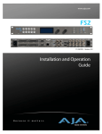
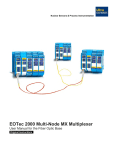
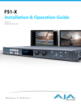
1
Quick Start Guide
Installation Summary
These instructions can help you connect and operate the FS2 quickly. For additional
details, please see the FS2 Installation and Operation Guide on the supplied DVD.
1. Unpack the shipping box, and read the late-breaking news sheet, if any.
2. Install physical options, such as fiber optic modules or Dolby Decoder card (Dolby
Encoder is a future option). AJA Fiber I/O modules slide into the Fiber slots in the
back; use only AJA modules. The Dolby Decoder card mounts inside the top cover
in the right-hand slot as shown below.
FS2 Top View
Remove cover screws
Dolby E Encoder
(future) Option Card
Dolby E Decoder
Option Card
Connectors
Standoffs
Remove cover screws
3. Mount the physical chassis: front rack, rear rack, or deskmount—1 RU x 17.5 inches
(44.45 cm) x 16 inches (40.65 cm). Do not block air flow through the side vents.
4. Connect one or two power cords to the FS2 and mains AC (100-240 VAC, 50/60 Hz,
55 Watts). For redundancy, use both cords and connect them to separate branch
circuits. The FS2 power supply is autosensing and adjusts to the available power.
5. Connect your computer to the FS2 using a CAT5 Ethernet cable to the FS2 RJ45 10/
100/1000 Ethernet LAN connector. You can connect directly or via a network
device such as a switch, hub, bridge, etc. The FS2 automatically senses and adjusts
to either a straight-through or crossover cable.
6. Make signal I/O connections to the FS2 back panel as the following figure shows.
Copyright © 2011 AJA Video Systems Version 1.1.0.0 12/9/2011
2
AES/EBU Digital
Audio In/Out
Channels 1 through 16
DB-25F Connectors
RS422 Machine
Control 15-pin
DB-15F
(Future Upgrade)
Analog Audio In/Out
Channels 1 through 8
DB-25F Connectors
(uses Tascam-style
cable)
AC Power
Socket #1
Autosensing
100 to 240VAC
50/60Hz
10/100/1000
RJ45 Ethernet
LAN Connector
GPI 15-pin
DB-15F Connector
GPI Out 3
GPI Connector Pinout
Ground
NC
RS-485 Dolby Metadata Input +
RS-485 Dolby Metadata Input Ground
1
6
11
1
6
11
Audio Connector Pinout
GPI GND 1
GPI GND 3
GPI In 3
GPI Out 2
GPI In 2
GPI Out 1
GPI In 1
GPI In 4
Ground
GPI GND 2
5
GPI Out 4
Key
G = Ground
+/- = Balanced Pair
Component
External Reference
YPbPr and
I/O with looping
RGB or
BNC connectors.
Composite (v1.1) Use 75-ohm terminator
In/Out
on unused connector
BNC
or downstream equipment.
10
15
NC
GPI GND 4
Composite
In/Out BNC
5
Ground
Serial Digital
In/Out BNC
(3G/SD/HD)
Serial Digital
Fiber In/Out
(3G/SD/HD)
10
15
G - +G - +G - +G - +G - +G - +G - +G - +
HDMI
In/Out
ID
LED
AC Power
Socket #2
Autosensing
100 to 240VAC
50/60Hz
Ground
NC
RS485 Dolby Metadata Output RS485 Dolby Metadata Output +
RS-422 Machine Control Input RS-422 Machine Control Input +
RS-422 Machine Control Output +
RS-422 Machine Control Output Ground
NC
RS422 Connector Pinout
Configuration Summary
The following instructions summarize how to configure the FS2 to communicate over the
web and initially pass video and audio. Using the front panel or browser menus described
later in this guide, you can adapt your FS2 configuration to your specific needs.
1. To begin establishing Ethernet communication so you can use a web browser with
the FS2, check that the IP Config menu is set to DHCP for automatic IP addressing:
Press the FS2 CONFIG button and turn the SELECT knob to display menu 2.1 IP
Config, which should read, DHCP. This setting is the most common and allows your
network to automatically set up FS2 IP addressing. If you prefer to manually set up
addressing, turn the ADJUST knob to change the setting to Static Addr.
2. Next, turn the SELECT knob to display menu 2.2 IP Address and write down the
address if you are using DHCP to automatically assign the address. Later, you will
enter this address in your browser address field to view the FS2 browser menus.
If the FS2 cannot automatically get an address or if you selected Static Addr, the IP
address defaults to 192.168.0.2.
To change the static address, push ADJUST momentarily, and then turn it to
change the blinking octet value. Turn SELECT to advance through the values and
use ADJUST to change each one. When finished setting all octet values, push
ADJUST momentarily to save. To revert at any time to the default address, hold
down ADJUST until the address resets.
FS2 Quick Start Guide — Display Menu Summary
3. You can skip this step if you are using DHCP. If you selected Static Addr in step 1,
turn the SELECT knob to display menu 2.3 Subnet Mask. Change this to match the
Subnet Mask setting in your computer's Network panel/preferences, using the same
procedure described above in step 2 to change the static address.
4. You can skip this step if you are using DHCP. If you selected Static Addr in step 1,
turn the SELECT knob to display menu 2.4 Default Gateway. Change this to match the
Gateway Address setting in your computer's Network panel/preferences, using the
same procedure described above in step 2 to change the static address.
5. Open a web browser on the computer connected to the FS2 and enter the FS2 IP
address in the browser's address field. When the browser connects, the FS2 Status
menu screen appears (shown in “Web Browser Menu Summary” on page 4).
1
6. Configure video and audio I/O as explained in Quick Workflows, “Video and Audio
Right Out of the Box” on page 6, and test the FS2.
If the FS2 is working, configure it for your environment using the menu system. The
following pages summarize the menus, and the FS2 Installation and Operation Guide
on the supplied DVD describes the menus in detail. You can also contact AJA
Technical Support for assistance; please see the contact information at aja.com.
Display Menu Summary
The following illustration and table summarize front panel display operation.
Use buttons to select
a Menu Group
Status
Config System Video 1 Video 2
Turn the Select knob to scroll
through parameter menus.
Push
Select
nam
e to undo changes.
Para m number &
C u rParameter
rent S
etting
Menu
14.1 Output Timing H
M e n Current
u g rSetting
o u p & s t a0t u s
Menu Group & Status
SDI 1
1080i59.94
I n f oInfooorr Prompts
Prompt
Remote Preset Output Audio1 Audio 2
SELECT ADJUST
Turn Adjust to
change current setting.
Hold down Adjust to
restore default value.
Menu Group
Purpose
Parameter Descriptions
STATUS
Status and Error Conditions
• Status of Video 1, Video 2, Caption, Reference, GenLock,
Power, Temperature , and Alarms
REMOTE
FS2 Control Method
• Local front panel, Remote, or Local and Remote Control
• GPI Input and Output behavior
CONFIG
FS2 Configuration
• IP and SNMP settings, MAC address
• Alarm Control
• Hidden Menu Access and Display Intensity (brightness)
• System Name
• System Serial Number and Software Version
• System Reboot
3
4
PRESET
Preset Memory Registers
• Store and Recall Presets
• Factory Preset (recall all defaults)
SYSTEM
Video and Audio Input and
System Settings
• Video and Audio Input Format settings, including 3G input
• Genlock Reference selection; Frame Rates
• NTSC Standard, HDMI and AES sample rate conversion
• Downconversion for HD in to analog composite out
• System Defaults
OUTPUT
Output Sources
• Video and Audio Output selections, including 3G output
VIDEO 1 & 2
Video Processor Inputs, Format,
Conversion Selections and
Adjustments
• Input Sources, background fill, Loss of input setting
• SD input upconversion, HD input downconversion
• Aspect Ratio, H and V timing
• Output Format
• Matte, Proc Amp, Color Corrector, and Legalizer settings
• AFD embedding, input scan (i or p), captioning settings
• Test Pattern selection, Freeze Output
AUDIO 1 & 2
Audio Processor Input Selection
and Adjustments
• Audio input, format, and Audio Follow Video (AFV) selections
• Audio channel and stereo mapping
• Audio level, phase, and delay adjustments
• Audio signal generator selection
Web Browser Menu Summary
The following figure and table summarize web browser menu operation. The
settings generally correspond to the front panel display parameters, providing you
two methods of controlling the FS2. To see the equivalent front panel display
parameter number, hover the cursor over a setting.
List of FS2 Menu Screens
Click a screen's
name to display it.
FS2 Status and Menu Display Area
System info, and FS2 Systems on the network
FS2 Alarms
Click the gear
icon in the headng
to open the alarm menu.
The Network menu also
opens by clicking the gear.
Browser Screen
Purpose
Available Settings
ALARM CONFIG
Alarm Configuration
• Alarm control
NETWORK CONFIG
Network Configuration
• IP address, Subnet Mask, Default Gateway, System Name
FS2 Quick Start Guide — Web Browser Menu Summary
STATUS
Status and Error Conditions
• Status of Video 1 Input, Video 2 Input, Video Input Format,
Video Output Format, GenLock Source, Proc Amp, RGB Color
Corrector
SYSTEM
Video and Audio Input and
System Settings
• Component & Composite Video In/Out Format (SMPTE/Beta)
• 3G Input Settings
• Analog Audio Standard (input/output levels)
• Genlock reference selection
• Frame Rates, NTSC Standard
• Composite Downconversion
• HDMI RGB Range, HDMI Sample Rate Converter Bypass
• AES/EBU Sample Rate Converter Bypass
CONFIG
Configuration
• Display intensity (brightness)
• Show/Hide unused menus
• UPnP Host & Proxy
PRESETS
Preset Memory Registers
• Store and Recall Presets
• Export and Import Preset Files
• Name Each Preset register
• Recall Factory Preset (recall all default values)
OUTPUT
Output Sources
• Video and audio output selections and formats
• 3G Output selection
VIDEO 1 & 2
Video Processor Inputs, Format,
Conversion Selections and
Adjustments
• Input Sources
• Output Format and Mode
• Background Fill, Loss of Input settings
• Conversion settings: Up, Down, Aspect, Edge, Custom
• Matte settings
• Proc Amp, Color Corrector
• Custom positioning
• H & V output timing
• Legalizer settings
• AFD embedding
• Scan Format (i or p)
• Caption settings
• Test Pattern Video Output, Freeze Output
AUDIO 1 & 2
Audio Processor Input Selection
and Adjustments
• Audio Processor input selection, format
• Audio channel and stereo mapping
• Audio embedding
• Audio Follow Video (AFV)
• Audio level, phase, and delay adjustments
• Audio Signal Generator selections
REMOTE
Remote Control and GPIs
• Local and/or remote control settings
• GPI Input and Output configuration
FIRMWARE
Firmware Update
• Browse, select, and install firmware updates
1
5
6
Quick Workflows
The following workflows will help you quickly put the FS2 to use and get the most value.
Canned Presets
to Give You a
Quick Start
AJA plans to create a variety of preset configurations you can import and use to recall the
FS2 to commonly used configurations. This may save you considerable time compared to
setting up configurations manually. You will find these presets on the aja.com FS2 web
page when they become available:
http://www.aja.com/support/converters/converters-fs2.php
Additionally, the following workflows are provided to help you quickly do manual setups.
Video and
Audio Right
Out of the Box
The following quick workflow enables you to get video and audio through the FS2 as
soon as you get it out of the box and make video connections. In the following
procedures, where the terms select and adjust are used, turn the Select and Adjust knobs.
The factory setup is:
• SDI 1 Input feeds Video Proc 1 feeds SDI 1 Output.
• SDI 2 Input feeds Video Proc 2 feeds SDI 2 Output.
The parameter settings are:
• Output Format set to Follow Input.
• Video Input set to SDI 1 and SDI 2.
• Frame Rate set to 59.94/23.98.
• Genlock source set to Reference.
The menu operations for this setup are:
1. Press the Video 1 button.
a. Select 2 Output Format, and adjust to Follow Input.
b. Select 1 Video Input, and adjust to SDI 1.
2. Press the Video 2 button.
a. Select 2 Output Format, and adjust to Follow Input.
b. Select 1 Video Input, and adjust to SDI 2.
3. Press the System button.
a. Select 8 Genlock source, and adjust to Reference.
b. Select 9 Frame Rates, and adjust to 59.94/23.98.
4. Press the Output button.
a. Select 1.1 SDI 1 Video Out, and adjust to Video Proc 1.
b. Select 1.2 SDI 2 Video Out, and adjust to Video Proc 2.
5. Cable the SDI video into the SDI 1 & SDI 2 inputs.
6. Monitor any output for video and audio.
FS2 Quick Start Guide — Quick Workflows
SDI 1 Test
Signal Outputs
The following two workflows produce bars and tone outputs and ramp and silence outputs
The setup is:
• Test signals are switched in at the FS2 outputs, so no particular input settings are
required.
The parameter settings are:
• No settings required.
Menu operations for SDI 1 Out Bars and Tone:
1. Press the Video 1 button.
2. Select 3 Video 1 Output Mode, and adjust to Test Pattern.
3. Select 20 Video 1 Test Pattern Video and adjust to 75% Bars.
4. Press the Audio 1 button.
5. Select 4 Audio Signal Gen and adjust to 1 kHz tone.
Menu operations for Ramp and Silence:
1. Press the Video 1 button.
2. Select 3 Video 1 Output Mode, and adjust to Test Pattern.
3. Select 20 Video 1 Test Pattern Video and adjust to Ramp.
4. Press the Audio 1 button.
5. Select 4 Audio Signal Gen and adjust to Off.
1
7
8
Sidebar Video
The following quick workflow shows you how to create sidebar edges filled with video.
The setup is:
• SDI 1 Input feeds Processor 1 foreground.
Use an SD 525 input on SDI 1; it will be upconverted to 1080i59.
• SDI 2 Input feeds Processor 2, which will provide Processor 1 background.
Use an HD input signal in SDI2.
• Processor 1 feeds SDI1 Output (center video with sidebar video).
• Processor 2 feeds SDI2 Output (showing the sidebar video signal alone).
The parameter settings are:
• Video 1 Input set to SDI 1.
• Output Format set to 1080i59.94.
• Video Output Mode set to Normal.
• Upconvert Mode set to 4x3 Pillar.
• Custom Size/Pos set to Off.
• Background Fill set to Video 2.
The menu operations for this workflow are:
1. Press the Video 1 button.
a. Select 1 Video 1 Input, and adjust to SDI 1.
b. Select 2 Output Format, and adjust to 1080i59.94.
c. Select 3 Video Output Mode, and adjust to Normal.
d. Select 6 Upconvert Mode, and adjust to 4x3 Pillar.
e. Select 4 Background Fill, and adjust sidebar video to Video 2.
e. Select 9 Sidebar Edge, and adjust sidebar position as you prefer.
g. Select 13.0 Custom Size/Pos, and adjust to Off.
2. Press the Video 2 button.
a. Select 1 Video 2 Input and adjust to SDI2.
b. Select 2 Output Format and adjust to 1080i59.94.
FS2 Quick Start Guide — Quick Workflows
Picture Overlay
The following workflow shows how to create a video box overlaying another video source.
The setup is:
• Video Processor 1 input set to SDI 1 (any format).
The parameter settings are:
• Video 1 Input set to SDI 1.
• Output Format set to 1080i59.94.
• Video Output Mode set to Normal.
• Upconvert Mode set to 4x3 Pillar.
1
• Custom Size/Pos set to On.
• Custom Size, Aspect, H&V Position, Left/Right/Top/Bottom Crop as preferred.
The menu operations for this workflow are:
1. Press the Video 1 button.
a. Select 1 Video 1 Input, and adjust to SDI 1.
b. Select 2 Output Format, and adjust to 1080i59.94.
c. Select 3 Video Output Mode, and adjust to Normal.
d. Select 6 Upconvert Mode, and adjust to 4x3 Pillar.
e. Select 13.0 Custom Size/Pos, and adjust to On.
f. Select 13.1 Custom Size, and adjust to10% to 200%.
g. Select 13.2 Custom Aspect, and adjust aspect ratio as preferred.
h. Select 13.3/13.4 Custom H Pos/Custom V Pos, and adjust H & V box position.
i. Select 13.5–13.8 Custom Left/Right/Top/Bottom Crop, and adjust box edges.
9
10
Letterbox Top
The following workflow downconverts a 1080i SDI input, using Letterbox mode, and
shifts the letterboxed video to the top of the screen, leaving the bottom of the screen
available.
The setup is:
• SDI1 input feeds Processor1 Foreground
• Use an HD (1080i) input signal on SDI1, which will be downconverted to 525i.
• Processor 1 feeds SDI1 Output.
• Downconvert Mode is set to Letterbox. Custom V Pos is set to 12.5% to shift the
letterbox to the top of the screen.
The menu operations for this workflow are:
1. Press the Preset button.
a. Select 3 Factory Preset.
b. Hold down the ADJUST knob for three seconds.
2. Press the Video 1 button.
a. Select 1 Video 1 Input, and adjust to SDI 1.
b. Select 2 Output Format, and adjust to 525i59.94.
c. Select 3 Video Output Mode, and adjust to Normal.
c. Select 4 Background Fill, and adjust to Matte.
d. Select 7 Downconvert Mode, and adjust to Letterbox.
e. Select 13.0 Custom Size/Pos, and adjust to On.
f. Select 13.4 Custom V Pos, and adjust to 12.5%.
g. Optional: To fill the bottom portion of the screen with video, select 4 Background
Fill, and adjust to Video2 (ALARM LED will light).
3. Press the Video 2 button.
a. Select 2 Output Format, and adjust to Follow Video1 (ALARM LED will
extinguish).
FS2 Quick Start Guide — Quick Workflows
Dual Stream 3G
Input/Output
"Dual Stream 3G SDI" means two separate and distinct HD video signals are muxed
together into one 3G SDI signal. (By definition, a "Dual Stream 3G SDI" is a "Level B' 3G SDI.)
The FS2 supports this mode, both at the inputs and the outputs. Also, Dual Stream 3G
automatic operation (signal detection) is possible if proper Format ID is present, or you can
set up Dual Stream 3G manual operation if Format ID is not available.
Dual Stream 3G Video Inputs
The FS2 inputs support Dual Stream 3G SDI Inputs by applying the Dual Stream 3G video to
SDI 1 In and making the second video stream appear in the input crosspoint matrix as SDI 2.
In this case, the SDI 2 input connector is unused.
1
1. Connect a (multiplexed) Dual Stream 3G SDI signal to SDI 1 In.
2. Press the System button, select 4 SDI1 3G Detect, and adjust to Auto Detect or Dual Stream.
3. Select 5 SDI2 Input Protect, and adjust to Dual Stream.
Now both HD signals from a Dual Stream 3G SDI input are available as SDI1 or SDI 2, and
either input can be selected for use in Processor 1 or Processor 2. The Fiber 1 input can also
be used in this way.
Dual Stream 3G Video Outputs
Two separate 1.5 Gb HD video signals, one from Processor 1 and one from Processor 2, can
be combined at the FS2 output into one (muxed) Dual Stream 3G SDI signal. The Dual
Stream 3G output can be selected at the four SDI outputs: SDI 1, SDI 2, Fiber 1, or Fiber 2.
1. Press the Output button.
2. Select one of these menus to specify which output(s) will produce Muxed 3G video:
SDI 1 Out: Select 1.1 SDI1 Video Output, and adjust to Proc1+Proc2.
SDI 2 Out: Select 1.2 SDI2 Video Output, and adjust to Proc1+Proc2.
Fiber 1 Out: Select 2.1 Fiber1 Video Output, and adjust to Proc1+Proc2.
Fiber 2 Out: Select 2.2 Fiber2 Video Output, and adjust to Proc1+Proc2.
11
12
Dual Stream 3G
Inputs to
Separate SDI
Outputs
The previous workflow showed you how to use Dual Stream 3G in and produce Dual
Stream 3G out. This variation shows you how to input (muxed) Dual Stream 3G and
demux it to produce separate SDI outputs.
The setup is:
• Apply Dual Stream 3G video (Level B—two 1080i59 images) to SDI 1 In.
The parameter settings are:
• Video 1 Input set to SDI 1.
• Output Format set to 1080i59.94.
• Video Output Mode set to Normal.
The menu operations for this workflow are:
1. Press the System button.
2. Select 4 SDI1 3G Detect, and adjust to Auto Detect or Dual Stream.
(Note that Auto Detect uses the SMPTE 352 embedded Format ID data stream to
automatically detect Dual Stream 3G video.)
3. Select 5 SDI2 Input Protect, and adjust to Dual Stream 3G.
4. Press the Video 1 button, select 2 Output Format, and adjust to 1080i59.94.
5. Select the Output button, select 1.1 SDI1 Video Out, and adjust to Processor 1.
6. Press the Video 1 button, select 1 Video 1 In, and adjust as follows:
a. Adjust to SDI1 (display bottom line shows SDI1-1). The SDI 1 Output is now
1080i59.94 stream 1 of the input video.
b. Adjust to SDI2 (display bottom line shows SDI1-2). The SDI 1 Output is now
1080i59.94 stream 2 of the input video.
As you can see, using the ADJUST knob, you can select which stream of the Dual
Stream 3G input video you want to see at the SDI 1 Output.
The two demuxed video streams are also available at the other outputs—SDI 2,
Fiber 1, and Fiber 2 if you switch those outputs to show the desired input stream.
FS2 Quick Start Guide — Additional Notes
Additional Notes
This section contains additional notes to help you take best advantage of FS2 features.
Interaction of
Presets and GPIs
If you use a GPI input trigger to recall a preset, the recall changes the GPI IN Response
setting to whatever GPI IN Response setting the preset contains. As the following examples
explain, this feature offers both the power of serial recalls and the possibility of triggering a
recall that changes GPI IN Response to something unintended.
Example of a Serial Recall
The advantage of using GPI IN Response with presets is that you can trigger a series or even
a looping series of preset recalls. For example, suppose GPI IN 1 Response in Preset 1 is set to
1 will toggle
Preset 2, and GPI IN Response in Preset 2 is set to Preset 1. Triggering the GPI
between the two presets.
Example of an Unintended Recall
Suppose you trigger GPI IN 1 while the current GPI IN 1 Response parameter is set to Preset 1.
This recalls Preset 1 as expected. However, suppose Preset 1 contains a stored GPI IN 1
Response setting of No Action. If you trigger GPI IN 1 later, expecting to recall Preset 1 again,
the FS2 instead performs No Action. To prevent unexpected changes in the GPI IN Response
parameters, set these parameters as desired before storing presets; in the example, set GPI
IN 1 to Preset 1 before you store Preset 1.
For details of preset and GPI input operations, see the Presets menu and browser screen
topics in the FS2 Installation and Operation Guide.
13
14