1
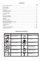
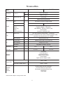
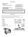
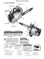
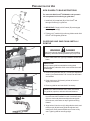
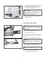
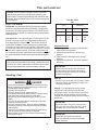
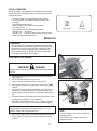
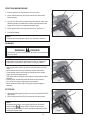
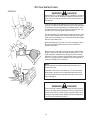
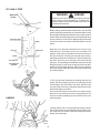
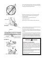
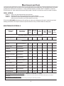
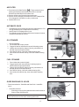
Chain Saw
Instruction Manual
MODELS :
CS-330T
CS-360T
WARNING
DANGER
Read rules for safe operation and instructions carefully. ECHO provides an Instruction
Manual and a Safety Manual. Both must be read and understood for proper and safe
operation.
X7503242004
X750007744
06/06
RULES FOR SAFE OPERATION
A. Kickback Safety Precautions for Chain Saw Users
WARNING!
KICKBACK may occur when the nose or tip of the
guide bar touches an object, or when the wood
closes in and pinches the saw chain in the cut.
1. With a basic understanding of kickback, you
can reduce or eliminate the element of surprise.
Sudden surprise contributes to accidents.
2. Keep a good firm grip on the saw with both
hands, the right hand on the rear handle, and
the left hand on the front handle, when the engine is running. Use a firm grip with thumbs and
fingers encircling the chain saw handles. A firm
grip will help you reduce kickback and maintain control of the saw. Don’t’ let go.
Tip contact in some cases may cause a lightning
fast reverse REACTION, Kicking the guide bar up
and back towards the operator. Pinching the saw
chain along the top of the guide bar may push the
guide bar rapidly back towards the operator. Either of these reactions may cause you to lose control of the saw which could result in serious personal injury.
3. Make sure that the area in which you are cutting is free from obstructions. Do not let the
nose of the guide bar contact a log, branch, or
any other obstruction which could be hit while
you are operating the saw.
®
The Kick Guard device is not installed on the
guide bar when you purchase your ECHO chain
saw. The Kick Guard ® can be used in a majority of
cutting operations, and is especially recommended
for beginners, homeowners, or chain saw novices.
Most cutting operations can be accomplished with
the Kick Guard® in place.
4. Cut at high engine speeds.
5. Do not overreach or cut above shoulder height.
Do not rely exclusively upon the safety devices built
into your saw. As a chain saw user, you should take
several steps to keep your cutting jobs free from
accident or injury.
6. Follow manufacturer’s sharpening and maintenance instructions for the saw chain.
7. Only use replacement bars and chains, or the
equivalent, specified by the manufacturer.
B. Other Safety Precautions
1. Do not operate a chain saw with one hand! Serious injury to the operator, helpers, bystanders, or any combination of these persons may
result from one-handed operation. A chain saw
is intended for two-handed use.
4. Use caution when handling fuel. Move the chain
saw at least 3 m (10 feet) from the fueling point
before starting the engine.
5. Do not allow other persons to be near the chain
saw when starting or cutting with the chain saw.
Keep bystanders and animals out of the work
area.
2. Do not operate a chain saw when you are fatigued.
3. Use safety footwear; snug-fitting clothing; protective gloves; and eye, hearing and head protection devices. Wear protective hair covering
to contain long hair.
6. Do not start cutting until you have a clear work
area, secure footing, and a planned retreat path
from the falling tree.
Copyright© 2006 By Echo, Incorporated
All Rights Reserved.
2
7. Keep all parts of your body away from the saw
chain when the engine is running.
14. Keep the handles dry, clean, and free of oil or
fuel mixture.
8. Before you start the engine, make sure that
the saw chain is not contacting anything.
15. Operate the chain saw only in well-ventilated
areas.
9. Carry the chain saw with the engine stopped,
the guide bar and saw chain to the rear, and
the muffler away from your body.
16. Do not operate a chain saw in a tree unless
you have been specifically trained to do so.
17. All chain saw service, other than the items listed
in the Instruction Manual maintenance instructions, should be performed by competent chain
saw service personnel. (For example, if improper tools are used to remove the flywheel
or if an improper tool is used to hold the flywheel in order to remove the clutch, structural
damage to the flywheel could occur and could
subsequently cause the flywheel to burst.)
10. Do not operate a chain saw that is damaged,
improperly adjusted, or not completely and
securely assembled. Be sure that the saw
chain stops moving when the throttle control
trigger is released.
11. Shut off the engine before setting the chain saw
down.
12. Use extreme caution when cutting small size
brush and saplings because slender material
may catch the saw chain and be whipped toward you or pull you off balance.
18. When transporting your chain saw, use the
appropriate guide bar scabbard.
19. Spark arrestor mufflers approved to SAE Standard J335b are Standard on ECHO Chain
saws to reduce the possibility of forest fires.
Do not operate the chain saw with a loose or
defective muffler. Do not remove the spark arrestor screen.
13. When cutting a limb that is under tension, be
alert for spring back so that you will not be
struck when the tension in the wood fibers is
released.
WARNING
•
•
•
•
•
DANGER
During operation, the muffler or catalytic muffler and surrounding cover become hot.
Never suspend the saw on a lanyard with the engine running.
Always use the saw from the right-hand side of your body – NEVER from the left side.
Always wear proper safety clothing to protect your lower body from sharp saw chain and hot
muffler.
Always keep exhaust area clear of flammable debris during transportation or when storing,
otherwise serious property damage or personal injury may result.
WARNING
DANGER
Using improper replacement components or removing safety devices may result in serious or fatal injury.
3
CONTENTS
Page
Rules for Safe Operation .................................................................................................. 2
Technical Data ................................................................................................................. 5
Emission Data ................................................................................................................. 6
Description ...................................................................................................................... 6
Nomenclature of Parts ...................................................................................................... 7
Preparation for Use .......................................................................................................... 8
Fuel and Lubricant.......................................................................................................... 10
Operation ....................................................................................................................... 11
Starting Cold Engine ...................................................................................................... 11
Starting Warm Engine .................................................................................................... 12
Stopping ........................................................................................................................ 12
Cutting Instructions ......................................................................................................... 13
Maintenance and Care ................................................................................................... 16
Chain and Guide Bar Combinations ............................................................................... 19
Setting the Saw Chain .................................................................................................... 20
Troubleshooting .............................................................................................................. 21
Storage .......................................................................................................................... 24
Correct Use of Chain Brake ........................................................................................... 24
Servicing Information ...................................................................................................... 28
INTERNATIONAL SYMBOLS
Symbol form/shape
Symbol description/application Symbol form/shape Symbol description/application
Chain oil fill
Read and understand
Operator's Manual.
Wear eyes, ears and head
protection
Chain oil pump
Chain brake operation
Chain oiler adjustment
Emergency stop
Carburetor adjustment
- Low speed mixture
Choke control “Cold Start”
position (choke closed)
Carburetor adjustment
- High speed mixture
Gasoline and oil mixture
Carburetor adjustment
- Idle speed
STOP
4
TECHNICAL DATA
CS-330T
Model
Dimension
Weight
LxWxH
Power head, dry
mm
277 x 247 x 214
inch
10.9 x 9.7 x 8.4
kg
3.6 (7.9 lb)
Without chain and guide bar
Type
Air-cooled, two-stroke, single cylinder
Displacement
Engine
32.6 (1.989 cu.in.)
Carburetor
Ignition
Spark Plug
Starter
Power transmission
50:1 ratio with Echo Power Blend TM 2-stroke oil.
89 octane unleaded. Do not use fuel containing methyl alcohol,
more than 10% ethyl alcohol or 15% MTBE.
Fuel
Tank Capacity
ml
310 (10.5 U.S. fl oz.)
Bar and chain
Tank Capacity
36.3 (2.215 cu.in.)
Diaphragm type
Flywheel magneto : CDI system
NGK BPM-8Y - .065 mm (.026 in.) Gap
Recoil starter
Automatic centrifugal clutch
Mixture ratio
Oil
CS-360T
ECHO bar and chain oil (or motor oil)
ml
290 (9.8 U.S. fl oz.)
Lubrication
Adjustable automatic oil pump
Guide bar
Standard
14 in.
16 in.
Saw chain
Optional
12, 16 in.
12, 14 in.
Top Handle
Front hand guard
Anti-vibration device
Throttle control lockout
Chain catcher
Spark arrestor catalytic muffler
Standard
features
Idle
Engine RPM
2,400 - 2,800
Wide Open Throttle (WOT)
13,500 - 14,500
Double Guard Low Kick Guide Bar
Low Kick Guard Link Saw Chain
Front Hand Guard/Chain Brake Lever
Chain Brake
Kick Guard
K i ckb a ck
Safety
Features
* Technical data subject to change without notice.
5
EMISSION DATA
EMISSION CONTROL
EPA Phase 2
IMPORTANT ENGINE INFORMATION
The emission control system for these engines are
EM/TWC (Engine Modification and Catalyst).
ENGINE FAMILY: 6EXHS.0334KB DISPLACEMENT: 32.6 CC
EMISSION COMPLIANCE PERIOD: 300 HOURS
THIS ENGINE MEETS U.S. EPA PH2 AND 2005 - 2006
CALIFORNIA EMISSION REGULATIONS FOR SOREs.
REFER TO OWNER'S MANUAL FOR MAINTENANCE
SPECIFICATIONS AND ADJUSTMENTS.
An Emission Control Label is located on the
engine. (This is an EXAMPLE ONLY, information on
label varies by engine FAMILY).
PRODUCT EMISSION DURABILITY
The 300 hour emission durability compliance period is the time span selected by the manufacturer certifying the engine emissions output meets applicable California and/or U.S. EPA emissions regulations,
provided that approved maintenance procedures are followed as listed in the Maintenance Section of this
manual.
DESCRIPTION
The ECHO product you purchased has been factory pre-assembled for your convenience. Due to packaging
restrictions, guide bar and saw chain installation and other assembly may be necessary.
After opening the carton, check for damage. Immediately notify your retailer or ECHO Dealer of damaged or
missing parts. Use the contents list to check for missing parts.
CONTENTS
111111111111-
Power Head
Guide Bar
Kick Guard
Hex Head Bolt
Hex Nut
Saw Chain
Instruction Manual
Safety Manual
Warranty Registration Card
Limited Warranty Statement
T-Wrench
Echo Power Blend TM 2-stroke oil sample
6
NOMENCLATURE OF PARTS
CS-330T, CS-360T
P/N X5240001710
P/N 89022839131
10
15
P/N X503006550
P/N X503006590
11
12
1
2
3
14
P/N 89019130131
13
4
P/N 89016006361
5
P/N X503006550
P/N X503006590
9
8
7
P/N 89022839131
P/N X505002060
P/N X524001710
P/N 89019130131
REPLACEMENT BAR AND CHAIN
GUIDE BAR*
PART NO.
12” 12AOED3745
14” 14AOED3752
16” 16AOED3757
6
P/N 89016006361
CHAIN*
Note:There may be other replacement
TYPE
LINKS
components for achieving
OREGON 91VG
45
kickback protection. For details,
OREGON 91VG
52
please refer to the chain and bar
OREGON 91VG
57
combination sheet shown in the
instruction manual.
1. Hand guard
(Chain brake actuating lever)
2. Ignition/Choke Lever
3. Throttle control trigger
4. Throttle control lockout
5.
6.
7.
8.
9.
Air cleaner cover
Pull starter
Front handle
Oil tank cap
Fuel tank cap
7
* If a decal cannot be read, a new one can be ordered
from your ECHO dealer.
10. Saw chain
11. Guide bar
12. Sprocket guard
13. Catalytic muffler
14. Spark Plug
15. Rear (Top) Handle
PREPARATION FOR USE
KICK GUARD® TO BAR INSTRUCTIONS
For saws with Kick Guard® P/N 2894901 and symmetrical or asymmetrical low-kick type guide bars.
1. Install bolt (A) in rear hole (B) of Kick Guard® and
through front hole (C) in guide bar.
2. IMPORTANT: Dimple in Kick Guard® (D) must engage
recess in guide bar (E).
3. Tighten nut (F) and bolt (A) until snug. Make certain Kick
Guard® is flush against guide bar.
GUIDE BAR AND SAW CHAIN-INSTALL/
REMOVE
G
WARNING
DANGER
Saw Chain is sharp! Always wear gloves when handling
assembly, otherwise serious personal injury may result.
1. Move chain brake lever (G) fully rearward to unlock chain
brake.
IMPORTANT
K
Always loosen guide bar nuts before turning chain
tension adjuster, otherwise clutch cover and tensioner will
be damaged.
J
H
2. Remove two guide bar nuts (H). Turn tension adjustment
screw (J) counterclockwise 2 to 3 turns if bar and chain
are installed.
M
3. Push clutch cover (K) forward, pull rear of cover out
slightly, then remove.
L
4. Remove guide bar and saw chain if necessary.
NOTE: See “MAINTENANCE AND CARE” instructions
for guide bar, sprocket, and saw chain maintenance.
N
5. Mount guide bar (L) on studs, and slide toward sprocket
to make saw chain installation easier. Install saw chain
(M) over clutch and place around sprocket and guide
bar as shown, with cutters on top of guide bar facing
forward.
6. Align holes of clutch cover (K) with guide bar studs, and
tensioner pin (N) with lower guide bar adjuster hole.
Install cover, then press and hold rear of cover to fully
seat. Tighten guide bar nuts finger tight.
8
7. Turn saw over and check brake band (O) for correct
position around clutch drum (P). If brake band is not
in place around drum, remove clutch cover, make
sure brake is released, and reinstall.
DANGER
P
Never operate saw if chain brake does not
function properly, otherwise saw damage and
serious personal injury could result. See
“Testing the Brake” instructions.
O
8. Adjust saw chain tension, as instructed in “Adjustment, Chain Tension”
ADJUSTMENT, CHAIN TENSION
IMPORTANT
Always loosen guide bar nuts before turning chain
tension adjuster, otherwise clutch cover and tensioner
will be damaged.
1. Remove air filter cover and spark plug lead.
2. Loosen two guide bar nuts (H).
3. Hold the bar nose up, and turn the adjuster screw (J)
clockwise until the chain touches the bottom of the
bar.
J
H
4. Tighten both guide bar nuts with bar nose held up.
IMPORTANT!
Tighten guide bar nuts to 90 – 110 kgf/cm (80 – 95 in.
lbs.) DO NOT over-tighten nuts. Damage to saw
may result.
5. Pull the saw chain around the guide bar by hand.
Reduce chain tension, if you feel tight spots.
NOTE
All chains require frequent adjustments.
6. Keep chain properly tensioned at all times.
7. Replace spark plug lead and air filter cover.
9
FUEL AND LUBRICANT
NOTICE: Use of unmixed, improperly mixed, or fuel older
than 90 days, (stale fuel), may cause hard starting, poor
performance, or severe engine damage and void the product
warranty. Read and follow instructions in the Storage section
of this manual.
Fuel Mix Chart
50:1
FUEL STATEMENT
GASOLINE - Use 89 Octane [R+M/2] (mid grade or higher)
gasoline or gasohol known to be good quality. Gasohol may
contain up to 10% Ethyl (grain) alcohol or 15% MTBE (methyl
tertiary-butyl ether). Gasohol containing methyl (wood) alcohol
is NOT approved.
Two Stroke Oil - A two-stroke engine oil meeting ISO-L-EGD
(ISO/CD 13738) and J.A.S.O. FC Standards must be used.
Echo brand premium Power Blend TM Universal 2-Stroke Oil
meets these standards. Engine problems due to inadequate
lubrication caused by failure to use an ISO-L-EGD and J.A.S.O.
FC certified oil, such as Echo premium Power BlendTM, will void
the two-stroke engine warranty. (Emission related parts only
are covered for two years, regardless of two-stroke oil used, per
the statement listed in the Emission Defect Warranty Explanation.)
IMPORTANT
Echo premium Power BlendTM Universal 2-Stroke Oil may be
mixed at 50:1 ratio for application in all Echo engines sold in
the past regardless of ratio specified in those manuals.
Handling Fuel
WARNING
DANGER
Fuel is VERY flammable. Use extreme care when mixing,
storing or handling or serious personal injury may result.
• Use an approved fuel container.
• DO NOT smoke near fuel.
• DO NOT allow flames or sparks near fuel.
• Fuel tanks/cans may be under pressure. Always loosen
fuel caps slowly allowing pressure to equalize.
• NEVER refuel a unit when the engine is HOT or RUNNING!
• DO NOT fill fuel tanks indoors. ALWAYS fill fuel tanks
outdoors over bare ground.
• DO NOT overfill fuel tank. Wipe up spills immediately.
• Securely tighten fuel tank cap and close fuel container
after refueling.
• Inspect for fuel leakage. If fuel leakage is found, do not
start or operate unit until leakage is repaired.
• Move at least 3m (10 ft.) from refueling location before
starting the engine.
10
(U.S.)
(METRIC)
GAS
OIL
GAS
OIL
Gal.
Fl. oz.
Liter
cc.
1
2
5
2.6
5.2
12.8
4
8
20
80
160
400
Mixing Instructions
1. Fill an approved fuel container with half of the
required amount of gasoline.
2. Add the proper amount of 2-stroke oil to
gasoline.
3. Close container and shake to mix oil with
gasoline.
4. Add remaining gasoline, close fuel container,
and remix.
IMPORTANT
Spilled fuel is a leading cause of hydrocarbon emissions. Some states may require
the use of automatic fuel shut-off containers
to reduce fuel spillage.
After use
• DO NOT store a unit with fuel in its tank. Leaks
can occur. Return unused fuel to an approved
fuel storage container.
Storage - Fuel storage laws vary by locality.
Contact your local government for the laws
affecting your area. As a precaution, store fuel in
an approved, airtight container. Store in a wellventilated, unoccupied building, away from sparks
and flames.
IMPORTANT
Stored fuel ages. Do not mix more fuel than
you expect to use in thirty (30) days, ninety
(90) days when a fuel stabilizer is added.
IMPORTANT
Stored two-stroke fuel may separate.
ALWAYS shake fuel container thoroughly
before each use.
CHAIN LUBRICANT
Proper lubrication of the chain while in operation reduces friction
between the chain and the guide bar to a minimum and assures
a longer service life.
• use bar and chain oil of high quality for this purpose.
• Do not use used or reclaimed oil to avoid various oiler
problems.
• Use ECHO bar and chain oil.
• When ECHO bar and chain oil is not available:
Use motor oil, etc.
• Use bar and chain oil of the following grades:
SAE NO. 30 ..... in summer
SAE NO. 10 ..... in winter or when cutting resinous trees.
• When refueling, also refill chain oil.
TANK INDICATION
FUEL TANK
OIL TANK
OPERATION
IMPORTANT
This saw features a combination ignition/choke switch that
automatically sets the throttle speed to fast idle for quick
starting. Do not squeeze trigger during cold starts until
after unit has started, or fast idle and choke settings will
be released, and engine may not start.
A
STARTING COLD ENGINE
B
WARNING
DANGER
Make sure bar and chain are not touching anything when starting
the saw.
1.
2.
3.
4.
5.
6.
7.
Move chain brake lever (E) fully forward to lock chain brake
before starting.
Fill the fuel tank with fuel. Do not over fill.
Fill the chain oil tank with lubricant. Do not over fill.
)
Move ignition/choke lever (A) forward to “close choke” (
position.
Lay unit on a flat, clear area and keep bar and chain clear of
all obstacles. Hold top handle with one hand, and depress
throttle trigger lockout (C), but do not depress throttle trigger
(D).
Pull starter handle (F) several times until engine starts, or first
starting sound is heard. (7 pulls maximum)
Move ignition/choke lever back to “run” ( I ) position (B). (Do
not move to “Stop” position.) If necessary, start the engine.
C
C
E
D
F
NOTE
If engine does not start after 3 pulls with choke in “run” ( I )
position, repeat cold start instructions 4-6.
8.
After engine starts, wait 5 seconds then depress and release
throttle trigger (D). Allow unit to warm up at idle for several
minutes.
11
NOTE
Do not pull starter rope out to the maximum
possible position.
Do not allow recoil handle to snap back
against the casing.
STARTING WARM ENGINE
E
1. Ensure that there is fuel and chain oil in the tanks.
A
2. Move chain brake lever (E) fully forward to lock chain brake
before starting.
3. Lay unit on a flat, clear area and keep bar and chain clear of all
obstacles.Hold top handle with one hand, and depress throttle
trigger lockout, but do not depress throttle trigger.
C
4. Move ignition/choke lever (A) forward to “Run” position ( I ).
5. Pull starter handle.
NOTE
If engine does not start after 5 pulls, use cold start procedure.
RUNNING
WARNING
DANGER
The saw chain should not move at idle, otherwise serious personal
injury may result.
NOTE
If saw chain moves, adjust carburetor according to “Carburetor
Adjustment” instructions in this manual, or see your dealer.
A
• After engine starts, allow it to return to idle and warm up before
using.
• Move chain brake lever fully rearward to unlock chain brake.
• Press throttle control lockout then gradually squeeze throttle
trigger to increase engine speed.
• Saw chain starts moving when the engine reaches approximately
4200 rpm.
• Ensure proper acceleration and lubrication of chain and bar.
• Do not run the engine at high speed unnecessarily.
• Be sure that saw chain stops moving when throttle trigger is
released.
D
STOPPING
E
A
1. Release throttle trigger (D) and move lever (A) rearward to STOP
(O) position.
2. Move chain brake lever (E) fully forward to lock chain brake.
NOTE
If engine does not stop, move ignition/choke lever forward to
choke position (
) to stop engine. Return the unit to your
authorized ECHO dealer to check and repair stop switch before
starting the engine again.
12
D
CUTTING INSTRUCTIONS
GENERAL
WARNING
DANGER
Read the ECHO “CHAIN SAW SAFETY MANUAL” included
with your chain saw for additional cutting and safety instructions. Failure to obey all instructions may result in serious or
fatal injuries.
In all circumstances the operation of the chain saw is a oneman job. It is difficult at times to take care for your own safety,
so don’t assume the responsibility for a helper as well. After
you have learned the basic techniques of using the saw, your
best aid will be your own good common sense...
The accepted way to hold the saw is to stand to the left of the
saw with your left hand on the front handlebar and your right
hand on the rear handle so you can operate the throttle trigger
with your right index finger.
Before attempting to fell a tree, cut some small logs or limbs.
Become thoroughly familiar with the controls and the responses of the saw.
Start the engine, see that it is running properly. Squeeze the
trigger to open the throttle wide open and start the cut. If the
chain is properly sharpened, the cutting should be relatively
effortless. It is not necessary to press down hard to make the
saw cut. Pushing the saw too hard will slow the engine and
cutting will actually be more difficult.
NOTE
Some material may adversely affect the housings of your
ECHO chain saw.
Kickback
(Example: Palm Tree Acid, fertilizer, etc.) To avoid housing
deterioration, carefully remove all packed saw dust around
clutch and guide bar area and wash with water. Coat metal
parts with light oil.
WARNING
DANGER
Do not let the tip of the bar touch anything while the engine is
running. At cutting speed the chain is moving at a high rate of
speed. Should the tip contact a limb or log while the chain is
moving, the tip will be pushed upward with considerable force.
This is known as kickback. Avoid it!
13
FELLING A TREE
WARNING
DIRECTION
OF FALL
Before cutting, clear the area around the tree. You will need
good footing while working and you should be able to work
the saw without hitting any obstacles. Next, select a path of
retreat. When the tree begins to fall you should retreat away
from the direction of fall at a 45 degree angle and at least
3m from the trunk to avoid the trunk kicking back over the
stump.
45°
Direction of fall
Hinge
2”
First cut
Notch
DANGER
A falling tree can seriously damage anything it may hit
- a car, a house, a fence, a power line, or another tree.
There are ways to make a tree fall where you want it, so
first decide where that is!
Begin the cut on the side to which the tree is to fall. Cut a
notch about 1/3 of the way into the tree as shown. The
position of this notch is important since the tree will try to
fall “into” the notch. The felling cut is made on the side opposite the notch and at a level about 2” above the bottom of
the notch. Do not try to cut through to the notch with the
felling cut. The remaining wood between the notch cut and
felling cut (about 2”) will act as a hinge when the tree falls,
guiding it in the desired direction. When the tree starts to
fall, kill the engine, place the saw on the ground and make
your retreat quickly.
Felling cut
2”
Second cut
One-third tree
diameter
To fell big trees with a diameter exceeding twice the bar
length, start the notching cuts from one side and draw the
saw through to the other side of the notch. Start the back
cut on one side of the tree, pivoting the saw through to form
the desired hinge on that side.
Then remove the saw for the second cut. Insert the saw in
the first cut, very carefully so as not to cause kickback. The
final cut is made by drawing the saw forward in the cut to
reach the hinge.
LIMBING
Limbing a fallen tree is much the same as bucking. Never
limb on the tree that you are standing. When limbing, caution is the word. Be careful of the tip touching other limbs.
Always use both hands.
14
Don’t cut with the saw overhead or the bar in a vertical position. If the saw should kick back you may not have good
enough control to prevent possible injury.
Bucking is the sawing of a log or fallen tree into smaller
pieces. There are a few basic rules which apply to all
bucking operations.
Keep both hands on the handles at all times.
Support logs if possible.
Uphill position
When cutting on a slope or hillside, always stand uphill.
BUCKING
Keep in mind that the wood is heavy and that it will bend and
pinch the saw if improperly supported.
The trunk will weaken at the point where you make the cut
unless the tree is lying on perfectly flat ground or supported
as shown.
FINISH CUT
FIRST CUT
Board or flat stones
If you make the cut with the tree on the ground, don’t let the
saw’s chain dig into the earth; it is harmful for the saw, and
you stand a good chance of being struck by flying debris. To
cut the trunk, use the bucking and two-cut sequence shown.
The first cut should be no deeper than one-third the trunk
diameter.
KICKBACK
WARNING
DANGER
KICKBACK IS DANGEROUS
•
Kickback is generated when the rotation of the chain is
arrested for some reason. The most dangerous effect of
this action occurs when the nose of the bar contacts
another object, the chain is momentarily stopped and all
the energy of the engine throws the bar upwards and backwards towards the operator.
Improper thrust cutting.
The chain saw industry and government agencies have
attempted to prescribe various safety devices, but the
best protection is to avoid kickback.
•
Comply with the Safety Precautions as listed on page 2
and 3 of this manual.
When the bar nose hits another tree, etc.
15
MAINTENANCE AND CARE
Your ECHO unit is designed to provide many hours of trouble free service. Regular scheduled maintenance will help your
unit achieve that goal. If you are unsure or are not equipped with the necessary tools, you may want to take your unit to
an ECHO Service Dealer for maintenance. To help you decide whether you want to DO-IT-YOURSELF or have the
ECHO Dealer do it, each maintenance task has been graded. If the task is not listed see your Echo dealer for repairs.
SKILL LEVELS
Level 1 =
Level 2 =
Level 3 =
Easy to do. Most required tools come with unit.
Moderate difficulty. Some specialized tools may be required.
Experience required. Specialized tools are required. ECHO recommends
that the unit be returned to your ECHO dealer for servicing.
ECHO offers REPOWERTM Maintenance Kits and Parts to make your maintenance job easier. Just below each task
heading are listed the various part numbers required for that task. See your ECHO dealer for these parts.
MAINTENANCE INTERVALS
COMPONENT/
SYSTEM
MAINTENANCE
PROCEDURE
REQ'D
SKILL
LE V E L
DAILY OR
BEFORE
U SE
EVERY
R E FU E L
3
MONTHS
OR 90
HOURS
6
MONTHS
OR 270
HOURS
YEARLY
600
HOURS
Recommended Echo Dealer Maintenance Procedures
Cylinder Exhaust Port
Inspect/Clean/Decarbon
3
I/C
Do-It-Yourself Maintenance Procedures
Air Filter
Inspect/Clean/Replace
1
I/C
Automatic Oiler
Inspect/Adjust
1
I
Oil Strainer
Inspect/Replace
1
I/R*
Fuel Strainer
Inspect/Replace
1
Guide Bar & Oil Holes
Inspect/Clean
1
I/C
Sprocket
Inspect/Replace
2
I/R*
Spark Plug
Inspect/Clean/Replace
2
Cooling System
Inspect/Clean
2
Muffler Spark Arrestor
Inspect/Clean/Replace
2
Recoil Starter Rope
Inspect/Replace
1
I/R*
Screws/Nuts/Bolts
Inspect/Tighten/Replace
1
I/R*
R*
I
I/C
R*
R*
I/C
I/R*
MAINTENANCE PROCEDURE LETTER CODES: I = INSPECT, R = REPLACE, C = CLEAN
IMPORTANT NOTE - Time intervals shown are maximum. Actual use and your experience will determine the frequency of required
maintenance.
MAINTENANCE PROCEDURE NOTES:
* All recommendations to replace are based on the finding of damage or wear during inspection..
16
AIR FILTER
1. Close choke (Cold Start Position [
]). This prevents dirt from
entering the carburetor throat when the air filter is removed.
Brush accumulated dirt from air cleaner area.
2. Remove air filter cover. Brush dirt from inside cover.
3. Remove air filter and lightly brush debris from filter. Replace filter
if it is damaged, fuel soaked, very dirty, or deformed.
4. Install air filter cover.
AUTOMATIC OILER
•
The discharge volume of the automatic oiler is adjusted to 6 to 7 cc/
min (@ 7000 rpm) prior to shipment from the factory.
Always check oil discharge when in use.
Turn adjusting screw (D) counter-clockwise to increase oil volume,
clockwise to decrease oil volume.
•
•
OIL STRAINER
•
Check periodically.
Do not allow dust to enter oil tank.
Clogged oil strainer will affect the normal lubricating system
Using a wire bent into the shape of a hook, pull strainer out
through oil port and inspect strainer.
4. If the strainer is dirty, clean with suitable cleaning fluid.
5. If the inside of the oil tank is dirty, rinse with suitable cleaning
fluid.
1.
2.
3.
FUEL STRAINER
1.
2.
3.
4.
5.
Do not allow dust to enter fuel tank.
Clogged strainer will cause difficulty in starting engine or
abnormalities in engine performance.
Using a wire bent into the shape of a hook, pull strainer out
through gas port, and inspect strainer.
If the strainer is dirty, clean with suitable cleaning fluid.
If the inside of the tank is dirty, rinse with suitable cleaning
fluid.
GUIDE BARS AND OIL HOLES
A
• Follow instructions for “Guide Bar and Saw Chain – Install/Remove” .
•
Clean after each use
- Clean the grooves (A) of the guide bar with a small screwdriver.
- Clean oil holes (B) with a wire.
B
NOTE: Symmetrical shaped Guide Bars should be inverted
each time the chain is removed to extend guide bar life.
C
17
SPROCKET
•
A damaged sprocket (C) will cause premature damage or wear of
saw chain.
Clean sprocket, clutch and bar mount area before installation of
bar.
Check sprocket when you install new chain. When outer diameter
of sprocket is worn 0.5mm (.020”) or more, replace it.
•
•
Worn : 0.5 mm
C
IMPORTANT
Some tree sap and resins are corrosive. Thoroughly wash the guide
bar and sprocket areas after each use, then coat metal parts with
light oil.
SPARK PLUG
•
Check periodically.
IMPORTANT
Use only NGK BPM-8Y spark plug (BPMR-8Y in Canada)
otherwise severe engine damage may occur.
1.
2.
3.
4.
5.
Remove air cleaner cover.
Remove spark plug lead and spark plug.
Gap = 0.65 mm (0.026 in)
Replace if electrode is worn, or if the insulator is fouled by oil
or other deposits
Torque = 150 – 170 kg/cm (130 – 150 in. lb.)
IMPORTANT
Do not over-torque
COOLING SYSTEM CLEANING
NOTE
See “Guide Bar and Saw Chain-Install/Remove Instructions for
sprocket guard removal/replacement instructions.
Muffler Side
1. Remove air filter cover and remove spark plug lead.
2. Remove two guide bar nuts and remove sprocket guard.
3. Remove three muffler cover screws and remove muffler cover.
4. Using a stiff bristle cleaning brush (do not use a metal brush),
remove debris from cylinder fins in muffler area.
5. Assemble components in reverse order
Starter Side
1. Remove air filter cover and remove spark plug lead.
2. Remove plastic plug in side handle mount (D), and remove
side handle mounting screw.
3. Remove four starter cover screws and remove starter cover.
4. Using a stiff bristle cleaning brush (do not use a metal brush),
remove debris from flywheel and ignition coil area.
5. Assemble components in reverse order.
18
D
MUFFLER SPARK ARRESTOR
IMPORTANT
Carbon deposits in muffler will cause a drop in engine output
and overheating. Spark arrestor screen must be checked
periodically.
1.
2.
3.
4.
5.
Remove air filter cover and remove spark plug lead.
Remove two guide bar nuts and remove sprocket guard.
Remove three muffler cover screws and remove muffler cover.
Remove spark arrestor screen cover, gaskets, and screen from
muffler body.
Clean carbon deposits from muffler components.
NOTE
When cleaning carbon deposit, be careful not to damage the
catalytic element inside muffler.
6.
7.
Replace screen if it is cracked, plugged, or has holes burned
through.
Assemble components in reverse order.
Cylinder Exhaust Port
IMPORTANT
The cylinder exhaust port must be inspected and cleaned
of excess carbon every 3 months or 90 hours of operation
in order to maintain this engine within the emissions
durability period. ECHO strongly recommends that you
return your unit to your ECHO dealer for this important
maintenance service.
CARBURETOR ADJUSTMENT
Engine Break-In
New engines must be operated a minimum duration of two tanks of
fuel break-in before carburetor adjustments can be made. During the
break-in period your engine performance will increase and exhaust
emissions will stabilize. Idle speed can be adjusted as required.
BEFORE MAKING ADJUSTMENTS:
• The correct spark plug must be clean and properly gapped.
• The air filter element must be clean and properly installed.
• The muffler spark arrestor screen and exhaust port must be clear
of carbon.
• The standard bar and chain combination (see page 4) must be
installed to the power head, and properly tensioned.
19
LOW ALTITUDE ADJUSTMENT
Engines that have been adjusted to operate at high altitudes must be
readjusted to operate properly at altitudes below 2000 feet.
1. Start engine and run for several minutes to reach operating
temperature.
2. Stop engine.
C
3. Start engine and turn the high-speed needle (A) rich (CCW) until
the engine runs between 13,500 and 14,500 RPM. Then turn the
low-speed needle (B) rich (CCW) until the engine does not
hesitate when accelerated.
DO NOT REMOVE LIMITER CAPS!
A
B
4. Idle Speed Adjustment.
• Turn “idle” speed adjustment screw (C) CW until the saw chain
begins to move, then turn the screw CCW until saw chain stops
moving. Turn screw CCW an additional 1/4 turn.
5. Accelerate to full throttle for 2-3 seconds to clear excess fuel
from engine then return to idle. Accelerate to full throttle to check
for smooth transition from idle to full throttle. If engine stops or
stalls after full warm up return the unit to your authorized ECHO
dealer for adjustment.
HIGH ALTITUDE ADJUSTMENT
High altitude adjustment may be required for proper operation of this
engine above 2000 feet.
1. Start engine and run for several minutes to reach operating
temperature.
LO
2. Stop engine.
3. Start engine and turn the HI speed needle (A) lean (CW) until the
engine runs between 13,500 and 14,500 RPM. Then turn the LO
speed needle lean (B) (CW) until the engine does not hesitate
when accelerated.
DO NOT REMOVE LIMITER CAPS!
4. Idle Speed Adjustment.
• Turn “idle” speed adjustment screw (C) CW until the saw chain
begins to move, then turn the screw CCW until saw chain stops
moving. Turn screw CCW an additional 1/4 turn.
5. Accelerate to full throttle for 2-3 seconds to clear excess fuel
from engine then return to idle. Accelerate to full throttle to check
for smooth transition from idle to full throttle. If engine stops or
stalls after full warm up return the unit to your authorized ECHO
dealer for adjustment.
20
HI
CHAIN AND GUIDE BAR COMBINATIONS
The following combinations may be used on CS-330T and CS-360T.
MODEL
CS-330T
CS-360T
BAR
LENGTH
12"
14"
16"
LOW KICKBACK
GUARD BAR
KICK
GUARD
LOW KICKBACK SAW CHAIN
BAR P/N
CHAIN
PART NO.
LINKS
TYPE
PITCH
GAUGE
ECHO P/N
(OEM P/N)
12A0ED3745
14A0ED3752
16A0ED3757
91VG-45
91VG-52
91VG-57
45
52
57
91V G
3/8"
.050
2894901
28949
*Reduced nose radius symmetrical bars (OREGON name — Double Guard)
WARNING
DANGER
Use of replacement saw chain and/or guide bar other than that specified, or operation without the “tip guard” in place, may
cause severe kickback resulting in serious injury.
Only use saw chain designated as, “LOW-KICKBACK,” that meets the ANSI B175.1-2000 Standard when tested on the
representative sample of chain saws below 3.8 C.I.P. specified, and the Echo guide bar specified.
IMPORTANT
Chain and guide bar gauge size must be identical. Use Bar/Chain combinations shown in table
above.
IMPORTANT
If your kick guard is damaged or lost, contact your Echo dealer for a replacement. For the name
of the Echo dealer nearest you, Call: 1-800-432-ECHO (3246) or on the web at www.echousa.com.
Refer to your Chain Saw Safety Manual for kick guard application information.
21
SETTING THE SAW CHAIN
For setting saw chains, round file (4 mm ø: 5/32”) and flat file are used.
• To keep correct position and correct angle, use the file holder.
- Round file and flat file are available from your Echo Dealer.
• File cutters as below.
To sharpen other type chain, follow chain manufacturer’s instructions
Type : 91VG
1/5
30°
Keep this angle
•
90°
ONE FIFTH OF FILE DIAMETER
REMAINS ABOVE CUTTER EDGE
HOLD FILE HOLDER
LEVEL
PUSH FILE AS SHOWN
Depth
gauge
Place the depth gauge tool firmly on guide bar so that depth gauge protrudes. Then file top of depth gauge with flat file
until flat with top of the gauge tool.
- Be sure to round off the front edge of the depth gauge.
Depth gauge
tool
Round
off the
edge
Remove
until flat
with tool
•
Properly filed cutters are shown below.
(Top plate angle)
(Side plate angle)
(Top plate cutting angle)
(Depth gauge)
0.64 mm (0.025 in.)
60°
80°
Parallel
30°
•
•
•
•
When setting of the chain is finished, soak it in oil and wash away filings completely before using.
When chain has been filed on the bar, supply sufficient oil to it, rotate the chain slowly to wash away the filings before
using again.
If the chain saw is operated with filings clogged in the groove, the saw chain and the guide bar will be damaged
prematurely
If the saw chain becomes soiled with resin, for instance, clean it with kerosene and soak it in oil.
(SPROCKET)
(DRIVE LINK)
CHAIN TYPE AND SPROCKET PITCH
Saw chain should be used with corresponding pitched
sprocket. To identify chain type and pitch of sprocket,
check as follows.
• Chain type number (A) is stamped on drive link.
• Sprocket pitch (B) is stamped on clutch drum.
Sprocket
Pitch
Number
indicates Chain
type
91
A
22
3/8A
B
TROUBLESHOOTING
Poor performance of the engine and/or cutting mechanism can normally be prevented by carefully following these
instructions.
Poor performance can easily be corrected even by a beginner.
When the engine does not function properly check the following three (3) points first.
• Is the engine compression adequate?
• Is fuel system in good condition and is enough fuel being supplied?
• Is electrical system in good condition and is spark plug operating normally?
When there is serious trouble with the unit, do not try to repair it yourself but have your distributor or dealer do it for you.
For detailed TROUBLESHOOTING refer to tables 1 and 2. Locate the problem on the following charts and repair as
necessary.
Fuel is not
reaching carburetor
Table 1
Fuel is not reaching
cylinder
○
○
○
○
Fuel pipe clogged ........................................ Clean.
Suction insufficient ....................................... Make sufficient.
○
○
○
○
○
○
Strainer clogged .......................................... Clean.
Carburetor out of order ................................. Disassemble and check.
No spark at high tension
cord end.
○
○
Ignition coil defective .................................... Remove and replace.
Wire connection defective ............................. Reconnect.
High-tension cord connection defective ......... Repair as necessary.
○
Fuel is reaching cylinder
Switch is grounded ....................................... Switch on.
Insulator cracked .......................................... Replace plug.
Spark gap incorrect ...................................... Adjust.
No spark at plug
○
○
Covered with carbon ..................................... Clean or replace.
Fouled with fuel ............................................ Clean or replace.
Starting procedures incorrect ....................... Start correctly.
Low and high speed needle ........................... Readjust.
setting too lean
Metering lever spring too strong .................. Readjust.
Fuel does not
keep running
○
○
○
Fuel pump diaphragm defective ..................... Replace.
Starting procedures
correct
There is spark at plug
There is spark at high
tension cord end
Fuel is reaching carburetor
There is fuel in the tank
C.D.I. module defective ................................. Remove and replace.
Engine cranks
Engine does not start (or, is difficult to start)
Fuel strainer clogged ................................... Clean.
○
Fuel passage clogged with dust ................... Disassemble and clean.
Fuel leaking from fixing surfaces .................. Retighten all screws.
of carburetor
Acceleration
and low speed
function
defective
○
○
Air valve, fuel tank cap does not
work normally ............................................... Replace or Clean.
○
Fuel pump does not operate .......................... Check impulse drilling.
Carburetor
overflow
Fuel inlet needle valve clogged with dust ....... Clean.
○
○
○
Metering lever spring not placed
in dent of lever .............................................. Correct.
Muffler sticky with fuel ................................... Fuel mixture is too rich
Start the engine several times
with choke rod fully open and
run at fast idle until engine
does not smoke.
Engine does
not crank
Bearing damaged ......................................... Disassemble and replace.
○
○
○
○
○
Piston and/or cylinder seized ........................ Disassemble and replace.
Crankshaft worn ........................................... Disassemble and replace.
Crankshaft contacting crankcase .................. Disassemble and replace.
23
Table 2
Improper fuel used ........................................ Use fuel with correct mixing ratio. Never use
gasoline of poor quality.
Engine
overheated
Spark plug defective (worn) ........................... Replace.
As cooling fins clogged, air
does not pass well ........................................ Clean fins.
Ouput (engine speed) insufficient
Excessive deposits in
combustion chamber ..................................... Disassemble and remove carbon.
Firing function
defective
Plug damaged or fouled ................................ Replace or clean.
Combustion poor due to
defective wiring ............................................ Check wiring.
High-speed needle setting incorrect ............. Readjust.
Carburetor
defective
Carburetor overflow ...................................... Refer to Table 1.
Air cleaner clogged ..................................... Clean as necessary.
Engine keeps running, but chain does not cut clean
Compression insufficient
(piston ring stuck or worn out) ...................... Disassemble, check and replace if necessary.
Other
troubles
Cylinder chromium plating peeled ................. Replace cylinder
or worn out
Exhaust port clogged with carbon ................. Clean as necessary.
Throttle is not fully open ................................ Readjust.
Chain tension incorrect ................................ Adjust.
Output (engine speed) sufficient
Chain does not cut
clean
Chain wrongly set ......................................... Set correctly.
Depth incorrect ............................................ Readjust.
Chain stops
(Clutch slips)
Chain saw pressed against
tree to firmly ................................................. Press lightly.
Clutch shoe worn out .................................... Replace.
No oil in tank ................................................ Refill.
Oil delivery incorrect ..................................... Adjust.
Chain poorly
lubricated
Oil contaminated with dust ............................ Rinse tank and fill with new oil..
Oil viscosity inappropriate ............................. Use oil with correct viscosity for summer or winter.
DANGER
WARNING
Fuel vapors are extremely flammable and may cause fire and/or explosion. Never test for ignition spark by grounding spark plug near cylinder plug hole, otherwise serious personal injury may result.
24
STORAGE AFTER USE
•
Inspect and adjust every part of the chain saw.
- Completely clean every part, and repair, if necessary.
- Apply thin coating of oil on metal parts to prevent corrosion.
•
Drain fuel tank, pull starter slowly a few times to drain fuel from carburetor.
•
Pour a small amount of clean two-stroke oil into spark plug hole, pull starter 2 to 3 times, then leave the piston at TOP DEAD
CENTER.
•
Store in a dry area, free from dust.
CORRECT USE OF CHAIN BRAKE
The installation of a chain brake may be mandatory by law or as stipulated by insurance regulations in your area of
operation. You should inquire through local government offices, your employer or your local dealer to ensure that your
chain saw conforms to the required safety standard. Echo chain brakes have been designed and tested to comply with
international safety standards as follows.
USA:
ANSI Standard B175.1-2000 Safety Requirement for chain saws
Canada:
CSA Standard Z 62.1 CHAIN SAWS
WARNING
DANGER
ANSI Standard B175.1-2000 stipulates that the brake shall stop the chain in 0.15 seconds maximum (.12 sec avg)
at full throttle. It is the responsibility of the Owner/Operator to ensure that the brake is serviced, adjusted and tested
strictly in accordance with the instructions as detailed herein in order to ensure that the brake performance is maintained in compliance with the Standard B175.1-2000.
Kickback Motion:
Function:
•
•
When the bar nose hits another tree, etc.
When the lever is pushed forward, chain brake
instantly works to stop the chain.
Release:
•
Improper thrust cutting.
•
25
When the lever is fully pulled toward the operator, brake is
released.
INSTALLATION
TESTING THE BRAKE
•
•
Start the engine on a solid level surface and run at a fast
idle until warm.
•
Hold the saw firmly by the handles and accelerate the
engine to a fast idle.
•
Slowly operate the chain brake lever while holding the saw
firmly on the ground. When the brake lever trips, the chain
should stop. Immediately release the throttle trigger.
Echo recommends that the chain brake should be
serviced by an authorized Echo servicing dealer.
OPERATION
•
Set the lever in the released position before starting to
cut.
•
If the brake is tripped by kick back reaction, the chain will
stop. Immediately release the throttle to avoid possible
damage to the engine or clutch.
•
Do not attempt to operate the engine with the brake
engaged.
IMPORTANT
Do not allow the saw to tip forward in order to avoid
damage to the chain.
If the chain does not stop, immediately return the saw to your
authorized Echo dealer for repair.
26
NOTES
27
SERVICING INFORMATION
PARTS/SERIAL NUMBER
Genuine ECHO Parts and ECHO REPOWERTM Parts and Assemblies for
your ECHO products are available only from an Authorized ECHO
Dealer. When you do need to buy parts always have the Model
Number and Serial Number of the unit with you. You can find these
numbers on the engine housing. For future reference, write them in the
space provided below.
Model No. _____________ SN. __________
SERVICE
Service of this product during the warranty period must be performed
by an Authorized ECHO Service Dealer. For the name and address of
the Authorized ECHO Service Dealer nearest you, ask your retailer or
call: 1-800-432-ECHO. When presenting your unit for Warranty
service/repairs, proof of purchase is required.
DEALER?
Call
1-800-432-ECHO
or
www.echo-usa.com
ECHO CONSUMER PRODUCT SUPPORT
If you require assistance or have questions concerning the application,
operation or maintenance of this product you may call the ECHO
Consumer Product Support Department at 1-800-673-1558 from 8:30 am
to 4:30 pm (Central Standard Time) Monday through Friday. Before
calling, please know the model and serial number of your unit to help
your Consumer Product Support Representative.
WARRANTY CARD
CONSUMER PRODUCT
SUPPORT
1-800-673-1558
8:30 - 4:30 Mon - Fri C.S.T.
This card is our means of registering all original owners of ECHO
equipment. The card plus proof of purchase provides you the assurance that authorized warranty work will be done. It also provides a
direct link between you and ECHO if we find it necessary to contact
you.
ADDITIONAL OR REPLACEMENT MANUALS
Safety Manuals in English/Spanish or English/French are available, free of charge, from your ECHO dealer or at
www.echo-usa.com.
Instruction and Parts Manuals are available by:
• Downloading free from www.echo-usa.com
• Purchasing from your Echo Dealer.
• Manuals are available by sending a written request stating the model number and serial number of your Echo
unit, part number of the manual, your name and address, and mail to the address below.
Safety Videos are available from your Echo dealer. A $5.00 shipping charge will be required for each video.
ECHO, INCORPORATED
400 OAKWOOD ROAD
LAKE ZURICH, IL 60047-1564
www.echo-usa.com
09001001/09999999