1
Arbitrary Function Generator
AFG-2000 Series
USER MANUAL
GW INSTEK PART NO. 82AF-21200E01
ISO-9001 CERTIFIED MANUFACTURER
This manual contains proprietary information, which is protected by
copyright. All rights are reserved. No part of this manual may be
photocopied, reproduced or translated to another language without
prior written consent of Good Will Corporation.
The information in this manual was correct at the time of printing.
However, Good Will continues to improve its products and therefore
reserves the right to change the specifications, equipment, and
maintenance procedures at any time without notice.
Good Will Instrument Co., Ltd.
No. 7-1, Jhongsing Rd., Tucheng Dist., New Taipei City 236, Taiwan.
TABLE OF CONTENTS
Table of Contents
SAFETY INSTRUCTIONS .................................. 3
GETTING STARTED ......................................... 8
Main Features ..................................................................... 8
Panel Overview .................................................................. 10
Setting up the Function Generator .................................... 17
QUICK REFERENCE ....................................... 19
How to use the Digital Inputs ........................................... 20
Selecting a Waveform ........................................................ 22
ARB ................................................................................... 24
Modulation ........................................................................ 25
Sweep (2100 series only) ................................................... 29
Counter (2100 series only) ................................................ 31
Save/Recall ........................................................................ 32
Default Settings ................................................................ 33
OPERATION .................................................. 35
Select a Waveform ............................................................. 37
Setting the Frequency ........................................................ 37
Setting the Amplitude........................................................ 38
Setting the DC Offset ........................................................ 39
Setting the Duty Cycle/Symmetry ...................................... 40
Amplitude Modulation (AM) (AFG-2100 Series) ............... 42
Frequency Modulation (FM) (AFG-2100 Series) ................. 50
Frequency Shift Keying (FSK) Modulation (AFG-2100 Series)
.......................................................................................... 59
Frequency Sweep (AFG-2100 Series) .................................. 67
Creating an Arbitrary Waveform ......................................... 74
Using the Frequency Counter............................................. 76
Using the SYNC Output Port ............................................. 78
1
AFG-2000 Series User Manual
Save and Recall State/ARB Waveform ................................ 82
REMOTE INTERFACE ..................................... 84
Selecting the USB Remote Interface .................................. 86
Command Syntax ............................................................... 87
Command List ................................................................... 93
System Commands ............................................................ 95
Status Register Commands ................................................ 96
Apply Commands .............................................................. 97
Output Commands .......................................................... 103
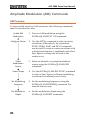
Amplitude Modulation (AM) Commands ......................... 112
AM Overview ................................................................... 112
Frequency Modulation (FM) Commands .......................... 116
FM Overview ................................................................... 116
Frequency-Shift Keying (FSK) Commands ........................ 121
FSK Overview .................................................................. 121
Frequency Sweep Commands........................................... 125
Sweep Overview .............................................................. 125
Arbitrary Waveform Commands ....................................... 130
Arbitrary Waveform Overview .......................................... 130
Save and Recall Commands ............................................. 133
APPENDIX ................................................... 135
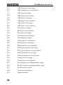
Error Messages ............................................................... 135
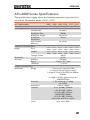
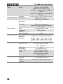
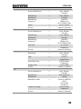
AFG-2000 Series Specifications ....................................... 137
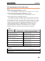
EC Declaration of Conformity .......................................... 141
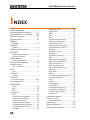
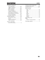
INDEX ......................................................... 142
2
SAFETY INSTRUCTIONS
SAFETY INSTRUCTIONS
This chapter contains important safety instructions
that should be followed when operating and
storing the function generator. Read the following
before any operation to ensure your safety and to
keep the function generator in the best condition.
Safety Symbols
These safety symbols may appear in this manual or on the
instrument.
WARNING
Warning: Identifies conditions or practices that
could result in injury or loss of life.
CAUTION
Caution: Identifies conditions or practices that
could result in damage to the function generator or
to other objects or property.
DANGER High Voltage
Attention: Refer to the Manual
Protective Conductor Terminal
Earth (Ground) Terminal
DANGER Hot Surface
3
AFG-2000 Series User Manual
Double Insulated
Do not dispose electronic equipment as unsorted
municipal waste. Please use a separate collection
facility or contact the supplier from which this
instrument was purchased.
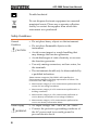
Safety Guidelines
General
Guideline
CAUTION
Do not place heavy objects on the instrument.
Do not place flammable objects on the
instrument.
Avoid severe impact or rough handling that
may damage the function generator.
Avoid discharges of static electricity on or near
the function generator.
Use only mating connectors, not bare wires, for
the terminals.
The instrument should only be disassembled by
a qualified technician.
(Measurement categories) EN 61010-1:2010 specifies the
measurement categories and their requirements as follows. The
instrument falls under category II.
Measurement category IV is for measurement performed at the
source of a low-voltage installation.
Measurement category III is for measurement performed in a
building installation.
Measurement category II is for measurement performed on
circuits directly connected to a low voltage installation.
Measurement category I is for measurements performed on
circuits not directly connected to Mains.
Power Supply
WARNING
4
AC Input voltage: 100 ~ 240V AC, 50 ~ 60Hz.
Connect the protective grounding conductor of
the AC power cord to an earth ground to
prevent electric shock.
SAFETY INSTRUCTIONS
Fuse
WARNING
Cleaning the
function
generator
Operation
Environment
Fuse type: F1A/250V.
Only qualified technicians should replace the
fuse.
To ensure fire protection, replace the fuse only
with the specified type and rating.
Disconnect the power cord and all test leads
before replacing the fuse.
Make sure the cause of fuse blowout is fixed
before replacing the fuse.
Disconnect the power cord before cleaning the
function generator.
Use a soft cloth dampened in a solution of mild
detergent and water. Do not spray any liquid
into the function generator.
Do not use chemicals containing harsh products
such as benzene, toluene, xylene, and acetone.
Location: Indoor, no direct sunlight, dust free,
almost non-conductive pollution (Note below)
and avoid strong magnetic fields.
Relative Humidity: < 80%
Altitude: < 2000m
Temperature: 0°C to 40°C
(Pollution Degree) EN 61010-1:2010 specifies pollution degrees and
their requirements as follows. The function generator falls under
degree 2.
Pollution refers to “addition of foreign matter, solid, liquid, or
gaseous (ionized gases), that may produce a reduction of dielectric
strength or surface resistivity”.
Pollution degree 1: No pollution or only dry, non-conductive
pollution occurs. The pollution has no influence.
Pollution degree 2: Normally only non-conductive pollution
occurs. Occasionally, however, a temporary conductivity caused
by condensation must be expected.
Pollution degree 3: Conductive pollution occurs, or dry, nonconductive pollution occurs which becomes conductive due to
condensation which is expected. In such conditions, equipment
is normally protected against exposure to direct sunlight,
5
AFG-2000 Series User Manual
precipitation, and full wind pressure, but neither temperature
nor humidity is controlled.
Storage
environment
Disposal
6
Location: Indoor
Relative Humidity: < 70%
Temperature: -10°C to 70°C
Do not dispose this instrument as unsorted
municipal waste. Please use a separate collection
facility or contact the supplier from which this
instrument was purchased. Please make sure
discarded electrical waste is properly recycled to
reduce environmental impact.
SAFETY INSTRUCTIONS
Power cord for the United Kingdom
When using the function generator in the United Kingdom, make sure the
power cord meets the following safety instructions.
NOTE: This lead/appliance must only be wired by competent persons
WARNING: THIS APPLIANCE MUST BE EARTHED
IMPORTANT: The wires in this lead are coloured in accordance with the
following code:
Green/ Yellow:
Earth
Blue:
Neutral
Brown:
Live (Phase)
As the colours of the wires in main leads may not correspond with the
coloured marking identified in your plug/appliance, proceed as follows:
The wire which is coloured Green & Yellow must be connected to the Earth
terminal marked with either the letter E, the earth symbol
or coloured
Green/Green & Yellow.
The wire which is coloured Blue must be connected to the terminal which is
marked with the letter N or coloured Blue or Black.
The wire which is coloured Brown must be connected to the terminal
marked with the letter L or P or coloured Brown or Red.
If in doubt, consult the instructions provided with the equipment or contact
the supplier.
This cable/appliance should be protected by a suitably rated and approved
HBC mains fuse: refer to the rating information on the equipment and/or
user instructions for details. As a guide, a cable of 0.75mm2 should be
protected by a 3A or 5A fuse. Larger conductors would normally require
13A types, depending on the connection method used.
Any exposed wiring from a cable, plug or connection that is engaged in a
live socket is extremely hazardous. If a cable or plug is deemed hazardous,
turn off the mains power and remove the cable, any fuses and fuse
assemblies. All hazardous wiring must be immediately destroyed and
replaced in accordance to the above standard.
7
AFG-2000 Series User Manual
GETTING STARTED
The Getting started chapter introduces the
function generator’s main features, appearance
and introduces a quick instructional summary of
some of the basic functions. For comprehensive
operation instructions, please see the operation
chapter.
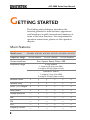
Main Features
Model name
AFG-2005 AFG-2105 AFG-2012 AFG-2112 AFG-2025 AFG-2125
Frequency Range
0.1Hz~5MHz
0.1Hz~12MHz
0.1Hz~25MHz
Output waveform
Sine, Square, Ramp, Noise, ARB
Amplitude range
0.1Hz~20MHz
1 mVpp to 10 Vpp (into 50Ω)
2 mVpp to 20 Vpp (open-circuit)
20MHzHz~25MHz
1 mVpp to 5 Vpp (into 50Ω)
2 mVpp to 10 Vpp (open-circuit)
Variable Offset
Variable Duty
SYNC (TTL) output
ouput
Save/Recall
Sweep operation
—
—
—
AM
—
—
—
FM
—
—
—
FSK
—
—
—
Frequency Counter
—
—
—
8
GETTING STARTED
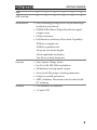
ARB
USB Interface
Performance
DDS technology using an FPGA provides high
resolution waveforms
25MHz DDS (Direct Digital Synthesis) signal
output series
0.1Hz resolution
Full Function Arbitrary Waveform Capability
20 MSa/s sample rate
10 MHz repetition rate
4 k-point waveform length
10-bit amplitude resolution
Ten 4k waveform memories
Features
Interface
Sine, Square, Ramp, Noise
Int/Ext AM, FM, FSK modulation
Modulation/sweep signal output
Save/recall 10 groups of setting memories
Output overload protection
ARB (Arbitrary Waveform) can be edited with
PC software
USB interface as standard
3.5 inch LCD
9
AFG-2000 Series User Manual
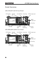
Panel Overview
AFG-2105/2112/2125 Front Panel
LCD Display
Number
pad
Scroll Wheel Arrow keys
SYNC output port
OUTPUT
AFG-2125 Arbitrary Function Generator
SYNC
FUNC
7
8
9
4
5
6
1
2
3
FREQ
50W
AMPL
MAIN
OFST
Enter
Function keys
DUTY
Point
Value
50W
/
0
Save/Recall
POWER
INT/EXT
Hop
Hz/Vpp
kHz/Vrms
MHz/dBm
%
Shape
DEP/DEV
Rate
Start/Stop
Gate
AM
FM
FSK
LIN/LOG
Sweep
Count
Shift
Enter key
ARB
ARB keys
MAIN
output port
OUTPUT
Operation
keys
Output
control key
Power
button
AFG-2005/2012/2025 Front Panel
LCD Display
Number
pad
Scroll Wheel Arrow keys
SYNC output port
OUTPUT
AFG-2025 Arbitrary Function Generator
SYNC
FUNC
7
8
9
4
5
6
1
2
3
FREQ
50W
AMPL
MAIN
OFST
Enter
Function keys
DUTY
Point
50W
/
0
OUTPUT
POWER
Save/Recall
Hz/Vpp
kHz/Vrms
MHz/dBm
%
Shift
Enter key
Value
ARB
ARB keys
10
MAIN
output port
Operation
keys
Output
control key
Power
button
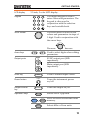
GETTING STARTED
LCD display
Keypad
3.5 inch, 3 color LCD display.
7
8
9
4
5
6
1
2
3
The digital keypad is used to
enter values and parameters. The
keypad is often used in
conjunction with the selection
keys and variable knob.
/
0
The scroll wheel is used to edit
values and parameters in steps of
1 digit. Used in conjunction with
the arrow keys.
Scroll Wheel
Decrease
Increase
Used to select digits when editing
parameters.
Arrow keys
Output ports
SYNC output port (50Ω
impedance).
OUTPUT
SYNC
50W
MAIN
Main output port (50Ω
impedance).
50W
Enter key
Power button
Output control
key
Used to confirm input values.
Enter
Turns the instrument power
on/off.
POWER
OUTPUT
Turns the output on/off.
Hz/Vpp
Selects Hz or Vpp units.
Operation keys
Save/Recall
Shift
+
Hz/Vpp
kHz/Vrms
Saves or recalls waveforms from
memory.
Selects kHz or Vrms units.
11
AFG-2000 Series User Manual
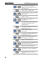
INT/EXT
Shift
+
kHz/Vrms
Selects MHz or dBm units.
MHz/dBm
Hop
Shift
+
MHz/dBm
LIN/LOG
%
+
The AM key is used to turn AM
modulation on/off*.
AM
Shape
AM
+
DEP/DEV
FM
+
Rate
FSK
+
Start/Stop
+
Count
12
Sets the AM, FM, FSK modulation
and sweep function rate*
Selects the Sweep function*.
Sweep
Shift
Selects the modulation depth or
the frequency deviation*.
Selects FSK modulation*.
FSK
Shift
Selects the modulation
waveform*.
The FM key is used to turn FM
modulation on/off*.
FM
Shift
Sets the sweep to linear or
logarithmic*.
The shift key is used to select the
secondary functions on the
operation keys.
Shift
Shift
Sets the ―Hop‖ frequency for FSK
modulation*.
Selects % units.
%
Shift
Sets the source to internal or
external for the modulation and
FSK functions*.
Sets the Start or Stop frequency*.
Sweep
Turns the frequency counter
on/off*.
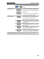
GETTING STARTED
Gate
Shift
ARB edit keys
+
Point
Value
ARB
Function keys
FUNC
Count
Sets the frequency counter gate
time*.
Arbitrary waveform editing keys.
The Point key sets the ARB point
numbers.
The Value key sets the amplitude
value of the selected point.
The FUNC key is used to select
the output waveform type:
Sine, Square, Ramp, Noise, ARB.
FREQ
AMPL
OFST
DUTY
Sets the frequency of the selected
waveform.
Sets the amplitude of the selected
waveform.
The OFST sets the DC offset for
the selected waveform.
The DUTY key sets the duty cycle
of square and ramp waveforms.
*indicates functions/features for the AFG-2105/2112/2125 only.
13
AFG-2000 Series User Manual
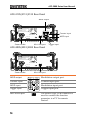
AFG-2105/2112/2125 Rear Panel
MOD output
WARNING
TO AVOID ELECTRIC SHOCK THE POWER CORD PROTECTIVE
GROUNDING CONDUCTOR MUST BE CONNECTED TO GROUND.
NO OPERATOR SERVICEABLE COMPONENTS INSIDE.
DO NOT REMOVE COVERS. REFER SERVICING TO
QUALIFIED PERSONNEL.
OUTPUT
INPUT
MOD
Counter
Counter input
AC 100-240V
50-60Hz 25VA
SER.NO. LABEL
Power socket
Trigger
Mini USB port
MOD input
MOD
Trigger input
AFG-2005/2012/2025 Rear Panel
WARNING
TO AVOID ELECTRIC SHOCK THE POWER CORD PROTECTIVE
GROUNDING CONDUCTOR MUST BE CONNECTED TO GROUND.
NO OPERATOR SERVICEABLE COMPONENTS INSIDE.
DO NOT REMOVE COVERS. REFER SERVICING TO
QUALIFIED PERSONNEL.
AC 100-240V
50-60Hz 25VA
SER.NO. LABEL
Power socket
MOD output
Mini USB port
OUTPUT
INPUT
MOD
Counter
Modulation output port.
Counter input
Counter input port.
MOD input
Modulation input port.
Trigger input
Mini USB B port
14
Trigger
MOD
Trigger input port.
The Mini-B type USB connector is
used to connect the function
generator to a PC for remote
control.
GETTING STARTED
Power input: 100~240V AC
Power Socket
Input
50~60Hz.
AC 100-240V
50-60Hz 25VA
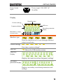
Display
Counter settings
Waveform type
USB icon
Frequency display
Secondary parameter
display
Modulation, sweep,
counter menu
Waveform type
Press the function key to cycle through different
output waveforms.
Counter settings
Gate time counter settings*.
USB icon
Shows the USB interface status.
Frequency
Display
Displays the main waveform frequency settings.
Secondary
parameter display
Displays secondary waveform parameters and
settings.
15
AFG-2000 Series User Manual
Modulation,
sweep, counter
menu
Displays the modulation, sweep and counter
functions as well as the modulating waveform and
source*.
*indicates functions/features for the AFG-2105/2112/2125 only.
16
GETTING STARTED
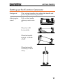
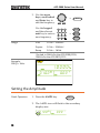
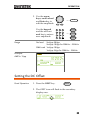
Setting up the Function Generator
Background
This section describes how adjust the handle and
power up the function generator.
Adjusting the
stand
Pull out the handle
sideways and rotate
it.
OUTPUT
AFG-2125 Arbitrary Function Generator
SYNC
FUNC
7
8
9
4
5
6
1
2
3
FREQ
50W
AMPL
MAIN
OFST
Enter
DUTY
Point
Value
50W
/
0
OUTPUT
Save/Recall
POWER
INT/EXT
Hop
LIN/LOG
Hz/Vpp
kHz/Vrms
MHz/dBm
%
Shape
DEP/DEV
Rate
Start/Stop
Gate
AM
FM
FSK
Sweep
Count
Shift
ARB
Place the AFG
horizontally.
Place the handle
upright to tilt the
stand.
Place the handle
vertically to hand
carry.
17
AFG-2000 Series User Manual
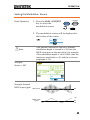
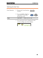
Power Up
1. Connect the power cord to
the socket on the rear
panel.
2. Press the power button on
the front panel.
POWER
3. The instrument will turn on and load the
default settings (see page 33 for default
settings).
The function generator is now ready to be used.
18
QUICK REFERENCE
QUICK REFERENCE
This chapter lists operation shortcuts and default factory settings.
Use this chapter as a handy reference for instrument functions. This
chapter is to be used as a quick reference; for detailed explanations
on parameters, settings and limitations, please see the operation
chapter (page 35) or specifications (page 137).
How to use the Digital Inputs ........................................... 20
Selecting a Waveform ........................................................ 22
Sine Wave ............................................................................. 22
Square Wave ......................................................................... 22
Ramp Wave .......................................................................... 23
ARB ................................................................................... 24
ARB - Points.......................................................................... 24
Modulation ........................................................................ 25
AM (2100 series only) .......................................................... 25
FM (2100 series only) .......................................................... 26
FSK Modulation (2100 series only) ..................................... 27
Sweep (2100 series only) ................................................... 29
Counter (2100 series only) ................................................ 31
Save/Recall ........................................................................ 32
Save ...................................................................................... 32
Recall .................................................................................... 32
Default Settings ................................................................ 33
19
QUICK REFERENCE
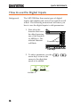
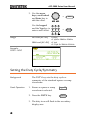
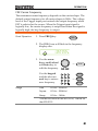
How to use the Digital Inputs
Background
The AFG-2000 has three main types of digital
inputs: the number pad, arrow keys and the scroll
wheel. The following instructions will show you
how to use the digital inputs to edit parameters.
1. First select the
function that must
be edited pressing
one of the function
or ARB keys. The
selected function
will flash.
O
AFG-2025 Arbitrary Function Generator
FUNC
9
4
5
6
1
2
3
OFST
Enter
DUTY
Function keys
Point
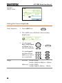
2. To edit a parameter, use the
arrow keys to move the
cursor to the digit that
needs to be edited.
/
0
OUTPUT
Save/Recall
Hz/Vpp
Value
ARB keys
20
8
AMPL
ARB
cursor
7
FREQ
kHz/Vrms
MHz/dBm
%
Shift
QUICK REFERENCE
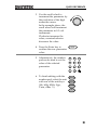
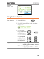
3. Use the scroll wheel to
increment the parameter by
the resolution of the digit
under the cursor.
In the example above, the
scroll wheel will increment
the parameter in 0.1 volt
increments.
Clockwise increases the
value, counterclockwise
decreases the value.
4. Press the Enter key to
confirm the new parameter
value.
5. Alternatively, the number
pad can be used to set the
value of the selected
parameter.
Enter
7
8
9
4
5
6
1
2
3
0
6. To finish editing with the
number pad, select the unit
with one of the unit keys.
(Hz, kHz, MHz, Vpp,
Vrms, dBm, %)
/
Hz/Vpp
kHz/Vrms
MHz/dBm
%
21
AFG-2000 Series User Manual
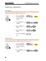
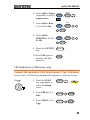
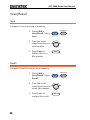
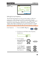
Selecting a Waveform
Sine Wave
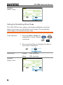
Example: Sine Wave, 10kHz, 1Vpp, 2Vdc
Output
MAIN
50W
1. Press the FUNC
key repeatedly to
select the Sine
wave.
FUNC
→
2. Press FREQ > 1 > 0
> kHz.
FREQ
1
0
3. Press AMPL > 1 >
Vpp.
AMPL
1
Hz/Vpp
4. Press OFST > 2 >
Vpp.
OFST
2
Hz/Vpp
5. Press the OUTPUT
key.
kHz/Vrms
OUTPUT
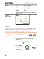
Square Wave
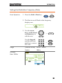
Example: Square Wave, 10kHz, 3Vpp, 75% duty cycle
Output
MAIN
50W
1. Press the FUNC
key repeatedly to
select the Square
wave.
2. Press FREQ > 1 > 0
> kHz.
22
FUNC
FREQ
→
1
0
kHz/Vrms
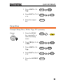
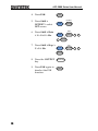
QUICK REFERENCE
3. Press AMPL > 3 >
Vpp.
AMPL
3
Hz/Vpp
4. Press DUTY > 7 > 5
> %.
DUTY
7
5
5. Press the output
key.
%
OUTPUT
Ramp Wave
Example: Ramp Wave, 10kHz, 3Vpp, 25% symmetry
Output
MAIN
50W
1. Press the FUNC
key repeatedly to
select the Ramp
wave.
FUNC
→
2. Press FREQ > 1 > 0
> kHz.
FREQ
1
0
3. Press AMPL > 3 >
Vpp.
AMPL
3
Hz/Vpp
4. Press DUTY > 2 > 5
> %.
DUTY
2
5
5. Press the OUTPUT
key.
kHz/Vrms
%
OUTPUT
23
AFG-2000 Series User Manual
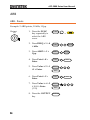
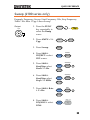
ARB
ARB - Points
Example: 2 ARB points, 10 kHz, 1Vpp.
Output
MAIN
50W
1. Press the FUNC
key repeatedly to
select the ARB
wave.
→
2. Press FREQ > 1 > 0
> kHz.
FREQ
1
0
3. Press AMPL > 1 >
Vpp.
AMPL
1
Hz/Vpp
4. Press Point > 0 >
Enter.
Point
0
5. Press Value > 5 > 1
>1 > Enter.
Value
5
6. Press Point > 1 >
Enter.
Point
1
Value
/
7. Press Value > ± > 5
> 1 >1 > Enter.
(-511)
8. Press the OUTPUT
key.
24
FUNC
kHz/Vrms
Enter
1
1
Enter
Enter
OUTPUT
Enter
5
1
1
QUICK REFERENCE
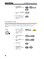
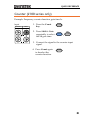
Modulation
AM (2100 series only)
Example: AM modulation. 100Hz modulating square wave. 1 Vpp,
1kHz Sine wave carrier. 70% modulation depth. Internal source
signal.
Output
MAIN
50W
1. Press the FUNC
key repeatedly to
select the Sine
wave.
FUNC
→
2. Press FREQ > 1 >
kHz.
FREQ
1
3. Press AMPL > 1 >
Vpp.
AMPL
1
4. Press AM.
AM
5. Press Shift >
INT/EXT > select
INT source.
Shift
6. Press Shift > Shape
repeatedly to select
the Square wave.
Shift
kHz/Vrms
Hz/Vpp
INT/EXT
+
kHz/Vrms
Shape
7. Press Shift > Rate
> 1 > 0 > 0 > Hz.
+
AM
→
Rate
Shift
0
+
FSK
1
0
Hz/Vpp
25
AFG-2000 Series User Manual
8. Press Shift >
DEP/DEV> 7 > 0 >
%.
9. Press the OUTPUT
key.
10. Press AM again to
deselect the AM
function.
DEP/DEV
Shift
FM
+
7
0
%
OUTPUT
AM
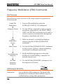
FM (2100 series only)
Example: FM modulation. 100Hz modulating square wave. 1Vpp,
1kHz Sine wave carrier. 100 Hz frequency deviation. Internal
Source.
Output
MAIN
50W
26
1. Press the FUNC
key repeatedly to
select the Sine
wave.
FUNC
→
2. Press FREQ > 1 >
kHz.
FREQ
1
3. Press AMPL > 1 >
Vpp.
AMPL
1
4. Press FM.
FM
5. Press Shift >
INT/EXT > select
INT source.
Shift
kHz/Vrms
Hz/Vpp
INT/EXT
+
kHz/Vrms
QUICK REFERENCE
6. Press Shift > Shape
repeatedly to select
Square wave.
Shape
Shift
7. Press Shift > Rate
> 1 > 0 > 0 > Hz.
8. Press Shift >
DEP/DEV> 1 > 0 >
0> Hz
FSK
+
1
0
1
0
Hz/Vpp
DEP/DEV
Shift
FM
+
Hz/Vpp
0
10. Press FM again to
deselect the AM
function.
→
Rate
Shift
0
9. Press the OUTPUT
key.
AM
+
OUTPUT
FM
FSK Modulation (2100 series only)
Example: FSK modulation. 10Hz Hop frequency. 1Vpp, 1kHz Ramp
carrier wave. 100 Hz Rate (modulation frequency). Internal Source.
Output
MAIN
50W
1. Press the FUNC
key repeatedly to
select the Ramp
wave.
2. Press FREQ > 1 >
kHz.
3. Press AMPL > 1 >
Vpp.
FUNC
→
FREQ
1
AMPL
1
kHz/Vrms
Hz/Vpp
27
AFG-2000 Series User Manual
4. Press FSK.
FSK
5. Press Shift >
INT/EXT > select
INT source.
Shift
INT/EXT
6. Press Shift > Rate
> 1 > 0 > 0 > Hz.
Rate
Shift
+
9. Press FSK again to
deselect the FSK
function.
28
1
0
1
0
Hop
Shift
+
Hz/Vpp
8. Press the OUTPUT
key.
FSK
Hz/Vpp
0
7. Press Shift > Hop >
1 > 0 > Hz.
+
kHz/Vrms
OUTPUT
FSK
MHz/dBm
QUICK REFERENCE
Sweep (2100 series only)
Example: Frequency Sweep. Start Frequency 1Hz, Stop Frequency
1MHz. 1Hz Rate. 1Vpp. Linear Sweep.
Output
MAIN
50W
1. Press the FUNC
key repeatedly to
select the Ramp
wave.
FUNC
2. Press AMPL > 1 >
Vpp.
AMPL
3. Press Sweep.
Sweep
4. Press Shift >
INT/EXT > select
INT source.
Shift
5. Press Shift >
Start/Stop select
Start> 1 > Hz.
Shift
6. Press Shift >
Start/Stop select
Stop> 1 > MHz.
7. Press Shift > Rate
> 1 > Hz.
→
1
Hz/Vpp
INT/EXT
+
kHz/Vrms
Start/Stop
+
Sweep
1
Hz/Vpp
Start/Stop
Shift
+
Sweep
1
MHz/dBm
Rate
Shift
+
FSK
1
Hz/Vpp
8. Press Shift >
LIN/LOG > select
LINS.
INT/EXT
Shift
+
kHz/Vrms
29
AFG-2000 Series User Manual
9. Press the OUTPUT
key.
10. Press Sweep again
to deselect the
sweep function.
30
OUTPUT
Sweep
QUICK REFERENCE
Counter (2100 series only)
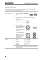
Example: Frequency counter function, gate time 1s.
Input
OUTPUT
INPUT
MOD
Counter
1. Press the Count
key.
2. Press Shift > Gate
repeatedly to select
the 1S gate time.
FSK
MOD
Count
Gate
Shift
+
Count
3. Connect the signal to the counter input
signal.
4. Press Count again
to deselect the
counter function.
Count
31
AFG-2000 Series User Manual
Save/Recall
Save
Example: Save waveform to memory.
1. Press Shift >
Save/Recall. Select
Save.
Save/Recall
Shift
+
Hz/Vpp
2. Turn the scroll
wheel and choose a
save number.
3. Press Enter to
confirm the save
file number.
Enter
Recall
Example: Recall waveform from memory.
1. Press Shift >
Save/Recall. Select
Recall.
Save/Recall
Shift
2. Turn the scroll
wheel and choose a
saved file number.
3. Press Enter to
confirm the recall.
32
Enter
+
Hz/Vpp
QUICK REFERENCE
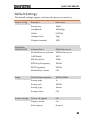
Default Settings
The default settings appear each time the power is turned on.
Output Config.
Modulation
(AM/FM/FSK)
Sweep
System settings
Function
Sine wave
Frequency
1kHz
Amplitude
100mVpp
Offset
0.00Vdc
Output units
Vpp
Output terminal
50Ω
Carrier Wave
1kHz Sine wave
Modulation waveforms
100Hz Sine wave
AM Depth
100%
FM Deviation
10Hz
FSK Hop Frequency
100Hz
FSK Frequency
500Hz
Modulation Status
Off
Start/Stop frequency
100Hz/1kHz
Sweep time
1s
Sweep rate
100Hz
Sweep type
Linear
Sweep status
Off
Power off signal
On
Display mode
On
Error queue
cleared
33
AFG-2000 Series User Manual
Memory settings (ARB)
No change
Output
Off
Interface config.
USB
CDC
Calibration
Calibration Menu
Restricted
34
OPERATION
OPERATION
The Operation chapter shows how to output basic waveforms and
create ARB waveforms. The AFG-2105/ 2112/ 2125 can also perform
advanced functions such as modulation, sweep, FSK and counter
functions.
Select a Waveform ............................................................. 37
Sine, Square, Ramp, Noise Waveform................................. 37
Setting the Frequency ........................................................ 37
Setting the Amplitude........................................................ 38
Setting the DC Offset ........................................................ 39
Setting the Duty Cycle/Symmetry ...................................... 40
Amplitude Modulation (AM) (AFG-2100 Series) ............... 42
Selecting AM Modulation .................................................... 43
AM Carrier Waveform .......................................................... 43
Setting the Carrier Frequency............................................... 44
Setting the Carrier Amplitude .............................................. 45
Setting the Modulating Wave Shape ................................... 46
Setting the Modulation Frequency (Rate) ........................... 46
Modulation Depth ................................................................ 47
Setting the Modulation Source ............................................ 49
Frequency Modulation (FM) (AFG-2100 Series) ................. 50
Selecting FM Modulation..................................................... 51
FM Carrier Waveform ........................................................... 51
Setting the Carrier Frequency............................................... 52
Setting the Carrier Amplitude .............................................. 53
Setting the Modulating Wave Shape ................................... 54
Setting the Modulation Frequency (Rate) ........................... 55
Frequency Deviation............................................................. 56
Setting the Modulation Source ............................................ 57
Frequency Shift Keying (FSK) Modulation (AFG-2100 Series)
.......................................................................................... 59
Selecting FSK Modulation .................................................... 60
FSK Carrier Waveform .......................................................... 60
FSK Carrier Frequency .......................................................... 61
35
AFG-2000 Series User Manual
Setting the Carrier Amplitude .............................................. 62
Setting the Hop Frequency .................................................. 63
FSK Rate ............................................................................... 64
Setting the FSK Source ........................................................ 65
Frequency Sweep (AFG-2100 Series) .................................. 67
Selecting Sweep ................................................................... 68
Setting Start and Stop Frequency ........................................ 68
Sweep Mode......................................................................... 70
Sweep Rate ........................................................................... 71
Setting the Sweep Source (Trigger) ..................................... 72
Creating an Arbitrary Waveform ......................................... 74
Using the Frequency Counter ............................................. 76
Selecting the Frequency Counter Function ......................... 76
Selecting the Gate Time ....................................................... 77
Using the SYNC Output Port ............................................. 78
Connecting the SYNC Output Port ..................................... 78
SYNC Output Signal ............................................................ 78
Save and Recall State/ARB Waveform ................................ 82
36
OPERATION
Select a Waveform
The AFG-2000 can output four standard waveforms: sine, square,
ramp and noise waveforms.
Sine, Square, Ramp, Noise Waveform
Panel Operation
1. Press the FUNC key
repeatedly to select a
standard waveform (Sine,
Square, Ramp, Noise).
FUNC
→
Example:
Sine wave
Note
The modulation, FSK, sweep and counter functions
must be disabled before a standard waveform can be
output.
Setting the Frequency
Panel Operation
1. Press the FREQ key.
FREQ
2. The FREQ icon will flash in the frequency
display area.
37
AFG-2000 Series User Manual
3. Use the arrow
keys, scroll wheel
and Enter key to
edit the frequency.
Use the keypad
and the relevant
unit key to enter a
new frequency.
Range
→
7
8
9
4
5
6
1
2
3
0
Sine
0.1Hz ~ 25MHz*
Square
0.1Hz ~ 25MHz*
Ramp
0.1Hz ~ 1MHz
Enter
Hz/Vpp
→
kHz/Vrms
MHz/dBm
/
*limited to 5MHz for the AFG-2005/2105,
12MHz for the AFG-2012/2112.
Example:
FREQ = 1kHz
Setting the Amplitude
Panel Operation
1. Press the AMPL key.
AMPL
2. The AMPL icon will flash in the secondary
display area.
38
OPERATION
3. Use the arrow
keys, scroll wheel
and Enter key to
edit the amplitude.
Use the keypad
and the relevant
unit key to enter a
new amplitude.
Range
No load
→
7
8
9
4
5
6
1
2
3
0
Enter
Hz/Vpp
→
kHz/Vrms
MHz/dBm
/
2mVpp~20Vpp
2mVpp~10Vpp for 20MHz – 25MHz
50Ω Load 1mVpp~10Vpp
1mVpp~5Vpp for 20MHz – 25MHz
Example:
AMPL= 1Vpp
Setting the DC Offset
Panel Operation
1. Press the OFST key.
OFST
2. The OFST icon will flash in the secondary
display area.
39
AFG-2000 Series User Manual
3. Use the arrow
keys, scroll wheel
and Enter key to
edit the offset.
→
Use the keypad
and the Vpp key to
enter a new offset.
7
8
9
4
5
6
1
2
3
0
Range
No Load (AC+DC)
→
Enter
Hz/Vpp
/
±10Vpk
±5 Vpk for 20MHz–25MHz
50Ω Load (AC+DC) ±5 Vpk
±2.5 Vpk for 20MHz–25MHz
Example:
OFST= 1VDC
Setting the Duty Cycle/Symmetry
Background
Panel Operation
The DUTY key sets the duty cycle or
symmetry of the standard square or ramp
waveforms.
1. Ensure a square or ramp
waveform is selected.
2. Press the DUTY key.
Page 37
DUTY
3. The duty icon will flash in the secondary
display area.
40
OPERATION
4. Use the arrow
keys, scroll wheel
and Enter key to
edit the duty
cycle/symmetry.
Use the keypad
and the % key to
enter a new duty
cycle/symmetry.
Duty Cycle Range
8
9
4
5
6
1
2
3
0
1.0% ~ 99.9%
≤ 5MHz
20.0% ~ 80.0%
≤ 10MHz
40.0 ~ 60.0%
≤ 25MHz
50.0% (fixed)
All frequencies
0%
Enter
→
%
/
≤ 100kHz
10%
Symmetry Range
7
→
50%
90%
0% ~ 100%
50%
100%
Example:
DUTY= 50.0%
41
AFG-2000 Series User Manual
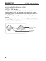
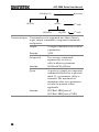
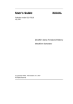
Amplitude Modulation (AM)
(AFG-2100 Series)
An AM waveform is produced from a carrier waveform and a
modulating waveform. The amplitude of the modulated carrier
waveform depends on the amplitude of the modulating waveform.
The AFG-2100 function generator can set the carrier frequency,
amplitude and offset as well as internal or external modulation
sources.
AM modulation is only applicable for the AFG-2105, AFG-2112 and
the AFG-2125 function generators.
Modulated Carrier
Waveform
Modulating
waveform
42
OPERATION
Selecting AM Modulation
Panel Operation
1. Press the AM key.
AM
2. The modulation, sweep and counter menu
display will appear. The AM icon indicates
that the AM function is active.
Example:
AM activated
Note
AM modulation can be deactivated by pressing the
AM key again.
AM Carrier Waveform
Background
Selecting the
Carrier Shape
The FUNC key selects the AM carrier waveform.
Sine, square or ramp waveforms can be used as the
carrier. The default waveform is set to sine. Noise
is not available as a carrier shape. Before the
carrier shape can be selected, ensure AM is active,
page 43.
1. Press the FUNC key
repeatedly to select a
carrier waveform (Sine,
Square, Ramp).
FUNC
→
43
AFG-2000 Series User Manual
Range
AM Carrier Shape
sine, square, ramp
Setting the Carrier Frequency
Panel Operation
1. Press FREQ key.
FREQ
2. The FREQ icon will flash in the frequency
display area.
3. Use the arrow
keys, scroll wheel
and Enter key to
edit the frequency.
Use the keypad
and the relevant
unit key to enter a
new frequency.
Range
→
7
8
9
4
5
6
1
2
3
0
Sine
0.1Hz ~ 25MHz*
Square
0.1Hz ~ 25MHz*
Ramp
0.1Hz ~ 1MHz
/
Enter
Hz/Vpp
→
kHz/Vrms
MHz/dBm
*limited to 5MHz for the AFG-2105, 12MHz for
the AFG-2112.
Example:
FREQ = 1kHz
44
OPERATION
Setting the Carrier Amplitude
Panel Operation
1. Press AMPL key.
AMPL
2. The AMPL icon will flash in the secondary
display area.
3. Use the arrow
keys, scroll wheel
and Enter key to
edit the amplitude.
Use the keypad
and the relevant
unit key to enter a
new amplitude.
Range
No Load
→
7
8
9
4
5
6
1
2
3
0
/
Enter
Hz/Vpp
→
kHz/Vrms
MHz/dBm
2mVpp~20Vpp
2mVpp~10Vpp for 20MHz – 25MHz
50Ω Load 1mVpp~10Vpp
1mVpp~5Vpp for 20MHz – 25MHz
Example:
AMPL= 1Vpp
45
AFG-2000 Series User Manual
Setting the Modulating Wave Shape
The AFG-2100 has sine, square and ramp modulating waveform
shapes. Sine waves are the default wave shape.
Panel Operation
1. Press the Shift + Shape key
repeatedly to select a shape
waveform.
Shape
Shift
+
AM
→
2. The waveform Shape is displayed in blue at
the bottom of the panel.
Restrictions
Square
50% duty cycle
Ramp
50% symmetry
Example:
Shape = Sine
Setting the Modulation Frequency (Rate)
Panel Operation
1. Press the Shift + Rate key.
Rate
Shift
+
FSK
2. The Rate icon will flash in the frequency
display area.
46
OPERATION
3. Use the arrow
keys, scroll wheel
and Enter key to
edit the rate.
Use the keypad
and the relevant
unit key to enter a
new rate.
Range
→
7
8
9
4
5
6
1
2
3
0
Enter
Hz/Vpp
→
kHz/Vrms
/
(Internal source) 2mHz ~ 20kHz
Default
100Hz
Example:
Rate= 100Hz
Modulation Depth
Modulation depth is the ratio (as a percentage) of the unmodulated
carrier amplitude and the minimum amplitude deviation of the
modulated waveform. In other words, modulation depth is the
maximum amplitude of the modulated waveform compared to the
carrier waveform as a percentage.
Panel Operation
1. Press the Shift + DEP/DEV
key.
DEP/DEV
Shift
+
FM
2. The DEP icon will flash in the secondary
display area.
47
AFG-2000 Series User Manual
3. Use the arrow
keys, scroll wheel
and Enter key to
edit the modulation
depth.
Use the keypad
and the % key to
enter a new depth.
7
8
9
4
5
6
1
2
3
0
Range
→
Enter
→
%
/
Depth
0% ~ 120%
Default
100%
Example:
DEP= 100%
Note
When the modulation depth is greater than
100%, the output cannot exceed ±5VPeak
(50Ω load).
If an external modulation source is
selected, modulation depth is limited to
±5V from the MOD input port on the rear
panel. For example, if the modulation depth
is set to 100%, then the maximum
amplitude is +5V, and the minimum
amplitude is -5V.
48
OPERATION
Setting the Modulation Source
Panel Operation
1. Press the Shift + INT/EXT
key to select the
modulation source.
INT/EXT
Shift
+
kHz/Vrms
→
2. The modulation source will be displayed at
the bottom of the screen.
Note
If an external modulation source is selected,
modulation depth is limited to ± 5V from the
MOD input port on the rear panel. For example,
if the modulation depth is set to 100%, then the
maximum amplitude is +5V, and the minimum
amplitude is -5V.
Example:
Source = INT
Example: External
MOD input signal
AM output
MOD input
signal
0V
+5V
0V
-5V
49
AFG-2000 Series User Manual
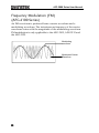
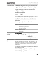
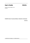
Frequency Modulation (FM)
(AFG-2100 Series)
An FM waveform is produced from a carrier waveform and a
modulating waveform. The instantaneous frequency of the carrier
waveform varies with the magnitude of the modulating waveform.
FM modulation is only applicable to the AFG-2105, AFG-2112 and
the AFG-2125.
Modulating
waveform
Modulated Carrier
Waveform
50
OPERATION
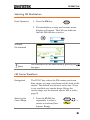
Selecting FM Modulation
Panel Operation
1. Press the FM key.
FM
2. The modulation, sweep and counter menu
display will appear. The FM icon indicates
that the FM function is active.
Example:
FM activated
Note
FM modulation can be deactivated by pressing the FM
key again.
FM Carrier Waveform
Background
Selecting the
Carrier Shape
The FUNC key selects the FM carrier waveform.
Sine, square or ramp waveforms can be used as the
carrier. The default waveform is set to sine. Noise
is not available as a carrier shape. Before the
carrier shape can be selected, ensure FM is active,
page 51.
1. Press the FUNC key
repeatedly to select a
carrier waveform (Sine,
Square, Ramp).
FUNC
→
51
AFG-2000 Series User Manual
Range
FM Carrier Shape
sine, square, ramp
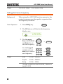
Setting the Carrier Frequency
Background
Panel Operation
When using the AFG-2100 function generator, the
carrier frequency must be equal to or greater than
the frequency deviation.
1. Press FREQ key.
FREQ
2. The FREQ icon will flash in the frequency
display area.
3. Use the arrow
keys, scroll wheel
and Enter key to
edit the frequency.
Use the keypad
and the relevant
unit key to enter a
new frequency.
Range
→
7
8
9
4
5
6
1
2
3
0
Sine
0.1Hz ~ 25MHz*
Square
0.1Hz ~ 25MHz*
Ramp
0.1Hz ~ 1MHz
/
Enter
Hz/Vpp
→
kHz/Vrms
MHz/dBm
*limited to 5MHz for the AFG-2105, 12MHz for
the AFG-2112.
52
OPERATION
Example:
FREQ = 1kHz
Setting the Carrier Amplitude
Panel Operation
1. Press AMPL key.
AMPL
2. The AMPL icon will flash in the secondary
display area.
3. Use the arrow
keys, scroll wheel
and Enter key to
edit the amplitude.
Use the keypad
and the relevant
unit key to enter a
new amplitude.
Range
→
7
8
9
4
5
6
1
2
3
0
/
Enter
Hz/Vpp
→
kHz/Vrms
MHz/dBm
No Load
2mVpp~20Vpp
2mVpp~10Vpp for 20MHz – 25MHz
50Ω load
1mVpp~10Vpp
1mVpp~5Vpp for 20MHz – 25MHz
53
AFG-2000 Series User Manual
Example:
AMPL= 1Vpp
Setting the Modulating Wave Shape
The AFG-2100 has sine, square and ramp modulating waveform
shapes. Sine waves are the default wave shape. The modulating
wave shape is for internal sources only.
Panel Operation
1. Press the Shift + Shape key
repeatedly to select a shape
waveform.
Shape
Shift
+
AM
→
2. The waveform Shape is displayed in blue at
the bottom of the panel.
Restrictions
Example:
Shape = Sine
54
Square
50% duty cycle
Ramp
50% symmetry
OPERATION
Setting the Modulation Frequency (Rate)
Panel Operation
1. Press the Shift + Rate key.
Rate
Shift
+
FSK
2. The Rate icon will flash in the frequency
display area.
3. Use the arrow
keys, scroll wheel
and Enter key to
edit the rate.
Use the keypad
and the relevant
unit key to enter a
new rate.
Range
→
7
8
9
4
5
6
1
2
3
0
Enter
Hz/Vpp
→
kHz/Vrms
/
(Internal source) 2mHz ~ 20kHz
Default
100Hz
Example:
Rate= 100Hz
55
AFG-2000 Series User Manual
Frequency Deviation
The frequency deviation is the peak frequency deviation from the
carrier wave and the modulated wave.
Panel Operation
1. Press the Shift + DEP/DEV
key.
DEP/DEV
Shift
+
FM
2. The DEV icon will flash in the frequency
display area.
3. Use the arrow
keys, scroll wheel
and Enter key to
edit the frequency
deviation.
Use the keypad
and the relevant
unit key to enter a
new frequency
deviation.
Range
→
7
8
9
4
5
6
1
2
3
0
/
Sine
DC ~ 25MHz*
Square
DC ~ 25MHz*
Ramp
DC ~ 1MHz
Default
10Hz
Enter
Hz/Vpp
→
kHz/Vrms
MHz/dBm
*limited to 5MHz for the AFG-2105, 12MHz for
the AFG-2112.
56
OPERATION
Note
The frequency deviation must be equal to or
less than the carrier frequency.
The sum of the carrier frequency and
frequency deviation must be less than or
equal to the maximum carrier.
The maximum frequency deviation allowed
will be limited by the set carrier frequency.
Example:
DEV = 10Hz
Setting the Modulation Source
Panel Operation
1. Press the Shift + INT/EXT
key to select the
modulation source.
INT/EXT
Shift
+
kHz/Vrms
→
2. The modulation source will be displayed at
the bottom of the screen.
Range
Source
INT, EXT
57
AFG-2000 Series User Manual
Connection
(EXT source only)
Note
For external sources,
connect the modulation
source signal to the MOD
input port on the rear
panel.
OUTPUT
INPUT
MOD
Counter
Trigger
MOD
When the source is set to EXT (external) the
carrier waveform is modulated by an external
signal. The frequency deviation is controlled by
the ±5V signal that is input into the MOD input
port. The ±5V input signal directly corresponds
to the set frequency deviation. +5V increases the
frequency by the set deviation frequency and -5V
reduces the frequency to below the carrier
frequency by the amount set by the deviation
frequency. For example: if the deviation
frequency is set to 1kHz, an input voltage of +5V
will increase the frequency to 1kHz, whilst an
input voltage of -5V will reduce the frequency
below that of the carrier by 1kHz.
Example:
Source = INT
Example: External
MOD input signal
FM output
MOD input
signal
58
0V
+5V
0V
-5V
OPERATION
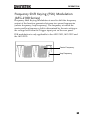
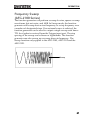
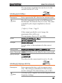
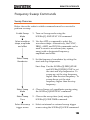
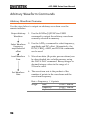
Frequency Shift Keying (FSK) Modulation
(AFG-2100 Series)
Frequency Shift Keying Modulation is used to shift the frequency
output of the function generator between two preset frequencies
(carrier frequency, hop frequency). The frequency at which the
carrier and hop frequency shift is determined by the rate setting or
the voltage level from the Trigger input port on the rear panel.
FSK modulation is only applicable to the AFG-2105, AFG-2112 and
the AFG-2125.
Carrier Frequency
Hop Frequency
59
AFG-2000 Series User Manual
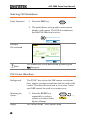
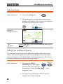
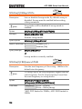
Selecting FSK Modulation
Panel Operation
1. Press the FSK key.
FSK
2. The modulation, sweep and counter menu
display will appear. The FSK icon indicates
that the FSK function is active.
Example:
FSK activated
Note
FSK modulation can be deactivated by pressing the
FSK key again.
FSK Carrier Waveform
Background
Selecting the
Carrier
Range
60
The FUNC key selects the FSK carrier waveform.
Sine, square or ramp waveforms can be used as the
carrier. The default waveform is set to sine. Noise
and ARB cannot be used as a carrier wave.
1. Press the FUNC key
repeatedly to select a
carrier waveform (Sine,
Square, Ramp).
FUNC
FSK Carrier Shape sine, square, ramp
→
OPERATION
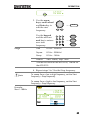
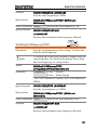
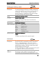
FSK Carrier Frequency
The maximum carrier frequency depends on the carrier shape. The
default carrier frequency for all carrier shapes is 1kHz. The voltage
level of the Trigger input port controls the output frequency when
EXT is selected as the source. When the Trigger input signal is
logically low, the carrier frequency is output and when the signal is
logically high, the hop frequency is output.
Panel Operation
1. Press FREQ key.
FREQ
2. The FREQ icon will flash in the frequency
display area.
3. Use the arrow
keys, scroll wheel
and Enter key to
edit the frequency.
Use the keypad
and the relevant
unit key to enter a
new frequency.
Range
→
7
8
9
4
5
6
1
2
3
0
Sine
0.1Hz ~ 25MHz*
Square
0.1Hz ~ 25MHz*
Ramp
0.1Hz ~ 1MHz
/
Enter
Hz/Vpp
→
kHz/Vrms
MHz/dBm
*limited to 5MHz for the AFG-2105, 12MHz for
the AFG-2112.
61
AFG-2000 Series User Manual
Example:
FREQ = 1kHz
Setting the Carrier Amplitude
Panel Operation
1. Press AMPL key.
AMPL
2. The AMPL icon will flash in the secondary
display area.
3. Use the arrow
keys, scroll wheel
and Enter key to
edit the amplitude.
Use the keypad
and the relevant
unit key to enter a
new amplitude.
Range
No Load
→
7
8
9
4
5
6
1
2
3
0
/
Enter
Hz/Vpp
→
kHz/Vrms
MHz/dBm
2mVpp~20Vpp
2mVpp~10Vpp for 20MHz – 25MHz
50Ω Load 1mVpp~10Vpp
1mVpp~5Vpp for 20MHz – 25MHz
62
OPERATION
Example:
AMPL= 1Vpp
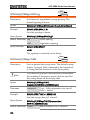
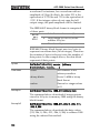
Setting the Hop Frequency
The default Hop frequency for all waveform shapes is 100 Hz. A
square wave with a duty cycle of 50% is used for the internal
modulation waveform. The voltage level of the Trigger input signal
controls the output frequency when EXT is selected. When the
Trigger input signal is logically low the carrier frequency is output
and when the signal is logically high, the hop frequency is output.
Panel Operation
1. Press the Shift + Hop key.
Hop
Shift
+
MHz/dBm
2. The Hop icon will flash in the frequency
display area.
3. Use the arrow
keys, scroll wheel
and Enter key to
edit the hop
frequency.
Use the keypad
and the relevant
unit key to enter a
hop frequency.
→
7
8
9
4
5
6
1
2
3
0
/
Enter
Hz/Vpp
→
kHz/Vrms
MHz/dBm
63
AFG-2000 Series User Manual
Range
Sine
0.1Hz ~ 25MHz*
Square
0.1Hz~ 25MHz*
Ramp
0.1Hz~ 1MHz
Default
100Hz
*limited to 5MHz for the AFG-2105, 12MHz for
the AFG-2112.
Example:
Hop = 100Hz
FSK Rate
FSK Rate function is used to determine the rate at which the output
frequency changes between the carrier and hop frequencies. The
FSK Rate function only applies to internal FSK sources.
Panel Operation
1. Press the Shift + Rate key.
Rate
Shift
+
FSK
2. The Rate icon will flash in the frequency
display area.
3. Use the arrow
keys, scroll wheel
and Enter key to
edit the rate.
64
→
Enter
OPERATION
Use the keypad
and the relevant
unit key to enter a
new rate.
Range
7
8
9
4
5
6
1
2
3
0
Hz/Vpp
→
kHz/Vrms
/
(Internal source) 2mHz ~ 20kHz
Default
100Hz
Example:
Rate= 1KHz
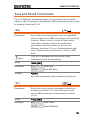
Setting the FSK Source
The AFG-2000 accepts internal and external FSK sources, with
internal as the default source. When the FSK source is set to internal,
the FSK rate is configured using the FSK Rate function. When an
external source is selected the FSK rate is equal to the frequency of
the Trigger input signal on the rear panel. When the input signal is
logically low the carrier frequency is output and when the signal is
logically high, the hop frequency is output.
Panel Operation
1. Press the Shift + INT/EXT
key to select the
modulation source.
INT/EXT
Shift
+
kHz/Vrms
→
2. The FSK source will be displayed at the
bottom of the screen.
Range
Source
INT, EXT
65
AFG-2000 Series User Manual
Connection
(EXT source only)
For external sources,
connect the FSK rate source
signal to the Trigger input
port on the rear panel.
OUTPUT
INPUT
MOD
Counter
Trigger
MOD
Example:
Source = EXT
Example: External
trigger input
signal
FSK output
Trigger input
signal
66
0V
OPERATION
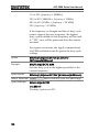
Frequency Sweep
(AFG-2100 Series)
The function generator can perform a sweep for sine, square or ramp
waveforms, but not noise, and ARB. In Sweep mode, the function
generator will sweep from a start frequency to a stop frequency over
a number of designated steps. If an external source is selected, the
function generator can be used to output a single sweep each time a
TTL level pulse is received from the Trigger input port. The step
spacing of the sweep can be linear or logarithmic. The function
generator can also sweep up or sweep down in frequency. The
Sweep function only applies to the AFG-2105, AFG-2112 and the
AFG-2125.
Sweep
67
AFG-2000 Series User Manual
Selecting Sweep
Panel Operation
1. Press the Sweep key.
Sweep
2. The modulation, sweep and counter menu
display will appear. The Sweep icon indicates
that the Sweep function is active.
Example:
Sweep activated
Note
Sweep modulation can be deactivated by pressing the
Sweep key again.
Setting Start and Stop Frequency
The start and stop frequencies define the upper and lower sweep
limits. The function generator will sweep from the start through to
the stop frequency and cycle back to the start frequency. The sweep
is phase continuous over the full sweep range.
Panel Operation
1. Pressing the Shift +
Start/Stop key will toggle
between the start and stop
frequencies. Select the Start
frequency icon.
Start/Stop
Shift
+
Sweep
→ Start
2. The Start icon will flash in the frequency
display area when selected.
68
OPERATION
3. Use the arrow
keys, scroll wheel
and Enter key to
edit the start
frequency.
Use the keypad
and the relevant
unit key to enter a
new start
frequency.
Range
→
7
8
9
4
5
6
1
2
3
0
Enter
Hz/Vpp
→
/
Sine
0.1Hz ~ 25MHz*
Square
0.1Hz ~ 25MHz*
Ramp
0.1Hz ~ 1MHz
Default
Start: 100Hz, Stop: 1kHz
kHz/Vrms
MHz/dBm
*limited to 5MHz for the AFG-2105, 12MHz for
the AFG-2112.
4. Repeat steps 1 to 3 for the Stop frequency.
Note
To sweep from a low to high frequency, set the Start
frequency < Stop frequency.
To sweep from a high to low frequency, set the Start
frequency > Stop frequency.
Example:
Start = 100Hz
69
AFG-2000 Series User Manual
Example:
Stop = 1kHz
Sweep Mode
Sweep mode is used to select between linear or logarithmic
sweeping. Linear sweeping is the default setting.
Panel Operation
1. Press the Shift + LIN/LOG
key to select linear (LINS)
or logarithmic (LOGS)
sweeps.
LIN/LOG
Shift
+
%
→
2. The LINS or LOGS icon will be displayed at
the bottom of the screen.
Example:
Sweep = LINS
70
OPERATION
Sweep Rate
The sweep rate is used to determine how long it takes to perform a
sweep from the start to stop frequencies. The function generator
automatically determines the number of discrete frequencies used in
the scan depending on the length of the scan.
Panel Operation
1. Press the Shift + Rate key.
Rate
Shift
+
FSK
2. The Rate icon will flash in the frequency
display area.
3. Use the arrow
keys, scroll wheel
and Enter key to
edit the rate.
Use the keypad
and the relevant
unit key to enter a
new rate.
Range
→
7
8
9
4
5
6
1
2
3
0
Enter
Hz/Vpp
→
kHz/Vrms
/
Sweep Rate
1kHz ~ 2mHz (1ms ~ 500s)
Default
100Hz
Example:
Rate= 100Hz
71
AFG-2000 Series User Manual
Setting the Sweep Source (Trigger)
With the source set to EXT, the function generator will sweep each
time a trigger signal is received. After a sweep output has completed,
the function generator waits for a trigger signal before starting the
next sweep. The default trigger source is internal.
Panel Operation
1. Press the Shift + INT/EXT
key to select the
modulation source.
INT/EXT
Shift
+
kHz/Vrms
→
2. The Trigger source will be displayed at the
bottom of the screen.
Range
Source
Connection
(EXT source only)
For external sources,
connect the Sweep trigger
signal to the Trigger input
port on the rear panel.
Example:
Source = EXT
72
INT, EXT
OUTPUT
INPUT
MOD
Counter
Trigger
MOD
OPERATION
Note
With an external source, a sweep is output each
time a trigger pulse (TTL) is received from the
Trigger input port on the rear panel.
The trigger frequency must be equal to or greater
than the sweep rate (sweep time) plus 100nS
(trigger pulse width > 100nS).
Example: External
trigger input
signal
Sweep output
0V
Trigger input
signal
73
AFG-2000 Series User Manual
Creating an Arbitrary Waveform
Both the AFG-2000 and AFG-2100 has a simple arbitrary waveform
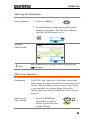
editing function. The ARB function is able to create waveforms with
a 20MHz sampling rate, 4k data points with vertical range of
±511points.
Selecting the
Carrier Shape
1. Press the FUNC key
repeatedly to select the
ARB function.
FUNC
2. Press the Point key.
→
Point
3. Point will flash in the secondary display area.
4. Use the scroll
wheel or keypad to
choose a point
number.
Use the Enter key
to confirm the
point number.
Range
Point:
or
7
8
9
4
5
6
1
2
3
0
Enter
0 ~ 4096
5. Press the Value key.
Point
6. Value will flash in the secondary display
area.
74
/
OPERATION
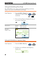
7. Use the scroll
wheel or keypad to
choose the vertical
value of the
selected point.
Use the Enter key
to confirm the
point value.
Range
Value:
or
7
8
9
4
5
6
1
2
3
0
/
Enter
±511 (10-bit vertical resolution)
8. Repeat steps 2 to 7 for the remaining points of
the ARB waveform.
Note
The horizontal position of the points depends on the
set frequency. For example, if the set frequency is 1kHz
(period = 1ms), then each point will be located every
0.01ms (1ms/sample rate).
Example:
Point “0” is set to
+511.
Note
To save the ARB data, please see the Save/Recall
section on page 82.
75
AFG-2000 Series User Manual
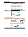
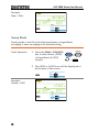
Using the Frequency Counter
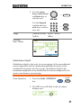
Selecting the Frequency Counter Function
Connection
Panel Operation
Connect the signal source to
Counter input port on the rear
panel.
1. Press the Count key.
OUTPUT
INPUT
MOD
Counter
Trigger
MOD
Gate
Count
2. The current gate time and the Count icon will
appear in the display when the counter
function is active.
The input frequency will be shown in the
frequency display area.
Example: input
frequency of 1kHz
76
OPERATION
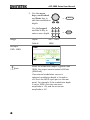
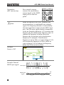
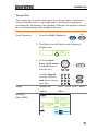
Selecting the Gate Time
Panel Operation
1. Ensure the Count function
is active.
2. Press the Shift + Gate key
repeatedly to select the
desired gate time.
Range
Gate time
Page 76
Gate
Shift
+
Count
0.01s, 0.1s, 1s, 10s
3. The current gate time is displayed in the
counter settings area of the display.
77
AFG-2000 Series User Manual
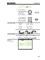
Using the SYNC Output Port
Connecting the SYNC Output Port
Background
The SYNC output port is used as a synchronization
signal for function outputs. All the output signals
apart from the noise output function have a
synchronization signal.
Connection
Connect a BNC cable from the
SYNC output port on the front
panel to the desired input
device.
Note
OUTPUT
SYNC
50W
The SYNC signal is output even when the main
output is not output.
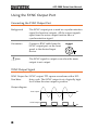
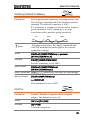
SYNC Output Signal
SYNC Output For SYNC output: TTL square waveform with a 50%
Sine Wave
duty cycle. The SYNC output is at a logically high
level when the sine output is positive.
Output diagram
Sine output
SYNC output
78
0V
0V
OPERATION
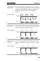
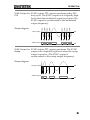
SYNC Output For SYNC output: TTL square waveform with a duty
Square Wave
cycle corresponding to the duty cycle of the output
square wave. The SYNC output is at a logically
high level when the square wave output is
positive.
Output diagram
Square wave
output
SYNC output
0V
0V
SYNC Output For SYNC output: TTL square waveform with a 50%
Ramp Wave
duty cycle. The SYNC output is at a logically high
level when the sine output is positive.
Output diagram
Ramp wave
output
SYNC output
0V
0V
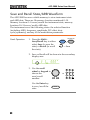
SYNC Output For SYNC output: A single TTL positive pulse at the
ARB Wave
start of each ARB period (pulse width = 1/sample
rate).
Output diagram
ARB output
SYNC output
0V
0V
79
AFG-2000 Series User Manual
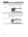
SYNC Output For SYNC output: TTL square waveform with a 50%
AM
duty cycle. The SYNC output is at a logically high
level when the modulated output is positive.
Output diagram
AM output
SYNC output
0V
0V
SYNC Output For SYNC output: TTL square waveform with a 50%
FM
duty cycle. The SYNC output is at a logically high
level when the modulated output is positive (The
SYNC output is synchronized to the modulated
output frequency).
Output diagram
FM output
SYNC output
80
0V
0V
OPERATION
SYNC Output For SYNC output: TTL square waveform with a 50%
FSK
duty cycle. The SYNC output is at a logically high
level when the modulated output is positive (The
SYNC output is synchronized to the modulated
output frequency).
Output diagram
FSK output
SYNC output
0V
0V
SYNC Output For SYNC output: TTL square waveform. The SYNC
Sweep
output is at a logically high level when the sweep
output is positive (The SYNC output is
synchronized to the sweep output frequency).
Output diagram
Sweep output
0V
SYNC output
0V
81
AFG-2000 Series User Manual
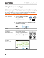
Save and Recall State/ARB Waveform
The AFG-2000 has non-volatile memory to store instrument state
and ARB data. There are 10 memory location numbered 0~19.
Memory locations 0~9 saves/recalls the instrument state, memory
locations 10~19 saves/recalls ARB data.
The instrument saves the following states: the selected function
(including ARB), frequency, amplitude, DC offset, duty
cycle/symmetry, and any of the modulation parameters.
Panel Operation
1. Press the Shift +
Save/Recall key to either
select Save (to save the
state) or Recall (to recall
the state).
Save/Recall
Shift
+
Hz/Vpp
→ Save
2. Save or Recall will be shown in the secondary
display area.
3. Use the scroll
wheel or keypad to
choose the
save/recall
number.
Use the Enter key
to save/recall the
state.
82
or
7
8
9
4
5
6
1
2
3
0
Enter
/
OPERATION
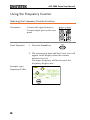
Note
The instrument state can be saved to any 10 (0~9) of
the storage locations. ARB data can be saved to any 10
(10~19) instrument locations.
When a state is saved, it overwrites the previously
saved state in the same location. If ARB data is
recalled, the current state will be overwritten.
A memory location can only be recalled if it has been
previously saved.
Example:
Save State
Example:
Recall State
83
AFG-2000 Series User Manual
REMOTE INTERFACE
Selecting the USB Remote Interface .................................. 86
Remote control terminal connection ................................... 86
Command Syntax ............................................................... 87
Command List ................................................................... 93
System Commands ............................................................ 95
*IDN? ................................................................................... 95
*RST ..................................................................................... 95
Status Register Commands ................................................ 96
*CLS ..................................................................................... 96
Apply Commands .............................................................. 97
SOURce[1]:APPLy:SINusoid ................................................ 99
SOURce[1]:APPLy:SQUare ................................................... 99
SOURce[1]:APPLy:RAMP ................................................... 100
SOURce[1]:APPLy:NOISe................................................... 100
SOURce[1]:APPLy:USER .................................................... 101
SOURce[1]:APPLy? ............................................................. 101
Output Commands .......................................................... 103
SOURce[1]:FUNCtion ........................................................ 103
SOURce[1]:FREQuency ...................................................... 104
SOURce[1]:AMPlitude ........................................................ 106
SOURce[1]:DCOffset .......................................................... 107
SOURce[1]:SQUare:DCYCle............................................... 107
SOURce[1]:RAMP:SYMMetry ............................................ 109
OUTPut .............................................................................. 109
SOURce[1]:OUTPut:SYNC ................................................. 110
SOURce[1]:VOLTage:UNIT ................................................ 111
Amplitude Modulation (AM) Commands ......................... 112
AM Overview ...................................................................... 112
SOURce[1]:AM:STATe ........................................................ 113
SOURce[1]:AM:SOURce .................................................... 113
SOURce[1]:AM:INTernal:FUNCtion .................................. 114
SOURce[1]:AM:INTernal:FREQuency ................................ 114
SOURce[1]:AM:DEPTh ....................................................... 115
84
REMOTE INTERFACE
Frequency Modulation (FM) Commands ......................... 116
FM Overview ...................................................................... 116
SOURce[1]:FM:STATe ........................................................ 116
SOURce[1]:FM:SOURce ..................................................... 117
SOURce[1]:FM:INTernal:FUNCtion ................................... 118
SOURce[1]:FM:INTernal:FREQuency ................................ 118
SOURce[1]:FM:DEViation .................................................. 119
Frequency-Shift Keying (FSK) Commands ........................ 121
FSK Overview ..................................................................... 121
SOURce[1]:FSKey:STATe .................................................... 121
SOURce[1]:FSKey:SOURce ................................................. 122
SOURce[1]:FSKey:FREQuency ........................................... 122
SOURce[1]:FSKey:INTernal:RATE ...................................... 123
Frequency Sweep Commands .......................................... 125
Sweep Overview ................................................................. 125
SOURce[1]:SWEep:STATe .................................................. 126
SOURce[1]:FREQuency:STARt ........................................... 126
SOURce[1]:FREQuency:STOP ............................................ 127
SOURce[1]:SWEep:SPACing............................................... 128
SOURce[1]:SWEep:TIME .................................................... 128
SOURce[1]:SWEep:SOURce ............................................... 129
Arbitrary Waveform Commands ....................................... 130
Arbitrary Waveform Overview ............................................ 130
SOURce[1]:FUNCtion USER .............................................. 131
DATA:DAC .......................................................................... 131
Save and Recall Commands ............................................. 133
*SAV ................................................................................... 133
*RCL ................................................................................... 133
85
AFG-2000 Series User Manual
Selecting the USB Remote Interface
The AFG-2000 uses a USB interface for remote control. Connecting
to USB
USB
configuration
Panel Operation
PC side connector Type A, host
AFG-2000 side
connector
Type Mini B, slave
Speed
1.1/2.0 (full speed)
1. Connect the
Mini USB—USB-A cable
from the PC to the Mini
USB port on the rear panel.
2. When the PC asks for the USB driver, select
XXXXXXX.inf included in the software
package or download the driver from the GW
website, www.gwinstek.com.
3. The USB icon will appear when the USB
connection is active.
Remote control terminal connection
Terminal
application
Invoke the terminal application such as Hyper
Terminal. Make note of the COM port, baud rate,
stop bit, data bit, and parity accordingly from the
Windows Device Manager.
To check the COM port settings, see the Device
Manager in the PC. For WinXP, Control panel →
System → Hardware tab.
86
REMOTE INTERFACE
Functionality
check
Run this query command via the terminal.
*idn?
This should return the Manufacturer, Model
number, Serial number, and Firmware version in
the following format.
GW INSTEK, AFG-2125, SN:XXXXXXXX,Vm.mm
Note
PC Software
^j and ^m can be used as the terminal character
when using a terminal program.
The proprietary PC software, downloadable from
GWInstek website, can be used to download
waveforms.
Command Syntax
Compatible
standard
IEEE488.2, 1992 (fully compatible)
SCPI, 1994 (partially compatible)
Command Tree
The SCPI standard is an ASCII based standard that
defines the command syntax and structure for
programmable instruments.
Commands are based on a hierarchical tree
structure. Each command keyword is a node on
the command tree with the first keyword as the
root node. Each sub node is separated with a
colon.
Shown below is a section of the SOURce[1] root
node and the APPLy/OUTPut and
SINusoid/SQUare sub nodes.
87
AFG-2000 Series User Manual
SOURce[1|2]
:OUTPut
:APPLy
:SINusoid
Command types
88
Root node
:SQUare
2nd node
3rd node
Commands can be separated into three distinct
types, simple commands, compound commands
and queries.
Simple
A single command with/without
a parameter
Example
*OPC
Compound
Two or more commands
separated by a colon (:)
with/without a parameter
Example
SOURce:APPLy:SQUare
Query
A query is a simple or compound
command followed by a question
mark (?). A parameter (data) is
returned. The maximum or
minimum value for a parameter
can also be queried where
applicable.
Example
SOURce1:FREQuency?
SOURce1:FREQuency? MIN
REMOTE INTERFACE
Command forms Commands and queries have two different forms,
long and short. The command syntax is written
with the short form of the command in capitals
and the remainder (long form) in lower case.
long
long
SOURce1:DCOffset
short
short
The commands can be written in capitals or lowercase, just so long as the short or long forms are
complete. An incomplete command will not be
recognized.
Below are examples of correctly written
commands:
LONG:
SOURce1:DCOffset
SOURCE1:DCOFFSET
source1:dcoffset
SHORT: SOUR1:DCO
sour1:dco
Command
Format
SOURce1:DCOffset < offset>LF
1
2
3
4
1: command header
2: single space
3: parameter
4: message terminator
Square Brackets
[]
Commands that contain squares brackets indicate
that the contents are optional. The function of the
command is the same with or without the square
bracketed items. Brackets are not sent with the
command.
For example, the frequency query below can use any of
the following 3 forms:
SOURce1:FREQuency? [MINimum|MAXimum]
SOURce1:FREQuency? MAXimum
89
AFG-2000 Series User Manual
SOURce1:FREQuency? MINimum
SOURce1:FREQuency?
Braces { }
Commands that contain braces indicate one item
within the braces must be chosen. Braces are not
sent with the command.
Angled Brackets
<>
Angle brackets are used to indicate that a value
must be specified for the parameter. See the
parameter description below for details. Angled
brackets are not sent with the command.
Bars |
Bars are used to separate multiple parameter
choices in the command format.
Parameters
Type
Description
Example
<Boolean>
Boolean logic
0, 1/ON,OFF
<NR1>
integers
0, 1, 2, 3
<NR2>
decimal numbers 0.1, 3.14, 8.5
<NR3>
floating point
4.5e-1, 8.25e+1
<NRf>
any of NR1, 2, 3
1, 1.5, 4.5e-1
<NRf+>
<Numeric>
NRf type with a
suffix including
MINimum,
MAXimum or
DEFault
parameters.
1, 1.5, 4.5e-1
<aard>
Arbitrary ASCII
characters.
<discrete>
Discrete ASCII
character
parameters
NRf+ type
<peak deviation including
frequency unit
in Hz>
suffixes.
<rate in Hz>
<frequency>
90
MAX, MIN,
DEF
IMM, EXT,
MAN
1 KHZ, 1.0 HZ,
ΜHZ
REMOTE INTERFACE
<amplitude>
NRf+ type
VPP, dBm,
including voltage Vrms
unit suffixs.
<offset>
NRf+ type
V
including voltage
unit suffixes.
<seconds>
NRf+ type
including time
unit suffixes.
nS, uS, mS, S
<percent>
NRf type
N/A
<depth in
percent>
Message
terminators
Note
Command
Separators
LF CR
line feed code (new line) and
carriage return.
LF
line feed code (new line)
^j or ^m should be used when using a terminal
program.
Space
A space is used to separate a
parameter from a
keyword/command header.
Colon (:)
A colon is used to separate
keywords on each node.
Semicolon (;)
A semicolon can be used to
combine commands from different
node levels.
For example:
SOURce1:PWM:SOURce?
SOURce:PULSe:WIDTh?
SOURce1:PWM:SOURce?;SOURce
:PULSe:WIDTh?
91
AFG-2000 Series User Manual
Comma (,)
When a command uses multiple
parameters, a comma is used to
separate the parameters.
For example:
SOURce:APPLy:SQUare 10KHZ,2.0
VPP,-1VDC
92
REMOTE INTERFACE
Command List
System Commands ............................................................ 95
*IDN? ................................................................................... 95
*RST...................................................................................... 95
Status Register Commands ............................................... 96
*CLS...................................................................................... 96
Apply Commands .............................................................. 97
SOURce[1]:APPLy:SINusoid ................................................. 99
SOURce[1]:APPLy:SQUare ................................................... 99
SOURce[1]:APPLy:RAMP .................................................... 100
SOURce[1]:APPLy:NOISe ................................................... 100
SOURce[1]:APPLy:USER ..................................................... 101
SOURce[1]:APPLy? ............................................................. 101
Output Commands .......................................................... 103
SOURce[1]:FUNCtion ......................................................... 103
SOURce[1]:FREQuency ...................................................... 104
SOURce[1]:AMPlitude ........................................................ 106
SOURce[1]:DCOffset .......................................................... 107
SOURce[1]:SQUare:DCYCle ............................................... 107
SOURce[1]:RAMP:SYMMetry ............................................. 109
OUTPut............................................................................... 109
SOURce[1]:OUTPut:SYNC ................................................. 110
SOURce[1]:VOLTage:UNIT ................................................ 111
Amplitude Modulation (AM) Commands ......................... 112
AM Overview ...................................................................... 112
SOURce[1]:AM:STATe ........................................................ 113
SOURce[1]:AM:SOURce ..................................................... 113
SOURce[1]:AM:INTernal:FUNCtion .................................. 114
SOURce[1]:AM:INTernal:FREQuency ................................ 114
SOURce[1]:AM:DEPTh ....................................................... 115
Frequency Modulation (FM) Commands ......................... 116
FM Overview ...................................................................... 116
SOURce[1]:FM:STATe ........................................................ 116
SOURce[1]:FM:SOURce ..................................................... 117
SOURce[1]:FM:INTernal:FUNCtion ................................... 118
SOURce[1]:FM:INTernal:FREQuency ................................ 118
SOURce[1]:FM:DEViation .................................................. 119
Frequency-Shift Keying (FSK) Commands ........................ 121
FSK Overview ..................................................................... 121
SOURce[1]:FSKey:STATe .................................................... 121
SOURce[1]:FSKey:SOURce ................................................. 122
SOURce[1]:FSKey:FREQuency ........................................... 122
93
AFG-2000 Series User Manual
SOURce[1]:FSKey:INTernal:RATE ...................................... 123
Frequency Sweep Commands........................................... 125
Sweep Overview ................................................................. 125
SOURce[1]:SWEep:STATe .................................................. 126
SOURce[1]:FREQuency:STARt ........................................... 126
SOURce[1]:FREQuency:STOP ............................................ 127
SOURce[1]:SWEep:SPACing .............................................. 128
SOURce[1]:SWEep:TIME ................................................... 128
SOURce[1]:SWEep:SOURce............................................... 129
Arbitrary Waveform Commands ....................................... 130
Arbitrary Waveform Overview ............................................ 130
SOURce[1]:FUNCtion USER .............................................. 131
DATA:DAC.......................................................................... 131
Save and Recall Commands ............................................. 133
*SAV ................................................................................... 133
*RCL ................................................................................... 133
94
REMOTE INTERFACE
System Commands
*IDN?
Description
Query
Returns the function generator manufacturer,
model number, serial number and firmware
version number in the following format:
GW INSTEK,AFG-2025,SN:XXXXXXXX,Vm.mm
Query Syntax
IDN?
Return parameter <string>
Query Example
*IDN?
>GW INSTEK,AFG-2025,SN:XXXXXXXX,Vm.mm
Returns the identification of the function
generator.
*RST
Description
Note
Syntax
Set
Reset the function generator to its factory default
state.
Note the *RST command will not delete
instrument save states/ARB waveforms in
memory.
*RST
95
AFG-2000 Series User Manual
Status Register Commands
*CLS
Set
Description
The *CLS command clears all the event registers,
the error queue and cancels an *OPC command.
Syntax
*CLS
96
REMOTE INTERFACE
Apply Commands
The APPLy command has 5 different types of outputs (Sine, Square,
Ramp, Noise, User(ARB)). The Apply command is the quickest,
easiest way to output waveforms remotely. Frequency, amplitude
and offset can be specified for each function.
As only basic parameters can be set with the Apply command, other
parameters, such as duty and symmetry use the instrument default
values.
The Apply command will set the trigger source to immediate and
disable modulation and sweep modes, if active. The command also
turns on the output command SOURce[1]:OUTP ON.
As the frequency, amplitude and offset parameters are in nested
square brackets, the amplitude can only be specified if the frequency
has been specified and the offset can only be specified if the
amplitude has been set. See the syntax below for the example:
SOURce1:APPLy:<function> [<frequency> [,<amplitude>
[,<offset>] ]]
Output Frequency For the output frequency, MINimum, MAXimum
and DEFault can be used instead of specifying a
frequency. The default frequency for all functions
is set to 1 kHz.
The maximum and minimum frequency depends
on the function used and the model of the
frequency generator. If a frequency output that is
out of range is specified, the max/min frequency
will be used instead. A ―-222‖ error will be
generated from the remote terminal.
Function
Min frequency
Max frequency
Sine
0.1Hz
25MHz*
97
AFG-2000 Series User Manual
Square
0.1Hz
25MHz*
Ramp
0.1Hz
1MHz
Noise
Not applicable
Not applicable
User (ARB)
0.1Hz
20MHz*
*The AFG-2005/2105 is limited to 5MHz, the AFG2012/2112 is limited to 12MHz.
Output
Amplitude
When setting the amplitude, MINimum,
MAXimum and DEFault can be used instead of
specifying an amplitude. The range depends on
the function being used. The default amplitude for
all functions is 100 mVpp (into 50Ω).
Vrms, dBm or Vpp units can be used to specify the
output units to use with the current command.
Note, however, that the VOLT:UNIT command
can be used to set the default units (Vrms, dBm,
Vpp) for all commands. This will be applicable to
the Apply command when no unit is specified. The
unit default is set to Vpp.
The output amplitude can be affected by the
function and unit chosen. Vpp and Vrms or dBm
values may have different maximum values due to
differences such as crest factor. For example, a
5Vrms square wave will be adjusted to 3.536 Vrms
for a sine wave.
DC Offset voltage The offset parameter can be set to MINimum,
MAXimum or DEFault instead of a specified DC
offset value. The default DC offset is 0 volts.
The maximum and minimum DC offset is limited
by the output amplitude as shown below.
|Voffset| < Vmax – Vpp/2
98
REMOTE INTERFACE
This means that the magnitude of the DC offset is
determined by the output amplitude.
If the specified DC offset is out of range, the
maximum/minimum offset will be set instead. A
―-222‖ error will be generated from the remote
terminal.
SOURce[1]:APPLy:SINusoid
Set
Description
Outputs a sine wave when the command has
executed. Frequency, amplitude and offset can also
be set.
Syntax
SOURce[1]:APPLy:SINusoid [<frequency>
[,<amplitude> [,<offset>] ]]
Parameter
<frequency>
0.1Hz~25MHz*
<amplitude>
1mV~10Vpp (50Ω)
<offset>
-5V ~ +5V (50Ω)
*AFG-2005/2105 limited to 5MHz, AFG-2012/2112
limited to 12MHz.
Example
SOURce1:APPL:SIN MAX, 3.0, -2.5
Outputs a 3Vpp sine wave at 25MHz (max
frequency) with a -2.5V offset.
SOURce[1]:APPLy:SQUare
Set
Description
Outputs a square wave when the command has
executed. Frequency, amplitude and offset can also
be set. The duty cycle is fixed to 50%.
Syntax
SOURce[1]:APPLy:SQUare [<frequency> [,<amplitude>
[,<offset>] ]]
Parameter
<frequency>
0.1Hz ~ 25MHz*
<amplitude>
1mV~10V (50Ω)
99
AFG-2000 Series User Manual
<offset>
-5V ~ +5V (50Ω)
*AFG-2005/2105 limited to 5MHz, AFG-2012/2112
limited to 12MHz.
Example
SOURce1:APPL:SQU MAX, DEF, DEF
Outputs a 100mVpp (DEF) square wave at 25MHz
with 0 offset (DEF).
SOURce[1]:APPLy:RAMP
Set
Description
Outputs a ramp wave when the command has
executed. Frequency, amplitude and offset can also
be set. The symmetry is fixed to 100%.
Syntax
SOURce[1]:APPLy:RAMP [<frequency> [,<amplitude>
[,<offset>] ]]
Parameter
<frequency>
0.1Hz~1MHz
<amplitude>
1mV~10V (50Ω)
<offset>
-5V ~ +5V (50Ω)
Example
SOUR1:APPL:RAMP 2KHZ,MAX,MAX
Sets the frequency to 2kHz and sets the amplitude
and offset to the maximum.
SOURce[1]:APPLy:NOISe
Description
Note
Set
Outputs Gaussian noise with a 20 MHz
bandwidth. Amplitude and offset can also be set.
The Frequency parameter is not used with the
noise function; however a value (or DEFault) must
still be specified. The frequency is remembered for
the next function used.
Syntax
SOURce[1]:APPLy:NOISe [<frequency|DEFault>
[,<amplitude> [,<offset>] ]]
Parameter
<frequency>
0.1Hz~20MHz*
<amplitude>
1mV~10V (50Ω)
100
REMOTE INTERFACE
<offset>
-5V ~ +5V (50Ω)
*AFG-2005/2105 limited to 5MHz, AFG-2012/2112
limited to 12MHz.
Example
SOURce[1|2]:APPL:NOIS DEF, 5.0, 2.0
Sets the amplitude to 5 volts with an offset of 2
volts.
SOURce[1]:APPLy:USER
Description
Note
Set
Outputs an arbitrary waveform that is specified
from the FUNC:USER command.
Frequency and amplitude values are not used with
this function; however a value (or DEFault) must
be specified. The values are remembered for the
next function used.
Syntax
SOURce[1]:APPLy:USER [<frequency> [,<amplitude>
[,<offset>] ]]
Parameter
<frequency>
0.1Hz~10MHz
<amplitude>
1mV~10V (50Ω)
<offset>
-5V ~ +5V (50Ω)
Example
SOUR1:APPL:USER
Outputs the ARB waveform specified in the
FUNC:USER command.
SOURce[1]:APPLy?
Description
Note
Query Syntax
Query
Outputs a string with the current settings.
The returned string can be passed back, when
appended to the Apply Command. This is
intended to be used to return the function
generator to a known state.
I.e., SOURce[1]:APPL:<passed back string>
SOURce[1]:APPLy?
101
AFG-2000 Series User Manual
Return Parameter <string>
Query Example
Function(<NRf>), frequency(<NRf>),
amplitude(<NRf>),offset(<NRf>)
SOUR1:APPL?
>SIN +5.0000000000000E+03,+3.0000E+00,-2.50E+00
Returns a string with the current function and
parameters, Sine, 5kHz, 3Vpp, -2.5V offset.
102
REMOTE INTERFACE
Output Commands
Unlike the Apply commands, the Output commands are low level
commands to program the function generator.
This section describes the low-level commands used to program the
function generator. Even though the APPLy command is the easiest
way to program the function generator, it lacks the ability to change
individual parameters. The Output commands on the other hand
can be used to set individual parameters, or those parameters that
cannot be programmed with the Apply command.
Set
SOURce[1]:FUNCtion
Description
Note
Query
The FUNCtion command selects and outputs the
selected output function. The User parameter
outputs an arbitrary waveform previously set by
the SOURce[1]:FUNC:USER command.
The previously set frequency, amplitude and offset
values are used automatically.
If the function mode is changed and the current
frequency setting is not supported by the new
mode, the frequency setting will be altered to the
next highest value.
Vpp and Vrms or dBm amplitude values may have
different maximum values due to differences such
as crest factor. For example, if a 5Vrms square
wave is changed to a sinewave, then the Vrms
value is automatically adjusted to 3.536Vrms.
The modulation and sweep modes can only be
used with some of the basic waveforms. If a mode
is not supported, the conflicting mode will be
disabled. See the table below.
Sine
Square
Ramp
Noise
ARB
AM
FM
103
AFG-2000 Series User Manual
FSK
SWEEP
Syntax
SOURce[1]:FUNCtion {SINusoid|SQUare|RAMP
|NOISe |USER}
Example
SOUR1:FUNC SIN
Sets the output as a sine function.
Query Syntax
SOURce[1]:FUNCtion?
Return Parameter SIN, SQU, RAMP, NOIS,
USER
Query Example
Returns the current output
type.
SOUR1:FUNC?
>SIN
Current output is sine.
Set
SOURce[1]:FREQuency
Description
Note
Query
Sets the output frequency for the
SOURce[1]:FUNCtion command. The query
command returns the current frequency setting.
The maximum and minimum frequency depends
on the function mode.
Sine, Square
Ramp
0.1Hz~25MHz*
Noise
Not applicable
User
0.1Hz~10MHz*
0.1Hz~10MHz
0.1Hz ~ 1MHz
*AFG-2005/2105 limited to 5MHz, AFG-2012/2112
limited to 12MHz.
104
REMOTE INTERFACE
If the function mode is changed and the current
frequency setting is not supported by the new
mode, the frequency setting will be altered to the
next highest value.
The duty cycle of square waveforms depends on
the frequency settings:
1% to 99% (frequency < 100KHz)
20% to 80% (100KHz < frequency < 5 MHz)
40% to 60% (5 MHz < frequency < 10 MHz)
50% (frequency > 10 MHz)
If the frequency is changed and the set duty cycle
cannot support the new frequency, the highest
duty cycle available at that frequency will be used.
A ―-221‖ error will be generated from the remote
terminal.
Syntax
SOURce[1]:FREQuency
{<frequency>|MINimum|MAXimum}
Example
SOUR1:FREQ MAX
Sets the frequency to the maximum for the current
mode.
Query Syntax
SOURce[1]:FREQuency?
Return Parameter <NR3>
Query Example
Returns the frequency for the current
mode.
SOUR1:FREQ? MAX
>+1.0000000000000E+03
The maximum frequency that can be set for the
current function is 1MHz.
105
AFG-2000 Series User Manual
Set
SOURce[1]:AMPlitude
Description
Note
Query
Sets the output amplitude for the
SOURce[1]:FUNCtion command. The query
command returns the current amplitude settings.
The maximum and minimum amplitude depends
on the output termination. The default amplitude
for all functions is 100 mVpp (50Ω).
The offset and amplitude are related by the
following equation.
|Voffset| < Vmax – Vpp/2
The output amplitude can be affected by the
function and unit chosen. Vpp and Vrms or dBm
values may have different maximum values due to
differences such as crest factor. For example, a
5Vrms square wave will be adjusted to 3.536 Vrms
for a sine wave.
The amplitude units can be explicitly used each
time the SOURce[1]:AMPlitude command is used.
Alternatively, the VOLT:UNIT command can be
used to set the amplitude units for all commands.
Syntax
SOURce[1]:AMPlitude {< amplitude>
|MINimum|MAXimum}
Example
SOUR1:AMP MAX
Sets the amplitude to the maximum for the current
mode.
Query Syntax
SOURce[1]:AMPlitude? {MINimum|MAXimum}
Return Parameter <NR3>
Query Example
SOUR1:AMP? MAX
>+5.0000E+00
106
Returns the amplitude for the current
mode.
REMOTE INTERFACE
The maximum amplitude that can be set for the
current function is 5 volts.
Set
SOURce[1]:DCOffset
Description
Note
Query
Sets or queries the DC offset for the current mode.
The offset parameter can be set to MINimum or
MAXimum. The default offset is 0 volts. The offset
is limited by the output amplitude as shown
below.
|Voffset| < Vmax – Vpp/2
If the output specified is out of range, the
maximum offset will be set.
The maximum offset is ±5V into 50Ω).
Syntax
SOURce[1]:DCOffset {< offset>
|MINimum|MAXimum}
Example
SOUR1:DCO MAX
Sets the offset to the maximum for the current
mode.
Query Syntax
SOURce[1]:DCOffset? {MINimum|MAXimum}
Return Parameter <NR3>
Query Example
Returns the offset for the current mode.
SOUR1:DCO?
>+3.0000E+00
The offset for the current mode is set to +3 volts.
Set
SOURce[1]:SQUare:DCYCle
Description
Note
Query
Sets or queries the duty cycle for square waves
only. The setting is remembered if the function
mode is changed. The default duty cycle is 50%.
The duty cycle of square waveforms depend on the
frequency settings.
107
AFG-2000 Series User Manual
1% to 99% (frequency < 100KHz)
20% to 80% (100KHz < frequency < 5 MHz)
40% to 60% (5 MHz < frequency < 10 MHz)
50% (frequency > 10 MHz
If the frequency is changed and the set duty cycle
cannot support the new frequency, the highest
duty cycle available at that frequency will be used.
A ―-221‖ error will be generated from the remote
terminal.
For square waveforms, the Apply command and
AM/FM modulation modes ignore the duty cycle
settings.
Syntax
SOURce[1]:SQUare:DCYCle {< percent>
|MINimum|MAXimum}
Example
SOUR1:SQU:DCYC MAX
Sets the duty cycle to the highest possible for the
current frequency.
Query Syntax
SOURce[1]:SQUare:DCYCle? {MINimum|MAXimum}
Return Parameter <NR3>
Query Example
Returns the duty cycle as a percentage.
SOUR1:SQU:DCYC?
>+5.00E+01
The duty cycle is set 50%.
108
REMOTE INTERFACE
Set
SOURce[1]:RAMP:SYMMetry
Description
Sets or queries the symmetry for ramp waves only.
The setting is remembered if the function mode is
changed. The default symmetry is 100%.
0% symmetry is a ramp waveform with a negative
going transition. 100% symmetry is a ramp
waveform with a positive going transition.
0%
Note
Query
50%
100%
For ramp waveforms, the Apply command and
AM/FM modulation modes ignore the current
symmetry settings.
Syntax
SOURce[1]:RAMP:SYMMetry {< percent>
|MINimum|MAXimum}
Example
SOUR[1]:RAMP:SYMM MAX
Sets the symmetry to the 100%.
Query Syntax
SOURce[1]:RAMP:SYMMetry?
{MINimum|MAXimum}
Return Parameter <NR3>
Query Example
Returns the symmetry as a percentage.
SOUR1:RAMP:SYMMetry?
>+1.0000E+02
The symmetry is set as 100%.
Set
OUTPut
Query
Description
Enables/Disables or queries the front panel
output. The default is set to off.
Syntax
OUTPut {OFF|ON}
Example
OUTP ON
Turns the output on.
109
AFG-2000 Series User Manual
Query Syntax
OUTPut?
Return Parameter 1
ON
0
OFF
Query Example
OUTP?
>1
The output is currently on.
Set
SOURce[1]:OUTPut:SYNC
Description
Query
Turns the SYNC output port on the front panel
on/off.
By default the SYNC port is turned on.
Syntax
SOURce[1]:OUTPut:SYNC{OFF|ON}
Example
SOUR:OUTP:SYNC OFF
Turns the SYNC output port off.
Query Syntax
SOURce[1]:OUTPut:SYNC?
Return Parameter 1
The SYNC port is on.
0
The SYNC port is off.
Query Example
SOUR:OUTP:SYNC?
>0
The SYNC output port is off.
110
REMOTE INTERFACE
Set
SOURce[1]:VOLTage:UNIT
Description
Note
Query
Sets or queries the output amplitude units. There
are three types of units: VPP, VRMS and DBM. The
SOURce[1]:VOLTage:UNIT command does not set
the offset units.
The units set with the VOLTage:UNIT command
will be used as the default unit for all amplitude
units unless a different unit is specifically used for
a command, such as those used with the Apply
commands.
Syntax
SOURce[1]:VOLTage:UNIT {VPP|VRMS|DBM}
Example
SOUR1:VOLT:UNIT VPP
Sets the amplitude units to Vpp.
Query Syntax
SOURce[1]:VOLTage:UNIT?
Return Parameter VPP
Query Example
Vpp
VRMS
Vrms
DBM
dBm
SOUR1:VOLT:UNIT?
>VPP
The amplitude units are set to Vpp.
111
AFG-2000 Series User Manual
Amplitude Modulation (AM) Commands
AM Overview
To successfully create an AM waveform, the following commands
must be executed in order.
Enable AM
Modulation
Configure Carrier
1. Turn on AM modulation using the
SOURce[1]:AM:STAT ON command
2. Use the APPLy command to select a carrier
waveform. Alternatively the equivalent
FUNC, FREQ, AMP, and DCO commands
can be used to create a carrier waveform with
a designated frequency, amplitude and offset.
Sine, square or ramp can be used as the
carrier wave.
Select
Modulation
Source
3. Select an internal or external modulation
source using the SOURce[1]:AM:SOUR
command.
Select Shape
4. Use the SOURce[1]:AM:INT:FUNC command
to select a Sine, Square or Ramp modulating
waveform. For internal sources only.
Set Modulating
Frequency
5. Set the modulating frequency using the
SOURce[1]:AM:INT:FREQ command. For
internal sources only.
Set Modulation
Depth
6. Set the modulation depth using the
SOURce[1]:AM:DEPT command.
112
REMOTE INTERFACE
Set
SOURce[1]:AM:STATe
Description
Note
Query
Sets or disables AM modulation. By default AM
modulation is disabled. AM modulation must be
enabled before setting other parameters.
As only one mode is allowed at any one time,
other modulation modes (inc. Sweep/FSK) will be
disabled when AM modulation is enabled.
Syntax
SOURce[1]:AM:STATe {OFF|ON}
Example
SOUR1:AM:STAT ON
Enables AM modulation.
Query Syntax
SOURce[1]:AM:STATe?
Return Parameter 0
1
Query Example
Disabled (OFF)
Enabled (ON)
SOUR1:AM:STAT?
>1
AM modulation mode is currently enabled.
Set
SOURce[1]:AM:SOURce
Description
Note
Query
Sets or queries the modulation source as internal
or external. Internal is the default modulation
source.
If an external modulation source is selected,
modulation depth is limited to ± 5V from the MOD
input port on the rear panel. For example, if
modulation depth is set to 100%, then the
maximum amplitude is +5V, and the minimum
amplitude is -5V.
Syntax
SOURce[1]:AM:SOURce {INTernal|EXTernal}
Example
SOUR1:AM:SOUR EXT
Sets the modulation source to external.
113
AFG-2000 Series User Manual
Query Syntax
SOURce[1]:AM:SOURce?
Return Parameter INT
Internal
EXT
External
Query Example
SOUR1:AM:SOUR?
>INT
The modulation source is set to internal.
Set
SOURce[1]:AM:INTernal:FUNCtion
Description
Note
Query
Sets the shape of the modulating waveform from
sine, square or ramp. The default shape is sine.
Square waveforms have a 50% duty cycle. Ramp
waveforms have a symmetry of 100%.
Syntax
SOURce[1]:AM:INTernal:FUNCtion
{SINusoid|SQUare| RAMP }
Example
SOUR1:AM:INT:FUNC SIN
Sets the AM modulating wave shape to sine.
Query Syntax
SOURce[1]:AM:INTernal:FUNCtion?
Return Parameter SIN
Query Example
Sine
SQU
Square
RAMP
Ramp
SOUR1:AM:INT:FUNC?
>SIN
The shape for the modulating waveform is Sine.
Set
SOURce[1]:AM:INTernal:FREQuency
Query
Description
Sets the frequency of the internal modulating
waveform only. The default frequency is 100Hz.
Syntax
SOURce[1]:AM:INTernal:FREQuency
{<frequency>|MINimum|MAXimum}
114
REMOTE INTERFACE
Parameter
<frequency>
2 mHz~ 20 kHz
Example
SOUR1:AM:INT:FREQ +1.0000E+02
Sets the modulating frequency to 100Hz.
Query Syntax
SOURce[1]:AM:INTernal:FREQuency?
[MINimum|MAXimum]
Return Parameter <NR3>
Query Example
Returns the frequency in
Hz.
SOUR1:AM:INT:FREQ? MIN
>+1.0000E+02
Returns the minimum frequency allowed.
Set
SOURce[1]:AM:DEPTh
Description
Note
Query
Sets or queries the modulation depth for internal
sources only. The default is 100%.
The function generator will not output more than
±5V, regardless of the modulation depth.
The modulation depth of an external source is
controlled using the ±5V MOD input port on the
rear panel, and not the SOURce[1]:AM:DEPTh
command.
Syntax
SOURce[1]:AM:DEPTh {<depth in percent>
|MINimum|MAXimum}
Parameter
<depth in percent>
Example
SOUR1:AM:DEPT 50
0~120%
Sets the modulation depth to 50%.
Query Syntax
SOURce[1]:AM:DEPTh? [MINimum|MAXimum]
Return Parameter <NR3>
Query Example
Return the modulation depth as a
percentage.
SOUR1:AM:DEPT?
>+1.0000E+02
The modulation depth is 100%.
115
AFG-2000 Series User Manual
Frequency Modulation (FM) Commands
FM Overview
The following is an overview of the steps required to generate an
FM waveform.
Enable FM
Modulation
Configure Carrier
1. Turn on FM modulation using the
SOURce[1]: FM:STAT ON command.
2. Use the APPLy command to select a carrier
waveform. Alternatively, the FUNC, FREQ,
AMPl, and DCOffs commands can be used to
create a carrier waveform with a designated
frequency, amplitude and offset.
Select
Modulation
Source
3. Select an internal or external modulation
source using the SOURce[1]:FM:SOUR
command.
Select shape
4. Use the SOURce[1]:FM:INT:FUNC command
to select a sine, square or ramp modulating
waveform. For internal sources only.
Set Modulating
Frequency
Set Peak
Frequency
Deviation
5. Set the modulating frequency using the
SOURce[1]: FM:INT:FREQ command. For
internal sources only.
6. Use the SOURce[1]:FM:DEV command to set
the frequency deviation.
Set
SOURce[1]:FM:STATe
Description
116
Query
Sets or disables FM modulation. By default FM
modulation is disabled. FM modulation must be
enabled before setting other parameters.
REMOTE INTERFACE
Note
As only one mode is allowed at any one time,
other modes (AM, FSK, Sweep etc.) will be
disabled when FM modulation is enabled.
Syntax
SOUR[1]:FM:STATe {OFF|ON}
Example
SOUR1:FM:STAT ON
Enables FM modulation.
Query Syntax
SOURce[1]:FM:STATe?
Return Parameter 0
1
Query Example
Disabled (OFF)
Enabled (ON)
SOUR1:FM:STAT?
>1
FM modulation mode is currently enabled.
Set
SOURce[1]:FM:SOURce
Description
Note
Query
Sets or queries the modulation source as internal
or external. Internal is the default modulation
source.
If an external modulation source is selected, the
frequency deviation is limited to ± 5V from the
MOD input port on the rear panel. For example, if
frequency deviation is set to 100Hz, then +5V will
increases the frequency by 100Hz.
Syntax
SOURce[1]:FM:SOURce {INTernal|EXTernal}
Example
SOUR1:FM:SOUR EXT
Sets the modulation source to external.
Query Syntax
SOURce[1]:FM:SOURce?
Return Parameter INT
Internal
EXT
External
Query Example
SOUR1:FM:SOUR?
>INT
117
AFG-2000 Series User Manual
The modulation source is set to internal.
Set
SOURce[1]:FM:INTernal:FUNCtion
Description
Note
Query
Sets the shape of the modulating waveform from
sine, square or ramp. The default shape is sine.
Square waveforms have a 50% duty cycle. Ramp
waveforms have a symmetry of 100%.
Syntax
SOURce[1]:FM:INTernal:FUNCtion
{SINusoid|SQUare|RAMP }
Example
SOUR1:FM:INT:FUNC SIN
Sets the FM modulating wave shape to sine.
Query Syntax
SOURce[1]:FM:INTernal:FUNCtion?
Return Parameter SIN
Query Example
Sine
SQU
Square
RAMP
Ramp
SOUR1:FM:INT:FUNC?
>SIN
The shape for the modulating waveform is Sine.
Set
SOURce[1]:FM:INTernal:FREQuency
Query
Description
Sets the frequency of the internal modulating
waveform only. The default frequency is 10Hz.
Syntax
SOURce[1]:FM:INTernal:FREQuency
{<frequency>|MINimum|MAXimum}
Parameter
<frequency> 2 mHz ~ 20 kHz
Example
SOUR1:FM:INT:FREQ +1.0000E+02
Sets the modulating frequency to 100Hz.
Query Syntax
118
SOURce[1]:FM:INTernal:FREQuency?
[MINimum|MAXimum]
REMOTE INTERFACE
Return Parameter <NR3>
Query Example
Returns the frequency in Hz.
SOUR1:FM:INT:FREQ? MAX
>+2.0000E+04
Returns the maximum frequency allowed.
Set
SOURce[1]:FM:DEViation
Description
Query
Sets or queries the peak frequency deviation of the
modulating waveform from the carrier waveform.
The default peak deviation is 100Hz.
The frequency deviation of external sources is
controlled using the ±5V MOD INPUT terminal on
the rear panel. A positive signal (>0~+5V) will
increase the deviation (up to the set frequency
deviation), whilst a negative voltage will reduce
the deviation.
Note
The relationship of peak deviation to modulating
frequency and carrier frequency is shown below.
Peak deviation = modulating frequency – carrier
frequency.
The carrier frequency must be greater than or
equal to the peak deviation frequency. The sum of
the deviation and carrier frequency must not
exceed the maximum frequency for a specific
carrier shape + 1kHz. If an out of range deviation
is set for any of the above conditions, the deviation
will be automatically adjusted to the maximum
value allowed and an ―out of range‖ error will be
generated.
For square wave carrier waveforms, the deviation
may cause the duty cycle frequency boundary to
be exceeded. In these conditions the duty cycle will
be adjusted to the maximum allowed and a ―-221‖
error will be generated.
119
AFG-2000 Series User Manual
Syntax
SOURce[1]:FM:DEViation {<peak deviation in
Hz>|MINimum|MAXimum}
Parameter
<peak deviation in Hz>
DC ~ 25MHz*
DC~1MHz (Ramp)
*Limited to 12MHz for AFG-2112, 5MHz for
AFG-2105.
Example
SOUR1:FM:DEV MAX
Sets the frequency deviation to the maximum
value allowed.
Query Syntax
SOURce[1]:FM:DEViation? [MINimum|MAXimum]
Return Parameter <NR3>
Query Example
Returns the frequency
deviation in Hz.
SOURce[1]:FM:DEViation? MAX
>+1.0000E+06
The maximum frequency deviation for the current
function is 1MHz.
120
REMOTE INTERFACE
Frequency-Shift Keying (FSK) Commands
FSK Overview
The following is an overview of the steps required to generate an
FSK modulated waveform.
Enable FSK
Modulation
1. Turn on FSK modulation using the
SOURce[1]: FSK:STAT ON command.
Configure Carrier
2. Use the APPLy command to select a carrier
waveform. Alternatively, the FUNC, FREQ,
AMPl, and DCOffs commands can be used to
create a carrier waveform with a designated
frequency, amplitude and offset. The carrier
waveform can be sine, square or ramp.
Select FSK Source
3. Select an internal or external modulation
source using the SOURce[1]:FSK:SOUR
command.
Select FSK HOP
Frequency
Set FSK Rate
4. Set the hop frequency using the
SOURce[1]:FSK:FREQ command.
5. Use the SOURce[1]: FSK:INT:RATE
command to set the FSK rate. The FSK rate
can only be set for internal sources.
Set
SOURce[1]:FSKey:STATe
Description
Note
Syntax
Query
Turns FSK Modulation on or off. By default FSK
modulation is off.
As only one mode is allowed at any one time,
other modes (AM, FM, Sweep etc.) will be disabled
when FSK modulation is enabled.
SOURce[1]:FSKey:STATe {OFF|ON}
121
AFG-2000 Series User Manual
Example
SOUR1:FSK:STAT ON
Enables FSK modulation.
Query Syntax
SOURce[1]:FSKey:STATe?
Return Parameter 0
1
Query Example
Disabled (OFF)
Enabled (ON)
SOUR1:FSK:STAT?
>1
FSK modulation is currently enabled.
Set
SOURce[1]:FSKey:SOURce
Description
Note
Query
Sets or queries the FSK source as internal or
external. Internal is the default source.
If an external FSK source is selected, FSK rate is
controlled by the Trigger input port on the rear
panel.
Syntax
SOURce[1]:FSKey:SOURce {INTernal|EXTernal}
Example
SOUR1:FSK:SOUR EXT
Sets the FSK source to external.
Query Syntax
SOURce[1]:FSKey:SOURce?
Return Parameter INT
Internal
EXT
External
Query Example
SOUR1:FSK:SOUR?
>INT
The FSK source is set to internal.
Set
SOURce[1]:FSKey:FREQuency
Description
122
Query
Sets the FSK hop frequency. The default hop
frequency is set to 100Hz.
REMOTE INTERFACE
Note
For FSK, the modulating waveform is a square
wave with a duty cycle of 50%.
Syntax
SOURce[1]:FSKey:FREQuency
{<frequency>|MINimum|MAXimum}
Parameter
<frequency> 0.1Hz~ 25MHz*
0.1Hz~ 1MHz (Ramp)
*AFG-2112 limited to 12MHz, AFG-2105 limited to
5MHz.
Example
SOUR1:FSK:FREQ +1.0000E+02
Sets the FSK hop frequency to 100Hz.
Query Syntax
SOURce[1]:FSKey:FREQuency?
[MINimum|MAXimum]
Return Parameter <NR3>
Query Example
Returns the frequency in Hz.
SOUR1:FSK:FREQ? MAX
>+2.0000E+07
Returns the maximum hop frequency allowed.
Set
SOURce[1]:FSKey:INTernal:RATE
Description
Note
Query
Sets or queries the FSK rate for internal sources
only.
External sources will ignore this command.
Syntax
SOURce[1]:FSKey:INTernal:RATE {<rate in Hz>
|MINimum|MAXimum}
Parameter
<rate in Hz> 2 mHz~100 kHz
Example
SOUR1:FSK:INT:RATE MAX
Sets the rate to the maximum (100kHz).
Query Syntax
SOURce[1]:FSKey:INTernal:RATE?
[MINimum|MAXimum]
Return Parameter <NR3>
Returns the FSK rate in Hz.
123
AFG-2000 Series User Manual
Query example
SOUR1:FSK:INT:RATE?
>+1.0000E+05
Returns the FSK rate (100kHz).
124
REMOTE INTERFACE
Frequency Sweep Commands
Sweep Overview
Below shows the order in which commands must be executed to
perform a sweep.
Enable Sweep
Mode
1. Turn on Sweep mode using the
SOURce[1]: SWE:STAT ON command.
Select waveform
shape, amplitude
and offset
2. Use the APPLy command to select the
waveform shape. Alternatively, the FUNC,
FREQ, AMPl, and DCOffs commands can be
used to create a waveform (sine, square,
ramp) with a designated frequency,
amplitude and offset.
Select Sweep
Boundaries
3. Set the frequency boundaries by setting the
start and stop frequencies.
Start~Stop Use the SOURce[1]:FREQ:STAR
and SOURce[1]:FREQ:STOP to set
the start and stop frequencies. To
sweep up, set the stop frequency
higher than the start frequency. To
sweep down, set the start
frequency higher than the stop
frequency.
Select Sweep
Mode
4. Choose Linear or Logarithmic spacing using
the SOURce[1]:SWE:SPAC command.
Select Sweep
Time
5. Choose the sweep time (rate) using the
SOURce[1]:SWE:TIME command.
Select the sweep
trigger source
6. Select an internal or external sweep trigger
source using the SOURce[1]:SOUR command.
125
AFG-2000 Series User Manual
Set
SOURce[1]:SWEep:STATe
Description
Note
Query
Sets or disables Sweep mode. By default sweep is
disabled. Sweep must be enabled before setting
other parameters.
Any modes will be disabled if sweep mode is
enabled.
Syntax
SOURce[1]:SWEep:STATe {OFF|ON}
Example
SOUR1:SWE:STAT ON
Enables sweep mode.
Query Syntax
SOURce[1]:SWEep:STATe?
Return Parameter 0
1
Query Example
Disabled (OFF)
Enabled (ON)
SOUR1:SWE:STAT?
>1
Sweep mode is currently enabled.
Set
SOURce[1]:FREQuency:STARt
Description
Note
Query
Sets the start frequency of the sweep. 100Hz is the
default start frequency.
To sweep up set the stop frequency higher than the
start frequency. Set the stop frequency lower than
the start frequency to sweep down.
Syntax
SOURce[1]:FREQuency:STARt
{<frequency>|MINimum|MAXimum}
Parameter
<frequency> 0.1Hz ~ 25MHz*
0.1Hz ~ 1MHz (Ramp)
*AFG-2112 limited to 12MHz, AFG-2105 limited to
5MHz.
126
REMOTE INTERFACE
Example
SOUR1:FREQ:STAR +2.0000E+03
Sets the start frequency to 2kHz.
Query Syntax
SOURce[1]:FREQuency:STARt? [MINimum|
MAXimum]
Return Parameter <NR3>
Query Example
Returns the start frequency in Hz.
SOUR1:FREQ:STAR? MAX
>+2.0000E+07
Returns the maximum start frequency allowed.
Set
SOURce[1]:FREQuency:STOP
Description
Note
Query
Sets the stop frequency of the sweep. 1 kHz is the
default start frequency.
To sweep up set the stop frequency higher than the
start frequency. Set the stop frequency lower than
the start frequency to sweep down.
Syntax
SOURce[1]:FREQuency:STOP
{<frequency>|MINimum|MAXimum}
Parameter
<frequency> 0.1Hz ~ 25MHz*
0.1Hz ~ 1MHz (Ramp)
*AFG-2112 limited to 12MHz, AFG-2105 limited to
5MHz.
Query Example
SOUR1:FREQ:STOP +2.0000E+03
Sets the stop frequency to 2kHz.
Query Syntax
SOURce[1]:FREQuency:STOP? [MINimum|
MAXimum]
Return Parameter <NR3>
Example
Returns the stop frequency in Hz.
SOUR1:FREQ:STOP? MAX
>+2.0000E+07
Returns the maximum stop frequency allowed.
127
AFG-2000 Series User Manual
Set
SOURce[1]:SWEep:SPACing
Query
Description
Sets linear or logarithmic sweep spacing. The
default spacing is linear.
Syntax
SOURce[1]:SWEep:SPACing {LINear|LOGarithmic}
Example
SOUR1:SWE:SPAC LIN
Sets the spacing to linear.
Query Syntax
SOURce[1]:SWEep:SPACing?
Return Parameter LIN
LOG
Query Example
Linear spacing
Logarithmic spacing
SOUR1:SWE:SPAC?
>LIN
The spacing is currently set as linear.
Set
SOURce[1]:SWEep:TIME
Description
Note
Query
Sets or queries the sweep time. The default sweep
time is 1 second. This command is the equivalent
to using the Rate function on the front panel.
The function generator automatically determines
the number of frequency points that are used for
the sweep based on the sweep time.
Syntax
SOURce[1]:SWEep:TIME
{<seconds>|MINimum|MAXimum}
Parameter
<seconds>
Example
SOUR1:SWE:TIME +1.0000E+00
1 ms ~ 500 s (equivalent to a rate of
1kHz ~ 2mHz)
Sets the sweep time to 1 second.
Query Syntax
SOURce[1]:SWEep:TIME? {<seconds>|
MINimum|MAXimum}
Return Parameter <NR3>
128
Returns sweep time in seconds.
REMOTE INTERFACE
Query Example
SOUR1:SWE:TIME?
>+2.0000E+01
Returns the sweep time (20 seconds).
Set
SOURce[1]:SWEep:SOURce
Description
Note
Query
Sets or queries the trigger source as immediate
(internal) or external. Immediate (internal) is the
default trigger source. IMMediate will constantly
output a swept waveform. EXTernal will output a
swept waveform after each external trigger pulse
(TTL positive edge).
If EXTernal is selected, the trigger period must be
equal to or greater than the sweep time + 100nS.
Syntax
SOURce[1]: SWEep:SOURce {IMMediate|EXTernal|
MANual}
Example
SOUR1: SWE:SOUR EXT
Sets the sweep source to external.
Query Syntax
SOURce[1]: SWEep:SOURce?
Return Parameter IMM
EXT
Query Example
Immediate
External
SOUR1:SWE:SOUR?
>IMM
The sweep source is set to immediate.
129
AFG-2000 Series User Manual
Arbitrary Waveform Commands
Arbitrary Waveform Overview
Use the steps below to output an arbitrary waveform over the
remote interface.
Output Arbitrary
Waveform
1. Use the SOURce[1]:FUNCtion USER
command to output the arbitrary waveform
currently selected in memory.
Select Waveform
Frequency,
amplitude and
offset
2. Use the APPLy command to select frequency,
amplitude and DC offset. Alternatively, the
FUNC, FREQ, AMPl, and DCOffs commands
can be used.
Load Waveform
Data
3. Waveform data (4k points per waveform) can
be downloaded into volatile memory using
the DATA:DAC command. Binary integer or
decimal integer values in the range of ±
511can be used.
Set Waveform
Rate
4. The waveform rate is the product of the
number of points in the waveform and the
waveform frequency.
Rate = Frequency × # points
Range:
Rate:
0.1Hz ~ 20MHz
Frequency:
0.1Hz ~ 10MHz
# points:
2~4096
130
REMOTE INTERFACE
Set
SOURce[1]:FUNCtion USER
Query
Description
Use the SOURce[1]:FUNCtion USER command to
output the arbitrary waveform currently selected
in memory. The waveform is output with the
current frequency, amplitude and offset settings.
The query returns the current output.
Syntax
SOURce[1]:FUNCtion USER
Example
SOUR1:FUNC USER
Selects and outputs the current waveform in
memory.
Query Syntax
SOURce[1]:FUNCtion?
Return Parameter SIN
Query Example
Sine wave
SQU
Square wave
RAMP
Ramp wave
NOIS
Noise wave
ARB
Arbitrary wave
SOURce[1]:FUNCtion?
>SQU
A square waveform is the current output.
DATA:DAC
Description
Note
Set
The DATA:DAC command is used to download
binary or decimal integer values into memory
using the IEEE-488.2 binary block format or as an
ordered list of values. After the values have been
downloaded into memory the
SOURce[1]:FUNCtion USER command can be used
to output the ARB waveform in memory.
The integer values (±511) correspond to the
maximum and minimum peak amplitudes of the
131
AFG-2000 Series User Manual
waveform. For instance, for a waveform with an
amplitude of 5Vpp (0 offset), the value 511 is the
equivalent of 2.5 Volts and -511 is the equivalent of
-2.5V. If the integer values do not span the full
output range, the peak amplitude will be limited.
The IEEE-488.2 binary block format is comprised
of three parts:
a. Initialization character (#)
#216
ab c
b.
c.
Digit length (in ASCII) of the
number of bytes
Number of bytes
IEEE 488.2 binary block format uses two bytes to
represent waveform data (16 bit integer). Therefore
the number of bytes is always twice the number of
data points. In the example above, the data block
represents 8 data points.
Syntax
DATA:DAC VOLATILE, <start>,{<binary
block>|<value>, <value>, . . . }
Parameter
<start>
Start address of the
arbitrary waveform
<binary block>
Points 2~4096 in binary
block format
<value>
Decimal or integer values
±511
Example1
DATA:DAC VOLATILE, 1000, #216 Binary Data
The command above downloads 8 integer points
stored in 16 bytes to memory 1000 using the binary
block format.
Example2
DATA:DAC VOLATILE, 1000, 511, 206, 0, -206, -511,
-206, 0, 206
The command above downloads the data values
(511, 206, 0, -206, -511, -206, 0, 206) to address 1000
using the ordered list method.
132
REMOTE INTERFACE
Save and Recall Commands
Up to 10 different instrument states can be stored to non-volatile
memory (# 0~9) and up to 10 different ARB waveforms can be saved
to memory locations 10~19.
*SAV
Description
Note
Set
Saves the current instrument state to a specified
save location or an ARB waveform to the specified
location. When a state is saved, all the current
instrument settings, functions, modulation
parameters and waveforms are also saved.
Memory locations 0~9, save the instrument state
only, whilst memory locations 10~19 save ARB
data.
The *RST command will not delete saved
instrument states from memory.
Syntax
*SAV {NR1}
Parameter
0~9
Save state
10~19
Save ARB data
Example
*SAV 0
Save the instrument state to memory location 0.
*RCL
Set
Description
Recall previously saved instrument states from
memory locations 0~9 or recall the previously
saved ARB waveforms from memory locations
10~19.
Syntax
*RCL {NR1}
Parameter
0~9
Recall state
10~19
Recall ARB data
133
AFG-2000 Series User Manual
Example
*RCL 0
Recall the instrument state from memory location
0 (assuming location 0 has been previously saved).
134
APPENDIX
APPENDIX
Error Messages
The AFG-2000 has a number of specific error codes. If a setting error
occurs whilst using the function generator, an error message will be
momentarily displayed on the screen.
Interface Error Messages
Error code
Description
E01
Frequency forced duty cycle change.
E02
Frequency reduced for ramp function
E03
Frequency made compatible with FM
E04
Frequency made compatible with FSK
E05
Frequency made compatible with Sweep
E06
Mod function cannot be performed under current
setting
E07
Frequency over range
E08
Frequency over resolution
E09
Amplitude over range
E10
Amplitude over resolution
E11
Offset over range
E12
Offset over resolution
E13
Duty over range
E14
Duty over resolution
135
AFG-2000 Series User Manual
E15
ARB frequency over range
E16
ARB frequency over resolution
E17
ARB rate over range
E18
ARB rate over resolution
E19
ARB point over range
E20
ARB point over resolution
E21
ARB value over range
E22
ARB value over resolution
E23
Mod rate over range
E24
Mod rate over resolution
E25
Mod sym over range
E26
Mod sym over resolution
E27
AM depth over range
E28
AM depth over resolution
E29
FM deviation over range
E30
FM deviation over resolution
E31
FSK hop frequency over range
E32
FSK hop frequency over resolution
E33
Sweep frequency over range
E34
Sweep frequency over resolution
E35
Sweep rate over range
E36
Sweep rate over resolution
E37
Save setting over setting number range
E38
Recall setting over setting number range
E39
Recall set has no data
E40
Value over resolution
E41
Queue overflow
136
APPENDIX
AFG-2000 Series Specifications
The specifications apply when the function generator is powered on
for at least 30 minutes under +20°C~+30°C.
AFG-2000 models
Waveforms
Arbitrary Functions
2005 2012 2025 2105 2112 2125
Sine, Square, Ramp, Noise, ARB
Sample Rate
Repetition Rate
Waveform Length
Amplitude
Resolution
Non-Volatile
Memory
Frequency Characteristics
Range
Sine
Square
Triangle, Ramp
Resolution
Accuracy
Stability
Aging
Tolerance
Output Characteristics
Amplitude
Range
Accuracy
Resolution
Flatness
Units
20 MSa/s
10MHz
4k points
10 bits
4k points
0.1Hz~
5MHz
0.1Hz~
5MHz
0.1Hz~
12MHz
0.1Hz~
12MHz
0.1Hz~
25MHz
0.1Hz~
25MHz
0.1Hz~
5MHz
0.1Hz~
5MHz
0.1Hz~
12MHz
0.1Hz~
12MHz
0.1Hz~
25MHz
0.1Hz~
25MHz
1MHz
0.1Hz
±20 ppm
±1 ppm, per 1 year
≤ 1 mHz
1 mVpp to 10 Vpp (into 50Ω)
2 mVpp to 20 Vpp (open-circuit)
1 mVpp to 5 Vpp (into 50Ω) for 20MHz25MHz
2 mVpp to 10 Vpp (open-circuit) for
20MHz-25MHz
± 2% of setting ±1 mVpp
(at 1 kHz)
1 mV or 3 digits
± 1% (0.1dB) ≤100kHz
± 3% (0.3 dB) ≤5MHz
± 5% (0.4 dB) ≤12MHz
±20%(2dB)≤20MHz
± 5% (0.4 dB) ≤25MHz
(sine wave relative to 1 kHz)
Vpp, Vrms, dBm
137
AFG-2000 Series User Manual
Offset
Range
Waveform Output
Accuracy
Impedance
Attenuator
Protection
SYNC Output
Level
Impedance
Fan Out
Rise of Fall Time
Sine wave Characteristics
Harmonic
distortion(5)
distortion
Square wave Characteristics
Rise/Fall Time
Overshoot
Asymmetry
Variable duty
Cycle
Ramp Characteristics
Linearity
Variable
Symmetry
138
±5 Vpk ac +dc (into 50Ω)
±10Vpk ac +dc (Open circuit)
±2.5 Vpk ac +dc (into 50Ω) for 20MHz25MHz
±5Vpk ac +dc (Open circuit) for 20MHz25MHz
2% of setting + 5 mV+ 0.5% of amplitude
50Ω typical (fixed)
> 300kΩ (output disabled)
—
Short-circuit protected
Overload relay automatically disables
main output
TTL-compatible into>1kΩ
50Ω nominal
—
≤ 25ns
–55 dBc DC ~ 200kHz, Ampl > 0.1Vpp
–50 dBc 200kHz ~ 1MHz, Ampl > 0.1Vpp
–35 dBc 1MHz ~ 5MHz, Ampl > 0.1Vpp
–30 dBc 5MHz ~ 25MHz, Ampl > 0.1Vpp
≤25ns at maximum output.
(into 50 Ω load)
<5%
1% of period +1 ns
1.0% to 99.0% ≤100kHz
20.0% to 80.0% ≤ 5MHz
40.0% to 60.0% ≤ 10MHz
50% ≤ 25MHz
< 0.1% of peak output
0% to 100% (0.1% Resolution)
APPENDIX
AM Modulation
Carrier Waveforms
—
Modulating
Waveforms
Modulating
Frequency
—
Depth
Source
—
—
Carrier Waveforms
—
Modulating
Waveforms
Modulating
Frequency
—
Deviation
—
Source
—
Waveforms
—
Type
—
Start/Stop Freq
—
Sweep Time
Source
—
—
Carrier Waveforms
—
Modulating
Waveforms
Modulation Rate
—
Frequency Range
—
Source
—
—
Sine, Square,
Triangle
Sine, Square,
Triangle
2mHz to
20kHz (Int)
DC to 20kHz (Ext)
0% to 120.0%
Internal / External
FM Modulation
—
Sine, Square,
Triangle
Sine, Square,
Triangle
2mHz to
20kHz (Int)
DC to 20kHz (Ext)
DC to Max
Frequency
Internal / External
Sweep
Sine, Square,
Triangle
Linear or
Logarithmic
0.1Hz to Max
Frequency
1ms to 500s
Internal / External
FSK
—
Sine, Square,
Triangle
50% duty cycle
square
2mHz to 100 kHz
(INT)
DC to 100
kHz(EXT)
0.1Hz to Max
Frequency
Internal / External
139
AFG-2000 Series User Manual
Frequency Counter
Range
Accuracy
Time Base
Resolution
Input Impedance
Sensitivity
Save/Recall
Interface
Display
General Specifications
Power Source
Power
Consumption
Operating
Environment
Operating
Altitude
Storage
Temperature
Dimensions
(WxHxD)
Weight
Accessories
140
—
—
5Hz to 150MHz
Time Base
accuracy±1count
—
±20ppm (23˚C
±5˚C) after 30
minutes warm up
—
The maximum
resolution is:
100nHz for 1Hz,
0.1Hz for 100MHz.
—
1kΩ/1pf
—
35mVrms ~ 30Vms
(5Hz to 150MHz)
10 Groups of Setting Memories
USB (Device)
LCD
AC100~240V, 50~60Hz
25 VA (Max)
Temperature to satisfy the specification :
18 ~ 28˚C
Operating temperature :
0 ~ 40˚C
Relative Humidity:
≤ 80%, 0 ~ 40˚C
≤ 70%, 35 ~ 40˚C
Installation category: CAT Ⅱ
2000 Meters
-10~70˚C, Humidity: ≤70%
266(W) x 107(H) x 293(D) mm
Approx. 2.5kg
GTL-110× 1
GTL-110× 2
Quick Start Guide ×1
CD (user manual + software) ×1
Power cord×1
APPENDIX
EC Declaration of Conformity
We
GOOD WILL INSTRUMENT CO., LTD.
No.7-1, Jhongsing Rd., Tucheng Dist., New Taipei City 236, Taiwan
GOOD WILL INSTRUMENT (SUZHOU) CO., LTD.
No. 69, Lushan Road, Suzhou New District Jiangsu, China
declares that the below mentioned product
AFG-2005, AFG-2105, AFG-2012, AFG-2112, AFG-2025, AFG-2125
Are herewith confirmed to comply with the requirements set out in the
Council Directive on the Approximation of the Law of Member States
relating to Electromagnetic Compatibility (2004/108/EC) and Low
Voltage Equipment Directive (2006/95/EC). For the evaluation
regarding the Electromagnetic Compatibility and Low Voltage
Equipment Directive, the following standards were applied:
◎ EMC
EN 61326-1 :
Electrical equipment for measurement, control and
laboratory use –– EMC requirements (2006)
Conducted and Radiated Emissions
EN 55011: 2009+A1:2010
Current Harmonic
EN 61000-3-2: 2006+A2:2009
Voltage Fluctuation
EN 61000-3-3: 2008
-------------------------------------------------------------------------------------------------
Electrostatic Discharge
EN 61000-4-2: 2008
Radiated Immunity
EN 61000-4-3: 2006+ A2:2010
Electrical Fast Transients
EN 61000-4-4: 2004+A1:2010
Surge Immunity
EN 61000-4-5: 2005
Conducted Susceptibility
EN 61000-4-6: 2008
Power Frequency Magnetic Field
EN 61000-4-8: 2009
Voltage Dips/ Interrupts
EN 61000-4-11: 2004
◎ Safety
Low Voltage Equipment Directive 2006/95/EC
Safety Requirements
EN 61010-1: 2010
141
AFG-2000 Series User Manual
INDEX
Caution symbol ........................... 3
Cleaning the instrument ............. 5
Declaration of conformity ...... 141
Default settings .......................... 33
Digital inputs ............................. 20
Display
diagram ......................................... 15
Disposal
symbol ............................................. 4
Disposal instructions................... 6
EN61010
measurement category .................. 4
pollution degree ............................. 5
Environment
safety instructions .......................... 5
Front panel diagram ................. 10
Function keys
key overview ................................ 13
Fuse
type .................................................. 5
Ground
symbol ............................................. 3
Interface
Error messages ........................... 135
List of features ............................. 9
Modulation
AM ................................................. 42
FM .................................................. 50
FSK ................................................. 59
Operation
AM ................................................. 43
AM Carrier Amplitude ................ 45
AM Carrier Frequency................. 44
AM Carrier Wave ......................... 43
AM Modulation Depth ................ 47
AM Modulation frequency ......... 46
AM Modulation Source ............... 49
AM Rate......................................... 46
142
AM Shape wave ........................... 46
Amplitude .................................... 38
ARB ............................................... 74
Duty............................................... 40
FM.................................................. 51
FM Carrier Amplitude ................ 53
FM Carrier Frequency ................. 52
FM Carrier Wave ......................... 51
FM Frequency Deviation ............ 56
FM Modulation Source ............... 57
FM Rate ......................................... 55
FM Shape wave ............................ 54
Frequency ..................................... 37
Frequency Counter ...................... 76
FSK ................................................ 60
FSK Carrier Amplitude ............... 62
FSK Carrier Frequency ................ 61
FSK Carrier Wave ........................ 60
FSK Hop Frequency .................... 63
FSK Modulation Source .............. 65
FSK Rate ........................................ 64
Gate Time...................................... 77
Offset ............................................. 39
Save/Recall ARB Waveform ...... 82
Save/Recall State ......................... 82
Sine ................................................ 37
Sweep ............................................ 68
Sweep Mode ................................. 70
Sweep Rate ................................... 71
Sweep Start Frequency ................ 68
Sweep Stop Frequency ................ 68
Sweep Trigger Source.................. 72
Symmetry ..................................... 40
Operation menu ......................... 35
Power on/off
safety instruction ........................... 4
Power up..................................... 18
Quick reference .......................... 19
Rear panel diagram ................... 14
INDEX
Remote Commands
AM Commands ..........................112
Apply Commands ........................97
ARB Commands .........................130
FM Commands ...........................116
FSK Commands ..........................121
Output Commands ....................103
Save/Recall Commands ............133
Status Register Commands .........96
Sweep Commands ......................125
System Commands.......................95
Remote interface ........................ 84
functionality check .......................87
Syntax.............................................87
terminal connection ......................86
USB Connection ............................86
Service operation
Setting up the instrument ......... 17
software download .................... 87
Specifications ............................ 137
SYNC Signal
AM ................................................. 80
ARB ................................................ 79
FM .................................................. 80
FSK ................................................. 81
Ramp ............................................. 79
Sine ................................................ 78
Square ............................................ 79
Sweep ............................................ 81
UK power cord ............................. 7
USB
remote control interface .............. 86
Warning symbol ........................... 3
about disassembly ..........................4
143