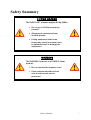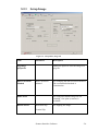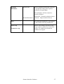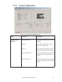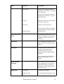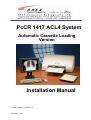
1
PcCR 1417 ACL4 System
Automatic Cassette Loading
Version
Installation Manual
Catalog number: AT095047-01
November, 2004
OREX Ltd. is a market innovator in the field of portable Computed Radiography Technologies—
designed and priced for low-volume clinic or field unit needs.
Founded in 1995 under the name of Digident, the company initially entered the market of desktop
dental radiography providing high quality, portable CR reading units for dental and orthodontic
professionals around the world. The secret of Digident/OREX’s rapid success lies in the best
cost-performance ratio on the market.
OREX designs, manufactures and markets phosphor image laser scanners. These units replace the
traditional x-ray film and light box. The scanners allow the user to immediately read the x-ray
image from the phosphor plate, and transfer it to a DICOM 3 compatible digital computer file.
Once transferred, users can manipulate the digital image for close-up screening, or transmit it for
long-distance consultation. After each scan, the phosphor plates are automatically erased by the
unit, ready for re-use.
OREX provides clients with a full solution including phosphor image plates, laser readers,
software for image processing, storage, retrieval and communication in Picture Archiving and
Communications System (PACS) compatible format.
The company’s mission is to become a leading provider of compact personal CR systems.
Following the successful penetration of the global dental market, the company changed its name
from Digident to OREX and expanded its markets and product lines to serve the dental, medical,
military, industrial and veterinary fields.
“We are committed to assisting our customers in obtaining
maximum value from OREX products by providing excellent
support at exceptional value.”
Technical Support
Israel Headquarters:
Tel: ++972-4-959-1331
Fax: ++972-4-959-1262
E-mail: [email protected]
US Office:
Tel: ++1-617-244-9000
Toll free: 1-888-844-7775 (within
US only)
Fax: ++1-617-244-9020
E-mail: [email protected]
Document Part Number: AT095047-01
Printed in Yokneam, Israel 2002
Copyright © 2002, all rights reserved
Safety Summary
LIFTING HAZARD
U
The PcCR 1417 scanner weights 40 Kg (88lb).
• Do not try to lift the scanner by
yourself.
• Always seek assistance from
another person.
• Lifting equipment that is too
heavy may result in serious injury
to personnel and/or damage to
equipment.
WARNING
U
The PcCR1417 scanner is a CLASS 1 Laser
product.
•
Do not remove the scanner cover
•
Cover removal should be done
only by authorized service
personnel
Safety Summary
i
Laser Safety Instructions
1. During normal operation, to prevent the surronding
area from being exposed to laser, the scanner
should always be enclosed in its protective cover.
This is
2. During normal operation, the cover should not be
removed. Removing the cover should only be done
for service purposes by a qualified technician.
Safety Summary
ii
Table of Contents
1.
Terms and Conventions..............................................................1-1
2.
Packaging.....................................................................................2-1
3.
Site Preparation...........................................................................3-1
3.1
3.2
3.3
3.4
3.5
4.
Installation ...................................................................................4-1
4.1
4.2
4.3
4.4
4.5
5.
General ............................................................................................... 3-1
Computer Requirements..................................................................... 3-1
Space Requirements ........................................................................... 3-1
Electrical Requirements ..................................................................... 3-2
Environmental Requirements............................................................. 3-2
3.5.1
Temperature ........................................................................ 3-2
3.5.2
Light .................................................................................... 3-2
General ............................................................................................... 4-1
On-Site System Configuration ........................................................... 4-2
Equipment Required For Complete Installation................................. 4-3
Installation process............................................................................. 4-4
4.4.1
Connecting the cables.......................................................... 4-4
4.4.2
Installing the drivers for the PcCR 1417............................. 4-4
4.4.3
Installing the “Scanner Interface” ....................................... 4-8
4.4.4
Onyx-Rad Installation ....................................................... 4-16
4.4.5
Licensing the GOP Filters ................................................. 4-17
Installation Report ............................................................................ 4-20
Scanner Interface Software........................................................5-1
5.1
5.2
General ............................................................................................... 5-1
Interface Description .......................................................................... 5-1
Table of Contents
iii
5.2.1
5.2.2
5.2.3
5.2.4
5.2.5
5.2.6
5.2.7
5.2.8
5.2.9
5.2.10
Main Screen......................................................................... 5-1
Setup Anatomical ................................................................ 5-3
Setup Image......................................................................... 5-6
Setup Configuration ............................................................ 5-8
Setup Operation Update .................................................... 5-12
Setup Diagnostics.............................................................. 5-13
Setup Automatic Tests ...................................................... 5-15
Setup Advance................................................................... 5-16
Setup About....................................................................... 5-18
Image Diagnostics ............................................................. 5-20
6.
Troubleshooting ..........................................................................6-1
7.
Appendix A: Installation Prerequisites.....................................7-1
8.
Appendix B: Installation Report ...............................................8-1
Table of Contents
iv
List of Figures
Figure 1: Closed Box...............................................................................................................2-1
Figure 2: Open Box .................................................................................................................2-1
Figure 3: PcCr 1417 Dimensions ............................................................................................3-2
Figure 4: System Configuration ..............................................................................................4-2
Figure 5: Dongle parallel/USB for Onyx-Rad software..........................................................4-2
Figure 6: Dongle Parallel Plug for GOP filter.........................................................................4-3
Figure 7: CVLicense Window Before GOP Licensing.........................................................4-17
Figure 8: Setting the GOP License Key ................................................................................4-18
Figure 9: CVLicense Window After GOP Licensing ...........................................................4-19
Figure 10: Scanner Interface, Main Screen.............................................................................5-1
Figure 11: Setup Menu, Anatomical tab .................................................................................5-3
Figure 12: Setup Menu, Image tab .........................................................................................5-6
Figure 13: Setup Menu, Configuration tab..............................................................................5-8
Figure 14: Setup Menu, Operation Update tab .....................................................................5-12
Figure 15: Setup Menu, Diagnostics tab ...............................................................................5-13
Figure 16: Setup Menu, Automatic Tests tab........................................................................5-15
Figure 17:Setup Menu, Advance tab.....................................................................................5-16
Figure 18: Setup Menu, About tab ........................................................................................5-18
Figure 19: Image Diagnostic screen (Mini Viewer)..............................................................5-20
List of Figures
v
1. Terms and Conventions
The following abbreviations are used throughout this manual:
FSE
Term
Meaning
Field Service Engineer
PSP
Photo-Stimulate Phosphor
USB
Universal Serial Bus
Terms and Conventions
1-1
2. Packaging
The PcCR 1417 is shipped in a custom designed box that protects the
scanner. If the PcCR 1417 needs to be returned to Orex or to one of its
dealers, the scanner must be repacked in its original box, and must include
the CD and the USB cable.
Figure 1: Closed Box
Please use all the protective parts in the box in order to minimum the risk of
damage to the scanner.
Figure 2: Open Box
Packaging
2-1
3. Site Preparation
3.1
General
Inform the client about the site preparation requirements prior to installing
the PcCR 1417. Without these requirements being met, you cannot complete
the installation, and the client’s ability to use the PcCR 1417 properly can
not be guaranteed.
3.2
Computer Requirements
Pentium 4, 1.8 GHz (or above)
256 MB RAM (512MB recommended)
Hard drive – 40 GB (or above)
Network adapter (required for Dicom – send)
Operating system – Win 2000
USB Port
NO USB mouse or keyboard
Parallel port
Screen resolution – 1024 x 768 (or above)
3.3
Space Requirements
The PcCR 1417 shall be positioned on a stable surface, with at least 20 cm
(~ 8”) free space on every side of the scanner. A long USB cable shall
connect the PcCR 1417 scanner to the computer, enabling proper spacing of
these units from each other.
The space requirements for the PcCR 1417 (including scanner dimensions
and additional space) are shown below:
Site Preparation
3-1
50 cm
100 cm
80 cm
Figure
Electrical Requirements
3: PcCr 1417 Dimensions
3.5
Voltage:
90 V–250 V AC
Frequency:
50Hz–60Hz
Fuses:
Two fuses are located next to the On/Off switch at the
back of the scanner. Each fuse protects one of the
power supplies. The fuses are 1A (slow blow).
UPS:
Online; 500 VA
Environmental Requirements
3.5.1
Temperature
Maintain the room temperature between 18ºC and 30ºC, normal
lab conditions; relative humidity 80%, non-condensing.
3.5.2
Light
The PcCR 1417 is sealed and protected from light penetration.
However, it is recommended to keep the PcCR 1417 in standard
room light, away from exposure to direct sunlight.
The PcCR 1417 uses phosphor plates for acquiring images. The
phosphor plates are sensitive to light, and therefore exposure to
light should be kept to a minimum. The phosphor plates should
Site Preparation
3-2
be exposed to light only when they move from the cassette into
the PcCR 1417 scanner.
For optimal results, room light is recommended at less than 1000
Lux.
Site Preparation
3-3
4. Installation
This chapter explains the installation procedure of the PcCR 1417.
The FSE who installs the PcCR 1417 shall follow the steps described herein. Upon
completion of the installation, fill out the Installation Report (Appendix B).
4.1
General
On-site installation of the PcCR 1417 shall be carried out by FSEs authorized by Orex,
and will follow the instructions below:
1. Unpack the PcCR 1417 and position it in the desired location.
2. Verify the integrity of the unit and its components.
3. Plug the system into the electrical outlet, and connect the USB cable to
the PC (section 4.4.1.)
4. Plug in the WIBU-KEY (green dongle) supplied with the Onyx-Rad CD
to the parallel port on the back of the computer, the green dongle must
be the first one connected to the parallel port and then you can connect
other dongles to him!!!
5. Plug in the GOP dongle to the parallel port on the back of the computer
on the Onyx-rad dongle.
6. Install the software for the PcCR 1417 (section 4.4.2 – 4.4.4.)
7. Test the system’s functional operation.
8. Send a completed Installation Report (Appendix B) to Orex service
department.
Note: The warranty shall not be issued until Orex service department receives the
installation report. (Warranty will be issued only after the Orex service department
receives the installation report)
Installation
4-1
4.2
On-Site System Configuration
PC
PC
PC
Server
PC
PC
Onyx-Rad
Scanner
Interface
PACS
GOP
PcCR
1417
Figure 4: System Configuration
PC – Make sure that the PC you are using meets the requirements described in
Section 3.2, Computer Requirements
Scanner interface – Software supplied by Orex with every system
GOP – Enhancements for the scanner interface software for the purpose of image
enhancement (requires special dongle connected to the parallel port of the PC)
Please note:
Installation without the GOP causes a non-optimal image quality.
Onyx-Rad– Imaging software installed on the PC for the purpose of acquiring, storing,
and Dicom sending the images to different stations
Please note:
Users that do not intend to use Onyx-Rad should skip section 4.4.4.
Installation
4-2
4.3
Equipment Required For Complete
Installation
•
PC (refer to “computer requirements” for details)
•
Cables: Power cable (not included with the PcCR 1417), USB cable
(included with the PcCR 1417)
•
“Scanner interface” CD
•
“Onyx-Rad” CD
•
Dongle parallel/USB for licensing Onyx-Rad software (figure 5).
•
Dongle (parallel plug) for licensing GOP filters (figure 6).
Figure 5: Dongle Parallel/USB Plug for Onyx-Rad software
Figure 6: Dongle Parallel Plug for GOP filter
Installation
4-3
4.4
Installation process
The installation process includes the following:
4.4.1 Connecting the cables
4.4.2 Installing drivers for PcCR 1417
4.4.3 Installing “scanner interface”
4.4.4 Installing Onyx-Rad
4.4.5 Installing the Dongle (license for GOP)
4.4.4 Licensing the GOP filters
4.4.1
Connecting the cables
1. Connect the power cable from the PcCR 1417
to the power outlet.
2. Connect the USB cable (included in the PcCR 1417 box)
to the USB port of the PC.
4.4.2
Installing the drivers for the PcCR
1417
1. Turn on the PcCR 1417. The system makes
initializations noise. “Found new hardware”
screen appears, followed by the installation
screen:
2. Click “next”
Installation
4-4
3. Choose “Search for a suitable…”; then click
“Next”
4. Leave only the “specify a location” check-box
selected; then click “Next”
Installation
4-5
5. Insert the “scanner interface” CD in to the CD-Rom drive.
If installation does not begin automatically, Click the “Browse”
button.
6. A “Locate file” window appears.
Browse to the CD-Rom.
7. Double click the “Driver for windows 2000
and XP” folder.
Installation
4-6
8. Mark the “orex02.inf” file; then click “Open”
9. The Installation Wizard finds the driver for the
PcCR 1417.
Click “Next”.
10. Click “Yes” to confirm the driver file
11. The installation wizard completes the
installation of the driver.
Installation
4-7
4.4.3
Installing the “Scanner Interface”
1. Insert the “Scanner Interface” CD into the CDRom drive. If installation does not begin
automatically, Double-click on “My
Computer” and choose the CD-Rom drive. The
content of the CD will appear on a new
window:
2. Double-click the “setup.exe” file.
3. The installation of “Scanner Interface” begins.
Click “Next”.
Installation
4-8
4. Click “Next”.
5. Choose “Install new filters” and click “Next”.
The software installs.
Installation
4-9
6. Choose the option appropriate to the specific
system. Click “Next”.
Installation
4-10
7. Click Next
8. Use the default options and Click “Next”
9. Click “Next”
Installation
4-11
10. When all tasks are completed, click “Next”.
11. Click “Finish”
12. Click “Next”
Installation
4-12
13. Choose “I accept the license …….. “ and then
click “Next”
14. Choose the default option “complete “ and then click “Next”
Installation
4-13
15. Click “Next”
16. Click “Finish”
Installation
4-14
17. Choose “Yes, I want to restart my computer now” and click “OK”
Installation
4-15
4.4.4
Onyx-Rad Installation
The Onyx-Rad software is supplied on a CD separate from the “Scanner
Interface” CD.
For installation of the Onyx-Rad software, refer to the detailed explanations
in the Installation Manual located on the Onyx-Rad CD.
Note:
1. To function, the Onyx-Rad also needs the Dongle, installed in
section 4.4.4. If the Dongle is not installed, or is not connected to
the parallel/USB port, the software cannot run.
2. Restart the computer at the end of the Onyx-Rad installation.
Installation
4-16
4.4.5
Licensing the GOP Filters
This section can be applied ONLY after installing the Dongle. This process
is performed automatically with the scanner interface software installation.
1. Plug the dongle to the parallel port on the back
of the computer.
2. Insert the “Scanner Interface” CD into the CDRom drive.
3. Double click the “CVLicense.exe” file.
Figure 7: CVLicense Window Before GOP Licensing
4. A new window appears. Double click “CVIEOrex-Soft” (5rd line).
Installation
4-17
5. The licensing window appears. Enter the code supplied by Orex into
the “Key” dialog box. If you have not received the code, please contact
your distributor. The code is unique, and depends on the SN of the
Dongle, which appears on the dongle as a 4-digit number at the bottom
line.
SN=00D8 (example)
Figure 8: Setting the GOP License Key
6. Enter the code you received; then click “Set
Key”.
Installation
4-18
Figure 9: CVLicense Window after GOP Licensing
7. The previous screen appears again. This time the “CVIE-Orex-Soft” on
the 5ht row, the message “license is valid” should appear in the status
column. If the status does not change to “license is valid” check the key
that was entered again and confirm that small/big letters were written
correct.
Installation
4-19
4.5
Installation Report
For the warranty of the PcCR 1417 to take effect, and in order to verify correct
installation by Orex, you are required to fill out the installation form and fax/e-mail to
Orex service department.
The installation form is located in Appendix C
Orex Contact Information
Israel:
Fax: (+972) -4- 9591262
Email: [email protected]
USA:
Fax: (+1) -617-244-8888
Email: [email protected]
Installation
4-20
5. Scanner Interface Software
5.1
General
The Scanner Interface Software is a module that enables the FSE to access to the
PcCR 1417 advanced setup, and the user to interface with the system.
Following is a list of screens, and their functionality:
5.2
Interface Description
5.2.1
Main Screen
This screen is used as the interface between the end user and the scanner.
1
2
3
4
5
6
7
Figure 10: Scanner Interface, Main Screen
Title
Description
1. Unit
Click here to select the x-ray unit being used
2. Region
For selecting the anatomical region to which the image to be
scanned, belongs.
3. Scan
Use to initiate the scan. During the scan a pre-view of the
scanned image is displayed. At the end of the scanning process,
the interface window closes
Scanner Interface Software
5-1
Title
Description
4. Erase
For erasing the image on the phosphor plate.
5. Eject
For unloading the plate; then ejecting the cassette.
6. Setup
For entering the Setup interface.
The login screen is displayed:
• User password – None
• Technician password – 9591
• Orex Technician password – Contact Orex Service
Dept.
7. Exit
For exiting the PcCR 1417 interface.
Scanner Interface Software
5-2
5.2.2
Note:
Setup Anatomical
Each setup relates to a specific part, to be scanned from a plate that
originated from a specific x-ray machine.
To enter the Anatomical screen choose the “User” mode and click “OK”.
Figure 11: Setup Menu, Anatomical tab
Title
CR\PORTALS
Parameter
Description
CR – works with standard X-ray settings.
PORTALS- works in RT mode.
Unit Select
The PcCR 1417 can support up to 4
different x-ray units. Each unit has its
own set of parameters.
Select/name the unit on which you want
to work. You can change the unit name at
any time
Scanner Interface Software
5-3
Title
Parameter
Description
Organ
Organ List
Select the required organ from the dropdown list. The following organs are
available:
•
•
•
•
•
•
•
Sub Organ List
Skull
Upper Extremities
Chest
Abdomen
Spine
Lower Extremities
Abdomen
Select the required sub-organ from the
available list; this has to describe the
image you want to scan.
This is an initial list; you can add, and
delete organs to any of the sub-organ lists
(see the two buttons below).
Set new sub-organ
name
Add new SubOrgan
To add a new sub-organ:
• Select the Organ.
• Type the new Sub-organ.
• Click Add.
Delete Sub-Organ
To delete a sub-organ:
• Select Organ.
• Select Sub-organ.
• Click Delete.
Enable the option to apply automatically
a filter for each organ individually.
CV filter
Calibration
Settings
Sub Organ
Acquisition Setup
Pm Gain
For performing Automatic Calibration.
Refer to the Calibration chapter in the
User Manual.
Set PM Gain First
Calibration
Settings
Refer to the Calibration chapter in the
User Manual.
PM Gain
calibration
After performing the automatic
calibration process, it is possible to fine-
Scanner Interface Software
5-4
Title
Parameter
Description
tune the image.
If the image is too dark, increase the
value by 10 numbers.
If the image is too light, decrease the
value by 10 numbers.
Offset
Indicate the current Offset calibration,
(for more details refer to the User
Manual).
Do not change this value.
External Settings
For using settings pre-defined by an
external software application.
Scanner Interface Software
5-5
5.2.3
Setup Image
Figure 12: Setup Menu, Image tab
Title
Parameter
Enable the option to save the image as a
jpeg file.
Jpg image
properties
Data Correction
Method
Data Correction
Method
For changing the data correction method.
The recommended method is
Linearization.
For using an available image file for
scanning, if no plate (cassette) is
available.
Demo Scan
Rotate canvas
Description
Horizontal flip
For flipping the image.
Vertical flip
Scanner Interface Software
5-6
Big Plate
Resolution
Always Ask
Before scanning a small plate, you will
be prompted to choose the required
resolution (Normal/High).
All small plates will be scanned at
normal resolution.
Normal Resolution
Unchecked – Normal resolution always
Checked – High resolution always
Save
For saving the parameters. This HAS to
be done before selecting another tab.
Auto-crop
Allows Auto-Shutter operation on the
image (removes white areas around the
image). For additional information
contact Orex support.
Geometric crop
Scanner Interface Software
5-7
5.2.4
Setup Configuration
Figure 13: Setup Menu, Configuration tab
Title
Parameter
Description
Local Scanner
Settings
Configuration file
Opens the configuration file with
Notepad.
Origin X
X-axis home, where the scanner
begins to scan the plate.
Origin Y
Y-axis home, defines the location
where the plate enters the scanner.
Steps for Plate Enter
Defines the number of steps for the
loader to return the plate into the
cassette.
Steps for Plate Exit
Defines the number of steps for the
loader to extract the plate from the
cassette.
Scanner Interface Software
5-8
Title
Parameter
Description
Erase Factor
Increase this value for a longer
erasing process (When a very high
dose was used).
Decrease this value for a shorter
erasing process (When a very low
dose was used).
Step Size
Number of steps for each complete
turn of the lead screw.
Screw Size
Diameter of the lead screw.
Data Maximum
Preset values used by the software
to obtain the best results for high
density objects.
Auto Erase after
Scan
The default operating mode of the
scanner. The plate is erased, on its
way back into the cassette after
scanning.
Auto Scan
For automatically starting a scan
when you insert a cassette into the
scanner.
Using W0
For using the W0 sensor. When
the plate reaches this sensor
feeding speed of the plate is
lowered to prevent it from being
damaged.
Do not change the default unless
otherwise instructed by Orex
support.
The carrier does not return Home
after scanning, but waits where it
ended in the last scan, and uses
that position as the starting point
for the next scan.
Bi-Directional
Scanning
Diagnostics
Test Image
For using a test image
Diagnostic scan
For performing a Diagnostic scan
Scanner Interface Software
5-9
Title
Parameter
Description
Image Diagnostic
For the calibration process.
Once this option is checked, after
the scanning process, the Image
Diagnostics screen appears, from
which you will be able to choose
the type of required filter.
ACL4/ACL2I
Must be chosen for nominal work.
ACL4/ACL2I test
For Orex internal use only.
Auto Load
For Orex internal use only.
Origin Settings
For fine-tuning the origin of the
image.
After a scan is acquired, center the
image, by either clicking it to the
required position (or Fine-tuning
for adjusting by smaller steps).
Find Origin after Scan
After scanning, when the image is
displayed, right-click the
top/bottom of the image, or click
the left/right, to align the image
with the scanner Home.
Reset
Resets all values (new Home
values)
Save
For saving the parameters. This
HAS to be done before selecting
another tab.
Roller cleaning
To clean the Scanner rollers,
For more details refer to the User
Manual.
Enable import/export ROW
images to the archive located on:
C:\program
Show restore
button
Scanner Interface Software
5-10
Title
Parameter
Description
files\orex\ACL4SB\archive
Option for technicians to disable
the lamp worming up process
Warming up
override
Scanner Interface Software
5-11
5.2.5
Setup Operation Update
Figure 14: Setup Menu, Operation Update tab
Title
Parameter
Use to select the desired unit for
performing backup, or restoring
Unit 1-4 Backup
Configuration
Backup
Update Main
Firmware
Description
A. PC Backup
Backup of data to a PC.
B. Memory backup
Backup of data to serial EPROM
Software Update
Click the Software update button to
update the software to the scanner.
Boot Password
Displays the Boot password.
Scanner Interface Software
5-12
5.2.6
Setup Diagnostics
Figure 15: Setup Menu, Diagnostics tab
Title
Parameter
Description
Optical
Erase Lamp
Turn on/off the Erase lamp
Lamp1
Indicates that lamp1 is on.
Lamp2
Indicates that lamp2 is on.
Laser
Turns on/off the Laser unit
On
Turns on the Rotational motor
Speed
Indicates the speed of the rotational
motor.
Rotational Motor
Stepper Motor
End
Start
Each click moves the carrier in the
selected direction. When the carrier
approaches its travel limit, it activates a
limit switch (red indicator).
Scanner Interface Software
5-13
Title
Parameter
Description
Plate Control
Sensors
Sensors
Cassette in place – Cassette is docked
Cassette hold – Cassette is locked
Loader back– Loader has reached plate
W0 – Plate is approaching rollers; has to
slow down
Roller – Feeding rollers
Z0-Z4 – Positioning sensors
Moves the plate In or Out of the scanner.
In
Out
High/Low slide-bar Controls the movement speed of the plate
in the scanner.
Loader Control
Unload
Unloads the cassette
Reset
Resets all the sensors and motors in the
Diagnostic menu.
Plate Status
Displays the status of the plate
Loader Status
Displays the status of the plate loader
Forward
Moves the Loader forward
Back High
Back Low
Custom – Steps
Moves the Loader into the cassette. Each
click moves it the number of steps typed
into Steps.
Scanner Interface Software
5-14
5.2.7
Setup Automatic Tests
This menu is used primarily, at the end of the Orex production line, for burn-in tests.
Figure 16: Setup Menu, Automatic Tests tab
Title
Parameter
Description
Scanner Test
Test Counter
Displays the number of tests that have
been run.
Displays the test results.
Display Test Result
Test Settings
Automatic Scan
Performs a scan automatically, when the
cassette is inserted into its port. This test
is usually run with the Automatic
Load/Unload test
Automatic Erase
Performs an automatic erase.
Automatic
Load/Unload
Automatically Loads and unloads the
plate. This test is usually run with the
Automatic Scan test.
Number of tests
Sets the number of tests to run.
Scanner Interface Software
5-15
5.2.8
Setup Advance
Figure 17: Setup Menu, Advance tab
Title
Parameter
Description
Scanner ID
Serial Number
From here you can edit the serial number,
and the DV number.
Displays the serial number of the system.
DV Number
Scan mode
Scan Counter
Displays the number of scans performed.
Reset
Resets the number of scans to “0”.
Single mode
One image at a time is saved after scan
process is finished to the database.
Multi image scan
Interface Settings
Scan several images before transferring
them to the database.
RAIS2
Dual scan mode – two scanners
connected to the same computer
Anatomical
Interface
Check for the body image on the main
screen.
Uncheck for test-labeled buttons. The
labels can be renamed by using the Orex
Editor.
Scanner Interface Software
5-16
Title
Save
Parameter
Description
For saving the parameters. This HAS to
be done before selecting another tab.
Scanner Interface Software
5-17
5.2.9
Setup About
Figure 18: Setup Menu, About tab
Title
Parameter
Description
Software Version
1. Motion
Currently used version of the Motion
board
1.1 USB (FPGA)
Currently used version of the USB
(FPGA).
2. Firmware (boot)
Currently used version of the Firmware
(boot)
3. Firmware
(Motion)
Currently used version of the Firmware
(Motion)
4. Driver
Currently used version of the Driver
5. Scanner
Interface
Currently used version of the Scanner
Interface
Anatomical
database
Currently used version of the Anatomical
database
Scanner Interface Software
5-18
Title
Parameter
Description
Scanner ID
Serial number
Scanner serial number
Scan counter
Number of scans been done
Scanner Interface Software
5-19
5.2.10 Image Diagnostics
For performing final calibration of the filters assigned to the displayed part (suborgan), after scanning the desired image is displayed on the mini viewer.
The results can be seen immediately, as opposed to the Setup screens where the results
are not immediately visible.
Figure 19: Image Diagnostic screen (Mini Viewer)
Title
Parameter
Description
Organ Selection
Organ
For selecting the main classification
(organ)
Sub Organ
For selecting the actual (viewed)
sub-organ
Image Adjustments Filters
Use to select the filter.
Scanner Interface Software
5-20
Title
Parameter
Description
Data Correction
method
For changing the data correction method.
The recommended method is
Linearization.
For changing the Data Minimum.
Data minimum
Process
For viewing the result of the new setup
Reset
For resetting the image
N.R
Noise reduction
Auto shutter
Eliminate white borders around the
image.
Gain factor
This parameter moves the histogram to
the desired location on the graph and sets
the new PM gain value in the Anatom.ini
file.
Histogram
To view the histogram of the displayed
image
Save
To save the settings.
Exit
To exit the mini-viewer.
5.2.10.1
Using the Image Diagnostics Functions
1. Select the correct Sub-organ from the relevant Organ.
2. Select the desired Filter; then click Process to view the filtered image.
3. You can now right-click and drag to change contrast and intensity; or
click and drag to change zoom. The cursor changes accordingly.
Alternatively, you can use the sliders at the bottom right of the screen.
4. If the result is not satisfactory, you can click Reset to reset the image;
then repeat the procedure with another filter, until you get the best
image.
5. When the desired image quality is attained, click Save. Whenever this
part is selected for scanning under this unit, the image will be filtered at
this saved quality.
Scanner Interface Software
5-21
It is possible to view the histogram of the image.
In addition, for each sub-organ you can set a Data Minimum value.
Scanner Interface Software
5-22
6. Troubleshooting
Problem
“Disconnect” error
message appears on the
“scanner interface”
screen
Onyx-Rad software
does not load. Error
message received
GOP filters do not
apply on the image
What should I do?
1. Check:
Power cable connected?
USB cable connected?
2. Turn system off; then on again.
Check if Dongle is connected to the
parallel port of the PC
See also: Chapter 4:
Installation
Make sure that the GOP filters are
licensed
See also: Chapter 4:
Installation
After the system is
turned on, initialization
sound does not stop.
Cassette cannot be
inserted into the tray.
Turn system off; then on again.
If the problem persists, contact your
distributor.
Make sure the cassette is positioned at the
center of the tray.
6.
Image is too bright.
7.
Image is too dark
8.
Double image received
9.
White lines appear on
image.
From the Scanner Interface – Setup menu,
increase “PM-Gain” for the type of image
which is too bright
From the Scanner Interface – Setup menu,
and decrease “PM-Gain” for the type of
image which is too light
1. Check that the erase lamps are
working
2. If the erase lamps are OK, increase
the erasing factor by 5 from the
Scanner Interface – Setup menu Î
Configuration
Contact Orex service department
1.
2.
3.
4.
5.
10. Horizontal lines appear
on image
Contact Orex service department
11. Scan does not start
Contact Orex service department
12. Systems is shaking
Place system on steady surface
13. Diagonal lines appear
on image
There is light penetration into the system.
Place the system away from intense light
source (window).
Troubleshooting
Remarks
See also: User Manual –
Chapter: Using the
scanner interface
See also: User Manual –
Chapter: Using the
scanner interface
See also Chapter 3: Site
Preparation
6-1
7. Appendix A: Installation
Prerequisites
PRE-INSTALLATION FORM
Computer requirements:
PC:
CPU – Pentium 4, 1.8GHz (min.)
RAM – 256MB
Hard-Drive – 40GB
Operating System:
Windows 2000
Monitor:
Size – 17” (min.)
Resolution – 1024x768 (min.)
Ports:
USB port available
NO USB mouse or keyboard
Parallel port
Additional:
Network adapter (for Dicom send)
.1
Space requirements
Stable surface
Width – 100 cm
Height – 50 cm
Depth – 80 cm
Electrical requirements:
Voltage – 90-250 VAC
Frequency – 50-60 Hz
UPS – Online, 500 VA
UPS connected to CR system, PC,
Monitor
.2
Environmental requirements
Temperature – 18ºC-30ºC normal lab
conditions
Humidity – 80% non condensing
Light – less than 1000 Lux
Configuration requirements:
Name off PACS on the site *
Dicom send required?
Dicom Print required?
Yes / No
Yes / No
Appendix A: Installation Prerequisites
7-1
Single Media Archive required?
•
Yes / No
When using the PcCr 1417 with a main PACS on site, the images are Dicom sent to the
PACS. Please verify with Orex the compatibility of the PACS to Orex software.
Appendix A: Installation Prerequisites
7-2
8. Appendix B: Installation Report
INSTALLATION REPORT
Reporting distributor:
Company name:
Technician installing the PcCr 1417:
Name:
Tee. No.:
e-mail:
Site information:
Name:
Address:
Tel. No.:
Additional information:
Installation pre-requisites:
Date:
SN of system installed
Computer requirements met ?
Space requirements met ?
Electrical requirements met ?
Environmental requirements met ?
* See Installation pre-requisites, Appendix B
Installation process
Drivers for CR
Scanner interface
Or-Acquire
GOP drivers **
GOP licensing **
** Optional
Accessories (PLEASE SPECIFY QTY.)
14x17 cassettes
14x14 cassettes
10x12 cassettes
8x10 cassettes
Onyx-Rad
Dicom send ***
Dicom print
SNA
*** Please specify name of PACS to which the images are sent
Name: __________________
Signature: __________________
Appendix B: Installation Report
8-1