1
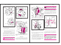
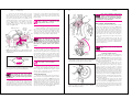
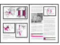
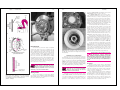
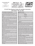
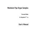
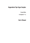
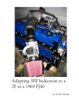
This sample chapter is for review purposes only. Copyright © The Goodheart-Willcox Co., Inc. All rights reserved.
210
Chapter
13
Disc Brake
Service
After
K
K
K
K
K
K
studying this chapter, you will be able to:
Identify common disc brake problems.
Diagnose disc brake problems.
Remove and replace front disc brake calipers.
Remove and replace rear disc brake calipers.
Remove and replace disc brake pads.
Refinish disc brake rotors.
Auto Brakes
In Chapter 6, you studied the service of disc brake caliper
hydraulic systems. In this chapter, you will learn how to diagnose and service the disc brake system friction components.
Pad and rotor service is very similar for every kind of disc brake
system, varying only according to size, mounting method, and
whether the caliper has a provision for a parking brake.
Variations, where they occur, will be noted in the text.
Common Disc Brake Problems
The most common disc brake problems are noise and
pulsation. Common brake noise includes squeaks and
squeals from brake shoe and rotor contact. Disc brakes
commonly produce high pitched squeals or squeaks when
the brakes are applied. This is often caused by glazed or
worn pads, but may be the result of polished (overly
smooth) rotors, excessively hard pad material, or the wear
indicator contacting the rotor. A grinding or rubbing noise
when the brakes are applied may indicate the pad linings
are worn and the metal shoes are contacting the rotor. Clicks
and knocks are produced by loose pad-to-caliper contact.
Pulsation is a type of vibration. It is usually felt as a sideto-side motion in the steering wheel, or an up-and-down
motion in the brake pedal, or both, when the brakes are
applied. Pulsation is usually caused by variations in the rotor’s
surface. Long use or excessive heat can cause the rotor to
develop thickness variations, high spots, or warping.
Pulsation is also caused by hard spots (places in the rotor
which have become overheated and lost their original finish).
If heavier than normal pedal pressure is needed for
braking, this may be caused by worn or excessively hard
brake pads. Another cause of a hard pedal is an overheated brake system. Overheated rotors and pads have a
poor coefficient of friction, meaning the pedal must be
applied much harder to have the same braking effect.
However, before assuming the cause of a hard pedal is the
disc brakes, check the brake hydraulic system and any
power assist units.
A spongy pedal can be caused by caliper and mounting hardware flexing. This is usually not a problem unless
the vehicle is designed to operate with high hydraulic system pressures. Extreme caliper or bracket wear, cracks at
the mounting points, or loose bolts can also cause a
spongy pedal.
Rear disc brake defects include all of those previously
mentioned, plus specific problems involving the parking brake.
Sticking pistons or cables are the usual cause of problems. The
parking brake can stick in the applied or released position.
Pads and rotors that wear out ahead of time are often
caused by driver habits, or severe usage, such as mountain
driving or trailer towing. If the pads are wearing unevenly,
check for a sticking piston or slide pins, misaligned caliper,
or flexing. Figure 13-1 lists common disc brake problems
and their causes.
Caliper and Pad Service
While calipers and brake pads are similar in basic
components and operation, there are many differences in
design. These differences are in the areas of mounting,
noise reduction clips and insulators, and fasteners. These
are addressed where applicable.
Disc Brake Problems (All)
Condition
Important Terms
Noise
Grooving
Possible Causes
High-pitch squeal only when brakes applied
Glazed linings or polished rotor.
High-pitch squeal only when brakes released
Pad wear sensor contacting rotor, replace pads.
High-pitch squeal at all times
Splash shield contacting rotor.
Silencer band
Hot spots
Metallic grinding when brakes applied
Pads worn down to metal.
Sticking caliper.
One pad worn more than the other
Caliper piston or slides sticking.
Caliper misaligned.
Brake pedal pulsates
Excessive rotor runout.
Normal ABS operation.
Excessive pedal effort
Glazed linings. If linings OK, problem is in power
booster system.
Pulsation
Heat-checking
Rough cut
Swirl grinding
Loaded calipers
Bluing
Finish cut
Non-directional finish
Staking
Arbor
Oscillating
Bedding-in
Scoring
Rotor adapters
Rear Disc Brake Problems
Vehicle rolls with parking brake applied
Rear caliper pistions sticking.
Parking brake cable misadjusted.
Vehicle rolls when in gear with parking applied
If resistance felt when moving, rear brakes OK.
If resistance is not felt, rear caliper pistons sticking or
parking brake cable misadjusted.
Figure 13-1. Troubleshooting chart listing problems that can occur with disc brakes.
209
Chapter 13
Disc Brake Service
211
Performing Disc Brake Service on
ABS/TCS Equipped Vehicles
Many of the most common brake service procedures,
such as pad replacement, rotor service, and wheel bearing
replacement, are not affected by the presence of anti-lock
brakes (ABS) or traction controls (TCS). If the lining or friction
service replacement procedures involve the wheel speed
sensors, treat them gently, and recheck the gap where applicable. Do not drop or hammer on the sensor rings, or use
them to pry on other components. Do not replace any system
hoses with standard (non-ABS) hoses. The higher pressures in
these systems can rupture a standard brake hose.
Checking Caliper and Pad Condition
Calipers are usually trouble free. However, they can
occasionally develop external brake fluid leaks or sticking
apply pistons. Hydraulic system problems were discussed
in Chapter 6. If there are no hydraulic system defects, the
caliper is usually not a source of problems. However, the
caliper should be checked for wear, cracks (especially at
the mounting points), and torn dust boots.
Observing the pad thickness and rotor condition is
the quickest way to determine whether the pads should be
replaced. Uneven wear between the inboard and outboard
pads is a sign of a sticking caliper piston or slide. Uneven
wear on one or both pads indicates that the caliper is misaligned with the rotor.
Note in Figure 13-2 that pad thickness can be visually
checked by observing the pad lining thickness through
openings in the caliper. However, this provides only a general idea of pad thickness. If the pads have a wear sensor,
you can check the amount of clearance between the sensor and the rotor. If there is any doubt as to pad condition,
remove the caliper and check by measuring the pads
against specified minimum thickness. Note the condition
of the rotor. If the rotor is scored or appears to have been
overheated, the pads need replacement. Also, make sure
the wheel turns freely. If the wheel will not turn easily, the
caliper piston may be sticking, or there may be a problem
with the wheel bearings.
Front Caliper Removal and Pad
Replacement
To remove the caliper, first raise and support the vehicle in a safe manner. If a lift is not available, support the
vehicle at the frame with jackstands. Mark the wheel stud
closest to the tire valve stem with crayon to ensure the tire
is reinstalled in the same position. Then remove the tire
and rim.
Warning: Before proceeding, carefully check
the temperature of the hub and rotor
assembly. If the assembly feels hot, allow it
to cool, or use gloves to protect yourself from burns.
Rotor
Figure 13-2. Brake pad thickness can be checked on this
assembly by looking through the inspection hole in the caliper.
(Toyota)
Caliper
Suspension
strut
Allen head
mounting bolt
Inboard shoe
and pad
Ratchet
wrench
Rotor
Piston
Brake line
Adjustable
pliers
A
Bracket
If the pads are going to be replaced and no other
service is needed, it is not necessary to remove the caliper
hose. If the caliper uses an electrical pad wear sensor, disconnect the sensor electrical connector, Figure 13-3.
Torx®
socket
Figure 13-4. Using pliers to lightly force the inboard pad and
piston away from the rotor. This allows for easier caliper
removal. (Pontiac)
Pad sensor
plug
Pin
Pad
Caution: If the pads will be reused, do not
damage them by prying. It is usually possible to pry on the metal shoe portion of the
pads to move them. On some calipers, the pads can
be loosened by pushing the caliper housing forward
with a large C-clamp.
Pin
Pad
Shoe
Auto Brakes
Note: The following procedure is for
replacing the pads without overhauling the
caliper. If the caliper must be overhauled,
refer to Chapter 6.
Figure 13-3. A disc brake assembly which uses electric pad
wear sensors. (Land Rover)
Inspection hole
212
Use a small prybar, C-clamp, large adjustable pliers,
or other tool to lightly push the pads away from the rotor,
Figure 13-4. This will make caliper removal easier. If the
rotors and pads are badly grooved, the pads may need to
be moved back a considerable distance before they can be
removed.
On vehicles equipped with ABS systems, some manufacturers recommend opening the bleeder screw to allow
fluid to escape, rather than pushing it back into the
hydraulic actuator and master cylinder. This minimizes the
chance of contamination, which could cause problems.
Check the service manual before proceeding.
Remove the fasteners holding the caliper to the spindle. There are several methods of attaching the caliper to
the spindle:
K On some vehicles, the caliper is held by bolts which
thread into the caliper and slide on the spindle
through steel sleeves or bushings, Figure 13-5. These
bolts can be standard capscrews, or may have round
heads with an internal Allen or Torx® fitting.
K Other brake systems use bolts which thread onto the
spindle assembly. The caliper slides on these bolts
through hardened steel sleeves and/or bushings. See
Figure 13-6.
K On some vehicles, the caliper is held in place by rubber or metal clips or bushings. The bushings, also
called support keys, are in turn held by screws or
bolts, Figure 13-7. The fasteners can be removed and
the clips or bushings lightly tapped out to remove the
caliper. The fasteners shown in Figure 13-8 are
removed and the clips are lifted off to free the caliper.
Torx® head
mounting
bolts
B
Figure 13-5. A—This illustrates Allen head mounting bolts
used on a brake caliper. B—Torx ® head bolts and the bit
needed for removal and installation. (General Motors)
Caliper guide
pin bolt
Figure 13-6. A brake caliper that uses caliper guide pin bolts
that, when installed, thread into the spindle.
Chapter 13
Disc Brake Service
Outboard pad
and plate
213
Caliper
housing
Retainer
clip
214
Auto Brakes
Rotor
Anti-rattle
spring
Anchor plate
machined
"ways"
Shoes and
lining (pads)
Note: The caliper components must
not be exposed to any petroleum based
lubricants. Use silicone compounds and
brake fluid for lubrication, and only where specified.
Caliper
machined "ways"
Installing New Pads on the Front Calipers
Retaining
screw
Caliper
Inboard pad
flange
Caliper
support
key
Rotor
A
Splash shield
Anchor
plate
Anchor plate
machined
"ways"
Retaining
bolt
Outboard
pad flange
Caliper
machined "ways"
Figure 13-8. This caliper can be freed from the anchor plate by
removing the retainer clips. (FMC)
Caliper
Before installing the new pads, loosen the bleeder
screw and use a large C-clamp to push the caliper piston
into its bore. This is shown in Figure 13-12. Place the old
inner pad, a metal bar, or a block of wood on the piston
surface. This will minimize the chance of piston damage
from the C-clamp. Place a pan under the caliper to catch
brake fluid from the bleeder.
Figure 13-10. A caliper assembly being removed. Note the
pads have come off with the caliper. (DaimlerChrysler)
Caliper
housing
Pistons
Caliper
support wire
C-clamp
Brake
hose
Rotor
Wire
hook
Rotor
Hammer
B
Strut
Drift
punch
Caliper
Caliper support key
Metal bar
Figure 13-7. A—Caliper which is held in place with a caliper
support key and retaining screw. B—After the retaining screw
has been removed, the support key is driven from its slot with
a punch and hammer. (Bendix)
K On a few vehicles, an adapter bracket must be
removed before the caliper can be removed. On other
vehicles, the caliper and bracket can be easily
removed as a unit, and separated later.
After the caliper fasteners are removed, lift the
caliper from the rotor. In some cases, it may be necessary
to twist the caliper slightly for removal. On some systems,
the pads will remain with the rotor, Figure 13-9, while on
others, the pads will come away from the rotor with the
caliper assembly, Figure 13-10. If the caliper will not
be overhauled, use a piece of wire to attach it to the
vehicle.
Caution: Do not allow the caliper to hang by
the hydraulic hose. Hose damage may
result. Use a wire hook, Figure 13-11.
Caliper
Figure 13-12. Using a C-clamp and a metal bar to force the
caliper pistons back into their bores. This will provide the
necessary pad-to-rotor clearance when reinstalling the caliper.
(Pontiac)
Drive axle
assembly
Figure 13-11. Always support the caliper with a wire hook.
Never let it hang by the brake hose. Hose damage may result.
(Chevrolet)
Inner pad
Caliper
bolt
Outer pad
Anchor
Figure 13-9. Caliper assembly being removed. Note that the
brake pads have remained with the rotor and anchor unit.
(Sterling)
Pad Removal
Remove the pads from the caliper, or from around the
rotor as necessary. Some calipers have outer pads that are
held by clips or have been clinched (metal tabs on the
outer pad shoe clamped by force against the caliper). In
these cases, the outer pads must be pried to release them
from the caliper. Most pads will come off easily after the
caliper is removed from the rotor.
If necessary, check the pad thickness with a micrometer or caliper, and compare against service manual specifications. In most cases, however, the pads are obviously
worn enough to require replacement.
With the pads out of the way, carefully check the
caliper for damage or leaking. Also check the rotor as
explained later in this chapter. If the caliper shows any signs
of leakage or damage, it should be overhauled or replaced.
Many technicians prefer to install loaded calipers, which are
new calipers with the pads already installed.
As soon as the piston is seated, stop turning the
C-clamp and tighten the bleeder screw. Continuing to turn
the C-clamp after the piston is seated may damage the
caliper. After the bleeder screw is tight, remove the
C-clamp.
Caution: While it is often possible to push
the calipers back into their bores without
loosening the bleeder screw, this may cause
damage to the master cylinder seals. It can also push
dirt and any debris into and through the hydraulic
actuator on ABS/TCS equipped vehicles. If this dirt
becomes trapped in the valves, it can cause the
hydraulic actuator to malfunction.
Chapter 13
Disc Brake Service
215
Compare the new pads with the old ones to ensure
they are correct. Be sure to note whether the mounting
surfaces (metal shoe) portion is correct, and the linings are
not too thick to prevent the caliper from fitting over the
rotor. After ensuring the pads are correct, install any clips
and anti-squeal insulators on the new pads. If the vehicle
has a separate pad wear sensor, install it in the proper
position, Figure 13-13. If desired, place anti-squeal
compound on the pad shoes where they contact the
caliper. See Figure 13-14.
Audible wear sensor
Outboard
brake pad
assembly
216
bearing grease, or chassis lubricant. The high temperatures
of the brake system will cause it to burn off almost immediately, leaving a sticky residue which will interfere with
brake operation.
Caliper
Rotor
Caution: Do not allow non-graphite antisqueal compounds or lubricants to touch
the pad friction surfaces or rotor.
Caliper Reinstallation
Caliper reinstallation is relatively simple, but must be
done correctly if the brakes are to operate properly. Install
the rotor if it was removed. Before reinstalling the caliper,
check the spindle assembly, splash shield, and other
related parts for damage. Place high temperature lube on
any sliding surfaces of the spindle or adapter bracket.
Pads
New
pads
A
Piston
Caliper
bolt
Anti-squeal
compound
Figure 13-14. Two different styles of brake pad shoes showing
the correct placement of anti-squeal compound. Do not allow
this compound to touch the friction material. (Bendix)
Note: Some technicians prefer to slightly
bevel (grind) the edges of the pads to
reduce the likelihood of brake squealing.
Some newer pads come with beveled edges from the
manufacturer.
Place high temperature lubricant on the parts of the
caliper that move in relation to the spindle assembly.
Typical lubrication points would be the sliding surfaces of
the caliper and spindle, guide pins, sleeves and bushings,
and any related moving parts. Do not use motor oil, wheel
Rear disc brakes with the parking brake assembly
built in require slightly different procedures, Figure 13-17.
In some cases, special tools are needed to retract the
piston into the bore. When servicing pads and rotors on
a rear disc brake assembly, the first step is to disconnect
the parking brake cable from the caliper. Once the parking brake cable is disconnected, loosen the caliper bolts
and carefully remove the caliper. You may need to
remove other components before caliper removal can be
performed.
Three common parking brakes are used with rear
wheel disc brakes. They are the screw, ball and ramp, and
cam. Special procedures for each type is discussed in the
following paragraphs. See Chapter 6 for additional information on caliper service.
Note: Always service one rear caliper at a
time.
Brake
caliper
Figure 13-13. Installing one type of outboard brake shoe and
lining. Note the retaining clip and audible wear sensor position.
(DaimlerChrysler)
Note: Some technicians stake pads by
wedging a small chisel between the bottom
edge of the outer pad and the hub, then
staking the pad using a second chisel and hammer.
This practice is not recommended.
Rear Caliper and Pad Removal
Note: If the calipers were removed from the
vehicle, be careful not to switch calipers
between the left and right sides of the
vehicle. On many vehicles, reversing the calipers will
place the bleeder screws in a position that makes it
impossible to completely remove all air from the
caliper.
Retaining
clip
Auto Brakes
Place the caliper over the rotor, Figure 13-15. If the
caliper does not slide easily over the rotor, do not force it
into place. Remove it and check to see if the piston is fully
retracted and the pads are correct. Some vehicles require
that one end of the caliper be installed first. On other vehicles, the caliper must enter straight into the mounting
bracket. After the caliper is in position, install the attaching
hardware and the brake hose if necessary.
Caution: Start all fasteners by hand before
using a hand or air tool to tighten.
After the fasteners are tight, ensure the rotor can turn
freely with the caliper installed. While turning the rotor, listen for scraping noises that indicate the caliper or another
stationary part is contacting the rotor. Bleed the brakes if
necessary, then reinstall the tire and rim.
Staking the Brake Pads
Some brake caliper designs require the technician to
pinch a portion of the outer pad shoe against the caliper.
This is referred to as clinching or staking the brake pads.
Staking must be performed to prevent the outer pad from
moving. This procedure is done using a large pair of
adjustable pliers (channel lock) or a hammer. Have an
assistant pump the brake pedal to bring the pads against
the rotor. Then, while the assistant presses the brake pedal,
stake the outer pads to the caliper, Figure 13-16.
Caliper
support
Rotor
New pads
B
Figure 13-15. A—Placing the caliper over the rotor. B—Caliper
is being installed over pads and rotor after one side (end) has
been attached to the caliper support. (Chevrolet, Honda)
Caliper
Adjustable
pliers
Figure 13-16. Some brake pads require that metal tabs on the
pad shoe be staked to the caliper. Use a pair of adjustable
pliers to stake the pads. (Chevrolet)
Screw-Type Caliper Service
On disc brake calipers with screw type parking brake
mechanisms, the cable actuating lever is connected to an
actuating or high lead screw. The screw passes through a
splined nut cast in the piston. When the cable moves the
lever, the screw rotates and moves the piston outward,
tightening the pads against the disc.
When servicing this type of caliper, there are two
ways to compress the piston in the caliper. The first is to
turn the piston back into the caliper using a spanner
wrench or special tool once the caliper is removed,
Figure 13-18. The second method allows you to push the
piston back in, similar to front calipers. The first step is to
remove the parking brake actuator lever from the caliper
after the cable has been removed. Do not turn the caliper
high lead screw. Once this lever has been removed, compressing the piston in is much easier, Figure 13-19. Once
the pads are removed, carefully push the piston back into
the caliper. The piston can usually be pushed into the
caliper without damage.
When installing the pads, make sure the “D” shaped
locator lines up with the “D” shaped projection on the
back of the inner brake pad, Figure 13-20. The two-way
check valve should also be replaced whenever the caliper
is serviced. If the actuating lever was removed, replace the
lever seal and make sure the high lead screw is all the way
out after caliper installation.
Chapter 13
Disc Brake Service
217
218
Auto Brakes
Rotor
Splash
shield
Caliper
housing
Sensor
wire
Pad sensor
electrical
connector
Lever
seal
Piston
Lever
Nut
Antifriction
washer
Bench
vise
Spanner
wrench
Return
spring
Shoe tab
"D" shaped
locator
Parking
brake cable
Caliper
housing
Bolt
Apply
lever
Pad
Caliper
A
Caliper
mounting
bolt
Parking
brake
assembly
Shoe tab
Figure 13-18. A spanner wrench is sometimes needed to turn
screw-type rear caliper pistons into the body. (Bendix)
back into the caliper using the special tool to bottom the
piston in the caliper bore. There is no way to bottom the
piston without using this tool.
Cam-Type Caliper Service
The cam-type caliper is a simple design in which an
eccentric cam moves a rod. The rod pushes the piston
and pads into contact with the rotor. The rod is threaded
and mates with an adjusting nut in the piston. The rod and
adjusting nut remove any slack caused by pad wear. To
retract the piston when new pads are installed, the piston
should be turned clockwise as shown in Figure 13-22.
B
A
Figure 13-19. A—Parking brake lever removal can allow a screw caliper’s piston to be pressed in. B—Pressing the caliper piston in
with two pairs of adjustable pliers. (General Motors)
Shoe
Caliper
piston
caliper piston area with a ball peen hammer. Be careful not
to damage the bleed screw. If the piston continues to stick,
remove the caliper and perform an overhaul.
Cutout
Rotor Service
Rear Caliper Reinstallation
Rear caliper reinstallation is the reverse of installation.
If it was removed, reinstall the rotor. Place the new pads in
the caliper or on the rotor assembly. Reinstall the caliper and
reconnect the parking brake linkage if it was removed. If the
vehicle uses an electrical wear sensor, attach the electrical
connector. If needed, bleed the system. If the vehicle has a
drum-in-disc system, be sure to adjust the parking brake. Be
sure to stake the pads if necessary.
B
Figure 13-17. A—A rear wheel disc brake assembly, with the
parking brake cable and hook disconnected from the caliper
apply lever. B—A screw-type rear disc caliper assembly.
Remove the parking brake cable and lever to push in the piston.
(Chevrolet)
Ball-and-Ramp Caliper Service
The ball-and-ramp caliper assembly works by using
three steel balls along matching tapered ramps to apply the
brake pads. To replace the pads without disassembling the
caliper, a special tool, Figure 13-21, must be used to turn
the piston into the caliper bore. Carefully push the piston
Adjusting Rear Disc Brake Calipers
After rear disc brake service, you may need to adjust
the caliper pistons to the rotors. In some cases, the brake
pedal only needs to be pumped several times to bring the
pads in adjustment. However, a special adjustment procedure is sometimes needed to bring the pads into position
and to obtain a good pedal.
Using a flat-head screwdriver, carefully position the
tip against the top lip of the caliper piston, Figure 13-23.
Clamp a pair of vice grips on the caliper’s parking brake
actuating mechanism.
Pad
Tab
Rotate
Caliper
Figure 13-20. This particular brake caliper setup requires the
tab on the brake shoe to be placed in one of four caliper piston
cutouts (slots). (Nissan)
Note: In some cases, this is easier to
perform using a box-end wrench.
While carefully prying against the piston, use the vice
grips to apply and release the parking brake. The caliper
piston should adjust the pads until they just rest against the
rotor. If the caliper piston fails to move, try tapping the
The following sections discuss the service of disc
brake rotors. The condition of the rotor is as important as
pad condition. Many common disc brake problems, such
as noises and pulsation, are caused by the rotor. Therefore,
it is very important that you carefully check the rotors
when the pads are replaced.
Sometimes the rotor is not refinished when the pads
are replaced. However, the usual procedure in most shops
is to refinish the rotor to allow it to wear into the new disc
pads. Whether it is refinished or not, the rotor should be
checked as explained in the following paragraphs.
Caution: Some manufacturers recommend
that rotors be refinished only if they are
scored or out-of-round, which would produce a pulsation. In some cases, extensive driving is
required after refinishing to burnish the pads properly. Some rotors cannot be machined and must be
replaced if they are scored or out-of-round.
Chapter 13
Disc Brake Service
219
Auto Brakes
Visually inspect the rotor for scoring or grooving on
the braking surface, Figure 13-24. Scoring and grooving
are deep cuts in the rotor surface. They always follow the
rotor’s curve of rotation. If the pads have worn to the rivets
or the metal shoe surface, the rotor will be badly scored.
Sometimes, a rotor will be lightly scored by long usage,
especially in sandy or dusty areas. Do not assume the
inboard rotor surface is good if the outboard surface shows
no damage. Scoring can exist on one or both braking surfaces of the same rotor. Machining (turning) the surfaces is
required if the rotor shows any scoring or grooves.
Drive
axle
Caliper
220
Rotate clockwise
to bottom piston
Groove in
rotor surface
Wrench
Special
tool
Turn this direction
to seat tool
against piston
Alignment notch
A
Heat
checking
Bluing (heat
discoloration)
Braking
surface
Figure 13-25. This illustrates heat-checking and bluing caused
by heavy braking, severe service, etc. A heat-checked rotor
should be replaced. (EIS)
Cone
Check
valve
Rotor
Boot
B
Figure 13-21. A—Installing new brake pads on ball and ramp calipers requires the piston be screwed back into its bore. A special
tool is needed for this procedure. Position the tool and rotate the handle counterclockwise while holding the shaft. Continue until the
tool is seated against the piston. Loosen the tool handle about one-quarter of a turn. Now hold the tool handle and turn the shaft
until the piston is completely bottomed. Even though the inward travel of the piston has stopped, it will continue to rotate after bottoming. B—Make sure the tabs on the pad are installed in the alignment notches in the piston. (Wagner)
Locknut
wrench
Piston
boot
Rotor
Lining
Pad
Screwdriver
Screwdriver
Piston
Boot
groove
Caliper
Boot
Piston
Extension
bar
Figure 13-22. Retracting the piston by turning in a clockwise
direction with a special locknut wrench. This will provide the
necessary clearance for installing the new brake pads. (Honda)
Excessive brake heat can cause heat-checking (tiny
surface cracks) or bluing. There can be a combination of
heat-checking and bluing or just one condition by itself.
These patterns can also form on one or both sides of the
rotor, Figure 13-25. Bluing can sometimes be removed by
machining. If heat-checking is present or bluing cannot be
removed without excessively reducing rotor thickness, the
rotor should be replaced.
Rotors will sometimes crack. Cracks usually develop
at the wheel stud openings, although they can occur at any
spot on the rotor. Replace a cracked rotor no matter how
small the crack.
Shim
Caution: Never attempt to machine a
heat-checked or cracked rotor. Replace any
rotor that appears to be heat-checked or
cracked.
Checking Rotor Condition
Before removing the rotor from the vehicle, check it
for damage, warping, and proper thickness. Normal rotor
wear patterns consist of small scratches and a slight polishing of the braking surfaces. They do not greatly affect
braking and can usually be removed by light sanding
instead of machining.
Figure 13-24. Scoring or grooving on the braking surface is
caused by dirt, exposed rivets, etc. Rotor machining will be
needed to reestablish the proper brake surface. Some minor
scoring is considered normal.
micrometer in the deepest groove. Then read the thickness
on the micrometer and compare it to the specified minimum thickness. The thickness should be more than the
minimum if the rotor will not be turned. If the rotor must be
turned, there should be enough metal remaining to be at or
above the minimum thickness after the turning process.
Turn the rotor about one-quarter turn and repeat the
thickness measurement procedure. Measure at least four
places on the rotor. If the thickness variation between parts
of the rotor is more than about .01” (.254 mm), the rotor
should be turned to prevent brake pulsation.
To check for excessive runout (warping), a dial indicator should be used. Before checking runout, eliminate
any looseness in the rotor and hub assembly. If the rotor is
separate from the hub, install at least three of the wheel
bolts onto the lugs. If possible, the flat (non-tapered) side
of the nuts should contact the rotor. Lightly tighten the nuts
until there is no play between the rotor and hub. If the
rotor is integral with the hub, make sure there is no play in
the wheel bearings. If play is evident, tighten the wheel
bearings until all play is removed. Then proceed with the
runout checking procedure.
Place the dial indicator over the rotor so that the
pointer is contacting the rotor about two-thirds of the way
to the edge of the braking surface. The pointer should be
on a flat spot, not over any grooves. Then tighten the
mounting clamp. A typical dial indicator installation is
shown in Figure 13-27. Then set the micrometer dial to
zero. Turn the rotor slowly and observe the movement of
the dial indicator needle. If the needle indicates runout of
more than .01” (.254 mm), the rotor should be turned or
replaced.
Checking Rotor Thickness and Runout
Figure 13-23. After installation, the rear caliper piston must be
adjusted so the pads rest just against the rotor. This is a special
adjustment procedure that can be used to adjust rear brake
calipers. (Chevrolet)
To check for rotor thickness (parallelism), you will
need a micrometer, Figure 13-26. Before checking thickness, calibrate the micrometer. Then install the micrometer
on the rotor. If the rotor is grooved, place the point of the
Note: Mark the point of maximum runout
for later reference.
Chapter 13
Disc Brake Service
221
222
Auto Brakes
Rotor
Excessive
thickness
variation
Rotor
micrometer
Screw
fasteners
A
A
Figure 13-27. Using a dial indicator to check the rotor for
lateral runout.
Rotor Removal
Rotor
B
C
Measuring
point
Measuring parallelism at 4 to 12
points around the motor
Uneven wear on
braking surface
To remove the rotor, remove the caliper as explained
earlier in this chapter. Some rotors are held in place by
screw or bolt fasteners, or the wheel nuts when the tire and
rim are installed. Most can be taken off the hub once the
rim and caliper are removed. Other rotors are integral (part
of the hub assembly), and the wheel bearings must be
removed to remove the rotor, Figure 13-28. To remove
these rotors, remove the dust cap and cotter pin holding
the spindle nut in place. Remove the nut and pull the rotor
and hub assembly from the vehicle. Be careful not to damage any bearing parts during removal. On some vehicles,
you may have to remove a caliper mounting bracket or
other components to remove the rotor.
Note: Some front-wheel drive vehicles
require a puller to remove the hub before
the rotor can be removed. Unless the rotor
is to be replaced, determine if the rotor needs
machining or use an on-car brake lathe.
Turning Rotors
Figure 13-26. Measuring a brake rotor. A—The micrometer is
placed on the rotor. B—Measure at 4 to12 spots around the
rotor for the most accurate reading. C—Side view of a brake
rotor illustrating uneven wear of the braking surface.
(TRW, Inc. & Wagner)
The rotor can be turned on or off the vehicle, depending on the type of rotor installation, and the lathe available.
On late-model vehicles, some manufacturers recommend
the rotors be turned on the vehicle.
Bearing hub
B
Figure 13-28. Rotor removal. A—Some rotors are attached to
the hub with screw fasteners. B—Integral rotors house the
wheel bearings.
Turning Rotors off the Vehicle
After the rotor is removed from the vehicle, bring it to
the brake lathe. If the rotor is an integral type, remove the
grease seal and inner bearing and clean all grease from the
interior of the hub. Check the brake lathe arbor and rotor
adapters for dirt and metal, and clean as needed. Make
sure the cutters are sharp and tightly attached. Inspect the
lathe and be certain that all other parts, including shields,
are solidly attached and in good working condition.
Note: Some front-wheel drive rotors
require the use of a special hub adapter,
which has lugs, much like the vehicle’s
wheel hub. Check the service manual.
Install the rotor on the brake lathe using the proper
adapters, Figure 13-29A. Consult the lathe makers manual
if you have any doubts as to how this should be done. If
you have not checked the rotor’s thickness or have any
questions as to the thickness, check the rotor with a
micrometer, Figure 13-29B. Then install the silencer band,
Figure 13-29C, on the outer edge of the rotor.
The silencer band reduces noise, but more importantly, eliminates vibration in the rotor as it is being cut.
Vibration will cause tool chatter (a rapid bouncing of the
tool against the rotor surface) as the bit cuts. This will produce a rough “wood grain” surface on the rotor. The rotor
will need to be recut, unnecessarily removing metal. If you
forget to install the band, the rotor will chatter as soon as
the bits start cutting. Turn the lathe off immediately and
install the silencer band. Then begin the cut again.
Start the brake lathe and check that the rotor is turning smoothly. Then turn the feed dials of each cutter until
they are near the rotor surface. Be sure the cutters are
directly across from each other. Slowly turn the cutter
assembly until the cutters are in approximately the center
of the rotor braking surface. Then slowly turn one cutter
feed dial until the cutter tip just touches the rotor surface.
Hold the feed dial and turn the numbered collar to zero,
Figure 13-30. Repeat this operation for the other cutter.
Move the cutters to the innermost part of the rotor; do
not ground the tip in the corner between the rotor hub and
braking surface. Then adjust the cut and feed speed. A cut
made to remove a great deal of metal, with the speed set
relatively high is a rough cut. A cut made to remove a
small amount of metal at slow feed speeds is a finish cut.
The amount and speed of cutting will be governed by
the total amount to be removed and the finish desired,
Figure 13-30. If the rotor is deeply grooved, a great deal of
metal must be removed to obtain a smooth finish on the
rotor. In this case, it will be necessary to make several
rough cuts before making the finish cut. If the rotor is only
lightly damaged, or just requires that a shiny surface be
removed, it may be refinished by a single finish cut.
Caution: Remove only enough metal to clean
up imperfections. Careless cutting may
make an otherwise machinable rotor too thin
and it will require replacement. If the imperfections
are too deep, replace the rotor. Cutting too much at
once can also cause the tips to wear prematurely or
break.
Rough Cut
To make a rough cut, set the cutters to the maximum
cutting depth and set the speed to a relatively fast setting.
As a general rule, take no more than .006” (.152 mm) from
each side on any single cut. Check the collars on the lathe
cutters to determine whether they are scribed in thousandths of an inch or in millimeters.
After cutting depth and feed speed are established,
engage the feed lever and watch the rotor as it cuts. Allow
the cutting blades to cut the entire braking surface and exit
the outer edge of the rotor. Then disengage the feed lever
and inspect both rotor surfaces. If the first cut left grooves
or shiny spots, repeat the rough cut as needed. After all
damaged areas are removed, make a finish cut.
Chapter 13
Disc Brake Service
223
Rotor
Lathe
224
Auto Brakes
Note: If the rotor is warped, observe the
mark that you made when checking maximum runout. At the mark, one side should
be cutting deeply, while the other side is cutting
lightly or not at all. This indicates that the rotor is
properly installed on the lathe arbor.
Chip guard
Silencer
band
1
4
3
Finish Cut
5
2
A
Rotor
Cutter feed
dials
A
To make a finish cut, set the cutters to a small cutting
depth, no more than .002” (.050 mm), and set the feed
speed to a low setting. Engage the feed lever and observe
the rotor as it is cut. Allow the cutting blades to cut the
entire braking surface and exit the outer edge of the rotor.
Then disengage the feed lever and inspect both rotor surfaces. After making the finish cut, check the rotor thickness
with a micrometer. If the rotor is now too thin, it must be
discarded.
Turning Rotors on the Vehicle
On some vehicles, the rotor is pressed into the CV
axle shaft in such a way that removal is very time-consuming and difficult. In these cases, it is much easier to
turn the rotor on the vehicle. To turn a rotor on the vehicle, a special on-vehicle lathe, Figure 13-31, must be used.
Both front and rear rotors can be turned using this lathe.
Setup and cutting instructions are similar to the
process for a bench-mounted lathe. The cutters are set to
just touch the rotor surface, then brought to the middle of
the rotor. The depth of cut is set and the feed turned on. As
with any type of machining operation, watch the rotor
carefully as it is being cut.
Some on-vehicle lathes require the rotor be turned by
engine power as the cutters move across the rotor braking
surface. A sequence of installing and using this type of
lathe is shown in Figure 13-32. Other on-vehicle lathes are
equipped with a drive motor which turns the rotor and CV
axle assembly with the transmission in neutral. Some
motor driven on-vehicle lathes have a provision for changing drive speed to make rough and final cuts.
When using an on-vehicle lathe, it is very important
to set all cutters and drive mechanisms very carefully. This
is because the design of the on-vehicle lathe is less rigid
than the bench lathe, and slight misalignment can cause
the rotor to be cut improperly. If the lathe and rotor appear
to be oscillating (wobbling) excessively when the cut is
started, turn off the lathe immediately and recheck all
adjustments.
Removing Hot Spots
Hot spots, sometimes called hard spots, are rotor sections that have been overheated by severe brake operation
and become much harder than the surrounding metal.
B
B
Rotor
Silencer
band
Lathe
C
C
Figure 13-29. A—A brake rotor with integral hub installed on a
lathe. 1—Shaft. 2—Arbor nut. 3—Self-aligning spacer. 4—
Tapered cone adapter. 5—Tapered cone adapter. B—You can
measure the rotor for thickness before cutting. C—A silencer
band being placed around the rotor to help reduce noise and
vibration as the rotor is machined. (Ammco)
Figure 13-30. A—An ASE certified technician turning a brake
rotor. Always follow the tool manufacturer’s machining procedures and safety guidelines. B—As the tool moves over the
rotor surface, watch for the presence of any damaged areas
that are not removed. C—The line on the inside of this rotor is
a groove that was below the cutting bit. More metal must be
removed from the rotor to eliminate this spot. (Ammco)
Figure 13-31. An ASE certified brake technician using an on-car brake rotor lathe to turn a rotor. This particular vehicle is front-wheel
drive. When using these lathes, carefully follow all the tool manufacturer’s installation and machining procedures.
(Hunter Engineering Company)
Chapter 13
Disc Brake Service
225
Lift
1
2
Lug
bolts
3
Caliper
support
wire
Caliper
Sandpaper
Caliper
mounting
area
Caliper
assembly
4
5
226
Auto Brakes
These spots cannot be removed by cutting bits. After turning is complete, these spots will remain as raised places on
the finished surface.
To remove hot spots, a special motor driven grinder,
Figure 13-33, must be used. This grinder is installed in
place of the cutting bit and rotates a grinding stone, or
wheel, against the braking surface as the rotor turns. To use
this grinder, set clearances in the same manner as when
setting the cutting bits. Then start the grinder and set the
feed to low speed. As the grinding wheel moves over the
hard spot, it will grind it down to match the other areas of
the rotor.
If the grinder cannot remove all the hot spots, the
rotor should be replaced. Ideally, you should replace any
rotor that has hot spots.
Braking disc
Silencer
band
Hot spots
on the
braking
surface
Brake lathe
Braking
disc
Grinder
Stone
A
Rotor
Grinding
stone
Crosshatch (non-directional) finish
6
Rotor
Cutter
bits
Caliper
mounting
area
Lathe
mounting
legs
Motor
driven
grinder
B
Lathe
7
Alignment
bar
9
8
Clip to hold band
during installation
Hand feed
wheel
Tool bit
Lathe
Rotor
10
Vibration
dampening
band
11
Tool bit
adjusting
knob
Lathe
Rotor
12
Figure 13-32. A vehicle powered, on-car brake lathe operating sequence. The procedures will vary between the various lathe
manufacturers. 1—The vehicle has been raised to a comfortable height. 2—Wheel and tire are removed. 3—Lug bolts are reinstalled
(if needed) to secure the rotor to the hub. 4—Remove the caliper mounting bolts. 5—Support the caliper on a wire hook. 6—Clean the
caliper mounting area. 7—Bolt on the lathe mounting legs. 8—Mount the lathe head on the vehicle. 9—Carefully align the carbide cutter
bits to the centerline of the rotor. 10—Place the vibration dampener on the rotor, remove clip before machining. 11—Adjust the cutter
bits. 12—Manually turn the lathe head in as far as the cutter bits will allow. Then, engage the lathe head drive. Repeat steps 11 and 12
as needed. (Kwik-Way Mfg. Co.)
Figure 13-33. Removing hot spots from the braking disc (rotor)
with a motor driven grinder. The grinder is also handy for
removing rust and lining deposits. Wear your safety glasses.
(DaimlerChrysler)
Figure 13-34. A—Lathe mounted grinder being used to apply
the proper non-directional crosshatch (swirl) pattern to the
brake rotor. B—Finished rotor. Note the grinding pattern.
(DaimlerChrysler)
Swirl Grinding Rotors
the grinder against the rotor as it turns. It is not necessary
to operate the swirl grinder for a long period; 30-60 seconds on each side is sufficient.
Once the swirl grinding operation has been performed,
remove the rotor from the lathe and clean it thoroughly to
remove all chips. This is especially important if the rotor is
an integral type with bearings installed in the hub. After
cleaning, the rotor can be reinstalled on the vehicle.
The swirl grinding process is used to make a final
non-directional finish on the rotor. A non-directional finish
eliminates the microscopic tool marks made by the cutting
bits, replacing them with a series of extremely fine random
scratches. This finish helps to eliminate noises and aids in
pad break-in.
There are essentially two ways to perform swirl grinding: the lathe-mounted grinder, Figure 13-34, and the
hand-held grinder, Figure 13-35. With either design, the
basic operation is to hold a spinning sanding disc against
the rotor surfaces as the lathe turns. The combination of
lathe and grinder rotation creates a swirl pattern that prevents the development of vibrations that take the form of
squeals or other noise.
To perform swirl grinding, follow the manufacturer’s
instructions to attach the grinder, if necessary. Then rotate
Rotor Installation
Rotor installation is the reverse of removal. Most
rotors simply fit back on over the hub. Once installed, reinstall the rotor screw or bolt, caliper, and wheel. To reinstall
an integral rotor, clean the spindle assembly of all old
grease and dirt. Install the inner bearing and seal, place the
rotor over the spindle, and install the outer bearings. Install
Chapter 13
Flexible drive
cable housing
Disc Brake Service
Spring
guard
227
Abrasive
disc
Hand
grip
Drive
head
While making these stops, be alert for noises, hard
pedal, and pulsation. If the rear brakes were serviced,
make sure that the parking brake works properly. It is a
good idea to check the parking brake even if the rear
brakes were not serviced. After you are sure that the vehicle stops properly, return it to the owner. Caution the
owner to avoid hard prolonged braking for at least 200
miles (320 km).
228
Auto Brakes
4. Before attempting to turn a rotor, visually check it for
______ and ______.
5. As a minimum, rotor thickness should be checked at
______ spots on the rotor.
6. Excessive rotor runout can be checked with a ______.
7. To remove a(n) ______ rotor from the vehicle, the
wheel bearings must be removed.
8. Place the following rotor turning steps in order.
Abrasive
discs 120 grit
Lathe arbor
attachment
coupling
Figure 13-35. One type of hand-held swirl grinder used to
produce a “non-directional” rotor finish. This unit is powered by
the lathe arbor, which turns a flexible drive shaft (not shown).
The grinder spins at approximately twice the speed of the lathe
arbor shaft. (Ammco)
and adjust the spindle nut and install a new cotter pin.
Check that the rotor turns freely. Bearing service will be
covered in more detail in Chapter 17.
Final System Check and Road Test
Reinstall the tires and torque the lug nuts to specifications using a torque wrench or torque sticks, if available.
Simply tightening the lug nuts with an impact wrench can
lead to uneven torque, which could distort rotors and lead
to pulsation. Check the master cylinder reservoir and add
fluid if necessary. After adding fluid, pump the brakes a
few times to set the pad to rotor clearances. If necessary,
bleed the brake system.
Warning: Do not attempt to move the vehicle
until the brake pedal has been pumped
several times. If brake clearances are excessive (common after the pads have been replaced),
the brake pedal will go to the floor without applying
the brakes.
Bedding-in Brake Pads
Road test the vehicle, making at least ten gentle
stops to seat the linings. This process is referred to as
bedding-in. Accelerate to about 35-40 mph (56-64 kph),
then apply the brakes with light to moderate pressure to
reduce speed to approximately 5 mph (8 kph); do not
come to a full stop. Allow at least 1/3 mile between stops.
Allow the brakes to cool completely before releasing the
vehicle to the customer.
Summary
Common disc brake problems are noise, pulsation,
and a hard pedal. The caliper hydraulic system is usually
trouble free. Disc brakes can be checked by observing the
thickness of the pads and the condition of the rotor.
The caliper can be removed by first removing the
wheel and tire to gain access. Then lightly pry the pads
away from the rotor and remove the caliper attaching
hardware. Then lift the caliper from the rotor and remove
the pads if necessary. Check the caliper for leaks and damage. If necessary, check the pad thickness.
Push the piston into the bore with a C-clamp after
loosening the bleeder screw. Then install the new pads
with all hardware. Apply anti-squeal and high temperature
lubricant if necessary, then reinstall the caliper over the
rotor. Install and tighten the mounting hardware.
Common rotor problems include thickness variations,
warping, and heat damage. To remove the rotor, determine
what kind it is. Some rotors can be taken off the hub after
the caliper is removed, while others are removed by
removing the wheel bearing cotter pin and nut. The rotor
and hub can then be pulled from the spindle.
Rotors can be turned on or off of the vehicle.
Correctly mount the rotor in the arbor using the proper
adapters. Then adjust the cutters to take off needed material. Make rough cuts to remove a great deal of metal, and
finish cuts to produce a smooth final surface. Hot spots can
be removed by grinding. Swirl grind to place a non-directional finish on the turned rotor.
After turning, install the rotor, add fluid to the reservoir
if necessary, and road test the vehicle. Check brake operation
and seat the brake pads, then return the vehicle to the owner.
Review Questions—Chapter 13
Please do not write in this text. Write your answers on
a separate sheet of paper.
1. Why should you use wire to hang the caliper to the
body, or place it where it will not hang?
2. Before pushing the piston into the caliper body on
some ABS vehicles, you should loosen the ______.
3. Anti-squeal compound, when used, should be
installed between the disc brake pads and the ______
mounting surfaces.
___
___
___
___
___
___
___
___
___
(A)
(B)
(C)
(D)
(E)
(F)
(G)
(H)
(I)
Set the feed speed.
Install the rotor using the proper adapters.
Clean the arbor.
Set the rotor cutting depth.
Install the silencer band.
Start the lathe motor.
Determine whether the rotor can be turned.
Swirl grind the rotor.
Inspect the turned rotor surface.
9. A motor driven grinder must be used to remove
______ from the rotor.
10. A non-directional finish is a series of fine ______
scratches.
ASE Certification-Type Questions
1. All of the following statements are true, EXCEPT:
(A) disc brake pad and rotor service is similar for
every kind of disc brake system.
(B) the most common disc brake problems are noise
and hard pedal.
(C) disc brakes commonly produce high pitched
squeals or squeaks.
(D) pulsation is usually caused by rotor problems.
2. Technician A says that observing pad thickness is a
good way to determine pad condition. Technician B
says that a grooved rotor is a sign of wheel bearing
wear. Who is right?
(A) A only.
(B) B only.
(C) Both A & B.
(D) Neither A nor B
3. Pushing the pads away from the rotor makes
_________ removal easier.
(A) pad
(B) caliper
(C) rotor
(D) dust boot
4. Loaded calipers are new calipers with the ________
already installed.
(A) pads
(B) pins
(C) rotor
(D) All of the above.
5. All of the following statements about pushing the
caliper piston into its bore are true, EXCEPT:
(A) before pushing on the piston, loosen the bleeder
screw.
(B) push on the piston with a large C-clamp.
(C) place a pan under the caliper to catch brake
fluid.
(D) tighten the bleeder only after the C-clamp is
removed.
6. Do not allow any anti-squeal compound or lubricant
to touch the _________.
(A)
(B)
(C)
(D)
pad friction surfaces
pad shoe
rotor
Both A & C.
7. A rotor will not turn freely after the caliper is installed.
Technician A says to drive the vehicle and apply the
brakes a few times to loosen the rotor. Technician B
says to loosen the wheel bearings until the rotor turns
freely. Who is right?
(A) A only.
(B) B only.
(C) Both A & B.
(D) Neither A nor B.
8. To check a rotor for runout, use a ______.
(A) dial indicator
(B) brake micrometer
(C) feeler gauge
(D) Any of the above.
9. Technician A says that all bearing play should be
removed from an integral rotor before runout is
checked. Technician B says that a non-integral rotor
should be bolted to the hub before the runout is
checked. Who is right?
(A) A only.
(B) B only.
(C) Both A & B.
(D) Neither A nor B
10. A brake lathe can be used to remove ______ from the
rotor.
(A) scoring
(B) bluing
(C) high spots
(D) All of the above.
Chapter 13
Disc Brake Service
11. Technician A says that a rough cut should be used to
remove a small amount of metal from the rotor.
Technician B says that a rough cut should not be used
to make a final finish on the rotor surface. Who is
right?
(A) A only.
(B) B only.
(C) Both A & B
(D) Neither A nor B.
12. The
(A)
(B)
(C)
(D)
cutting depth is set by the ______.
cutter feed
speed feed
numbered collar
cutting bits
229
230
Auto Brakes
14. The swirl grinder puts a non-directional finish on the
__________ surface.
(A)
(B)
(C)
(D)
pad lining
rotor
hub
Both A & B.
15. When would the technician want to use an on-car
rotor lathe?
(A)
(B)
(C)
(D)
When the rotors are too hot to remove.
When the bench lathe is being used.
When the rotors are pressed to the CV shaft.
On a non-drive axle only.
13. Hot spots are caused by __________ overheating.
(A)
(B)
(C)
(D)
brake
lathe
grinder
swirl grinder
A drum brake assembly used on a smaller car. The solid anchor at the bottom always indicates a non-servo brake assembly.