1
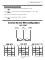
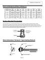
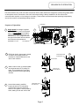
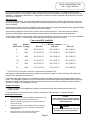
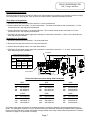
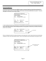
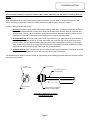
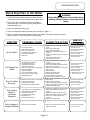
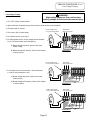
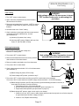
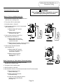
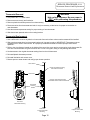
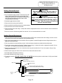
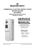
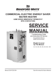
(To be performed ONLY by qualified service providers)
Commercial Electric Energy Saver:
E32-50S
E32-80R
E32-120R
Manual 239-47157-00B
Save this manual for future reference
E32 Medium Duty Commercial
Electric Water Heaters
Page
Service Procedure
Introduction ………………………………………………………………………. 2
---
Tools……………………………………………………………………………… 2
---
General Information ……………………………………………………………… 3
---
Sequence of Operation …………………………………………………………… 5
---
Field Conversion of kW, Voltage and Phase…………………………………….. 6
---
Troubleshooting ………………………………………………………………….
9
---
Heating Element Testing ……………...................................................................
11
E32-I
Line Voltage Testing………………...…………………………………………...
12
E32-II
Fuse and ECO Testing…........................................................................................
13
E32-III
Thermostat Operation Testing …….....................................................................
14
E32-IV
Thermostat Removal and Replacement …………………………………………. 15
E32-V
Heating Element Removal and Replacement ……………………………………. 16
E32-VI
Dip Tube and Anode Inspection and Replacement ……………………………… 17
E32-VII
Generic Parts List ………………………………………………………………... 18
---
This service manual is designed to aid service and maintenance professionals on the function, proper diagnosis and repair of
Bradford White medium duty commercial electric water heaters.
The text and illustrations in this manual provide step by step instructions to facilitate proper operation and troubleshooting
procedures. Contact the Bradford White Technical Support Group immediately if diagnosis can not be made using the
methods described in this service manual.
- Multi Meter.
- 1-½ Deep Well Socket (element removal).
- ¼" Nut Driver.
- Phillips Head Screw Driver.
- Thermometer.
- Drain Hose.
- Various Hand Tools: Pipe Wrench, Channel Locks, Pliers (common & needle nose), Wire cutters, Wire Strippers,
Flash Light.
Page 2
GENERAL INFORMATION
Commonly Used Formulas
Amps = Watts (for single phase units) Example 4500W/240V = 18.75A
Volts
Amps = Watts
(for balanced 3 phase units) Example 4500W/240V x 1.732 = 10.82A
Volts x 1.732
Watts = Amps x Volts Example 18.75A x 240V = 4500W
2
Ohms = Volts 2 Example (240V) / 4500W = 12.8 Ohms
Watts
BLACK
GREEN
RED
Grounding
Ungrounded
Ungrounded
240
120
120
Neutral
A
B
C
Neutral
A
C
208
208
A
C
277
120
240
240
208
BLACK RED
B
277
120
120
120
Neutral
120
120
RED
B
RED
480
240
BLACK RED
Page 3
277
480
RED
480
BLACK RED
GENERAL INFORMATION
Full Load Amperes-(Phase 1/Phase 3)
Input Kw
208V
240V
277V
380V
415V
480V
6
28.8/16.6
25/14.4
21.6
10
8.3
12.5/7.2
9
43.2/25
37.5/21.6
32.4
14
12.5
18.7/10.8
12
57.6/33.3
50/28.9
43.3
19
16.7
25/14.4
13.5
64.9/37.5
56.2/32.5
48.7
21
18.8
28.1/16.2
15
72.1/37.5
62.5/36.1
54.1
23
20.9
31.2/18
18
86.5/50
75/43.4
64
28
25
37.5/21.6
Surface Mounted Thermostats
E32 series medium duty commercial water heaters use only surface mounted thermostats. Surface mounted
thermostats are mounted into a bracket which holds the thermostat against the side of the tank. Surface mounted
thermostats respond to tank surface temperatures to sense a call for heat, set point temperature settings and high limit
(ECO) activation. It is import that the entire back surface of the thermostat is in full contact or flush with the tank. An
improperly mounted thermostat will lead to improper heater operation.
Manual
ECO (high limit)
Reset button
Surface Mount
Combination Thermostat/
ECO (high limit)
89T Series
Temperature
control Dial
Direct Immersion “Screw-in” Type Heating Element
1-½ Hex
Screw-in Flange
Terminal Block
0642
4500W 240V
RC02404524
Zinc Plated Copper or
Incoloy Sheath
Terminal Block
Screw
Element Rating Ink Stamped
on side of Terminal Block.
Page 4
SEQUENCE OF OPERATION
E32 series medium duty, field convertible commercial electric water heaters are designed to operate using single phase
or three phase service connections. One size fits all Internal fusing is factory installed for all units. When field
conversions are required, no fuse change is necessary. Three surface mounted thermostats operating independently
are used to control a corresponding heating element.
Fuse Block
Sequence of Operation.
1
2
3
Single phase line voltage is applied
across terminals L1 and L2 of terminal
block. Or Three phase line voltage is
applied to terminals L1 through L3 of
terminal block. Line voltage continues
through terminal block and fuse blocks
and connects to thermostats at
terminals L1 & L3.
Terminal Block
1
2
ECO (high limit) in thermostat is closed,
so there is line voltage present at
terminal L4 of thermostats and to one
side of each element.
ECO Closed
Water in tank is cold, so all thermostats
are closed at terminal T2 (calling For
heat). This completes the circuit and
allows current to flow through heating
element.
Power to one
side of element
4
4
As each thermostat is satisfied,
it opens at terminal T2 interrupting
current flow through the respective
element. The system is now in stand-by
mode, waiting for the next call for heat.
Thermostat closed
at terminal T2
Thermostat open
at terminal T2
Page 5
3
FIELD CONVERSION FOR:
KW, Voltage and Phase
The E32 series medium duty commercial electric water heaters are field convertible. This allows Qualified Service
Providers the ability to convert wattage, voltage and phase using a factory supplied conversion kit as required per the
installation. Underwriters Laboratories Inc. recognizes this procedure as herein presented and no deviation from these
instructions are allowed.
KW Conversion
All E32 series medium duty commercial water heaters are factory wired to the maximum electrical duty for which they
have been designed. Therefore, internal electrical components satisfy the maximum voltage and maximum electrical
current conditions.
These instructions do not allow for a modification that adds or deletes the number of heating elements originally supplied
with the heater; therefore such a modification must not be attempted.
Special factory prepared “Conversion Kits” must be used for these conversions. These kits contain the heating
elements, element gaskets and product labeling overlays related to the newly created electrical parameters.
18 KW heaters suitable for operation with 208vac cannot be created by conversion since there are no “kits” established
for this electrical system. These heaters can be obtained by ordering directly from the factory.
Conversion Kit Available
Total
Element
Heater KW Wattage
Required
---------- Kit Part Numbers ---------208 volts
240 volts
480 volts
6
2000
265-43942-13
265-43942-07
265-43942-01
9
3000
265-43942-14
265-43942-08
265-43942-02
12
4000
265-43942-15
265-43942-09
265-43942-03
13.5
4500
265-43942-16
265-43942-10
265-43942-04
15
5000
265-43942-17
265-43942-11
265-43942-05
18
6000
265-43942-18*
265-43942-12
265-43942-06
*265-43942-18 will require control box replacement (included in kit).
Following the heating element removal and replacement instruction on page 16, remove elements and replace with
elements from appropriate kit listed above.
The heaters rating plate will need to be modified because the conversion altered the electrical characteristics of the
heater. This rating plate is placed on every Commercial Electric water heater produced by Bradford White Corporation.
Element kits above contain rating plate label overlays related to the newly created electrical parameters. Follow the
instruction on page 8 For placement of overlays.
Voltage Conversion
1. Voltage conversion is accomplished by replacing the existing elements with elements that are rated at the
required voltage.
2. To accomplish this conversion refer to the above procedure for KW Conversion ---- Element Changes.
Control Box Conversion
1.
Open front panel of control box installed on water heater and
disconnect the (6) load wires from fuse blocks.
2.
Remove (4) screws joining control box to water heater and
remove control box.
3.
Install new control box onto the water heater by feeding the
wires through the back of the control box and reinstall (4)
mounting screws.
4.
Reconnect wires to new fuse blocks. Be certain to
match wire colors to Line side of fuse blocks.
Page 6
NOTICE
Control box conversion is ONLY required
when converting water heater to 18kw 208v
(Kit# 265-43942-18)
CAUTION
Use caution to not damage any of the wire
insulation when removing control box.
FIELD CONVERSION FOR:
KW, Voltage and Phase
Electrical Phase Conversion
Electrical phase conversion will require a change from single-phase to three-phase or an opposite conversion change
from three-phase to single-phase. Each of these conversions will be explained separately as follows:
Three-Phase to Single-Phase
1. Disconnect blue and yellow wires from terminal L-3 of the terminal block
2. Connect yellow wire to terminal L-1 of the terminal block. The black wires should remain connected to L-1 of the
terminal block as it was originally manufactured.
3. Connect blue wire to terminal L-2 of the terminal block. The red wires should remain connected to L-2 of the
terminal block as it was originally manufactured.
4. Field wiring for the heater power supply will eventually be connected to terminals L-1 and L-2 of the terminal block
when the product is installed.
Single-Phase to Three-Phase
1. Disconnect yellow wire from terminal L-1 of the terminal block
2. Disconnect blue wire from terminal L-2 of the terminal block
3. Connect blue and yellow wires to L-3 of the terminal block
4. Field wiring for the heater power supply will eventually be connected to terminals L-1, L-2, and L-3 of the terminal
block when the product is installed.
Fuse Block
Three Phase and Single Phase
Connections at Terminal Block
Phase
Terminal Block
L2
L3
L1
Single
BK & Y
Wires
R & BL
Wires
Three
BK
Wire
R
Wire
BL & Y
Wires
Terminal Block
E32 Series Phase Conversion Rating Plate Overlay Kits
Volt
6KW
Conversion Kit
Volt
9KW
Conversion Kit
Volt
12KW
Conversion Kit
208
240
480
265-45246-13
265-45246-07
265-45246-01
208
240
480
265-45246-14
265-45246-08
265-45246-02
208
240
480
265-45246-15
265-45246-09
265-45246-03
Volt
13.5KW
Conversion Kit
Volt
15KW
Conversion Kit
Volt
18KW
Conversion Kit
208
240
480
265-45246-16
265-45246-10
265-45246-04
208
240
480
265-45246-17
265-45246-11
265-45246-05
208
240
480
265-45246-18
265-45246-12
265-45246-06
The heaters rating plate will need to be modified because the conversion altered the electrical characteristics of the
heater. This rating plate is placed on every Commercial Electric water heater produced by Bradford White Corporation.
Phase conversion kits above contain rating plate overlays related to the newly created electrical parameters. Follow the
instruction on page 8 For placement of overlays.
Page 7
FIELD CONVERSION FOR:
KW, Voltage and Phase
Rating Plate Modification
The heaters rating plate will need to be modified because the conversion altered the electrical characteristics of the
heater. Refer to the illustration below that displays a typical commercial electric rating plate that is to be altered. This
rating plate is placed on every Commercial Electric water heater produced by Bradford White Corporation. Locate this
rating plate on the heater you have just converted.
BRADFORD WHITE CORPORATION
200 LAFAYETTE ST. MIDDLEVILLE MI 49333
Model No: E32-50S3
Serial No: ZB2564812
Cap.
50(gal.)/189.3(liters)
Press:
Test 300(psi), Working 150(psi)
Volts
240
Max Temp 180°
Phase
Three
Amps 43.3
Kw Each 6
Total Kw 18
Wattage Rating Based Upon 60 Hz
3 Elements
Locate the adhesive backed label (marked as part # 238-43990-00) (see illustration below) that was provided inside the
kit. It is marked with the new electrical data that is accurate for the conversion just executed. The kit will contain two
labels for this voltage and KW. One for three phase and one for single phase. Select the correct label for the electrical
phase in this conversion.
Volts
480
Max Temp 180°
Phase
Three
Amps 7.2
Kw Each 2
Total Kw 6
Wattage Rating Based Upon 60 Hz
Part number
3 Elements
238-43990-00
Remove the adhesive peel strip and place this label onto the rating plate in such a manner that the new electrical data
will appear in place of the data originally marked. Refer to the illustration below that displays the rating plate revision.
BRADFORD WHITE CORPORATION
200 LAFAYETTE ST. MIDDLEVILLE MI 49333
Model No: E32-50S3
Serial No: ZB2564812
Cap.
50(gal.)/189.3(liters)
Press:
Test 300(psi), Working 150(psi)
Overlay placed over old
rating plate data
Volts
480
Max Temp 180°
Phase
Three
Amps 7.2
Kw Each 2
Total Kw 6
Wattage Rating Based Upon 60 Hz
3 Elements
238-43990-00
Page 8
TROUBLESHOOTING
Most common cause for improper electric water heater operation can be linked to heating element
failure.
When troubleshooting an electric water heater with the incidence of “No Hot Water” or “Insufficient Amount of Hot
Water” It is always a good idea to check the heating elements first following the procedure on page 11.
Common Heating Element Failures Are:
1. Dry Firing. Element may be partially submerged in water or most likely, completely exposed with no water in
tank. In some cases sediment or lime build up around an element can eventually cause an air pocket, and
within seconds, result in a dry fired element. At this point the element becomes inoperative. When element
replacement is required, be sure tank is full of water prior to energizing the water heater.
2. Grounded Element. An element with a short circuit to ground will in most cases cause the circuit breaker in
the service panel to open or shut off. In some cases there may not be enough current draw for the circuit
breaker to open. This will allow the heating element to be in continuous operation resulting in over heated
water, limited only by the ECO or Energy Cut Off located in the thermostat. Repeated actuation of the ECO
reset button on the thermostat usually is the result of a grounded element.
3. Sediment build up. Slow hot water recovery can usually be traced back to sediment or lime build up around
heating element. Sediment build up can also over time cause a dry fired element.
The illustration below shows a common “Screw-In” type heating element identifying certain features commonly referred
to throughout this manual.
1-½ Hex
Screw-in Flange
Terminal Block
0642
4500W 240V
RC02404524
Zinc Plated Copper or
Incoloy Sheath
Terminal Block
Screw
Element Rating Ink Stamped
on side of Terminal Block.
Typical Direct Immersion “Screw-In”
Type Heating Element
Page 9
TROUBLESHOOTING
Quick Step Plan to Hot Water
WARNING
High voltage exposure. Use caution when
making voltage checks to avoid personal
injury.
1. TURN OFF power to water heater and check all wire
connections to insure they are tight and corrosion free.
2. Turn power “ON” and determine that line voltage is
present (see pg 12), and the high limit (ECO) has not
actuated (see pg 13).
3. Check for blown fuse (see pg 13).
4. Check for inoperative heating element (see procedure on page 11).
5. Check for proper thermostat operation (see pg 14). NOTE: Thermostat testing procedures
assume items 2, 3 and 4 above are in working order.
SYMPTOM
No Hot Water
PROBABLE CAUSE
CORRECTIVE ACTION
1. Check fuses or circuit breakers at service
panel.
2. Check water heater fuses.
3. Check all wire connections.
4. Check heating element(s). Replace as
needed.
5. Check thermostat(s) operation. Replace as
needed.
6. Check ECO. Reset or replace
thermostat(s) as needed.
1. No Power to heater.
2. Blown water heater fuses.
3. Loose wire connections.
4. Inoperative heating elements.
5. Inoperative thermostat.
6. Open ECO.
SERVICE
PROCEDURE
2. See Service Procedure
E32-III, Page 13
4. See Service Procedure
E32-I, Page 11.
5. See Service Procedure
E32-IV, Page 14.
6. See Service Procedure
E32-III, Page 13
Not Enough Hot
Water
1. Inoperative heating element.
2. Thermostat(s) set to low.
3. Inoperative thermostat(s).
4. Loose wire connection.
5. Sediment or lime build up on element(s).
6. High demand period.
7. Undersized heater.
8. Very cold inlet water to heater.
9. Plumbing connections reversed.
10. Damaged dip tube.
1. Check heating element(s), replace as
needed.
2. Increase thermostat setting.
3. Check thermostat(s), replace as needed.
4. Check all wire connection.
5. Remove heating element(s) and check for
lime build up.
6. Reduce demand.
7. Replace with larger heater.
8. Temper water to heater.
9. Correct plumbing connections.
10. Check dip tube, replace as needed.
1. See Service Procedure
E32-I, Page 11.
3. See Service Procedure
E32-IV, Page 14.
5. See Service Procedure
E32-VI, Page 16.
10. See Service Procedure
E32-VII, Page 17.
Slow Hot Water
Recovery
1. Sediment or lime build up on element(s).
2. Loose wire connections.
3. Inoperative thermostat(s).
4. Derated heating element installed.
1. Remove heating element(s) and check for
lime build up.
2. Check all wire connections.
3. Check thermostat(s), replace as needed.
4. Check terminal block of element for proper
voltage and wattage rating.
1. See Service Procedure
E32-VI, Page 16.
3. See Service Procedure
E32-IV, Page 14.
1. Thermostat(s) not in contact with tank.
2. Grounded heating element(s).
3. Thermostat set to high.
4. Inoperative thermostat(s).
5. Inoperative ECO.
6. Undersized water heater.
1. Position thermostat flush with tank surface.
2. Check heating element(s). Replace as
needed.
3. Adjust thermostat(s) to desired setting.
4. Check thermostat(s), replace as needed.
5. Check ECO, replace thermostat as
needed.
6. Replace with larger heater.
1. See Service Procedure
E32-V, Page 15.
2. See Service Procedure
E32-I, Page 11.
4. See Service Procedure
E32-IV, Page 14.
5. See Service Procedure
E32-III, Page 13.
1. Remove and clean heating elements.
Replace as needed.
1. See Service Procedure
E32-VI, Page 16.
Over Heated
Water or
Continues
Operation
Noisy (singing or
hissing) Elements
1. Lime formation on elements.
Page 10
SERVICE PROCEDURE E32-I
Heating Element Testing
Testing For Open Or Burned Out Element.
WARNING
High voltage exposure. Be sure power is turned
OFF to water heater prior to performing this
procedure.
Step 1. TURN OFF POWER TO WATER HEATER.
Step 2. Remove thermostat/element access cover(s)
from front of water heater. Remove insulation
and plastic cover from thermostat.
Step 3. Disconnect wires from heating element.
Step 4. Set multi-meter to “ohms” setting.
Step 5. Touch probes of multi-meter to screw
terminals of heating element
(see illustration 1).
Step 6. Reading should be 12.8 ohms (±6%) for a 240
volt, 4500 watt element, see table below:
2
Ohms = Volts
Watts
A reading outside the range using the formula
above (±6%), indicates a bad element and the
element must be replaced.
Ohms of electrical Resistance
Element Screw Terminals
Voltage Rating of Element
Illustration 1
Element
Wattage
208
240
480
2000
3000
4000
4500
5000
6000
21.6
14.4
10.8
9.6
8.7
7.2
28.8
19.2
14.4
12.8
11.5
9.6
115.2
76.8
57.6
51.2
46.1
38.4
NOTE
Disconnect
element
Wires
Testing For Heating Element Short Circuit To
Ground.
Step 1. TURN OFF POWER TO WATER HEATER.
NOTE
Disconnect
element
Wires
Step 2. Remove access cover(s) from front of water
heater. Remove insulation and plastic cover
from thermostat.
Step 3. Disconnect wires from heating element.
Element Screw Terminal
Step 4. Set multi-meter to “ohms” setting.
Meter Probe
Step 5. Touch one probe of multi-meter to either screw
terminal of heating element and the other on
the element flange (see illustration 2). There
should be no reading on the ohm meter. Any
reading indicates a grounded element and the
element must be replaced. Repeat this step for
the other screw terminal.
Element Flange
Illustration 2
Page 11
SERVICE PROCEDURE E32-II
Line Voltage Testing
Line Voltage Testing
WARNING
High voltage exposure. Use caution when
making voltage checks to avoid personal injury.
1. Turn “OFF” power to water heater.
2. Open control box located at the top of the heater to allow access to terminal block.
3. Set multi-meter to volts AC.
Check voltage across
L1 & L2 of terminal block
4. Turn power “ON” to water heater.
Single phase
Service from panel
5. For 3 phase service, go to step 7.
6. For single phase service, check voltage across terminals
L1 & L2 of terminal block (see illustration 3).
A) Rated voltage IS present, power to the water
heater is okay.
Illustration 3
B) Rated voltage NOT present, Check circuit breaker
at service panel.
Check voltage across
L1 & L2 of terminal block
Three phase
Service from panel
7. For 3 phase service check across L1 & L2 and across
L1 and L3 (see illustrations 4 & 5)
A) Rated voltage IS present, power to the water
heater is okay.
B) Rated voltage NOT present, Check circuit breaker
at service panel.
Illustration 4
Check voltage across
L1 & L3 of terminal block
Three phase
Service from panel
Illustration 5
Page 12
SERVICE PROCEDURE E32-III
Fuse Testing
Fuse Testing
1. Turn “OFF” power to water heater.
2. Open control box located at the top of the heater to
allow access to fuse block.
WARNING
High voltage exposure. Be sure power is turned
OFF to water heater prior to performing this
procedure.
3. Disconnect wire leads from fuse block. NOTE: It may be
necessary to label wires for proper re-connection when
finished.
4. Set multi-meter to the “Ohms” setting.
5. Check continuity across upper and lower screw terminal
of fuse block for each individual fuse, six total
(see illustration 6).
A) Continuity IS present, fuse is okay.
B) Continuity NOT present, Replace with new fuse
Class “G”, 480 Volt MAX, 30 Amp.
Illustration 6
ECO (high limit) testing
1. This procedure assumes line voltage and
fuses are in working order.
2. Turn power “OFF” to water heater.
3. Remove thermostat/element access cover(s) located
near the bottom of the water heater.
WARNING
High voltage exposure. Use caution to avoid
personal injury during this procedure.
4. Remove insulation and plastic cover from thermostat.
ECO reset
button
5. Turn power “ON” to water heater.
6. Check voltage across terminals L1 & L4 for all thermostats
(see illustration 7).
A) Rated Voltage IS present, ECO is okay.
B) Rated voltage NOT present, proceed to step 7.
7. Turn power “OFF” to water heater and firmly press ECO reset button on thermostat(s).
Turn power “ON” to water heater and recheck voltage across terminals L1 & L4 of thermostat(s).
A) Rated voltage IS present, the ECO has previously opened indicating the water in the tank, at
some point did overheat, Check the following:
1. Thermostat must be in full contact with tank.
Illustration 7
2. Be sure heating element(s) is not shorted to ground (see page 11).
3. Proper thermostat operation (see procedures on page 14).
B) Rated voltage NOT present, water in tank may be over heated.
1. If water is hot, turn “OFF” power to water heater and flow water through tank to cool below set point
of upper thermostat. Recheck voltage per step 6.
2. If water is cool, Replace thermostat(s).
Page 13
SERVICE PROCEDURE E32-IV
Thermostat Testing
Thermostat Operation Testing
WARNING
High voltage exposure. Use caution to avoid
personal injury during this procedure.
Water In Tank Is Cold With Power ON.
1. This procedure assumes line voltage, ECO and
elements are in working order.
2. Turn power “ON” to water heater.
3. Set multi-meter to “Volts AC”.
4. Check across terminals L1 & L3 of thermostat
(see illustration 8)
A) Rated voltage NOT present,
Check fuses.
B) Rated voltage IS present,
proceed to next step.
5. Check across terminals L4 and T2 of
thermostat (see illustration 9).
A) Rated voltage NOT present,
Recheck ECO. If ECO is okay,
replace thermostat.
Illustration 8
Illustration 9
B) Rated voltage IS present, okay thermostat is
calling for heat, proceed to next step.
6. Check across element terminals
(see illustration 10).
A) Rated voltage NOT present,
check wire connections from
thermostat to element.
B) Rated voltage IS present,
Repeat element testing
see page 11.
Water Temperature In Tank Is Above Thermostat Setting.
1. This procedure assumes line voltage, ECO and
elements are in working order.
Illustration 10
2. Turn power “ON” to water heater.
3. Set multi-meter to “Volts AC”.
4. See illustration 9 above, check across terminals L4 and T2 of thermostat.
A) Rated voltage IS present,
replace thermostat.
B) Rated voltage NOT present,
thermostat is okay.
C) Lower than rated voltage IS present,
recheck for grounded element
(see page 11).
Page 14
SERVICE PROCEDURE E32-V
Thermostat Removal and Replacement
Thermostat Removal
WARNING
High voltage exposure. Be sure power is
“OFF” when performing this procedure.
1. Turn power “OFF” To water heater.
2. Remove access cover(s) and insulation.
3. Remove plastic thermostat protector from thermostat(s).
4. Disconnect wires from thermostat terminals. It may be necessary to label wires for proper re-connection to
new thermostat.
5. Note thermostat temperature setting for proper setting of new thermostat.
6. Slide thermostat upwards and out of mounting bracket.
Thermostat Replacement
1. Use a stiff brush to remove any debris or loose scale from tank surface where new thermostat will be installed.
2. Slide new thermostat down into thermostat bracket until it snaps into place. IMPORTANT! Thermostat must set
completely flat or flush to tank surface. An improperly installed thermostat will cause improper water heater
operation.
3. Refer to the wire diagram located on the inside of the control box cover and re-connect wires to the thermostat. Be
sure wire connections are snug and corrosion free. Do not over tighten, doing so may damage thermostat.
4. Set thermostat to the original thermostat setting found on the old thermostat.
5. Re-install plastic thermostat protector.
6. Re-install insulation and access cover.
7. Restore power to water heater and verify proper heater operation.
Tank Surface
Proper Thermostat mounting
flush with tank surface
Thermostat
Improper Thermostat mounting.
Thermostat not flush with tank surface
Thermostat
mounting
bracket
Front View
Thermostat Mounting
Side View
Proper Thermostat
Mounting
Page 15
Side View
Improper Thermostat
Mounting
SERVICE PROCEDURE E32-VI
Heating Element Removal
and Replacement
WARNING
High voltage exposure. Be sure power is
“OFF” when performing this procedure.
Heating Element Removal
1. Turn power “OFF” To water heater.
2. Turn off cold water supply to heater. Connect hose to drain
spigot of water heater and route to an open drain. Open
a nearby hot water faucet to vent heater for draining. Open
drain spigot of water heater and allow heater to drain
to a point below the Element(s).
WARNING
Heater components and stored water may be
HOT when performing the following steps in
this procedure. Take necessary precaution to
prevent personal injury.
3. Close drain spigot and remove hose.
3. Remove access cover(s) and insulation.
4. Remove plastic thermostat protector from thermostat(s).
5. Disconnect wires from element terminals.
6. Remove element from tank using 1-½ deep well socket or appropriate wrench. Unscrew element counter-clockwise to
remove from tank.
7. Be sure to remove old element gasket from the tank. It is not recommended to be re-used.
Heating Element Replacement
1. Check element terminal block for proper electrical rating. NOTE: Some elements have dual ratings, be sure to check
all surfaces of the element terminal block (see illustration below).
2. Apply new element gasket to the new element. Be sure gasket is seated flat against element flange without rolls or
gaps (see illustration below).
3. Clean any debris from element fitting on tank. Lubricate element threads as needed with thread lubricant.
4. Thread new element clockwise into tank. Tighten element using 1-½ deep well socket or appropriate wrench. Do not
over tighten, over tightening may damage element gasket.
5. Reconnect wires to element, be sure connections are snug and corrosion free. Do not over tighten, doing so may
damage terminal block.
6. Resume water supply to heater, be sure tank is full of water and check for leaks.
7. Re-install plastic thermostat protector(s).
8. Re-install insulation and access cover(s).
9. To resume operation, BE SURE TANK IS FULL OF WATER and restore power to water heater. Verify proper heater
operation.
Element Rating.
Example: (4500 Watt, 240 Volt)
Date Code
0642
4500W 240V
RC02404524
Element Flange
Element Gasket Seated Flat Against
Element Flange Without Rolls or Gaps
Terminal
Block
Manufacturer Identification
Page 16
SERVICE PROCEDURE E32-VII
Dip Tube and Anode Inspection and
Replacement
Dip Tube Inspection and Replacement
WARNING
Heater components and stored water may be HOT when performing the following steps in
this procedure. Take necessary precaution to prevent personal injury.
Step 1.
Turn power “OFF” to water heater.
Step 2.
Turn off cold water supply to heater. Connect hose to drain spigot of water heater and route to an open drain.
Open a nearby hot water faucet to vent heater for draining. Open drain spigot of water heater and allow
heater to drain to a point below the inlet connection nipple.
Step 3.
Close drain spigot and remove hose.
Step 4.
Disconnect inlet nipple from plumbing system.
Step 5.
With an appropriate wrench, remove inlet nipple/dip tube from the water heater. Use caution not to damage
nipple threads.
Step 6.
Visually Inspect inlet nipple/dip tube. Inlet nipple/dip tube should be free of cracks and any blockage.
Hydro-jets located near the bottom of the dip tube should be open and free of any blockage.
Anti-siphon hole located approximately 6" from the bottom of nipple, should be free of any blockage.
Any damage such as cracks, restriction due to deformation or unintentional holes are not field repairable
and the inlet nipple/dip tube must be replaced.
Step 7.
Upon completion of inspection or subsequent replacement, reinstall inlet nipple/dip tube into heater. Connect
nipple to plumbing system, close spigot and remove drain hose, resume water supply and refill heater with
water.
Step 8.
To resume operation, BE SURE TANK IS FULL OF WATER and turn power “ON” to water heater.
Anode Inspection and Replacement
Step 1.
Turn power “OFF” to water heater.
Step 2.
Turn off cold water supply to heater. Connect hose to drain spigot of water heater and route to an open drain.
Open a nearby hot water faucet to vent heater for draining. Open drain spigot of water heater and allow
heater to drain to a point below the outlet connection nipple.
Step 3.
Close drain spigot and remove hose.
Step 4.
Disconnect outlet nipple from plumbing system.
Step 5.
With an appropriate wrench, remove outlet nipple/anode from the water heater. Use caution not to damage
nipple threads.
Step 6.
Visually Inspect outlet nipple/anode. Outlet nipple/anode should show signs of depletion, this is normal.
If depletion is ½ of the original anode diameter (original diameter approximately ¾”), replacement is
recommended. If any of the
steel core of the anode is exposed, replacement is recommended.
Step 7.
Upon completion of inspection or subsequent replacement, reinstall outlet nipple/anode into heater. Connect
nipple to plumbing system, close spigot and remove drain hose, resume water supply and refill heater with
water.
Step 8.
To resume operation, BE SURE HEATER IS FULL OF WATER and turn power “ON” to water heater.
Page 17
Generic Parts List
1. Hot Water Outlet Anode
2. T&P Relief Valve
3. Cold Water Inlet Dip Tube
4. Control Box
5. Ground Lug
6. Fuse
7. Fuse Block
8. Terminal Block
9. Brass Drain Valve
10. Thermostat Mounting Bracket
11. Element Gasket
12. Heating Element
13. Thermostat Surface Mount
14. Thermostat Protector
15. Thermostat/Element Access Cover
16. ASSE Approved Mixing Valve (optional)
Page 18
Email
[email protected]
[email protected]
www.bradfordwhite.com