1
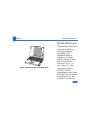
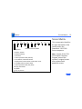
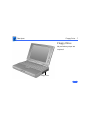
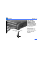
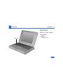
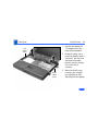
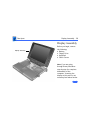
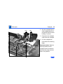
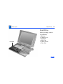
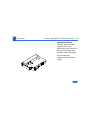
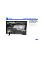
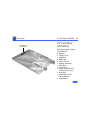
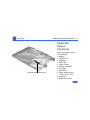
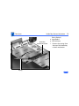
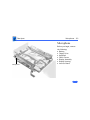
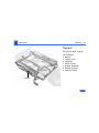
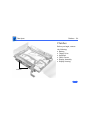
K Service Source
PowerBook 190/5300 Series
Macintosh PowerBook 190/66, 190cs/66, 5300/100,
5300cs/100, 5300c/100, and 5300ce/117
K Service Source
Basics
PowerBook 190/5300 Series
Basics
Product Overview - 1
Product Overview
Figure: PowerBook 190, PowerBook 5300
The PowerBook 5300 Series
introduces a number of
technology and design
innovations to the
PowerBook family of
computers. The series
features a Power PC 603e
RISC microprocessor
running at 100 or 117
MHz, built-in PC Card
technology (formerly
PCMCIA), infrared
communication, and a video
expansion board (to support
external monitors). Also
included in the series are
Basics
Product Overview - 2
four different PowerBook displays: a monochrome FSTN
display, a color FSTN display, and color TFT and TFT/SVGA
displays.
The PowerBook 190 Series features a 68LC040 central
processor running at 33 MHz and offers the infrared board,
video board, logic board, and TFT display as upgrade options.
Basics
PowerBook 5300 Series Configurations - 3
PowerBook 5300 Series Configurations
The PowerBook 5300 Series computers come in the
following configurations:
PowerBook 5300
• Processor: 100 MHz PowerPC 603e
• RAM/Hard drive: 8 MB/500 MB
• Display: 9.5-inch greyscale
• Battery: 2.5–4-hour NiMH
• Weight: 5.9 pounds
PowerBook 5300cs
• Processor: 100 MHz PowerPC 603e
• RAM/Hard drive: 8 MB/500 MB or 16 MB/750 MB
• Display: 10.4-inch dual-scan color
• Battery: 2.5–4-hour NiMH
• Weight: 6.2 pounds
Basics
PowerBook 5300 Series Configurations - 4
PowerBook 5300c
• Processor: 100/117 MHz PowerPC 603e
• RAM/Hard drive: 8 MB/500 MB or 16 MB/750 MB
• Display: 10.4-inch active-matrix color
• Battery: 2.5–4-hour NiMH
• Weight: 6.2 pounds
PowerBook 5300ce
• Processor: 100/117 MHz PowerPC 603e
• RAM/Hard drive: 32 MB/1 GB
• Display: 10.4-inch SVGA active-matrix color
• Battery: 2.5–4-hour NiMH
• Weight: 6.2 pounds
Basics
PowerBook 190 Series Configurations - 5
PowerBook 190 Series Configurations
The PowerBook 190 Series computers come in the following
configurations:
PowerBook 190
• Processor: 66/33 MHz 68LC040
• RAM/Hard drive: 4 MB/500 MB or 8 MB/500 MB
• Display: 9.5-inch greyscale
• Battery: 2.5–4-hour NiMH
• Weight: 6 pounds
PowerBook 190cs
• Processor: 66/33 MHz 68LC040
• RAM/Hard drive: 4 MB/500 MB or 8 MB/500 MB
• Display: 10.4-inch dual-scan color
• Battery: 2.5–4-hour NiMH
• Weight: 6.3 pounds
Basics
Repair Strategy - 6
Repair Strategy
Service the PowerBook 190 and PowerBook 5300 Series
computers through module exchange and parts replacement.
Customers can request on-site service from an Apple
Authorized Service Provider Plus (AASP+) Apple Assurance
(US only), or request a courier through the Apple Canada
Technical Answerline (Canada only). They can also choose
carry-in service from an AASP.
Ordering
Apple Service Providers planning to support the computer
systems covered in this manual may purchase Service
modules and parts to develop servicing capability. To order
parts, use the AppleOrder (US only) or ARIS (Canada only)
system and refer to “Service Price Pages.”
Basics
Repair Strategy - 7
Large businesses, universities, and K-12 accounts must
provide a purchase order on all transactions, including
orders placed through the AppleOrder (US only) or ARIS
(Canada only) system.
USA Ordering
US Service Providers not enrolled in AppleOrder may fax
their orders to Service Provider Support (512-9088125) or mail them to
Apple Computer, Inc.
Service Provider Support
MS 212-SPS
Austin, TX 78714-9125
For US inquiries, please call Service Provider Support at
800-919-2775 and select option #1.
Basics
Repair Strategy - 8
Canadian Ordering
Canadian Service Providers not enrolled in ARIS may fax
their orders to Service Provider Support in Canada
(1-800-903-5284). For Canadian inquiries, please call
Service Provider Support at 905-513-5782 and select
option #3.
Basics
Warranty/AppleCare/ARIS - 9
Warranty/AppleCare/ARIS
US Only
The PowerBook 190 and PowerBook 5300 Series computers
are covered under the Apple One-Year Limited Warranty.
The AppleCare Service Plan is also available for these
products. Service Providers are reimbursed for warranty
and AppleCare repairs made to these computers. For pricing
information, refer to “Service Price Pages.”
Repair Extension Program
A REA program for some PowerBook 190 and PowerBook
5300 Series computers is in effect until June 2002. For
information on this program, refer to the Programs manual,
Ordering & Repairing chapter, and Repair Extension
Authorization (REA) Programs section of Service Source.
Basics
Warranty/AppleCare/ARIS - 10
Canada Only
The PowerBook 190 and PowerBook 5300 computers are
covered under first-year AppleCare. The Extended
AppleCare Service Plan is also available for these products.
Service Providers are reimbursed for first-year warranty
and Extended AppleCare repairs made to these computers.
For pricing information, refer to “Service Price Pages.”
Basics
Rear Panel - 11
Rear Panel
The rear panel contains the
I/O ports, reset actuator,
and infrared window. The
picture to the left shows the
location of these features.
Infrared Video Reset Sound Sound
Window Port Actuator Input Output
Port
Port
SCSI
Port
(HDI-30)
External
Modem/
Printer
Port
Power
Adapter
Port
Apple
Desktop
Bus (ADB)
Port
Basics
1
*2 *3
Screw Matrix - 12
4
5
6
*7
Screw Matrix
8
Order Screw Kit 076-0639
1 Keyboard
2 Display, clutches
3 Display assembly
4 Hard drive
5 Video expansion board (internal)
6 CPU stiffener, hard drive bracket
7 Display bezel, inverter board, center clutch cover
8 Trackpad button & closure switch
9 Video expansion board (rear panel)
10 Floppy mechanism
11 Speaker
*
May be patchlock
9
10
11
This screw matrix identifies
the type and location of the
screws used in the
PowerBook 190/5300
Series computers.
Note: As part of the 190/
5300 Repair Extension
Program, some of the
systems’s original screws
were replaced with
patchlock screws.
Basics
Cable Matrix - 13
Cable Matrix
For a matrix of cables that work with specific models of the
PowerBook family of computers, select the PowerBook Cable
Matrix located in Hardware/Compatibility Charts.
Basics
Power Information - 14
Power Information
Use the following information on the batteries and power
adapter to ensure the best use of these systems and to
recognize and prevent problems. For instructions on battery
and power adapter verification, see the Additional
Procedures chapter of this manual.
Battery Matrix
For a matrix of batteries that work with specific models of
the PowerBook family of computers, select the PowerBook
Battery Matrix located in Hardware/Compatibility Charts.
Basics
Power Information - 15
Battery-Handling Guidelines
The following are guidelines for properly handling the
PowerBook 190/5300 Series batteries:
Warning: NiMH batteries contain toxic materials. Send
undamaged, dead batteries to Apple for recycling—do not
discard dead batteries with other waste. If battery is
damaged, do not return it to Apple. Dispose of damaged
batteries according to local ordinances. Review battery
handling and disposal instructions in Safety Information in
Bulletins/Safety.
• Handle the battery carefully. Do not drop, puncture,
disassemble, mutilate, or incinerate it.
• Do not short-circuit the battery terminals.
Basics
Power Information - 16
• Do not leave a battery in the computer for longer than a
week without plugging in the power adapter.
• Keep the contact cover on the battery when the battery is
not in the computer.
• Do not leave the battery in hot locations (such as the
trunk of a car).
• Keep the battery in a cool, dark place; do not store it for
longer than 6 months without recharging.
• Completely discharge and then recharge the battery once
every 90 days.
• Fully charge a replacement battery before using it; Apple
ships batteries in a partially charged state.
Basics
Power Information - 17
Nickel-Metal-Hydride
Batteries
The PowerBook 190/5300
Series computers use
nickel-metal-hydride
(NiMH) batteries. Each
battery provides power for
up to 4 hours of work time,
depending on the system
configuration and battery
conservation features
employed.
Basics
PC Card Handling - 18
PC Card Handling
Two PC Card slots (formerly PCMCIA) are a feature in the
PowerBook 190/5300 Series. The two slots accept a variety
of third-party PC Cards.
There are three types of PC Cards: Type I (3 mm), Type II
(5 mm), and Type III (10.5 mm). Type I and Type II cards
fit in either the upper or lower slot of the PC Card unit.
Type III cards fit in the lower slot and take up both slots.
The following are guidelines for properly handling the PC
Card:
• Use only cards that are compatible with the PC Card unit.
Refer to the compatibility information that came with the
card. If you cannot find the compatibility information,
call the card vendor.
Basics
PC Card Handling - 19
• Do not insert anything other than a PC Card into the card
slots.
• The PC Card eject button functions regardless of whether
the computer is on or off.
• Before ejecting a PC Card, make sure nothing is blocking
the slot. To immediately reinsert the card, pull it out an
inch or more and then push it back in.
• Eject a PC Card using the PCMCIA Eject control panel or
the PCMCIA Quick Eject module in the computer's Control
Strip.
K Service Source
Specifications
PowerBook 190/5300 Series
Specifications
Introduction - 1
Introduction
You can also find specifications information for this product in the
Spec Database, which you can access in one of three ways:
— Launch it directly by double-clicking the Apple Spec Database
runtime alias at the top level of the Main Service Source CD.
— Select "Apple Spec Database" from the Service Source dropdown main menu.
— Click the Acrobat toolbar icon for the database, which is near
the right end of the toolbar with the letters "SP."
Specifications
Processor - 2
Processor
CPU
PowerBook 190
Series
Motorola 68LC040 microprocessor running at 33 MHz
PowerBook 5300
Series
PowerPC 603e RISC microprocessor running at 100 MHz
(5300/100, 5300c/100, 5300cs/100) or 117 MHz
(5300ce/117)
All Systems
Require system software version 7.5.2 or later with System
enabler: PowerBook Enabler 5300/2300/190 version 1.01
Specifications
Addressing
Processor - 3
32-bit internal registers
32-bit address bus
32-bit data bus
Specifications
Memory - 4
Memory
RAM
RAM installed on the logic board:
4–8 MB PB 190/66 and 190cs/66
8
MB PB 5300/100
8–16 MB PB 5300c/100 and 5300cs/100
32
MB PB 5300ce/117
Expandable up to 64 MB with third-party RAM expansion card
ROM
2– 4 MB soldered on the logic board
PRAM
256 bytes of parameter memory
Specifications
Memory - 5
VRAM
Logic Board
512K for passive display configurations; 512K and 1 MB for
active display configurations
Video Board
512K; will support 1 MB
Specifications
Disk Storage - 6
Disk Storage
Floppy Drive
15 mm high, internal, 1.4 MB Apple SuperDrive
Hard Drives
2.5 in.; 500 MB, 750 MB, and 1.1 GB IDE capacities
Specifications
I/O Interfaces - 7
I/O Interfaces
SCSI
HDI-30 SCSI port with 1.5 MB/sec. transfer rate
Supports up to six external SCSI devices
Connect SCSI device to computer with HDI-30 SCSI system cable.
Apple Desktop Bus
Apple Desktop Bus (ADB) port
200 mA maximum current draw for all ADB devices
Serial
RS-422 serial port; mini DIN-8 connector
Sound
Stereo line-in port
Stereo sound-out headphone jack; standard 3.5 mm stereo
miniplugs
Specifications
I/O Interfaces (Continued) - 8
I/O Interfaces (Continued)
Video
Micro DV-14 video-out port; 8 bit, 256 color video output
(optional on PowerBook 190)
Supports most Macintosh monitors, VGA monitors, and SVGA
monitors
PC Card Slots
Allow use of either two Type I and Type II cards, or one Type III
card
Infrared
Supports LocalTalk
Power Adapter
Power adapter port
Specifications
I/O Devices - 9
I/O Devices
Keyboard
Built-in keyboard with 12 function keys
76 keys domestic, 77 keys ISO
Two-level tilt adjustment (extending computer feet)
Trackpad
Solid-state trackpad
Microphone
Electret, omnidirectional
Output voltage of 4 mV, peak to peak
Specifications
Sound - 10
Sound
Sound Generator
Apple sound chip provides 16-bit sound capable of driving stereo
headphones or other stereo equipment through the sound jack
Specifications
Video - 11
Video
PB 190/66 and 5300/
100 Video Display
PB 190cs/66 and
5300cs/100 Video
Display
PB 5300c/100 Video
Display
9.5-in. (24 cm) diagonal screen
Backlit, FSTN greyscale display; 16 levels; 640x480 pixels
10.4-in. (26 cm) diagonal screen
Backlit, FSTN color display 256 colors; 640x480 pixels
10.4-in. (26 cm) diagonal screen
Backlit, TFT active matrix color display; 512K of VRAM supports
256 colors; 1 MB VRAM supports thousands of colors;
640x480 pixels
Specifications
PB 5300ce/117 Video
Display
Video - 12
10.4-in. (26 cm) diagonal screen
Backlit, TFT/SVGA color display, thousands of colors; 800x600
pixels
Specifications
Electrical - 13
Electrical
Main Battery
Power Adapter
One nickel-metal-hydride (NiMH) battery
Up to 2.5–4 hours of use before recharging
Recharge time: 2 hours in shutdown or sleep mode, 4 hours while
computer is running
110–240 VAC line voltage
45 W, 50–60 Hz
Specifications
Physical - 14
Physical
Dimensions
Weight:
Height: 2.0 in. (5.1 cm) monochrome displays
2.2 in. (5.6 cm) color displays
Width: 11.5 in. (29.2 cm)
Depth: 8.5 in. (21.6 cm)
5.9
6.0
6.2
6.3
lb.
lb.
lb.
lb.
(2.7
(2.7
(2.8
(2.9
kg)
kg)
kg)
kg)
PB
PB
PB
PB
5300/100
190/66
5300c/100, 5300cs/100, 5300ce/117
190cs/66
Specifications
Environmental - 15
Environmental
Operating
Temperature
41° to 95° F (5° to 35° C)
Storage
Temperature
14° to 140° F (-10° to 60° C) Nickel-metal-hydride
-13° to 140° F (-25° to 60° C) Lithium-ion
Relative Humidity
20% to 80% noncondensing
Operating Altitude
0 to 10,000 ft. (0 to 3,048 m)
Maximum Storage
Altitude
15,000 ft. (4,722 m)
Specifications
Miscellaneous - 16
Miscellaneous
Clock/Calendar
CMOS custom chip with long-life lithium battery
Security
Slot for third-party security equipment
Password protection software
K Service Source
Troubleshooting
PowerBook 190/5300 Series
Troubleshooting
General - 1
General
In each product manual on Service Source, you will find
Flowcharts and/or Symptom Charts designed to help you
diagnose and repair Apple computers.
If you have narrowed the problem down to a particular
symptom, start with the Symptom Charts. Because cures are
listed in the order of most likely solution, try the first cure
first. Verify whether or not the product continues to exhibit
the symptom. If the symptom persists, try the next cure.
If you are not sure what the problem is, or if the Symptom
Charts do not resolve the problem, refer to the Flowcharts.
If you require additional assistance, contact Apple Technical
Support. Refer to the About topic under the Do menu for the
Apple Technical Support phone number.
Troubleshooting
Symptom Charts/Startup - 2
Symptom Charts
Startup
RAM failure occurs
(eight-tone error
chord sequence
sounds after startup
chord)
1
2
3
4
Remove RAM card (if present) and restart computer. If
startup sequence is normal, replace RAM card and retest.
Reseat RAM card and check connection.
Replace RAM card.
Replace logic board.
Troubleshooting
Hardware failure
occurs (four-tone
error chord sequence
sounds after startup
chord)
Symptom Charts/Startup - 3
1
2
3
4
5
6
Startup failure
occurs when using
minimum System
Folder and System
7.5.2.
Reset PRAM.
Remove floppy drive from media bay and restart computer.
If startup sequence is normal, insert floppy drive and retest.
Replace floppy mechanism.
Disconnect hard drive cable and restart computer. If startup
sequence is normal, reconnect cable and retest.
Replace hard drive.
Replace logic board.
Upgrade to System Enabler 1.2.1 or later. Refer to Apple
Software Updates on Service Source Companion CD.
Troubleshooting
Symptom Charts/Power - 4
Power
Note: In the 5300 Series computers, you will hear only the click
of the power-on button when you attempt to start up a computer
that lacks sufficient power to start.
Computer won’t
power up
1
2
3
4
5
6
If sleep LED is continually on, backup battery power has
been interrupted. Restart computer by holding down reset
actuator 10-20 seconds. If computer doesn’t restart, repeat
3–4 times.
Try known-good power adapter. (See Power Information in
Basics chapter.)
Try known-good, charged battery.
Connect power adapter and restart computer in 3–4 minutes.
Replace power supply board (5300 Series only).
Replace logic board.
Troubleshooting
Screen is blank;
computer doesn't
respond
Symptom Charts/Power - 5
1
If sleep LED is continually on, backup battery power has
been interrupted. Restart computer by holding down reset
actuator 10-20 seconds. If computer doesn’t restart, repeat
3–4 times.
2 Restart computer.
3 Disconnect power adapter, remove battery, and restart
computer in 3-4 minutes.
4 Check power adapter cable.
5 Try known–good, charged battery.
6 Test fuse on logic board to make sure it is not open.
7 Try known-good power adapter. (See Power Information in
Basics chapter.)
8 Reset power manager.
9 Check all logic board cables and connections.
10 Replace keyboard.
11 Replace power supply board (5300 Series only).
12 Replace logic board.
Troubleshooting
Symptom Charts/Power - 6
After you remove
battery, some
Control Panel
settings are different
1
2
3
Check keyboard and backup battery cables and connections.
Replace backup battery.
Replace logic board.
Computer runs when
plugged into wall
outlet but not on
battery power;
battery voltage is
within tolerance
1
2
Reset power manager.
Reseat battery to make sure battery is mating with contacts
on logic board.
Try known-good battery.
Try known-good power adapter. (See Power Information in
Basics chapter.)
Replace power supply board (5300 Series only).
Replace logic board.
3
4
5
6
Troubleshooting
Symptom Charts/Power - 7
Power adapter is
plugged in, but
Control Strip doesn’t
indicate adapter is
connected
1
2
When Shutdown is
selected with power
adapter plugged in,
computer shuts down
but immediately
powers back up
1
2
3
Verify that power adapter is connected correctly.
Try known-good power adapter. (See Power Information in
Basics chapter.)
Replace logic board.
Reset PRAM.
Disconnect power adapter, remove battery, disconnect
backup battery, and wait 15 minutes before retesting.
Troubleshooting
Low-power warning
appears
Symptom Charts/Power - 8
1
2
3
4
5
6
7
8
Attach power adapter and recharge battery.
Disconnect peripherals. If warning disappears when
peripherals are disconnected, verify that peripherals are
low-power.
Reduce use of floppy or hard drive, sound, backlight, or
other power-consuming devices, or reconnect power adapter.
Try known-good, charged battery.
Try known-good power adapter. (See Power Information in
Basics chapter.)
Inspect power adapter port: Verify that connector pin is not
bent and that connector is not loose. If these situations exist,
replace main logic board.
Replace power supply board (5300 Series only).
Replace logic board.
Troubleshooting
Symptom Charts/Video - 9
Video
Note: A certain number of defects are inherent in display
technology and vary by many factors, including type of technology.
If you suspect that your display contains an abnormal number of
defects, call Apple Technical Support.
Partial or full row of
pixels is always on or
never comes on in an
active matrix display
1
2
3
Check display and backlight cables and connections.
Replace display.
Replace logic board.
Display is very light
or totally white
1
2
3
4
5
Adjust screen contrast and brightness settings.
Verify cable, inverter board, and logic board connections.
Replace inverter board.
Replace display.
Replace logic board.
Troubleshooting
Display stopped
working or dimmed
but is fine now
Symptom Charts/Video - 10
1
2
Backlight doesn't
operate
1
2
3
4
5
6
7
PowerBook 190 Series, 5300/100, 5300cs/100: If
temperature is under 0° C or over 50° C, this reaction is
normal. Let screen warm up for 30 minutes. If symptom
persists, replace display.
PowerBook 5300c/100 and 5300ce/117: replace display.
Adjust screen contrast and brightness settings.
Verify that backlight cable connection is secure.
Check cable, inverter board, and logic board connections.
Verify that cables are not pinched or severed.
Replace inverter board.
Replace display.
Replace logic board.
Ê
Troubleshooting
No display, but
computer appears to
operate correctly
Symptom Charts/Video - 11
Note: If the sleep light is blinking and the computer is not in
sleep mode, reset the power manager.
1
2
3
4
5
6
7
Insert a disk into the floppy drive and press Command–E (to
eject a disk) to verify that computer is working.
Adjust screen contrast and brightness settings.
Verify display cable, inverter board, trackpad, keyboard,
and logic board connections.
Connect power adapter.
Replace inverter board.
Replace display.
Replace logic board.
Troubleshooting
Symptom Charts/Video - 12
Thin white line is
always on at middle of
screen
1
An external monitor
connected to the
PowerBook shows no
video
1
2
2
3
PowerBook 190 Series, 5300/100, 5300cs/100: thin
white line is normal.
PowerBook 5300c/100 and 5300ce/117: change the
desktop pattern; if the line remains, replace display.
Verify cable and cable connections between monitor and video
board.
Reseat video board and retest.
Replace video board.
Troubleshooting
An external monitor
connected to the
PowerBook shows
either horizontal or
vertical rolling, or
horizontal or
vertical distortion
Symptom Charts/Video - 13
1
2
Verify monitor using another computer.
Replace video board.
Troubleshooting
Symptom Charts/Sound - 14
Sound
No sound from
speaker
1
2
3
4
5
6
7
8
Verify that volume setting in Control Panel is above 0.
Verify that no external speaker is plugged in.
Check display cable connections.
Check inverter board connections.
Replace display cable.
Replace inverter board.
Replace speaker.
Replace logic board.
Troubleshooting
Symptom Charts/Floppy Drive - 15
Floppy Drive
Note: The floppy drive cable referred to in this section is the
cable inside of the floppy drive case.
Audio and video
present, but floppy
drive in media bay
does not operate
1
2
3
4
5
Try known-good floppy disk.
Check floppy drive cable connection.
Replace floppy drive cable.
Replace floppy drive.
Replace logic board.Ê
Troubleshooting
Disk ejects while
booting; display
shows Mac icon with
blinking X
Symptom Charts/Floppy Drive - 16
1
2
3
4
5
6
7
8
Try known-good system disk.
Verify that floppy disk is not locked.
Verify that trackpad and trackpad button are working.
Verify that keyboard is working.
Check floppy drive cable connection.
Replace floppy drive cable.
Replace floppy drive.
Replace logic board.
Troubleshooting
Disk does not eject
Symptom Charts/Floppy Drive - 17
1
2
3
4
5
6
Disk initialization
fails
1
2
3
4
5
Switch off system and hold trackpad button down while you
switch system on.
Eject disk manually by carefully inserting opened paper clip
into hole near floppy drive slot.
Check floppy drive cable connection.
Replace floppy drive cable.
Replace floppy drive.
Replace logic board.
Try known-good floppy disk.
Check floppy drive cable connection.
Replace floppy drive cable.
Replace floppy drive.
Replace logic board.
Ê
Troubleshooting
Read/write/copy
error
Symptom Charts/Floppy Drive - 18
1
2
3
4
5
6
Try known-good floppy disk.
Check floppy drive cable connection.
Try to format a floppy disk.
Replace floppy drive cable.
Replace floppy drive.
Replace logic board.
Troubleshooting
Symptom Charts/Hard Drive - 19
Hard Drive
Internal hard drive
does not spin up
1
2
3
4
5
6
7
Make sure power adapter is connected.
Disconnect external SCSI devices.
Check hard drive cable connection.
Replace hard drive cable.
Use Hard Drive Format to reinitialize drive.
Replace hard drive.
Replace logic board.
Troubleshooting
Symptom Charts/PC Card Module (PCMCIA) - 20
PC Card Module (PCMCIA)
PC Card won't eject
1
2
3
4
5
PC Card is inserted
but doesn't appear on
desktop
Note: Modem and communication cards may not appear on desktop.
1
2
3
4
Make sure computer is not in sleep mode.
Make sure PC Card slot is not blocked.
Insert straightened paper clip into hole next to slot.
Verify that PC Card is not warped or damaged in any way.
Replace PC Card cage.
Try PC Card in the other slot.
Replace PC Card.
Replace PC Card cage.
Replace logic board.
Troubleshooting
Symptom Charts/PC Card Module (PCMCIA) - 21
Note: If “defective card” or “unrecognizable card” appears in
place of card name in PCMCIA Eject control panel, card is
damaged or computer does not have software required to support
it. Eject card.
System with PC card
performs poorly or
hangs during floppy
drive operations
Replace logic board.
Troubleshooting
Symptom Charts/Infrared Communication - 22
Infrared Communication
Infrared
communication is not
working
1
2
3
4
5
6
Clean infrared window with soft lint-free cloth.
In 190 Series, verify that an infrared board is present by
removing keyboard and looking for the white infrared flex
cable routed on top of media bay and video card (if present).
Verify infrared cable connection.
Verify infrared signal is being received by host computer.
Replace infrared cable.
Replace infrared board.
Troubleshooting
Symptom Charts/Peripherals - 23
Peripherals
After you connect
external SCSI device,
computer does not
boot
1
2
3
4
5
Verify that device and SCSI chain are terminated correctly.
Switch on external SCSI device before starting computer.
Check cable connections.
Try known-good SCSI cable.
Verify that SCSI ID select switch setting on external device is
unique.
6 Try known-good external SCSI device.
7 Replace logic board.
Ê
Troubleshooting
Cursor does not move
when you are using
trackpad
Symptom Charts/Peripherals - 24
1
2
3
4
5
6
Shut down computer, unplug adapter, and remove battery.
Let computer sit for 1 minute before restarting.
Reset power manager.
Check trackpad connections.
Check keyboard and logic board connections.
Connect low-power mouse and try to move cursor. If cursor
moves, try using trackpad and keyboard. If trackpad does not
move cursor, replace trackpad. If keyboard does not respond,
replace keyboard.
Replace logic board.
Troubleshooting
Cursor intermittently
does not move or
moves erratically
Symptom Charts/Peripherals - 25
Note: User must touch trackpad with the surface of only one
finger at a time and point directly down on the trackpad surface.
1
2
3
4
5
Clean trackpad surface (with computer off, using a nonstatic inducing material).
Check trackpad connections.
Replace trackpad.
Replace keyboard.
Replace logic board.
Troubleshooting
Cursor moves, but
clicking trackpad
button has no effect
Symptom Charts/Peripherals - 26
1
2
3
4
5
6
7
Reset power manager.
Check trackpad connections.
Check keyboard and logic board connections.
Replace trackpad cable.
Replace trackpad.
Replace keyboard.
Replace logic board.
Troubleshooting
Cursor does not move
when you are using
mouse
Symptom Charts/Peripherals - 27
1
2
3
No response to any
key on keyboard
1
2
3
Check mouse connection to ADB port.
Try a known-good low-power mouse. If the known-good
mouse works, clean mouse ball and inside of original mouse
and retest. If the original mouse still doesn’t work, replace
it.
Replace logic board.
Verify that computer is on.
Reset the power manager.
Check keyboard connection by disconnecting and reconnecting
keyboard cables.
4 Replace keyboard.
5 Replace logic board.
Ê
Troubleshooting
Symptom Charts/Peripherals - 28
Known-good directconnect printer does
not print
1
2
3
4
5
6
Reset PRAM.
Verify that Chooser and Control Panel settings are correct.
Check cables.
Replace printer cable.
Try known-good printer.
Replace logic board.
Known-good network
printer does not print
1
2
3
4
5
Reset PRAM.
Verify that Chooser and Control Panel settings are correct.
Check cables.
Attach computer directly to printer, and retest.
Replace logic board.
Ê
Troubleshooting
Symptom Charts/Peripherals - 29
I/O devices are
unrecognized, or
garbage is
transmitted or
received
1
2
3
4
In disk mode,
computer does not
display SCSI icon
until host is booted,
or computer crashes
when host is shut
down
1
2
5
6
3
Reset PRAM.
Check cables.
Verify that SCSI device is correctly terminated.
Verify that SCSI select switch setting on external device is
unique.
Test device with known-good computer.
Replace logic board.
Verify that computer has a unique SCSI ID.
Check that SCSI disk mode cable is good and that connection is
tight.
Replace logic board.
Troubleshooting
Symptom Charts/Miscellaneous - 30
Miscellaneous
Sleep light won’t
come on
1
2
3
Verify that computer is in sleep mode and not powered off.
Reset power manager.
Replace inverter.
Screen goes blank and
computer shuts down
every few minutes
Computer is going into system sleep to conserve battery power.
Adjust sleep delays in Control Panel or connect power adapter.
Application seems to
run slower after a few
seconds
Computer is switching to system rest. If system rest is
interfering with operation of application, connect power
adapter.Ê
Hard drive is slow to
respond, or screen
goes blank too often
Adjust sleep delays in Control Panel or connect power adapter.
Ê
Troubleshooting
Troubleshooting Flowchart—Startup Problems - 31
Troubleshooting Flowchart—Startup Problems
START
Reset the
Power Manager.
Press power button to
begin boot sequence.
Do you
hear the
startup
tones?
No
Does any
video
appear?
No
1. Check the keyboard and
display cables.
2. Replace the keyboard.
3. Replace the logic board.
Yes
Yes
1. Check the volume.
2. Check the keyboard and
display cables.
3. Replace the speaker.
4. Replace the logic board.
Are the
startup tones
normal?
No
See "Startup" in the
Symptom Charts.
Yes
Does a
gray screen
appear with
pointer?
Yes
1
No
1. Check display/inverter cable
connections.
2. Replace the display and
backlight cables.
3. Replace the inverter.
4. Replace the display.
5. Replace the logic board.
Troubleshooting
Troubleshooting Flowchart—Startup Problems - 32
Troubleshooting Flowchart—Startup Problems
Go to
Start
1
Does
the
No
PowerBook continue
to boot to the
desktop?
Does
the flashing
question mark
appear?
No
1. Boot with extensions off.
2. Boot with Disk Tools
Update Driver.
3. Replace the hard drive.
4. Replace the logic board.
Yes
Yes
1. Reset PRAM.
2. Boot from Disk Tools.
3. If hard drive appears, reinstall system software.
4. If hard drive doesn't appear,see if Hard Drive
Format can reformat it.
5. Replace the hard drive cable.
6. Replace the hard drive.
7. Replace the logic board.
Do the
trackpad and
keyboard
function?
No
Yes
1. Reset PRAM.
2. Check the trackpad and
keyboard cables.
3. Replace the trackpad and
keyboard cables.
4. Replace the trackpad.
5. Replace the keyboard.
6. Replace the logic board.
Insert a known-good disk
into the floppy disk drive
and try to initialize it.
Does the
disk
initialize?
Yes
END
No
1. Replace the floppy drive cable.
2. Replace the floppy drive.
K Service Source
Take Apart
PowerBook 190/5300 Series
Take Apart
Introduction - 1
Introduction
These take-apart procedures are designed for use in two
ways: At introduction, read through the entire chapter to
train yourself on the complete teardown of the computer;
and after you are familiar with the overall process, refer to
specific procedures for removal of individual parts.
Take Apart
Before You Begin - 2
Before You Begin
The PowerBook 190/5300 Series computers are the most
compact and highest performance PowerBooks to date. It
follows then that they are also the most intricate to take
apart and reassemble. Use the information in this chapter to
save time and frustration when disassembling and
reassembling these computers.
Tools
Use the following tools for taking apart these computers:
• #8 Torx driver
• 2.3 mm jeweler's screwdriver
• #6 Torx driver (for floppy drive)
• #10 Torx driver (for hard drive bracket)
• #00 jeweler’s screwdriver (for speaker)
Take Apart
Before You Begin - 3
Caution
The 190/5300 Series PowerBook computers contain the
highest voltage of any PowerBooks. You must remove the
battery and unplug the power adapter before performing any
take-apart procedure!
Time-Saving Tips
Use the following information to save time when working on
the 190/5300 Series computers.
• Ensure that all cables are routed exactly. Use all
grooves and/or protrusions to align cabling. If the
cable is improperly routed, you may not be able to
reassemble the computer, or once reassembled, the
computer may fail to function.
• Check that all cables are properly aligned in the
Take Apart
Before You Begin - 4
connectors and that the connections are tight.
• Take note of the type and location of screws in the
computer. A variety of screws are used, and it is easy
to confuse the type of screw needed in a particular
location. If you need to identify a screw, refer to the
screw matrix located in the Basics chapter.
Take Apart
Battery - 5
Battery
No preliminary steps are
required.
Caution: The 190/5300
Series PowerBook
computers contain the
highest voltage of any
PowerBook. You must
remove the battery and
unplug the power adapter
before performing any takeapart procedure!
Battery
Take Apart
Battery - 6
1
2
Push the button and slide
the latch to the side.
Pull the battery out of
the computer.
Caution: Always install the
battery before connecting
the power adapter.
Latch
Battery
Take Apart
Floppy Drive - 7
Floppy Drive
No preliminary steps are
required.
Floppy Drive
Take Apart
Floppy Drive - 8
1
2
Slide the release button
to the side.
Grasp the floppy drive
by the ridged area on the
bottom of the drive case
and pull the drive from
the media bay.
Note: Media bay devices
require approximately 7 lb.
pull strength.
Release Button
Floppy Drive
Replacement Caution: Media
bay tolerances are tight.
Align media bay devices
carefully before inserting
them into the bay.
Take Apart
I/O Door - 9
I/O Door
No preliminary steps are
required.
I/O Door
Take Apart
I/O Door - 10
1
2
3
4
I/O Door
Open the I/O door
(approximately 45°
from the computer).
Placing a finger on each
side of the door and one
finger in the middle of
the door, gently bend the
door until the middle
bows out away from the
machine.
Unhinge one side of the
door.
When the first side is
free, lift the door from
the remaining hinge.
Take Apart
Front Feet - 11
Front Feet
No preliminary steps are
required.
Note: Removing the front
feet is not necessary for
further take-apart.
Front Feet
Take Apart
Front Feet - 12
With a flat-blade
screwdriver, pry up either
end of the foot and remove it
from the groove in the
bottom plastic case.
Front Foot
Take Apart
Rear Feet - 13
Rear Feet
No preliminary steps are
required.
Note: Removing the rear feet
is not necessary for further
take-apart.
Rear Feet
Take Apart
Rear Feet - 14
Using a flat-blade
screwdriver, press in
completely on the foot
extension button and wait
for the foot and spring to
eject from the chamber in
the CPU stiffener.
Foot Extension
Button
Spring
Foot
Replacement Note: The
spring should be in the
chamber of the foot and on
the outer side of the
computer.
Take Apart
Keyboard - 15
Keyboard
Keyboard
Before you begin, remove
the following:
• Battery
• Floppy Drive
Take Apart
Keyboard - 16
1
Screw
Screw
Screw
2
Close the computer and
turn it upside down.
Remove the 3 screws on
the bottom of the case.
Take Apart
Keyboard
Keyboard - 17
Tabs
Tabs
3
4
With the computer right
side up and facing you,
open the computer.
Carefully, lift the
keyboard slightly up and
toward you until you feel
a slight resistance—
STOP!
Caution: If you pull the
keyboard too far toward you,
you will rip the keyboard
cables out of their
connectors. Pull the
keyboard just far enough
toward you so that the
keyboard tabs barely clear
the inside of the case.
Take Apart
Keyboard - 18
Keyboard Cable Connectors
5
6
Gently, rotate the top of
the keyboard toward you,
and lay the keyboard
upside down on the palm
rest.
Using a flat-blade
screwdriver, detach the
2 keyboard cables by
gently lifting up their
respective connector
ears.
Take Apart
Keyboard - 19
7
If a foam gasket is not
already installed on the
bottom of the keyboard,
install a gasket (part
number 922-3103) as
illustrated.
• Replacement Cautions:
Carefully angle the
keyboard into place. This
will prevent the rightmost keyboard tab from
damaging the I/R cable.
• Holding the keyboard in
place, turn the unit on
its side and install the
keyboard screws. You
may have to apply
Take Apart
Keyboard - 20
pressure to the keyboard
for the screws to engage.
Apply this pressure with
care.
Take Apart
RAM Card - 21
RAM Card
RAM Card
Before you begin, remove
the following:
• Battery
• Floppy Drive
• Keyboard
Note: A foam gasket should
be installed on the bottom of
the keyboard to keep the
RAM card firmly in place. If
a gasket is not installed on
the keyboard, see the
“Keyboard” topic in this
chapter.
Take Apart
RAM Card
RAM Card - 22
Grasp the RAM card by the
corners closest to you—
supporting the bottom left
corner over the connector—
and lift straight up.
Take Apart
Clutch Covers - 23
Clutch Covers
Before you begin, remove
the following:
• Battery
• Floppy Drive
• Keyboard
Left Clutch
Cover
Right Clutch
Cover
Take Apart
Clutch Covers - 24
1
Left
Clutch
Cover
2
3
Right
Clutch
Cover
Position the display at
170 degrees from the
body of the computer.
Grasp the clutch cover
under the display. With a
fingernail, pull up from
the seam in the back
plastics, gently rocking
the cover until it
releases.
When the clutch cover
releases, pull straight
up, watching to clear
the bottom of the display.
Take Apart
Clutch Covers - 25
Replacement Note: Install
the palm rest before the
clutch covers. (The plastic
palm rest tabs fit under the
clutch cover tabs.)
Take Apart
PC Switch Board (PCMCIA) - 26
PC Switch Board
(PCMCIA)
PC Switch Board
(PCMCIA)
Before you begin, remove
the following:
• Battery
• Floppy Drive
• Keyboard
• Clutch Covers
Note: Removing the PC
switch board is not
necessary for further takeapart; however, it should
not be returned to Apple on
the logic board.
Take Apart
PC Switch Board
(PCMCIA)
PC Switch Board (PCMCIA) - 27
Remove the PC switch board
by gently pulling straight
up.
Caution: The PC switch
board connector is fragile.
Take Apart
Display Assembly - 28
Display Assembly
Display Assembly
Before you begin, remove
the following:
• Battery
• Floppy Drive
• Keyboard
• Clutch Covers
Note: If you are going
through these procedures
step-by-step for complete
disassembly of the
computer, removing the
display at this point is not
necessary but makes further
Take Apart
Display Assembly - 29
take apart easier.
PC Switch Board
(PCMCIA)
1
Disconnect the display
cable from the logic
board by gently lifting
up on the hardened
plastic backing of the
cable.
Caution: The PC switch
board connector is fragile.
Focus effort on the side of
the display cable connector
away from the PC switch
board.
Display Cable Connector
Take Apart
Screw
Display Assembly - 30
Screw
2
Tilt the display back
170 degrees from the
keyboard and remove the
2 screws holding the
metal clutches to the
CPU stiffener.
Replacement Note: Perform
this test to confirm you
installed the display assembly correctly: Try to insert
a 3.5" diskette between the
closed assembly and the top
case. If you can, this
indicates the clutch screws
are undertightened. Remove
the display assembly and
loosen the screws.
Clutch
Clutch
Take Apart
Palm Rest - 31
Palm Rest
Palm Rest
Before you begin, remove
the following:
• Battery
• Floppy Drive
• Keyboard
• RAM Card
• Clutch Covers
Take Apart
Palm Rest - 32
1
Tab
Slowly pull the palm
rest toward you (to
unlatch it from the
bottom case) and then
rotate the front of the
palm rest over the back
until the palm rest is
laying upside down in the
area the keyboard
occupied.
Caution: Make certain that
you do not pull the trackpad
cable out of the connector as
you rotate the palm rest.
Palm Rest
Trackpad
Cable Connector
Tab
2
Release the trackpad
cable by lifting up the
connector ears.
Take Apart
Palm Rest - 33
Replacement Notes:
• Before you reconnect the
trackpad cable, check
that the ferrite bead is on
the cable and that both
the cable and the bead fit
correctly under the palm
rest.
• Install the palm rest
before the clutch covers.
(The palm rest tabs fit
under the clutch cover
tabs.)
Take Apart
Sleep Actuator - 34
Sleep Actuator
Sleep Actuator
Before you begin, remove
the following:
• Battery
• Floppy Drive
• Keyboard
• RAM Card
• Clutch Covers
• Palm Rest
Note: Removing the sleep
actuator is not necessary for
further take-apart
Take Apart
Sleep Actuator - 35
1
Pins
Sleep Actuator
2
Place a flat-blade
screwdriver blade
behind the actuator and
push the actuator away
from the side of the palm
rest.
Lift the actuator off the
pins.
Take Apart
Trackpad - 36
Trackpad
Before you begin, remove
the following:
• Battery
• Floppy Drive
• Keyboard
• RAM Card
• Clutch Covers
• Palm Rest
Trackpad
Take Apart
Screw
Trackpad - 37
1
Closure
Switch
Screw
Screw
Remove the 3 screws
holding the trackpad
button and closure
switch in place.
Take Apart
Trackpad - 38
Tabs
Tabs
2
3
4
Grip the trackpad button
switch board and slide it
out between the four tabs
holding it in place.
Disconnect the trackpad
cable from the trackpad.
Lift the trackpad out
from under the mounting
ledge.
Replacement Note: Note the
two tiny notches on the
trackpad (near the button)
and how they align with the
tabs in the plastics.
Trackpad Cable Connector
Trackpad Button Switch Board
Take Apart
Trackpad - 39
Note: If you clean the
trackpad surface, use a
nonstatic inducing material
and make certain that the
computer is off.
Take Apart
Hard Drive - 40
Hard Drive
Hard Drive
Before you begin, remove
the following:
• Battery
• Floppy Drive
• Keyboard
• RAM Card
• Clutch Covers
• Palm Rest
Take Apart
Hard Drive - 41
1
Hard Drive Bracket
2
Screw
Screw
Screw
Remove the 3 screws
connecting the hard
drive bracket to the CPU
stiffener.
Lift up the bracket until
you feel a slight
resistance—STOP! (The
hard drive cable is
attached to the logic
board on the left side of
the bracket.)
Take Apart
Hard Drive - 42
3
Heat Sink Leaf Spring
Screw
Screw
4
Screw
Screw
5
Hard Drive Cable Connector
Rotate the right side of
the hard drive bracket
over the left so that the
bracket is sitting upside
down to the left of the
computer.
Disconnect the hard
drive cable from the
logic board by carefully
pulling straight up on
hardened plastic back of
the cable connector.
Remove the 4 screws
holding the drive in the
bracket.
Take Apart
Hard Drive - 43
Replacement Notes:
• Make certain that you
have installed the hard
drive EMI shield and
insulator before you
return the hard drive to
the bracket.
Heat Sink
Leaf Spring
• Check that the heat sink
leaf spring is in place
before you fasten down
the hard drive bracket.
Hard Drive
EMI Shield
Take Apart
Rear V i e w
Hard Drive - 44
Notch
Hard Drive Bracket
• Before you fasten down
the hard drive bracket,
verify that the backup
battery cable is routed
through the prongs on the
CPU stiffener and under
the notch in the hard
drive bracket.
• If you have removed the
heat sink, remember to
replace it before you
replace the hard drive
bracket.
CPU Sti ff ener
(corner of med i a bay)
Prongs
Backup Battery Cable
Take Apart
Power Supply Board (5300 Series Only) - 45
Power Supply
Board (5300
Series Only)
Before you begin, remove
the following:
• Battery
• Floppy Drive
• Keyboard
• RAM Card
• Clutch Covers
• Palm Rest
• Hard Drive
Power Supply Board
(5300 Series only)
Take Apart
Power Supply Board (5300 Series Only) - 46
1
2
Power Supply
Board Insulator
Power Supply
Board (5300 Series only)
Backup Battery Cable Connector
Disconnect the backup
battery cable from the
power supply board by
carefully pulling the
male portion of the
connector to the right.
Lift the power supply
board straight up,
supporting all sides of
the board (the power
supply board connector
is under the backup
battery connector).
Caution: Make certain that
the power supply board
insulator is present and
correctly placed when you
reinstall the board.
Take Apart
Power Supply Board (5300 Series Only) - 47
Note: As part of the 190/
5300 Repair Extension
Program, some PowerBook
5300 power supplies were
upgraded with shields. The
shields were installed on
top of the power supply
insulator.
3
Remove the power
supply shield.
Take Apart
Power Supply Board (5300 Series Only) - 48
Replacement Caution:
Carefully fold the power
supply shield at the
perforations and install it as
shown. Proper placement
prevents the shield’s edges
from bending onto
components on the power
supply.
Take Apart
Backup Battery - 49
Backup Battery
Before you begin, remove
the following:
• Battery
• Floppy Drive
• Keyboard
• RAM Card
• Clutch Covers
• Palm Rest
• Hard Drive
• Power Supply Board
(5300 Series only)
Backup
Battery
Take Apart
Backup Battery - 50
1
Backup Battery Cable
Connector (190 Series only)
In the 190 Series
computers, disconnect
the backup battery cable
from the logic board by
carefully pulling
straight up on the male
portion of the connector.
Take Apart
Backup Battery - 51
2
For all 190/5300
Series computers, lift
the backup battery out of
its pocket in the CPU
stiffener.
Replacement Note: Verify
that the backup battery
cable is routed through the
prongs on the CPU stiffener
and under the notch in the
hard drive bracket before
you fasten down the hard
drive bracket. For correct
routing position, see photo
in “Hard Drive” procedure
of this Take Apart.
Backup Battery
Take Apart
Heat Sink - 52
Heat Sink
Before you begin, remove
the following:
• Battery
• Floppy Drive
• Keyboard
• RAM Card
• Clutch Covers
• Palm Rest
• Hard Drive
• Power Supply Board
(5300 Series only)
Heat Sink
Take Apart
Heat Sink - 53
Heat Sink
Remove the heat sink by
lifting up and slightly
forward (to allow the back
tabs to clear the port area).
Replacement Note: Replace
the heat sink before you
replace the hard drive
bracket.
Take Apart
Video Board (Optional on 190 Series) - 54
Video Board
(Optional on 190
Series)
Video Board
(190 Series option)
Before you begin, remove
the following:
• Battery
• Floppy Drive
• Keyboard
• RAM Card
• Clutch Covers
• Palm Rest
• Hard Drive
• Power Supply Board
(5300 Series only)
• Heat Sink
Take Apart
Video Board (Optional on 190 Series) - 55
1
2
Screw
Position the computer
so that you are looking at
the back port area.
Remove the screw
between the video and
sound input ports.
Take Apart
Video Board (Optional on 190 Series) - 56
Video Board
3
4
5
Turn the computer so
that it is facing you.
Remove the screw
securing the video board.
Supporting the corners
of the board closest to
you (over the
connector), lift the video
board straight up and
maneuver it out from
under the infrared cable.
Replacement Note: Make
certain that the plastic video
board spacer is on the screw
shaft before you tighten
down the screw.
Screw
Take Apart
Logic Board - 57
Logic Board
Logic Board
Before you begin, remove
the following:
• Battery
• Floppy Drive
• Keyboard
• RAM Card
• Clutch Covers
• Palm Rest
• Hard Drive
• Power Supply Board
(5300 Series only)
• Backup Battery
• Heat Sink
• Video Board (190
Series option)
Take Apart
Logic Board - 58
Notches
Metal Prongs
1
2
Infrared Cable
Disconnect the infrared
(if present) and media
bay LED cables from the
logic board.
Carefully, maneuver the
logic board back and
forth until the port
connectors are free of
the port holes in the
back of the plastic case.
Note: The logic board often
catches on a notch in the
back of the plastic case near
the media bay.
3
Media Bay LED Cable
Pull the logic board
toward you and slightly
to the left.
Take Apart
Logic Board - 59
Caution: Be careful that the logic board clears both the media
bay and the PC Card bay.
Replacement Note: The logic board will snap into place when
you align
1 the I/O port connectors
2 the metal prongs over the ledge for the PC Card bay and
the PC Card module’s sides under the ledge
3 the notches near the media bay
Replacement Caution: Make certain that you insert the
infrared cable into the logic board connector correctly.
When the connection is straight, the line on the infrared
cable will align with the connector top. If the cable is
incorrectly connected, you can blow a (soldered) fuse on the
logic board.
Return Note: The entire PC Card module (including the white
metal shield) remains on the logic board for return to Apple.
Take Apart
CPU Stiffener - 60
CPU Stiffener
CPU Stiffener
Before you begin, remove
the following:
• Battery
• Floppy Drive
• Keyboard
• RAM Card
• Clutch Covers
• Display Assembly
• Palm Rest
• Hard Drive
• Power Supply Board
(5300 Series only)
• Heat Sink
• Video Board (190
Series Option)
• Logic Board
Take Apart
CPU Stiffener - 61
1
Screw
Center Clutch Cover
Screw
Remove the 2 screws
holding the center
clutch cover to the CPU
stiffener.
Take Apart
CPU Stiffener - 62
Media Bay
LED Cable
CPU
Stiffener
Infrared
Cable
Screw
Screw
2
3
Screw
4
Remove the 3 screws
holding the CPU stiffener
to the back of the bottom
case.
Free the stiffener from
the infrared and media
bay cables.
Remove the CPU
stiffener from the
bottom case.
Replacement Tip: Make
certain that the infrared
board, infrared window,
port EMI shield, and media
bay LED cable are correctly
aligned before tightening
down the CPU stiffener.
Take Apart
Infrared Board (Optional on 190 Series) - 63
Infrared Board
(190 Series option)
Infrared Board
(Optional on 190
Series)
Before you begin, remove
the following:
• Battery
• Floppy Drive
• Keyboard
• RAM Card
• Clutch Covers
• Display Assembly
• Palm Rest
• Hard Drive
• Power Supply Board
(5300 Series only)
• Heat Sink
• Video Board
Take Apart
Infrared Board (Optional on 190 Series) - 64
• Logic Board
• CPU Stiffener
Infrared Window
Infrared Board
Remove the infrared
window from the back of the
computer. The infrared
board will fall out when you
remove the window.
Replacement Caution: Make
certain that you insert the
infrared cable into the logic
board connector correctly.
When the connection is
straight, the line on the
infrared cable will align
with the connector top. If the
cable is incorrectly
connected, you can blow a
Take Apart
Infrared Board (Optional on 190 Series) - 65
(soldered) fuse on the logic
board.
Replacement Notes:
• Do not leave fingerprints
on the infrared window.
If you touch the window,
use a soft lint-free cloth
to clean it before
replacing it in the
computer.
• Make certain that the
infrared board and
window are correctly
aligned in the proper
grooves before replacing
the CPU stiffener.
Take Apart
Media Bay LED - 66
Media Bay LED
Media Bay LED
Before you begin, remove
the following:
• Battery
• Floppy Drive
• Keyboard
• RAM Card
• Clutch Covers
• Display Assembly
• Palm Rest
• Hard Drive
• Power Supply Board
(5300 Series only)
• Heat Sink
• Video Board (190
Series Option)
• Logic Board
Take Apart
Media Bay LED - 67
Media Bay LED
• CPU Stiffener
Insert a flat-blade
screwdriver under the
crystal of the media bay
light pipe and gently pry up
until the LED assembly
dislodges.
Take Apart
PC Card Door
(PCMCIA)
PC Card Door (PCMCIA) - 68
PC Card Door
(PCMCIA)
Before you begin, remove
the following:
• Battery
• Floppy Drive
• Keyboard
• RAM Card
• Clutch Covers
• Display Assembly
• Palm Rest
• Hard Drive
• Power Supply Board
(5300 Series only)
• Heat Sink
• Video Board (190
Series Option)
• Logic Board
Take Apart
PC Card Door (PCMCIA) - 69
• CPU Stiffener
1
2
3
Remove the rubber door
retainer O-ring.
Carefully bow the top
piece of the door until
the side hinge pin is
free.
Repeat step 2 to remove
the bottom piece of the
door.
Caution: The door retainer
O-ring is fragile. Remove it
with care.
Hinge Pin
Door
(top piece)
Door Retainer O-Ring
Take Apart
Video Expansion Cover (Optional on 190 Series) - 70
Video Expansion
Cover (Optional
on 190 Series)
Video Expansion
Cover
(190 Series only)
Before you begin, remove
the following:
• Battery
• Floppy Drive
• Keyboard
• RAM Card
• Clutch Covers
• Palm Rest
• Hard Drive
• Power Supply Board
(5300 Series only)
• Heat Sink
Take Apart
Video Expansion Cover (Optional on 190 Series) - 71
Video Expansion Cover
(190 Series only)
Squeeze both sides of the
video expansion cover and
push it through the video
port hole.
Take Apart
Reset Actuator - 72
Reset Actuator
Reset Actuator
Before you begin, remove
the following:
• Battery
• Floppy Drive
• Keyboard
• RAM Card
• Clutch Covers
• Display Assembly
• Palm Rest
• Hard Drive
• Power Supply Board
(5300 Series only)
• Heat Sink
• Video Board (option)
• Logic Board
• CPU Stiffener
•
Take Apart
Reset Actuator - 73
• Video Cover (190
Series only)
Front View
I/O EMI Shield
Reset Actuator
1
Lift off the I/O EMI
shield.
Take Apart
Rear (Port) View
Reset Actuator
Reset Actuator - 74
2
Slide the reset actuator
to the right and lift it out
of the EMI shield.
Take Apart
Sound-In Cover (190 Series Only) - 75
Sound-In Cover
(190 Series Only)
Sound-in Cover
(190 Series only)
Before you begin, remove
the following:
• Battery
• Floppy Drive
• Keyboard
• RAM Card
• Clutch Covers
• Display Assembly
• Palm Rest
• Hard Drive
• Power Supply Board
(5300 Series only)
• Heat Sink
• Video Board (190
Series Option)
Take Apart
Sound-In Cover (190 Series Only) - 76
• Logic Board
SCSI
Connector
Logic Board
Sound-In Cover
(190 Series only)
Simultaneously push down
on the sound-in cover while
sliding it off the logic board.
Take Apart
Media Bay Release Mechanism - 77
Media Bay
Release
Mechanism
Media Bay Release Mechanism
Before you begin, remove
the following:
• Battery
• Floppy Drive
• Keyboard
• RAM Card
• Clutch Covers
• Display Assembly
• Palm Rest
• Hard Drive
• Power Supply Board
(5300 Series only)
• Heat Sink
• Video Board (190
Take Apart
Media Bay Release Mechanism - 78
Media Bay
Release Mechanism
Spring
Series Option)
• Logic Board
• CPU Stiffener
1
Remove the spring from
the top of the media bay
release mechanism.
Take Apart
Media Bay Release Mechanism - 79
2
Grasp the left side of the
release mechanism and
carefully lift up. The
entire mechanism will
pop out of its track.
Note: If the mechanism
doesn’t immediately pop out,
pull back on the sides of the
track to help free it (see
arrows at left).
Media Bay Release Mechanism
Replacement Note: Starting
with the right side of the
release mechanism, align
the release mechanism with
the track on the bottom case
and push the mechanism
back into the track until it
snaps into place.
Take Apart
Display Housing - 80
Display Housing
Display Housing
Before you begin, remove
the following:
• Battery
• Floppy Drive
• Keyboard
• Clutch Covers
• Display Assembly
Take Apart
Display Housing - 81
1
Tab
Tab
Name Plate
Using a plastic swizzle
stick, remove the 2
product name plates to
expose the underlying
screws.
Take Apart
Display Housing - 82
Note: As part of the
PowerBook 190/5300
Repair Extension Program,
the original bottom screws
on some color displays were
replaced with patchlock
screws.
2
Remove the 4 screws
holding the bezel to the
back display housing.
Take Apart
Display Housing - 83
3
Latch
Latch
4
Latch
Latch
Latch
Latch
Turn the display over,
face down.
Starting at the bottom of
the display housing,
using a flat-blade screw
-driver, carefully pry
the plastics apart at the
6 inner latch locations.
Replacement Caution:
Overtightening the lower 2
bezel screws can cause the
bezel to crack. As a test,
open and close the display
assembly once the screws
are installed. If the display
creaks, loosen the bezel
screws.
Take Apart
Inverter Board
Inverter Board - 84
Inverter Board
Before you begin, remove
the following:
• Battery
• Floppy Drive
• Keyboard
• Clutch Covers
• Display Assembly
• Display Housing
Note: As part of the
PowerBook 190/5300
Repair Extension Program,
the 2 rightmost screws on
some displays were
replaced with patchlock
screws.
Take Apart
Inverter Board - 85
1
2
Disconnect the 3 visible
screws holding the
display to the bezel.
Lay back the display
EMI insulator and gently
lift the inverter board—
STOP! (4 cables are
attached on three sides of
the board.)
Take Apart
Inverter Board - 86
3
Backlight
Cable
4
Display Cable
Microphone Cable
Speaker Cable
Carefully, rotate the
inverter board so that it
is lying face up near the
middle of the display.
Disconnect the 4 cables
from the inverter board.
Caution: Disconnect the 4
cables carefully. The
connectors and cables on the
inverter board are fragile,
especially the microphone
cable.
Take Apart
Display - 87
Display
Display
Before you begin, remove
the following:
• Battery
• Floppy Drive
• Keyboard
• Clutch Covers
• Display Assembly
• Display Housing
• Inverter Board
Take Apart
Display - 88
Note: As part of the
PowerBook 190/500
Repair Extension Program,
the original screws on some
color displays were replaced
with patchlock screws.
1
2
3
Remove the 2 remaining
screws holding the
display to the display
bezel.
Disconnect the display
cable from the display
by gently pulling
straight up on the
reinforced backing of the
cable.
Remove the display
Take Apart
Display - 89
4
Display EMI Insulator
from the bezel.
Remove the display EMI
insulator.
Replacement Notes:
• When installing the
display cable over the
left clutch, make sure
that you route the cable
over the pegs and not
under the screw (see
“Clutches” procedure in
this Take Apart).
• Bend new display cables
as shown in the picture
on the previous page.
Take Apart
Microphone - 90
Microphone
Microphone
Before you begin, remove
the following:
• Battery
• Floppy Drive
• Keyboard
• Clutch Covers
• Display Assembly
• Display Housing
• Inverter Board
Take Apart
Microphone - 91
1
Microphone
Remove the microphone
from its housing in the
bezel by pushing on any
side of the microphone
not encased in plastic.
Take Apart
Speaker - 92
Speaker
Before you begin, remove
the following:
• Battery
• Floppy Drive
• Keyboard
• Clutch Covers
• Display Assembly
• Display Housing
• Inverter Board
Speaker
Take Apart
Speaker - 93
1
2
Screw
Screw
Speaker
Speaker Clip
Using a #00 jeweler’s
screwdriver, remove
one of the two small
screws securing the
speaker clip to the
display bezel.
Slide the speaker out
from under the clip.
Take Apart
Clutches - 94
Clutches
Before you begin, remove
the following:
• Battery
• Floppy Drive
• Keyboard
• Clutch Covers
• Display Assembly
• Display Housing
Clutches
Take Apart
Clutches - 95
Screw
Note: As part of the
PowerBook 190/5300
Repair Extension Program,
the original screws on some
clutches were replaced with
patchlock screws.
1
Screw
Pegs
Remove the screw
securing the clutch to
the display bezel.
Replacement Note: When
installing the display cable
over the left clutch, make
sure that you route the cable
over the pegs and not under
the screw.
Take Apart
Floppy Drive Mechanism - 96
Floppy Drive
Mechanism
Before you begin, eject the
floppy drive from the media
bay.
Floppy Drive
Take Apart
Floppy Drive
Mechanism
Floppy Drive Mechanism - 97
Screw
Top Case
1
Screw
2
3
Screw
Bottom Case
Screw
Using a #6 torx driver,
remove the 4 screws
holding the floppy drive
mechanism in its case.
Lift the floppy drive
mechanism out of the
bottom case.
Slide the top case away
from the back connector,
and the floppy drive
mechanism will be free
of the case.
Take Apart
Floppy Drive Mechanism - 98
4
1
5
2
Floppy Drive Cable
Floppy Drive Board
Disconnect the floppy
drive cable and floppy
drive board from the
mechanism by carefully
lifting up the ears of the
connector with a flatblade screwdriver.
Disconnect the floppy
drive cable from the
floppy drive board by
releasing the cable from
the connector on the
board.
K Service Source
Upgrades
PowerBook 190/5300 Series
Upgrades
Upgrades for PowerBook 190 Series - 1
Upgrades for PowerBook 190 Series
The PowerBook 190 Series computers can achieve
PowerBook 5300 Series performance through upgrades.
Use the table below to decide which section of the Take Apart
chapter you will need to perform the desired upgrade.
Upgrade
Section of Take Apart Chapter Needed to
Perform Upgrade
Video Board
Video Board
Infrared Board
Infrared Board
Logic Board
Logic Board
Display
Display
K Service Source
Additional Procedures
PowerBook 190 /5300
Additional Procedures
- 1
PowerBook 5300/190 Repair Extension Program
To obtain an overview of the REA program for the
PowerBook 5300/190 and a list of its procedures, refer to
the Determining Warranty Status section of the Programs
Manual. On Service Source Online, select the Site Index and
look under “R” for Repair Extension Programs.
Additional Procedures
PRAM and Power Manager Reset - 2
PRAM and Power Manager Reset
Caution: Resetting parameter RAM (PRAM) erases the
contents of the RAM disk, if there is one. Resetting PRAM
also restores the default settings in most control panels.
After you reset PRAM, be sure to check any custom settings
for the desktop pattern, memory, network, AppleTalk,
trackpad, power conservation, and so forth.
Resetting PRAM
Reset/zap PRAM from the shutdown state. Note that resetting
PRAM when the computer is shut down also resets the power
manager.
Follow these steps to reset PRAM:
1
Unplug the AC adapter.
Additional Procedures
PRAM and Power Manager Reset - 3
2
Power on the computer by pressing the Power key.
4
Keep holding down these four keys until you have heard
the startup chime at least one additional time after the
initial startup chime.
3
Immediately hold down the Option-Command-P-R keys.
(If the PowerBook emits multiple chimes when you are
holding down the Option-Command-P-R keys, skip to
Step 7.)
5
Note: Unlike other PowerBook models, these PowerBook
computers often emit only a single startup chime. Then
the screen goes dark/blank and the green sleep light
stays on (it does not blink on and off as it does when the
computer is in sleep mode).
Press the Reset button once and, after a brief pause, the
PowerBook should start up.
Additional Procedures
PRAM and Power Manager Reset - 4
6
7
8
Note: If the PowerBook powers off and the sleep display
light stays a solid green with no blinking, press the
Reset button again.
If the PowerBook does not power on from the Reset
button, turn the PowerBook on by pressing the Power
key.
After the computer has started up, select Shut Down
from the Special menu.
Plug in the AC adapter. If the computer remains shut
down, you will know that you have successfully reset the
PRAM and power manager and your computer should now
function normally. If, however, the computer powers on
when you plug in the AC adapter, you need to reset the
power manager.
Additional Procedures
PRAM and Power Manager Reset - 5
Resetting the Power Manager
Follow these steps to reset the power manager:
1
Remove the battery.
3
Press and hold the Reset button for one minute.
2
4
5
Disconnect the AC adapter from the PowerBook and
unplug it from the wall outlet.
Plug the AC adapter into the wall outlet.
Connect the AC adapter to the PowerBook. It should now
behave normally when you choose Shut Down from the
Special menu.
Additional Procedures
PRAM and Power Manager Reset - 6
Battery Verification
The Control Strip on the
PowerBook 190/5300
Series desktop indicates the
battery charge and the rate
at which the battery is being
used. To determine the actual
battery charge, use a
voltmeter:
1
2
Set the voltmeter
appropriately so it is
able to measure 14
volts on the DC scale.
Hold the positive probe
of the voltmeter to the
positive battery
terminal and the
Additional Procedures
PRAM and Power Manager Reset - 7
3
negative probe to the negative terminal.
A fully charged battery measures 14 volts; a PC fully
discharged battery measures 7.8 volts.
Additional Procedures
Backup Battery Verification - 8
Backup Battery Verification
The backup battery saves the PRAM and power management
information on the logic board when the computer is shut
down. To check that the backup battery is working, follow
the procedures below.
1
Set the date and time.
3
Remove the main battery and disconnect the power
adaptor for 10 minutes.
2
4
5
Perform a Shut Down from the Apple Menu or Special
menu.
Connect the power adaptor, insert the battery, and power
on the computer.
If the date and time were lost, the backup battery may be
dead or discharged.
Additional Procedures
- 9
6
7
To recharge the backup battery, leave the PowerBook
plugged in for 48 hours. It is ok to use it while it is
charging.
If the backup battery appears dead or will not charge,
replace the backup battery.
Additional Procedures
Power Adapter Verification - 10
Power Adapter
Verification
Power
Adapter
Plug
Negative
Probe
Follow the steps below to
verify that a PowerBook
190/5300 Series power
adapter is functioning
correctly. Do not use these
output voltages to verify any
other PowerBook adapter.
1
Positive
Probe
2
3
Plug the AC adapter into
a wall socket.
Set a voltmeter to the 10
volts DC scale.
Using the narrow test
probes for the leads on
Additional Procedures
Power Adapter Verification - 11
your voltmeter, touch the positive voltmeter probe to
the inside of the adapter plug, and touch the negative
voltmeter probe to the outside of the adapter plug. If the
reading is not between 21.6–26.4 V, replace the adapter.
K Service Source
Exploded View
PowerBook 190/5300 Series
Exploded View
1
PowerBook 190/5300 Series
076-0623
Top Case/
Trackpad
Button Kit
922-2628
Clutch
Cover (L)
922-2627
Center Clutch Cover
922-2629
661-0935
Clutch Cover (R)
Keyboard
922-2670
076-0606
Display Back
(Bezel/Housing Kit)
Trackpad Button
661-0934 (5300)
661-1032 (190)
Trackpad
922-1916 (190)
922-1420 (5300)
Trackpad Cable
922-1450
Display
Bumper
922-1426
Hard Drive Bracket
922-2199
Left & Right
Clutches
661-1056
Power Supply
Board (5300 only)
922-1706
Bezel/Housing *
922-1431
Name Plate
Hard Drive
Insulator
076-0510
922-1419
Speaker Kit
Hard Drive
Cable
922-1666
922-1667 (190cs)
Hard Drive *
Display EMI
Insulator
922-1433
922-1435
922-1689
Hard Drive
EMI Shield
Invertor Board
661-0156 8MB
661-1033 16 MB
922-0783
Microphone
RAM Card
922-1425
Display
Cable *
CPU Heatsink
922-1422
PC Switch Board
Display *
Logic Board *
661-1055
Video Board
(190 Series option)
922-1418
Backup Battery
922-1436
922-2666
Infrared Window
Chassis/CPU Stiffner
922-1415
Infrared Board
922-1438
076-0505 includes
I/O Door
Front & Rear Feet
922-1437
Reset Actuator
076-0524
Floppy
Case Kit (Top)
922-1429
PC Bay Door
661-1360
076-0627
Floppy Drive
Bottom Case Kit
922-1632
922-1588
Floppy
Drive Board
Front Foot
922-1430
O-Ring
Door Retainer
076-0507
Media Bay
Release
Mechanism Kit
076-0506
922-1674
Media
Bay LED
Kit
Floppy
Drive
Cable
076-0524
Floppy
Case Kit
(Bottom)
This is a generic representation of a product family. Configurations may vary.