1
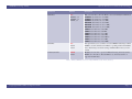
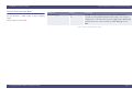
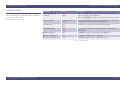
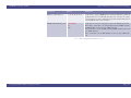
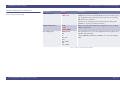
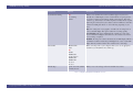
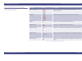
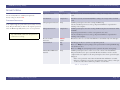
AMI BIOS Setup Utility
System Parameters and Standard Settings
AMIBIOS® Setup Utility
System Parameters and Standard Settings
Modifications to the BIOS Setup settings should be performed by advanced users
only. Setting items to incorrect values may cause your system to malfunction.
AMIBIOS Setup Utility, version MS1421 & MS164x, 06/2007
Copyright 2007 NEC Computers SAS
Introducing BIOS Setup.........................2
Main Menu.............................................4
Advanced Menu...................................10
Power Manager Menu..........................17
Security Menu......................................18
Boot Menu ...........................................20
Exit Menu ............................................22
AMIBIOS® is a registered trademark of American Megatrends Inc.
Page 1
AMI BIOS Setup Utility
INTRODUCING BIOS SETUP
Your computer comes with a hardware configuration program called BIOS Setup that allows you to view
and set system parameters.
The BIOS (Basic Input/Output System) is a layer of software, called ‘firmware’, that translates instructions
from software (such as the operating system) into instructions that the computer hardware can understand.
The BIOS settings also identify installed devices and establish special features.
USE BIOS SETUP TO:
• set the current time and date,
• customise your hardware settings according to your needs,
• secure your computer with a password.
System Parameters and Standard Settings
LOOKING AT SCREENS
BIOS setup screens have three areas:
• Menu items - the top of the screen. This area highlights which menu is active.
• Parameters - the left side of the screen. This area lists parameters and their current settings.
• Available Options and Help - the right side of the screen. This area lists alternate settings and Help
text for each parameter.
Options that are greyed out are not available for the current selection. Settings displayed in blue are
automatically detected by your computer.
USING KEYS
The following table lists the BIOS Setup keys and their functions:
Key
ENTERING BIOS SETUP
You can access the BIOS program just after you turn on your computer. Just press the F2 key when the
following prompt appears:
Press <F2> to enter Setup.
When you press F2 to enter BIOS Setup, the system interrupts the Power-On Self-Test (POST).
If the system detects an error during POST, it prompts you with a double beep and a message: Press <F1>
to resume. If you press F1, the system enters the BIOS Setup program. If you want to fix the error, carefully
read the error message that appears above the prompt (taking notes if you want) and press F2.
Note: if you receive this message repeatedly and the date displayed by your computer is inaccurate,
then your CMOS battery may have lost charge. Contact your Technical Support Centre for advice.
F1
Displays a general help screen
Í&Î
Moves between the available menus.
Ï&Ð
Moves the cursor between the displayed parameters.
Enter
Selects a sub-menu (sub-menus are indicated with a ¾ at the beginning of the
line), a menu command (such as Exit Discarding Changes), or displays the options
available for the currently selected parameter.
+&-
Steps forward/backward through the settings available for the selected parameter.
Tab
For some parameter settings, moves the cursor between the subfields. For
example, for System Time, Tab moves the cursor from hour to minute to second.
Esc
Exits any pop-up window, and from any menu screen, prompts for the discarding
of changes before exiting.
F9
Loads the default configurations, as recorded before the computer left the factory.
F10
Saves and exits the BIOS setup utility.
BIOS SETUP SCREENS
After you press F2, the system displays the BIOS Setup interface. Use the left and right arrow keys to
toggle through the BIOS Setup menu items.
Copyright 2007 NEC Computers SAS
Function
Table 1: BIOS Setup Keys and Associated Functions
Page 2
AMI BIOS Setup Utility
System Parameters and Standard Settings
SETUP MENUS
The Setup Utility features several menus which are listed on the menu bar at the top of the screen.
Main - use this menu for basic system configuration.
Advanced - use this menu to set ATA/IDE configuration, I/0 device configuration and more.
Power Manager - use this menu to enable or disable controllers or define suspend modes.
Security - use this menu to set user and administrator passwords, or the hard disk drive password.
Boot - use this menu to set the boot sequence.
Exit - use this menu to exit the Setup utility with various save or discard options.
These menus are described in detail in the following pages.
Note: we continually strive to bring you the latest and proven features and technologies. As part of our
drive to continually improve our products modifications may have been made to the BIOS menus,
therefore some menus may differ from what is described in this guide. Visit our web site at
www.nec-computers.com for updated information.
Copyright 2007 NEC Computers SAS
Page 3
AMI BIOS Setup Utility
MAIN MENU
Use the Main menu screen to view and/or modify system time,
system date and drive parameters.
Factory settings are shown in red.
System Parameters and Standard Settings
Parameter
Options
Description
Market Name
This field is read-only Displays your notebook’s market name.
and cannot be changed
from the BIOS Setup.
Model Name
This field is read-only Displays your notebook model name.
and cannot be changed
from the BIOS Setup.
System Date
mm/dd/yyyy
Sets your system's calendar month, day and year. These settings remain in
memory even after you turn off system power.
To set the date use the Tab or Enter keys to move from field to field. Simply type
the new number required.
System Time
hh/mm/ss
Sets the time. Enter the current hour, minute and second in hr/min/sec, 24-hour
format.
To set the time use the Tab or Enter keys to move from field to field. Simply type
the new number required.
X Primary IDE Master
[Hard Disk]
Pressing Enter displays information about the hard disk drive.
X Secondary IDE Master
[Type of secondary IDE Pressing Enter displays information about the secondary IDE device installed, if
device installed.
any.
Example ATAPI
CDROM]
X Trusted Computing
[Enter]
Press Enter if you want to modify settings related to the optional Trusted
Platform Module.
X USB Configuration
[Enter]
Press Enter for configuring the USB support.
X System Information
[Enter]
Pressing Enter displays information about your system like firmware, processor or
memory information.
Table 2: Main Menu
Copyright 2007 NEC Computers SAS
Page 4
AMI BIOS Setup Utility
PRIMARY IDE MASTER AND SECONDARY IDE
MASTER SUB-MENUS
Use this sub-menu to modify drive parameters and related settings.
Factory settings are shown in red
Drive Parameters
The greyed-out items in the upper frame of the sub-menu are the
IDE drive parameters taken from the firmware of the IDE drive
selected. Depending on the type of device detected, all options
shown in the beside table may not be displayed.
.
System Parameters and Standard Settings
Parameter
Options
Description
Device
This field is read-only.
Type of device, e.g. hard disk drive
Vendor
This field is read-only.
Manufacturer of the device
Size
This field is read-only.
Size of the device
LBA Mode
This field is read-only.
LBA (Logical Block Addressing) is a method of addressing data on a disk drive.
Block Mode
This field is read-only.
Block mode boosts IDE drive performance by increasing the amount of data
transferred.
PIO Mode
This field is read-only.
IDE PIO mode programs timing cycles between the IDE drive and the
programmable IDE controller. As the PIO mode increases, the cycle time
decreases.
Async DMA
This field is read-only.
Indicates the highest Asynchronous DMA Mode that is supported.
Ultra DMA
This field is read-only.
Indicates the highest Synchronous DMA Mode that is supported.
S.M.A.R.T.
This field is read-only.
SMART is a feature which alerts the BIOS to a possible problem with and IDE
device.
Type
Not installed
Auto
CD/DVD
ARMD
This option sets the type of device that the AMIBIOS attempts to boot from after
the Power-On Self-Test (POST) has completed.
Not Installed : select this value to prevent the BIOS from searching for an IDE
disk drive on the specified channel.
Auto : select this value to allow the BIOS to detect automatically the IDE drive
type attached to the specified channel. This setting should be used if an IDE hard
disk drive is attached to the specified channel.
CD/DVD: this option specifies that an IDE optical disk drive is attached to the
specified IDE channel. The BIOS will not attempt to search for other types of
IDE drives on the specified channel.
ARMD: this option specifies an ATAPI Removable Media Device. This includes,
but is not limited to ZIP or LS-120.
Table 3: Primary IDE Master and Secondary IDE Master Sub-menus
Copyright 2007 NEC Computers SAS
Page 5
AMI BIOS Setup Utility
System Parameters and Standard Settings
Parameter
Options
Description
LBA/Large Mode
Disabled
Auto
LBA (Logical Block Addressing) is a method of addressing data on a disk drive.
Disable: set this value to prevent the BIOS from using Large Block Addressing
mode control on the specified channel.
Auto: set this value to allow the BIOS to auto detect the Large Block Addressing
mode control on the specified channel.
Block (Multi-Sector Transfer)
Disabled
Auto
This option sets the block mode multi sector transfers option.
Disabled: set this value to prevent the BIOS from using Multi-Sector Transfer on
the specified channel. It forces your IDE controller to transfer only a single sector
(512 bytes) per interrupt, thus degrading performance.
Auto: this option allows your IDE controller to transfer as many sectors per
interrupt as the hard disk is able to support. Refer to the Block Mode
information field above to get this information.
PIO Mode
Auto
0
1
2
3
4
IDE PIO (Programmable I/O) mode defines timing cycles between the IDE
drive and the programmable IDE controller.
Auto: select this value to allow the BIOS to detect automatically the PIO mode.
0: data transfer rate of 3.3 MBs.
1: data transfer rate of 5.2 MBs.
2: data transfer rate of 8.3 MBs.
3: data transfer rate of 11.1 MBs.
4: data transfer rate of 16.6 MBs.
Table 3: Primary IDE Master and Secondary IDE Master Sub-menus (Continued)
Copyright 2007 NEC Computers SAS
Page 6
AMI BIOS Setup Utility
System Parameters and Standard Settings
Parameter
Options
Description
DMA Mode
Auto
SWDMA0, 1, 2
MWDMA, 1, 2
UDMA0, 1, 6
Auto: select this value to allow the BIOS to detect automatically the DMA mode.
SWDMA0: data transfer rate of 2.1 MBs.
SWDMA1: data transfer rate of 4.2 MBs.
SWDMA2: data transfer rate of 8.3 MBs.
MWDMA0: data transfer rate of 4.2 MBs.
MWDMA1: data transfer rate of 13.3 MBs.
MWDMA2: data transfer rate of 16.6 MBs.
UDMA0: data transfer rate of 16.6 MBs.
UDMA1: data transfer rate of 25 MBs.
UDMA2: data transfer rate of 33.3 MBs.
UDMA3: data transfer rate of 44.4 MBs.
UDMA4: data transfer rate of 66.6 MBs. T
UDMA5: data transfer rate of 99.9 MBs.
UDMA6: data transfer rate of 133.2 MBs.
S.M.A.R.T.
Auto
Disabled
Enabled
This option allows you to set whether or not the SMART monitoring is enabled.
SMART is a feature which alerts the BIOS to a possible problem with and IDE
device. After having received this warning, the BIOS will then alert you to the
problem.
32-bit Data Transfer
Enabled
Disabled
Disabled: select this value to prevent the BIOS from using 32-bit data transfers.
Enabled: select this value to allow the BIOS to use 32-bit data transfers on
supported hard disk drives.
Table 3: Primary IDE Master and Secondary IDE Master Sub-menus (Continued)
Copyright 2007 NEC Computers SAS
Page 7
AMI BIOS Setup Utility
TRUSTED COMPUTING SUB-MENU
Use this sub-menu to modify settings of trusted computing
features.
Factory settings are shown in red.
System Parameters and Standard Settings
Parameter
Options
Description
TCG/TPM Support
No
Yes.
The TPM is a distinct component on the computer motherboard that is
responsible for storing platform information that is unique to that computer’s
configuration in a secure manner.If your system is equipped with a TPM module,
this option allows you to activate/deactivate the TCG/TPM support in the
BIOS.
Table 4: Trusted Computing Sub-Menu
Copyright 2007 NEC Computers SAS
Page 8
AMI BIOS Setup Utility
USB CONFIGURATION SUB-MENU
Use this sub-menu to modify the USB configuration.
Factory settings are shown in red.
System Parameters and Standard Settings
Parameter
Options
Description
Legacy USB Support
Enabled
Disabled
Auto
Legacy USB Support refers to the USB mouse and USB keyboard support. When
this option is not enabled, any attached USB mouse or USB keyboard will not
work until a USB compatible operating system is fully booted with all USB
drivers loaded. When this option is enabled, any attached USB mouse or USB
keyboard can control the system even when there is no USB drivers loaded on
the system.
Disabled: set this value to prevent the use of any USB device in DOS or during
system boot.
Enabled: set this value to allow the use of USB devices during boot and while
using DOS.
Auto: this option detects automatically USB keyboards or mice and if found,
allows them to be used during boot and while using DOS.
USB 2.0 Controller Mode
FullSpeed
HiSpeed
Allows you to configure the USB 2.0 controller in HiSpeed (480 Mbps) or
FullSpeed (12 Mbps).
Hotplug USB FDD support
Disabled
Enabled
Auto
Allows you to enable or disable the support for a USB floppy disk drive. When set
to auto, the system automatically detects the device and enables the support for
the device.
Table 5: USB configuration Sub-Menu
Copyright 2007 NEC Computers SAS
Page 9
AMI BIOS Setup Utility
ADVANCED MENU
Use the Advanced menu to define IDE or chipset configuration,
or set options for the I/O ports.
Factory settings are shown in red.
System Parameters and Standard Settings
-
Parameter
Options
Description
Intel(R) SpeedStep(TM)
Technology
Enabled
Disabled
When set to Enabled, the system performs at the optimised performance set
under the operating system (if applicable).
When set to Disabled, the system preserves as much battery power as possible.
PCI Latency Timer
32, 64, 96, 128, 160, 192,
224, 248
Increasing the PCI latency timer gives the PCI bus more time to transfer data
across the PCI bus, which can lead to better performance.
System Keyboard
Absent
Present
Set this option to select whether a system keyboard is available.
Intel(R)AMT Support
Enabled
Disabled
For computers featuring this technology: allows you to enable/disable the
IAMT support.
X IDE Configuration
[Enter]
Press Enter if you want to modify settings of the IDE devices.
X Chipset Configuration
[Enter]
Press Enter for modifying chipset configuration.
X Advanced PCI/PnP Settings [[Enter]
Press Enter to display options for configuring I/O ports.
Table 6: Advanced Menu
Copyright 2007 NEC Computers SAS
Page 10
AMI BIOS Setup Utility
IDE CONFIGURATION SUB-MENU
Factory settings are shown in red.
System Parameters and Standard Settings
-
Parameter
Options
Description
ATA/IDE Configuration
Disabled
Compatible
Enhanced
Specifies the integrated IDE controller.
Disabled disables the integrated IDE controller.
Compatible enables up to two IDE channels for operating systems requiring
legacy IDE operation.
Enhanced enables all SATA and PATA resources.
Configure SATA as
IDE
RAID
AHCI
This option is displayed when the ATA/IDE Configuration option is set to
Enhanced.
The SATA controller has three modes of operation:
IDE mode - no AHCI, no RAID
AHCI mode - AHCI enabled, no RAID
RAID mode - AHCI enabled, RAID enabled
WARNING: Switching SATA modes in the BIOS after installing the operating
system is not recommended or supported when a SATA drive is the boot drive. Switching modes may cause an immediate blue screen, followed by a reboot.
Legacy IDE Channels
SATA only
STA pri, PAT sec
PATA only
This option is displayed when the ATA/IDE Configuration option is set to
Compatible.
Configures PATA and SATA resources for operating systems requiring legacy
IDE operation.
X Primary IDE Master
[Hard Disk]
Refer to “Primary IDE Master and Secondary IDE Master Sub-Menus” on
page 5.
X Secondary IDE Master
[Type of secondary IDE
device installed. Example
ATAPI CDROM]
Refer to “Primary IDE Master and Secondary IDE Master Sub-Menus” on
page 5
Hard Disk Write Protect
Disabled
Enabled
Disabled: set this value to allow the hard disk drive to be used normally. Read,
write, and erase functions can be performed to the hard disk drive.
Enabled: set this value to prevent the hard disk drive from being erased.
Table 7: IDE Configuration Sub-Menu
Copyright 2007 NEC Computers SAS
Page 11
AMI BIOS Setup Utility
System Parameters and Standard Settings
Parameter
Options
Description
IDE Detect Time Out (sec.)
0, 5, 10, 15, 20, 25, 30, 35
Set this option to stop the AMIBIOS from searching for IDE devices within the
specified number of seconds. Basically, this allows you to fine-tune the settings
to allow for faster boot times. Adjust this setting until a suitable timing that can
detect all IDE disk drives attached is found.
ATA(PI) 80Pin Cable Detection Host & Device
Host
Device
Set this option to select the method used to detect the ATA (PI) 80 pin cable.
Host & Device: set this value to use both motherboard onboard IDE controller
and IDE disk drive to detect the type of IDE cable used.
Host: set this value to use the motherboard onboard IDE controller to detect the
type of IDE cable used.
Device: set this value to use the IDE disk drive to detect the type of IDE cable
used.
Table 7: IDE Configuration Sub-Menu (Continued)
Copyright 2007 NEC Computers SAS
Page 12
AMI BIOS Setup Utility
CHIPSET CONFIGURATION SUB-MENU
Factory settings are shown in red.
System Parameters and Standard Settings
-
Parameter
Options
Description
DVMT Mode Select
Fixed mode
DVMT mode
Dynamic Video Memory Technology
DVMT mode is memory that is dynamically allocated based on memory requests
made by application and are released back to the system once the requesting
application has been terminated.
Fixed mode is non-contiguous page locked memory allocated during driver
initialization to provide a static amount of memory.
DVMT/FIXED Memory
128 MB
256 MB
Maximum DVMT
Allows you to select the maximum amount of graphics memory to be shared
with the system memory.
Boot Display Device
VBIOS-Default
CRT
TV
CRT + TV
SDVO
CRT + SDVO
LVDS
CRT + LVDS
This option allows you to set the video display that the internal graphics device
will enable during the POST.
Selecting VBIOS Default will allow the VBIOS to choose the video display to
enable.
Table 8: Chipset Configuration Sub-Menu
Copyright 2007 NEC Computers SAS
Page 13
AMI BIOS Setup Utility
System Parameters and Standard Settings
Parameter
Options
Description
Local Flat Panel Scaling
Auto
Forced Scaling
Disabled
Allows you to determine how various resolutions appear on your screen.
Basically since an LCD display consists of a fixed number of separate pixels, it
has a 'native' resolution at which images display at their sharpest. This native
resolution (e.g. 1280x1024) is the number of pixels in width x number of pixels
high in the panel, and any time your software resolution is different to this native
resolution the LCD panel will do one of the following depending on your
choice:
Auto: The scaling unit on your graphics card will rescale the image before it
reaches your LCD display. This option results in the best image quality.
Forced Scaling: This option will maintain the original aspect ratio of the
chosen resolution and display it with black bars to the sides/above/below the
on-screen image as required.
Disabled- The image isn't scaled at all, but instead your LCD display will run at
its maximum resolution and the image will display in the centre of your LCD
display. This may result in a black border around the sides of the image.
TV Standard
VBIOS-Default
NTSC
PAL
SECAM
SMPTE240M
ITU-R television
SMPTE295M
SMPTE296M
EIA-770.2
EIA-770.3
When connecting a TV to your computer, allows you to set the appropriate
standard for your TV (PAL for most of Europe).
TV Sub-Type
depends on the TV standard
previously selected.
Allows you to set the sub-type of the TV standard selected above.
Table 8: Chipset Configuration Sub-Menu (Continued)
Copyright 2007 NEC Computers SAS
Page 14
AMI BIOS Setup Utility
System Parameters and Standard Settings
Parameter
Options
Description
BootBlock HECI Message
Disabled
Enabled
Do not modify these options unless you are an advanced user.
HECI Message
Disabled
Enabled
End of Post S5 HECI Message
Disabled
Enabled
Table 8: Chipset Configuration Sub-Menu (Continued)
Copyright 2007 NEC Computers SAS
Page 15
AMI BIOS Setup Utility
ADVANCED PCI/PNP SETTINGS SUB-MENU
Factory settings are shown in red.
System Parameters and Standard Settings
-
Parameter
Options
Description
Serial Port 1 Address
Disabled
3F8/IRQ4
3E8/IRQ4
2E8/IRQ3
Allows you to set the address and interrupt request for serial port 1 on the
optional port replicator.
IR Address
Disabled
3F8/IRQ4
2F8/IRQ3
3E8/IRQ4
2E8/IRQ3
Allows you to set the address and interrupt request for the infrared port.
IR Mode
FIR
SIR
Allows you to set the infrared mode for the infrared port.
IR DMA Channel
DMA 1
DMA 3
Allows you to set the DMA channel for the infrared port.
Parallel Port Address
Disabled
378
278
3BC
Allows you to set the address for the parallel port on the optional port replicator.
Parallel Port Mode
SPP
Bi-directional
EPP
ECP
Allows you to set the mode for the parallel port on the optional port replicator.
Parallel Port IRQ
IRQ5
IRQ7
Allows you to set the interrupt request for the parallel port on the optional port
replicator.
Table 9: Advanced PCI/PnP Settings Sub-Menu
Copyright 2007 NEC Computers SAS
Page 16
AMI BIOS Setup Utility
POWER MANAGER MENU
Use the Power Manager menu to define settings related to power
management.
Factory settings are shown in red.
System Parameters and Standard Settings
-
Parameter
Options
Description
ACPI Standby State
S1 (POS)
S3 (STR)
Auto
Sets the ACPI Standby State when system goes into ACPI Standby Mode.
S1/PSOS: Power on Suspend. In the S1 state, a bit more power is consumed
and the fans remain active.
S3/STR: Suspend to RAM. Provides the greatest amount of power savings.
While in the S3 state, the PC is silent with the monitor and fans off.
Repost Video on S3 Resume
No
Yes
Set this value to allow video repost support.
No: this setting prevents the video BIOS to be initialized when coming out of
the S3 state.
Yes: this setting allows the video BIOS to be initialized when coming out of the
S3 state.
GbE Controller
Enabled
Disabled
Allows you to enable or disable the LAN controller.
GbE LAN Boot
Enabled
Disabled
Allows you to enable or disable boot over the network.
GbE Wake up from S5
Enabled
Disabled
Allows you to enable or disable remote wake-up when the system is powered
off.
HDA Controller
Enabled
Disabled
Allows you to enable or disable the HDA (High Definition Audio) controller.
1394 Device
Enabled
Disabled
Enables or disables the onboard IEEE 1394.
Table 10: Power Manager Menu
Copyright 2007 NEC Computers SAS
Page 17
AMI BIOS Setup Utility
SECURITY MENU
Use the Security Menu to establish system passwords:
Factory settings are shown in red.
System Parameters and Standard Settings
Parameter
Options
Description
Supervisor Password
Example: Clear
This field is read-only and automatically filled according to the changes made to the fields
below.
User Password
Example: Clear
This field is read-only and automatically filled according to the changes made to the fields
below.
PASSWORD PROTECTION
Your computer supports a password for system security on several
levels. Keep in mind that you must set the supervisor password
before the BIOS Setup utility allows you to set a user password.
.
Change Supervisor Password [Enter]
Establishes password protection when entering the BIOS setup.
If the Password Check option is set to Always, this password will also be requested when
switching on the computer.
Change User Password
Example: Clear
Establishes password protection when entering the BIOS setup but some menu items will be
unavailable.
A supervisor password must be set before a user password can be used.
If the Password Check option is set to Always, this password will also be requested when
switching on the computer.
Boot Sector Virus
Protection
Disabled
Enabled
Write Protect the boot sector of the hard disk drive to avoid infection by some virus types.
Password Check
Setup
Always
This field appears only once you have set a supervisor password.
When set to Always, the system prompts you for a password when entering the BIOS setup,
and each time you boot.
When set to Setup, the system prompts you for a password only when entering Setup.
Primary Master HDD User [Enter]
Password
Establishes password protection to restrict access to the contents of the hard disk drive.
This password allows you to protect your hard disk drive should it be moved to another
computer. If the new computer uses the same password protection scheme a password request
will appear:
• If the correct password is entered then the hard disk drive will function as normal.
• If the new computer does not use the same password protection scheme, or if the password is not entered then it will not be possible to access the drive.
Note: when entering BIOS Setup using the user password,
only a limited number of fields can be changed; the most
sensitive items are read-only.
Table 11: Security Menu
Copyright 2007 NEC Computers SAS
Page 18
AMI BIOS Setup Utility
ESTABLISHING PASSWORDS
Note: for more information on security features (hardware and operating system passwords), please refer to
the '"Protecting your Notebook' section of the Online Documentation. You will find information on how
to setup Windows® and network passwords, as well as passwords to resume from Standby mode or from
the screensaver.
System Parameters and Standard Settings
Changing an Hard Disk Drive Password
1. In the BIOS Setup, select the Security menu.
2. Select Primary Master HDD User Password and press Enter.
Note: if the option Primary Master HDD User Password is greyed out, you cannot modify it: shut
down your computer using the power button, then restart it and enter the BIOS Setup.
3. Type the new password and press Enter.
BIOS SETUP AND BOOT PASSWORDS
To establish password protection for entering the BIOS Setup utility or accessing the computer at start up,
you must set the supervisor password before setting a user password.
• To enter a password simply select Change Supervisor Password, type the password of your
choice, press Enter, re-enter the password to confirm, press Enter again, and when prompted,
press Enter to continue. Click on Change User Password and repeat this procedure to set the
user password.
HARD DISK DRIVE PASSWORD
Your computer allows you to establish password protection for the internal hard disk drive. This
protection restricts access to the drive when installed in your computer but also when if the drive is
removed from your computer is installed in another system.
The HDD password is written to the system BIOS and to the hard disk drive to ensure that the password
protection travels with the drive when moved from system to system.
Note: if you do not wish to establish another password, press Enter without entering any value in theses
fields.
4. Type it again to confirm, and press Enter. When the Password installed notice pops up, press Enter
to continue.
5. Press F10 to save changes and exit BIOS Setup.
Moving the Hard Disk Drive
When a password-protected hard disk drive is moved from its original system and installed in another
system, error messages appear indicating that the drive is locked. If the system is equipped with the same
hard disk drive password protection feature, a Security Setup window will pop up, requiring the user to
enter the password to unlock the drive.
If you wish to move a hard disk drive from one system to another, make sure to clear the hard disk drive
password before you do so.
Establishing an Hard Disk Drive Password
1. In the BIOS Setup, select the Security menu.
2. Select Primary Master HDD User Password and press Enter.
3. Type the password of your choice and press Enter.
4. Type it again to confirm, and press Enter.When the Password installed notice pops up, press Enter
to continue.
5. Press F10 to save changes and exit BIOS Setup.
Copyright 2007 NEC Computers SAS
Page 19
AMI BIOS Setup Utility
BOOT MENU
Use this menu to modify the boot options, and to specify the order
of the bootable devices.
System Parameters and Standard Settings
Parameter
Options
Description
Quick Boot
Disabled
Enabled
Allows BIOS to skip some tests while booting. When Enabled is set, the time needed to
boot the system is decreased.
Internal TouchPad Support
Disabled
Enabled
Auto
Allows you to enable or disable the support for the internal touchpad. When set to auto, the
system automatically detects the device and enables the support for the device.
Full Screen Logo Display
Disabled
Enabled
When set to Enabled, the logo screen appears during boot.
When set to Disabled, the POST messages appear during boot.
Boot-Up Num Lock
Off
On
Sets the Num Lock status when the system boots up.
Wait for F1 if error
Enabled
Disabled
Disabled: this prevents to wait on an error for user intervention. This setting should be used
if there is a known reason for a BIOS error to appear. An example would be a system
administrator must remotely boot the system. The computer system does not have a
keyboard currently attached. If this setting is set, the system will continue to boot up in to
the operating system. If ‘F1’ is enabled, the system will wait until the BIOS setup is entered.
Enabled: set this value to allow the system BIOS to wait for any error. If an error is detected,
pressing <F1> will enter Setup and the BIOS setting can be adjusted to fix the problem.
Hit «Del» Message Display
Enabled
Disabled
This prevents to display «Hit Del to enter Setup» during memory initialization.
1st Boot Device
USB: USB
Hotplug FDD
CD/DVD
SATA
Network
Disabled
Sets the primary boot device.
BOOT ORDER
The entries from this field represent devices that can be used to
start your computer. When your computer starts it will search
each device, following the order defined in the list, for any 'boot'
(start-up) instructions available. If a disk is found that contains
such information, it will be used to start your computer.
This can be useful if the disk contains a 'rescue' program, that will
solve a serious problem with your computer (your Recovery Disk
or Recovery CD does this). Consequently, you should keep
removable devices above your main hard drive in this list. Should
your computer's hard drive develop a major fault, you will also be
able to use a bootable CD or floppy disk to start your computer.
QUICK ACCESS TO BOOT ORDER PRIORITY MENU
The boot order priority menu can be accessed when starting the
computer. Press the F8 key when the following prompt appears:
«Press F8 key to run boot menu».
In the menu displayed, select the device from which you want to
boot and press Enter.
Table 12: Boot Menu
BOOTING FROM THE NETWORK
Press the F12 key when the following prompt appears: «Press F12
key for LAN Boot.»
Copyright 2007 NEC Computers SAS
Page 20
AMI BIOS Setup Utility
System Parameters and Standard Settings
Parameter
Options
Description
2nd Boot Device
USB: USB Hotplug Sets the secondary boot device.
FDD
CD/DVD
SATA
Network
Disabled
3rd Boot Device
USB: USB Hotplug Sets the third boot device.
FDD
CD/DVD
SATA
Network
Disabled
4th Boot Device
USB: USB Hotplug Sets the fourth boot device.
FDD
CD/DVD
SATA
Network
Disabled
Table 12: Boot Menu (Continued)
Copyright 2007 NEC Computers SAS
Page 21
AMI BIOS Setup Utility
EXIT MENU
Use this menu to implement or discard the changes you made to
the BIOS Setup, and/or to exit the utility. Select any parameter
and press Enter to perform the corresponding action.
Note: you will always be prompted for confirmation.
System Parameters and Standard Settings
Parameter
Description
Save changes and Exit
Accepts changes made to current settings, and exits BIOS Setup.
Discard Changes and Exit
Exits Setup without applying any changes that have been made during this session.
Discard Changes
Reverses any changes that have been made during this session.
Load Optimal Defaults
Loads default configuration settings that were defined before the computer left the factory.
Table 13: Exit Menu
Copyright 2007 NEC Computers SAS
Page 22