1
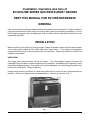
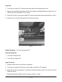
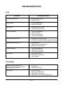
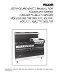
INSTALLATION &
OPERATION MANUAL
ECONOLINE SERIES GAS
RESTAURANT RANGES
MODEL
36L77R
60L77R
160L77R
260L77R
VULCAN-HART
ML-52113
ML-52114
ML-52115
ML-52116
COMPANY,
P.O.
BOX
FORM 30752 Rev. A (2-96) (Formerly 114583)
696,
LOUISVILLE,
KY
40201-0696,
TEL. (502) 7 7 8 - 2 7 9 1
IMPORTANT FOR YOUR SAFETY
THIS MANUAL HAS BEEN PREPARED FOR PERSONNEL QUALIFIED TO INSTALL GAS
EQUIPMENT, WHO SHOULD PERFORM THE INITIAL FIELD START-UP AND
ADJUSTMENTS OF THE EQUIPMENT COVERED BY THIS MANUAL.
POST IN A PROMINENT LOCATION THE INSTRUCTIONS TO BE FOLLOWED IN THE
EVENT THE SMELL OF GAS IS DETECTED. THIS INFORMATION CAN BE OBTAINED
FROM THE LOCAL GAS SUPPLIER.
IMPORTANT
IN THE EVENT A GAS ODOR IS DETECTED, SHUT
DOWN UNITS AT MAIN SHUTOFF VALVE AND
CONTACT THE LOCAL GAS COMPANY OR GAS
SUPPLIER FOR SERVICE.
FOR YOUR SAFETY
DO NOT STORE OR USE GASOLINE OR OTHER
FLAMMABLE VAPORS OR LIQUIDS IN THE
VICINITY OF THIS OR ANY OTHER APPLIANCE.
WARNING
IMPROPER INSTALLATION, ADJUSTMENT,
ALTERATION, SERVICE OR MAINTENANCE CAN
CAUSE PROPERTY DAMAGE, INJURY OR DEATH.
READ THE INSTALLATION, OPERATING AND
MAINTENANCE INSTRUCTIONS THOROUGHLY
BEFORE INSTALLING OR SERVICING THIS
EQUIPMENT.
IN THE EVENT OF A POWER FAILURE, DO NOT
ATTEMPT TO OPERATE THIS DEVICE.
—2—
TABLE OF CONTENTS
GENERAL. . . . . . . . . . . . . . . . . . . . . . . . . . . . . . . . . . . . . . . . . . . . . . . . . . . . . . . . . . . . . . . . . . . . . . 4
INSTALLATION . . . . . . . . . . . . . . . . . . . . . . . . . . . . . . . . . . . . . . . . . . . . . . . . . . . . . . . . . . . . . . . . . 4
Unpacking . . . . . . . . . . . . . . . . . . . . . . . . . . . . . . . . . . . . . . . . . . . . . . . . . . . . . . . . . . . . . . . . 4
Location . . . . . . . . . . . . . . . . . . . . . . . . . . . . . . . . . . . . . . . . . . . . . . . . . . . . . . . . . . . . . . . . . 5
Installation Codes and Standards . . . . . . . . . . . . . . . . . . . . . . . . . . . . . . . . . . . . . . . . . . . . . 5
Assembly . . . . . . . . . . . . . . . . . . . . . . . . . . . . . . . . . . . . . . . . . . . . . . . . . . . . . . . . . . . . . . . . 5
Ranges Mounted on Casters . . . . . . . . . . . . . . . . . . . . . . . . . . . . . . . . . . . . . . . . . . . 5
High Shelf . . . . . . . . . . . . . . . . . . . . . . . . . . . . . . . . . . . . . . . . . . . . . . . . . . . . . . . . . . 6
Broiler-Griddle Section . . . . . . . . . . . . . . . . . . . . . . . . . . . . . . . . . . . . . . . . . . . . . . . . 7
Conventional Griddles . . . . . . . . . . . . . . . . . . . . . . . . . . . . . . . . . . . . . . . . . . . . . . . . 8
Leveling . . . . . . . . . . . . . . . . . . . . . . . . . . . . . . . . . . . . . . . . . . . . . . . . . . . . . . . . . . . . . . . . . 9
Gas Connections . . . . . . . . . . . . . . . . . . . . . . . . . . . . . . . . . . . . . . . . . . . . . . . . . . . . . . . . . . 9
Testing the Gas Supply System . . . . . . . . . . . . . . . . . . . . . . . . . . . . . . . . . . . . . . . . . . . . . 10
Flue Connections . . . . . . . . . . . . . . . . . . . . . . . . . . . . . . . . . . . . . . . . . . . . . . . . . . . . . . . . . 10
Pilot Lighting Adjustments . . . . . . . . . . . . . . . . . . . . . . . . . . . . . . . . . . . . . . . . . . . . . . . . . . 11
Orifice Data . . . . . . . . . . . . . . . . . . . . . . . . . . . . . . . . . . . . . . . . . . . . . . . . . . . . . . . . . . . . . . 11
OPERATION . . . . . . . . . . . . . . . . . . . . . . . . . . . . . . . . . . . . . . . . . . . . . . . . . . . . . . . . . . . . . . . . . .
Controls . . . . . . . . . . . . . . . . . . . . . . . . . . . . . . . . . . . . . . . . . . . . . . . . . . . . . . . . . . . . . . . .
Lighting and Shutting Down Pilots . . . . . . . . . . . . . . . . . . . . . . . . . . . . . . . . . . . . . . . . . . .
Oven Pilot . . . . . . . . . . . . . . . . . . . . . . . . . . . . . . . . . . . . . . . . . . . . . . . . . . . . . . . . .
Open Top Pilots . . . . . . . . . . . . . . . . . . . . . . . . . . . . . . . . . . . . . . . . . . . . . . . . . . . .
Broiler/Griddle Pilot . . . . . . . . . . . . . . . . . . . . . . . . . . . . . . . . . . . . . . . . . . . . . . . . .
Before First Use . . . . . . . . . . . . . . . . . . . . . . . . . . . . . . . . . . . . . . . . . . . . . . . . . . . . . . . . . .
Rack Arrangements . . . . . . . . . . . . . . . . . . . . . . . . . . . . . . . . . . . . . . . . . . . . . . . . . . . . . . .
Oven Loading and Unloading . . . . . . . . . . . . . . . . . . . . . . . . . . . . . . . . . . . . . . . . . . . . . . .
Inserting and Removing Oven Rack . . . . . . . . . . . . . . . . . . . . . . . . . . . . . . . . . . . . . . . . . .
Preheating . . . . . . . . . . . . . . . . . . . . . . . . . . . . . . . . . . . . . . . . . . . . . . . . . . . . . . . . . . . . . .
Cleaning . . . . . . . . . . . . . . . . . . . . . . . . . . . . . . . . . . . . . . . . . . . . . . . . . . . . . . . . . . . . . . . .
Operating Suggestions . . . . . . . . . . . . . . . . . . . . . . . . . . . . . . . . . . . . . . . . . . . . . . . . . . . .
12
12
12
13
13
14
14
15
15
15
16
17
18
MAINTENANCE . . . . . . . . . . . . . . . . . . . . . . . . . . . . . . . . . . . . . . . . . . . . . . . . . . . . . . . . . . . . . . . . 19
Vent . . . . . . . . . . . . . . . . . . . . . . . . . . . . . . . . . . . . . . . . . . . . . . . . . . . . . . . . . . . . . . . . . . . . 19
Service and Parts Information . . . . . . . . . . . . . . . . . . . . . . . . . . . . . . . . . . . . . . . . . . . . . . . 19
TROUBLESHOOTING . . . . . . . . . . . . . . . . . . . . . . . . . . . . . . . . . . . . . . . . . . . . . . . . . . . . . . . . . . . 20
—3—
Installation, Operation and Care of
ECONOLINE SERIES GAS RESTAURANT RANGES
KEEP THIS MANUAL FOR FUTURE REFERENCE
GENERAL
Your Vulcan Econoline Range is produced with quality workmanship and material. Proper installation,
usage and maintenance of your range will result in many years of satisfactory performance. VulcanHart Company suggests that you thoroughly read this entire manual and carefully follow all of the
instructions provided.
INSTALLATION
Before installing, verify that the type of gas supply (natural or propane) agrees with the specifications
on the rating plate located on the inside lower front control cover. If the supply and equipment
requirements do not agree, do not proceed with the installation. Contact your dealer or Vulcan-Hart
Company immediately.
UNPACKING
This range was inspected before leaving the factory. The transportation company assumes full
responsibility for safe delivery upon acceptance of the shipment. Immediately after unpacking, check
for possible shipping damage. If the range is found to be damaged, save the packaging material and
contact the carrier within 15 days of delivery.
Uncrate range carefully and place in a work-accessible area as near to its final installed position as
possible. Remove all shipping wire and wood blocking. Remove accessories (Fig. 1).
Fig. 1
—4—
LOCATION
CAUTION: The equipment area must be kept free and clear of combustible substances.
The range, when installed, must have a minimum clearance from combustible and non-combustible
construction of 6" at the sides and 6" at the rear.
The installation location must allow adequate clearances for servicing and proper operation. A
minimum front clearance of 40" is required.
The range must be installed so that the flow of combustion and ventilation air will not be obstructed.
Adequate clearance for air openings into the combustion chamber must be provided. Make sure there
is an adequate supply of air in the room to allow for combustion of the gas at the burners.
INSTALLATION CODES AND STANDARDS
In the United States of America:
1. State and local codes.
2. National Fuel Gas Code, ANSI-Z223.1 (latest edition). Copies may be obtained from The American
Gas Association, Inc., 1515 Wilson Blvd., Arlington, VA 22209.
In Canada:
1. Local codes.
2. CAN/CGA-B149.1 Installation for Natural Gas Burning Appliances and Equipment (latest edition).
3. CAN/CGA-B149.2 Installation for Propane Burning Appliances and Equipment (latest edition).
Copies may be obtained from The Canadian Gas Association, 55 Scarsdale Road, Don Mills,
Ontario, Canada M3B2R3.
ASSEMBLY
Ranges Mounted on Casters
When ranges are mounted on casters, you must use a flexible connector (not supplied) that complies
with the Standard for Connectors of Movable Gas Appliances, ANSI-Z21.69 (latest edition), and a
quick-disconnect device that complies with the Standard for Quick-Disconnect Devices for Use With
Gas Fuel, ANSI Z21.41 (latest edition).
Provide a gas line strain relief to limit movement of the range without depending on the connector and/
or any quick-disconnect device or its associated piping to limit movement of the range. Attach the gas
line strain relief to the rear of the range (Fig. 2).
—5—
CONNECT GAS LINE
STRAIN
RELIEF HERE
PL-51219
Fig. 2
If it is necessary to disconnect the restraint, turn off the gas supply before disconnection. Reconnect
the restraint before turning the gas supply on and returning the range to its installation position.
High Shelf
The high shelf for this range is shipped as shown in Fig. 3 and is included in the range crate.
Fig. 3
With top cooking plates in their normal positions, assemble splasher back to range (Fig. 4), and fasten
in place with #10 sheet metal screws provided.
On 60, 160 and 260 ranges, use the center bracing angle.
Once splasher is secured in position, slide shelf into mounting brackets (Fig. 5). Shelf will lock into
position. No bolting is necessary. There is a decal located on the front of the range showing the proper
installation of the shelf to the splasher. Remove this decal once assembly is complete.
—6—
Fig. 4
Fig. 5
Broiler-Griddle Section
Vulcan Econoline Range Broilers are equipped with ceramic radiants for the most efficient operation.
These radiants are packed separately in the range oven. Proper installation positions of the radiants
are shown in Fig. 6.
Fig. 6
—7—
Conventional Griddles
Vulcan Econoline Ranges with conventional griddles have fire brick under the griddle section. The
bricks are packed separately in the range oven. Fig. 7 shows the proper installation positions.
All griddles have grease collectors which must be installed on the side of the range (Fig. 8).
Model 36FL77R Shown
Fig. 7
Griddle area shown with protective shipping solvent
Fig. 8
—8—
LEVELING
Check the leveling of the range. Place a carpenter's level inside the oven cavity across the oven rack.
Level the range from front to back and from side to side.
To adjust the leveling of the range, tilt the range to one side and, using channel locks, unscrew the
adjustable leg insert as required. Repeat this procedure as necessary for each leg.
Casters for this range are of the non-leveling type. Therefore, the floor must be level. If floor surface
is not level, the range will experience cooking problems until it is level.
GAS CONNECTIONS
CAUTION: All gas supply connections and any pipe joint compound used must be resistant to
the action of propane gases.
Each range is factory equipped for use with the type of gas specified on the range rating plate.
Connect gas supply to the range. Make sure the pipes are clean and free of obstructions.
Codes require that a gas shutoff valve be installed in the gas line ahead of the range.
Ranges are equipped with fixed burner orifices which coincide with the proper range operation
elevation.
The gas pressure regulator is NOT factory installed. The regulator for this range is sealed within a
plastic bag attached to the oven rack inside the oven. This regulator must be installed by qualified
personnel.
Before installing, check that the regulator matches the gas supply indicated on the data plate.
Natural gas regulators are preset for 3.5" W.C. (Water Column); propane gas regulators are preset for
10.0" W.C. (Water Column).
1. Locate 3/4" gas connection pipe extending from the rear of the range.
2. Cover pipe threads with pipe joint compound.
3. Screw regulator hand-tight onto the pipe with regulator arrow pointing towards range body back
(Fig. 9). The arrow on the regulator shows direction of gas flow.
4. Using pipe wrench, tighten regulator securely in an upright position (Fig. 10). The pressure
regulator must be mounted horizontally to ensure proper preset outlet pressure. If the regulator is
mounted in any other position, the outlet pressure must be reset.
The pressure regulator must be design certified and must have regulation capacity for the total
connected load. It must have a pressure adjustment range to allow adjustment for manifold pressure
marked on the range rating plate.
—9—
Fig. 9
Fig. 10
Unless manifold pressure on all connected appliances is the same, a separate regulator must be
supplied for all ranges having different manifold pressures.
A leak limiter is supplied with every regulator to allow excess gas pressure to escape. Do not obstruct
leak limiter on gas pressure regulator as obstruction may cause regulator to malfunction.
WARNING: PRIOR TO LIGHTING, CHECK ALL JOINTS IN THE GAS SUPPLY LINE FOR LEAKS.
USE SOAP AND WATER SOLUTION. DO NOT USE AN OPEN FLAME.
After piping has been checked for leaks, all piping receiving gas should be fully purged to remove air.
TESTING THE GAS SUPPLY SYSTEM
When gas supply pressure exceeds 1/2 psig (3.45 kPa), the range and its individual shutoff valve must
be disconnected from the gas supply piping system.
When gas supply pressure is 1/2 psig (3.45 kPa) or less, the range should be isolated from the gas
supply system by closing its individual manual shutoff valve.
FLUE CONNECTIONS
DO NOT obstruct the flow of flue gases from the flue duct located on the rear of the range. It is
recommended that the flue gases be ventilated to the outside of the building through a ventilation
system installed by qualified personnel.
From the termination of the range flue vent to the filters of the hood venting system, a minimum
clearance of 18" must be maintained.
— 10 —
Information on the construction and installation of ventilating hoods may be obtained from the standard
for "Vapor Removal from Cooking Equipment," NFPA No. 96 (latest edition), available from the
National Fire Protection Association, Batterymarch Park, Quincy, MA 02269.
Adequate air should be provided in the kitchen to replace air taken out by the ventilating system.
Do not permit fans to blow directly at the range. Whenever possible, avoid open windows next to the
range. Avoid wall-type fans which create air cross currents within the room.
PILOT LIGHTING ADJUSTMENTS
All adjustment procedures associated with pilot lighting must be performed by a qualified Vulcan-Hart
installation or service person. The bypass (minimum burner) flame adjustment must be made at the
time of installation.
ORIFICE DATA
OPEN TOP
GRIDDLE
BROILER
GRIDDLE
OVEN
15,000
15,000
10,000
35,000
NAT/PROP
NAT/PROP
NAT/PROP
NAT/PROP
SEA LEVEL TO 2000 FT.
48/57
48/57
54/62
34/51
2000 FT. TO 4000 FT.
49/57
49/58
56/65
38/52
4000 FT. TO 6000 FT.
50/58
50/60
56/66
39/53
6000 FT. TO 8000 FT.
51/59
51/63
57/67
39/54
INPUT AT SEA LEVEL
PER BURNER (BTU'S)
GAS TYPE
— 11 —
OPERATION
WARNING: THE RANGE AND ITS PARTS ARE HOT. BE VERY CAREFUL WHEN OPERATING,
CLEANING OR SERVICING THE RANGE.
The Econoline Range does not require special recipes. You may wish to use a temperature up to 25°F
higher or lower to obtain the particular product results that you prefer.
CONTROLS (Fig. 11)
Thermostat Dial
— Allows operator to regulate oven temperature from low to 500°F.
Open Top Burner Valve Knob — Regulates gas flow to top burners. Flame increases by turning
knob counterclockwise, and decreases by turning knob clockwise.
Griddle Burner Valve Knob
— Regulates gas flow to griddle burner. Heat increases by turning
knob counterclockwise, and decreases by turning knob clockwise.
GRIDDLE
BURNER VALVE
KNOB
THERMOSTAT DIAL
OPEN TOP
BURNER VALVE
KNOB
PL-40759-1
Fig. 11
LIGHTING AND SHUTTING DOWN PILOTS
All adjustment procedures associated with pilot lighting must be performed by a qualified Vulcan-Hart
installation or service person.
— 12 —
Oven Pilot
1. Turn main gas supply ON. Remove lower front panel and lift lighting hole cover.
2. Depress the reset button located behind the lower front panel and light pilot with a lit taper (Fig. 12).
Continue to hold reset button in for 1 minute.
3. If pilot fails to light, turn main gas supply OFF and wait 5 minutes before repeating Steps 1 and 2.
4. After pilot is lit, turn the thermostat dial to the desired setting.
Fig. 12
Nightly Shutdown: Turn oven thermostat OFF.
Extended Shutdown
1. Turn oven thermostat OFF.
2. Turn main gas supply OFF.
Open Top Pilots
1. Remove all top section cover plates and griddles.
2. Turn main gas supply ON (all burner valve knobs should be in OFF position).
3. Begin from the left range top side. Light each individual pilot from front to rear across the entire
range top section.
When lighting broiler/griddle section, the pilot is tubular in shape.
— 13 —
4. If any pilot fails to light or extinguishes, ensure that the burner valve knob is in the OFF position.
Wait 5 minutes, then relight.
5. After all pilots are lit, ensure that all burners are operational. To ignite burners, turn the burner valve
knobs fully ON, starting from left to right.
6. Turn burners OFF and reassemble top sections.
Nightly Shutdown: Turn burner valve knobs OFF.
Extended Shutdown
1. Turn burner valve knobs OFF.
2. Turn main gas supply OFF.
Broiler/Griddle Pilot
The broiler/griddle sections are operated by the same burners.
1. Turn main gas supply ON.
2. Remove the grid pan assembly and, using a taper, light the pilot from the underside of the griddle
where the grid pan assembly was removed.
3. If pilot fails to light, turn main gas supply OFF. Wait 5 minutes and repeat Steps 1 and 2.
Nightly Shutdown: Turn burner valve knobs OFF.
Extended Shutdown
1. Turn burner valve knobs OFF.
2. Turn main gas supply OFF.
BEFORE FIRST USE
Griddle Seasoning
This griddle plate is steel, but the surface is relatively soft and can be scored or dented by the careless
use of a spatula or scraper. Be careful not to dent, scratch, or gouge the plate surface. Do not try to
knock off loose food that may be on the spatula by tapping the corner edge of the spatula on the griddle
surface.
A new griddle surface must be seasoned to do a good cooking job. The metal surface of the griddle
is porous. Food tends to get trapped in these pores and stick; therefore, it is important to "season" or
"fill up" these pores with cooking oil before cooking. Seasoning gives the surface a slick, hard finish
from which the food will release easily.
— 14 —
To season, heat griddle top section at a low burner setting. Pour one ounce of cooking oil per square
foot of surface over the griddle top section. With an insulated cloth, spread the oil over the entire griddle
surface to create a thin film. Wipe off any excess oil with an insulated cloth.
Repeat this procedure 2 to 3 times until the griddle has a slick, mirrorlike surface.
RACK ARRANGEMENTS
The Econoline Series Oven is equipped with one rack per oven section. Each oven section has two
rack positions. Proper rack positioning is to be determined by the individual cooking needs of the
operator.
OVEN LOADING AND UNLOADING
When loading the oven, open the door and load as quickly as practical to conserve heat. Take care
to avoid spilling liquids while loading. Close the door and refer to recipe for cooking time.
Provide adequate space for product unloading. Rapid unloading will conserve heat and ensure proper
preheating conditions for the next load, if applicable.
INSERTING AND REMOVING OVEN RACK
On ovens provided with oven rack stops, it is necessary to place rack, including the support hook, along
the top of the side liner runners and slide the rack completely to the rear of the oven compartment until
the rack drops into place (Fig. 13).
Fig. 13
— 15 —
To remove the rack, reverse the procedure by raising the rear of the oven rack support hooks above
the runner and pulling the rack forward (Fig. 14).
Fig. 14
PREHEATING
Oven
Turn thermostat control to the desired cooking temperature and preheat oven for 25 minutes. The
automatic heat control will cut gas and food costs if properly used. Do not operate oven at maximum
heat when it is not necessary. Turn thermostat down to 250°F or OFF when oven is not in use or during
idle cooking periods.
Ranges (Open Top)
As these are quickly ignited, light only as many as needed.
Griddle Top Ranges
Heat top thoroughly before using. It can be kept hot with burners turned partly down. During off
periods, turn burners down or keep only half of top heated.
Broiler/Griddle Section
Before cooking on griddle plate, grease well and light burners. With minimum burner flame, allow
griddle to heat gradually. Do this the first three times the griddle is used. This will relieve stresses in
the plate and ensure long life.
— 16 —
1. Turn the three burner valve knobs fully ON.
2. After preheating for 5 minutes, turn the burner valve knobs down until the desired flame or heating
level is achieved.
3. Position removable grid into one of the two slide positions, depending on which will achieve the
proper product preparation results.
CLEANING
Ranges
Wipe top daily, while still warm, with a grease absorbing cloth to remove spillovers, grease, etc., before
they burn in. A crust on top of the range looks unsightly and slows down speed of cooking because
it reduces the flow of heat to the utensil. Scrape off if necessary.
Open Top Grates and Burners
Boil weekly in a solution of washing soda and water. Clean drip pan under burners with warm soapy
water. Rinse thoroughly and wipe dry with a soft clean cloth.
Griddle Top
Cleaning griddle and fry top sections will produce evenly cooked, perfectly browned griddle products
and will keep the cooking surface free from carbonized grease. Carbonized grease on the surface
hinders the transfer of heat to the food. This results in loss of cooking efficiency and spotty browning
which gives foods an unappetizing appearance. To keep the griddle clean and operating at peak
efficiency, follow these instructions:
After Each Use
Clean griddle with a wire brush or flexible spatula.
Once A Day
Thoroughly clean backsplash, sides and front. Remove grease pan, empty, and wash out in the
same manner as any ordinary cooking utensil.
Once A Week
Clean griddle surface thoroughly. If necessary, use a griddle stone, wire brush or steel wool over
surface. Rub with grain of the metal while still warm. A detergent may be used on the plate surface
to help clean it, but make sure it is thoroughly removed. After removal of detergent, reseason the
surface of the plate with a thin film of oil to prevent food sticking. If the griddle is to be shut down
for an extended period, put a heavy coat of grease over the griddle plate.
— 17 —
Oven
Clean oven and oven door daily, especially if fruit pies or tomato sauces were baked, meats roasted,
and if there have been spillovers.
Do not use scouring powder. It is extremely difficult to remove completely, and can build up
accumulations that will damage the oven.
Remove nickel plated racks and rack supports daily and clean in a sink.
After processing some foods at low temperatures, odors may linger in the oven. These odors may be
cleared by setting the thermostat at 500°F and allowing the oven to operate unloaded for 30 to 45
minutes.
Exterior
Clean exterior finish daily with a mild grease dissolving solution.
Painted surfaces may be cleaned using a cloth and detergent solution. Rinse thoroughly and wipe dry
with a soft clean cloth.
OPERATING SUGGESTIONS
Oven
If you desire to cook high roasts, the entire height of the oven can be used by removing shelf or rack
and placing roast pan directly on insulated oven bottom.
Moderate oven temperature will produce better food, reduce shrinkage and keep upkeep costs down.
Use low temperature roasting method with oven temperature at about 325°F to cut meat costs by
reducing shrinkage.
— 18 —
MAINTENANCE
WARNING: THE RANGE AND ITS PARTS ARE HOT. BE VERY CAREFUL WHEN OPERATING,
CLEANING OR SERVICING THE RANGE.
VENT
When cool, the vent of this range should be checked every six months for obstructions.
SERVICE AND PARTS INFORMATION
To obtain service and parts information concerning the ranges covered in this manual, contact the
Vulcan-Hart Service Agency in your area (refer to listing supplied with the range), or Vulcan-Hart
Company Service Department at the address or phone number shown on the front cover of this manual.
— 19 —
TROUBLESHOOTING
OVEN
PROBABLE CAUSES
PROBLEM
Too much bottom heat.
1. Insufficient heat input.
2. Overactive flue.
Uneven bake.
1. Too low temperature.
2. Improper operation.
Side burning.
1. Improper bypass setting.
2. Fluctuating gas pressure.
Too much top heat.
1.
2.
3.
4.
Uneven bake side-to-side.
1. Range not level side-to-side.
2. Oven burner, bottom or baffles improperly installed.
Uneven bake front-to-rear.
1. Overactive flue.
2. Range not level front-to-back.
3. Door not closing properly.
Dried out products.
1. Too low temperature.
2. Cooking time too long.
3. Thermostat calibration.
Pilot outage.
1. Pilot flame too low.
2. Restriction in pilot orifice.
3. Valve problem.
Too high temperature.
Faulty ventilation.
Excessive heat input.
Thermostat calibration.
TOP BURNER
Improper burner combustion;
excessive valve handle temperature;
sticking top burner valves.
1. Improper ventilation.
2. Poor door fit.
3. Oven door left open.
Poor ignition.
1.
2.
3.
4.
FORM 30752 Rev. A (2-96) (Formerly 114583)
Insufficient input.
Poor air-gas adjustment.
Restriction in pilot orifice.
Restriction in main burner ignition port.
— 20 —