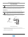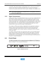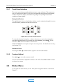
1
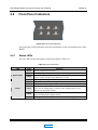
Model DP583 Frame Synchronizer User’s Manual Issue 1 MAIN Part Number 91793 Dolby Model DP583 Frame Synchronizer User’s Manual Dolby Laboratories, Inc. Corporate Headquarters Dolby Laboratories, Inc. 100 Potrero Avenue San Francisco, CA 94103-4813 Tel 415-558-0200 Fax 415-863-1373 www.dolby.com European Headquarters Dolby Laboratories Wootton Bassett Wiltshire, SN4 8QJ, England Tel (44) 1793-842100 Fax (44) 1793-842101 . DISCLAIMER OF WARRANTIES: Equipment manufactured by Dolby Laboratories is warranted against defects in materials and workmanship for a period of one year from the date of purchase. All warranties, conditions or other terms implied by statute are excluded to the fullest extent allowed by law. LIMITATION OF LIABILITY: It is understood and agreed that Dolby Laboratories’ liability whether in contract, in tort, under any warranty, in negligence or otherwise shall not exceed the cost of repair or replacement of the defective components and under no circumstances shall Dolby Laboratories be liable for incidental, special, direct, indirect or consequential damages (including but not limited to damage to software or recorded audio or visual material), or loss of use, revenue or profit even if Dolby Laboratories or its agents have been advised, orally or in writing, of the possibility of such damages. Dolby and the double-D symbol are registered trademarks and Pro Logic, Surround EX, and AC-3 are trademarks of Dolby Laboratories. All other trademarks remain the property of their respective owners. 2001 Dolby Laboratories, Inc. All rights reserved. S01/13991 Issue 1 Part Number 91793 ii MAIN Dolby Model DP583 Frame Synchronizer User’s Manual Table of Contents LIst of Figures ................................................................................................................v List of Tables................................................................................................................. vi Regulatory Notices ...................................................................................................... vii FCC .......................................................................................................... vii Canada..................................................................................................... vii UL............................................................................................................. vii UK ............................................................................................................ vii EU ........................................................................................................... viii Fuse Information............................................................................................................x Chapter 1 Introduction .......................................................................................... 1-1 Chapter 2 Setting Up ............................................................................................. 2-1 2.1 Unpacking.................................................................................... 2-1 2.2 System Considerations ................................................................ 2-1 2.2.1 Digital Input and Output ................................................... 2-1 2.2.2 Video Reference .............................................................. 2-1 2.2.3 Signal Characteristics ...................................................... 2-2 2.3 Front Panel .................................................................................. 2-2 2.3.1 Front-Panel Interface ....................................................... 2-3 2.3.2 Contrast Adjust ................................................................ 2-3 2.4 Status Menu................................................................................. 2-3 2.5 Setup Menu ................................................................................. 2-4 2.5.1 Selecting Parameters ...................................................... 2-4 2.5.2 Entering Text ................................................................... 2-5 2.6 Front-Panel Indicators ................................................................. 2-6 2.6.1 Status LEDs..................................................................... 2-6 2.6.2 Fault, Error, Supply LEDs ................................................ 2-7 2.7 Remote Connector....................................................................... 2-7 Chapter 3 Applications .......................................................................................... 3-1 3.1 Dolby E Distribution or Backhaul Application ............................... 3-1 3.2 Dolby E Post Production Application ........................................... 3-2 3.3 Dolby Digital (AC-3) Application................................................... 3-3 3.4 Additional Information .................................................................. 3-4 3.5 Alarms and Monitoring ................................................................. 3-4 Chapter 4 Front-Panel Menus ............................................................................... 4-1 4.1 Power On Key Functions ............................................................. 4-1 4.1.1 Setup ............................................................................... 4-1 4.1.2 Enter ................................................................................ 4-1 4.2 Status Displays ............................................................................ 4-2 iii MAIN Dolby Model DP583 Frame Synchronizer User’s Manual 4.3 Chapter 5 4.2.1 Main Status...................................................................... 4-2 4.2.2 Buffer Stats ...................................................................... 4-2 4.2.3 Error Stats........................................................................ 4-3 4.2.4 Other Status Menus......................................................... 4-3 Setup Menu ................................................................................. 4-4 4.3.1 Operating Mode ............................................................... 4-4 4.3.2 I/O Control ....................................................................... 4-5 4.3.3 System Settings............................................................... 4-5 Specifications ....................................................................................... 5-1 5.1 Connections................................................................................. 5-1 5.2 Electrical Specifications ............................................................... 5-1 5.2.1 Main Input ........................................................................ 5-1 5.2.2 Bypass Input .................................................................... 5-1 5.2.3 Main Output ..................................................................... 5-1 5.2.4 Video Reference Input ..................................................... 5-1 5.2.5 AES Ref ........................................................................... 5-2 5.2.6 Serial Remote Input ......................................................... 5-2 5.2.7 Status Port ....................................................................... 5-2 5.3 Power Requirements ................................................................... 5-3 5.4 Regulatory Notices ...................................................................... 5-3 5.5 Temperature and Humidity Specifications ................................... 5-4 5.6 Mechanical Specifications............................................................ 5-4 iv MAIN Dolby Model DP583 Frame Synchronizer User’s Manual List of Figures 2-1 2-2 2-3 3-1 3-2 3-3 3-4 3-5 5-1 5-2 5-3 DP583 Front Panel.......................................................................................... 2-2 Front-Panel Navigation Buttons ...................................................................... 2-3 Front-Panel Indicators..................................................................................... 2-6 Phase Aligned Dolby E Frames ...................................................................... 3-2 Non-Phase Aligned Dolby E Frames............................................................... 3-2 Post Production Application ............................................................................ 3-3 Cable Turn-Around Facility ............................................................................. 3-4 Hot-Standby Operation of the DP583 ............................................................. 3-5 DP583 Rear Panel .......................................................................................... 5-1 RS-232 Remote Connector............................................................................. 5-2 RS-485 Remote Connector............................................................................. 5-2 v MAIN Dolby Model DP583 Frame Synchronizer User’s Manual List of Tables 2-1 2-2 2-3 2-4 2-5 5-1 5-2 5-3 Status Menu Navigation Buttons..................................................................... 2-4 Setup Menu Navigation Buttons...................................................................... 2-4 Navigation in Text Entry Menu ........................................................................ 2-5 Front-Panel LEDs............................................................................................ 2-6 Status LED States........................................................................................... 2-7 RS-232 Remote Connector Pin-Outs .............................................................. 5-2 RS-485 Remote Connector Pin-Outs .............................................................. 5-2 Status Port Pin-Outs ....................................................................................... 5-3 vi MAIN Dolby Model DP583 Frame Synchronizer User’s Manual Regulatory Notices FCC This equipment has been tested and found to comply with the limits for a Class A digital device, pursuant to Part 15 of the FCC Rules. These limits are designed to provide reasonable protection against harmful interference when the equipment is operated in a commercial environment. This equipment generates, uses, and can radiate radio frequency energy and, if not installed and used in accordance with this instruction manual, may cause harmful interference to radio communications. Operation of this equipment in a residential area is likely to cause harmful interference in which case the user will be required to correct the interference at his or her own expense. Canada This Class A digital apparatus complies with Canadian ICES-003. UL Troubleshooting must be performed by a trained technician. Do not attempt to WARNING: service this equipment unless you are qualified to do so. Check that the correct fuses have been installed. To reduce the risk of fire, replace only with fuses of the same type and rating. This equipment has more than one power supply. To reduce the risk of electric shock, disconnect both power supply cords before servicing. Exposed portions of the power supply assembly are electrically "hot." In order to reduce the risk of electrical shock, the power cord MUST be disconnected when the power supply assembly is removed. The ground terminal of the power plug is connected directly to the chassis of the unit. For continued protection against electric shock, a correctly wired and grounded (earthed) threepin power outlet must be used. Do not use a ground-lifting adapter and never cut the ground pin on the three-prong plug. UK The power cord Dolby part 92021 supplied for use in Europe is not suitable for use in the UK. To use the cord in the UK cut off the CEE7/7 plug and replace with an approved BS 1363 13A plug: • The green and yellow cord must be connected to the terminal in the plug identified by the letter E or by the earth symbol or coloured green or green and yellow. • The blue cord must be connected to the terminal that is marked with the letter N or coloured black. The brown cord must be connected to the terminal that is marked with the letter L or coloured red. • This apparatus must be earthed. vii MAIN Dolby Model DP583 Frame Synchronizer User’s Manual EU This equipment complies with the EMC requirements of EN55103-1 and EN55103-2 when operated in an E2 environment in accordance with this manual. IMPORTANT SAFETY NOTICE This unit complies with the safety standard EN60065. The unit shall not be exposed to dripping or splashing and no objects filled with liquids, such as coffee cups, shall be placed on the equipment. To ensure safe operation and to guard against potential shock hazard or risk of fire, the following must be observed: o Ensure that your mains supply is in the correct range for the input power requirement of the unit. o Ensure fuses fitted are the correct rating and type as marked on the unit. o The unit must be earthed by connecting to a correctly wired and earthed power outlet. o The power cord supplied with this unit must be wired as follows: Live—Brown Neutral—Blue Earth—Green/Yellow GB IMPORTANT – NOTE DE SECURITE Ce materiel est conforme à la norme EN60065. Ne pas exposer cet appareil aux éclaboussures ou aux gouttes de liquide. Ne pas poser d'objets remplis de liquide, tels que des tasses de café, sur l'appareil. Pour vous assurer d'un fonctionnement sans danger et de prévenir tout choc électrique ou tout risque d'incendie, veillez à observer les recommandations suivantes. o Le selecteur de tension doit être placé sur la valeur correspondante à votre alimentation réseau. o Les fusibles doivent correspondre à la valeur indiquée sur le materiel. o Le materiel doit être correctement relié à la terre. o Le cordon secteur livré avec le materiel doit être cablé de la manière suivante: Phase—Brun Neutre—Bleu Terre—Vert/Jaune WICHTIGER SICHERHEITSHINWEIS Dieses Gerät entspricht der Sicherheitsnorm EN60065. Das Gerät darf nicht mit Füssigkeiten (Spritzwasser usw.) in Berührung kommen; stellen Sie keine Gefäße, z.B. Kaffeetassen, auf das Gerät. Für das sichere Funktionieren des Gerätes und zur Unfallverhütung (elektrischer Schlag, Feuer) sind die folgenden Regeln unbedingt einzuhalten: o Der Spannungswähler muß auf Ihre Netzspannung eingestellt sein. o Die Sicherungen müssen in Typ und Stromwert mit den Angaben auf dem Gerät übereinstimmen. o Die Erdung des Gerätes muß über eine geerdete Steckdose gewährleistet sein. o Das mitgelieferte Netzkabel muß wie folgt verdrahtet werden: Phase—braun Nulleiter—blau Erde—grün/gelb viii MAIN F D Dolby Model DP583 Frame Synchronizer User’s Manual NORME DI SICUREZZA – IMPORTANTE Questa apparecchiatura è stata costruita in accordo alle norme di sicurezza EN60065. Il prodotto non deve essere sottoposto a schizzi, spruzzi e gocciolamenti, e nessun tipo di oggetto riempito con liquidi, come ad esempio tazze di caffè, deve essere appoggiato sul dispositivo. Per una perfetta sicurezza ed al fine di evitare eventuali rischi di scossa êlettrica o d'incendio vanno osservate le seguenti misure di sicurezza: o Assicurarsi che il selettore di cambio tensione sia posizionato sul valore corretto. o Assicurarsi che la portata ed il tipo di fusibili siano quelli prescritti dalla casa costruttrice. o L'apparecchiatura deve avere un collegamento di messa a terra ben eseguito; anche la connessione rete deve avere un collegamento a terra. o Il cavo di alimentazione a corredo dell'apparecchiatura deve essere collegato come segue: Filo tensione—Marrone Neutro—Blu Massa—Verde/Giallo AVISO IMPORTANTE DE SEGURIDAD Esta unidad cumple con la norma de seguridad EN60065. La unidad no debe ser expuesta a goteos o salpicaduras y no deben colocarse sobre el equipo recipientes E con liquidos, como tazas de cafe. Para asegurarse un funcionamiento seguro y prevenir cualquier posible peligro de descarga o riesgo de incendio, se han de observar las siguientes precauciones: o Asegúrese que el selector de tensión esté ajustado a la tensión correcta para su alimentación. o Asegúrese que los fusibles colocados son del tipo y valor correctos, tal como se marca en la unidad. o La unidad debe ser puesta a tierra, conectándola a un conector de red correctamente cableado y puesto a tierra. o El cable de red suministrado con esta unidad, debe ser cableado como sigue: Vivo—Marrón Neutro—Azul Tierra—Verde/Amarillo VIKTIGA SÄKERHETSÅTGÄRDER! Denna enhet uppfyller säkerhetsstandard EN60065. Enheten får ej utsättas för yttre åverkan samt föremål innehållande vätska, såsom kaffemuggar, får ej placeras på utrustningen." För att garantera säkerheten och gardera mot eventuell elchock eller brandrisk, måste följande observeras: o Kontrollera att spänningsväljaren är inställd på korrekt nätspänning. o Konrollera att säkringarna är av rätt typ och för rätt strömstyrka så som anvisningarna på enheten föreskriver. o Enheten måste vara jordad genom anslutning till ett korrekt kopplat och jordat el-uttag. o El-sladden som medföljer denna enhet måste kopplas enligt foljande: Fas—Brun Neutral—Blå Jord—Grön/Gul I S BELANGRIJK VEILIGHEIDS-VOORSCHRIFT: Deze unit voldoet aan de EN60065 veiligheids-standaards. Dit apparaat mag niet worden blootgesteld aan vocht. Vanwege het risico dat er druppels in het apparaat vallen, dient u er geen vloeistoffen in bekers op te plaatsen. Voor een veilig gebruik en om het gevaar van electrische schokken en het risico van brand te vermijden, dienen de volgende regels in acht te worden genomen: o Controleer of de spanningscaroussel op het juiste Voltage staat. o Gebruik alleen zekeringen van de aangegeven typen en waarden. o Aansluiting van de unit alleen aan een geaarde wandcontactdoos. o De netkabel die met de unit wordt geleverd, moet als volgt worden aangesloten: Fase—Bruin Nul—Blauw Aarde—Groen/Geel ix MAIN NL Dolby Model DP583 Frame Synchronizer User’s Manual Fuse Information WARNING: To reduce the risk of fire, replace fuses only with the same type and rating. The unit uses a universal switching power supply that handles the full range of nominal mains voltages between 90 and 264 VAC and any frequency between 50 Hz and 60 Hz. Check Main Fuse The Main fuse rating is 1 amp, 250 V, 20 mm, time-lag fuse for all operating voltages. WARNING: The power to the unit must be off when the following steps are performed. Ensure that both power cables to the unit are not connected to a power source. 1. Open the fuse compartment door in the AC power input housing with a small flat-blade screwdriver. Carefully pull out the fuse holder. Fuse carrier Installed fuse Open the door Checking or Replacing the Main Fuse 2. Check that the fuse has the correct rating. The fuse carrier must be inserted into the compartment with the orientation shown in the figure above. Do not force the carrier into the compartment or both could be damaged. 3. Snap the fuse compartment door closed. x MAIN Dolby Model DP583 Frame Synchronizer User’s Manual Chapter 1 Introduction Terrestrial broadcast, cable, and satellite facilities routinely need to synchronize externally generated audio and video signals to match their internal plant video reference, or to pass them through different distribution systems, such as a cable headend. The DP583 accepts all Dolby E and Dolby Digital bitstreams, as well as PCM audio, and provides an output that is synchronized to match the local plant reference. The DP583 also allows postproduction facilities to reframe Dolby E streams that have been stored on recorders without video frame reference capabilities (such as DAT, hard-disk, or PC recorders), so they can be recorded to VTRs or servers. The DP583 can operate with both a tracking and a fixed delay, up to a maximum of 310 ms for each audio format. The output clock can be derived either from a video black reference or an AES reference. When tracking with Dolby E, the video reference provides framing information; when tracking with PCM, a standard TTL input signal compatible with most video frame synchronizers can be used. The DP583 also monitors the quality of Dolby E or Dolby Digital bitstreams as they pass through the unit and logs any errors. The front panel of the DP583 features a two-line, 16-character, alphanumeric display and menu navigation buttons to facilitate operation of the status and setup menus. The DP583 displays the incoming bitstream type (Dolby E, Dolby Digital, or PCM), program configuration, and the current delay through the unit. Any buffer drops or repeats are counted and stored for subsequent retrieval. Front-panel LEDs indicate presence of input and reference signals, power-supply status, and error or fault conditions. These are mirrored on the GPI/O status port. An RS-232 connector on the front panel and RS-485 connector on the rear panel are available for software upgrades and status monitoring. The DP583 contains dual redundant power supplies with individual power inlets for fail-safe operation in broadcast critical paths. 1-1 MAIN MAIN Dolby Model DP583 Frame Synchronizer User’s Manual Chapter 2 Setting Up This chapter covers all general connection and installation requirements for the DP583. 2.1 Unpacking Several accessories are provided with the unit. • • • Power cord (both US and European style) This User’s Manual A bag containing: o BNC 75 Ω terminators, used on the Main Input and the Video Ref input (Part No. 79127) o Rack screws and washers o Spare fuse 1 A (Part. No. 56016) o Spare fuse, 2 A, used on the internal power supply (Part No. 56017) o Hex wrench (to access inside of unit) 2.2 System Considerations 2.2.1 Digital Input and Output The digital input and output connections on the DP583 may seem unfamiliar to the first time user of a digital audio device. The Audio Engineering Society (AES) created a standard electrical interface for digital audio with a balanced XLR connector and 110 Ω impedance called AES3-1995. This interface was later expanded to include an unbalanced BNC connector, 1 V peak-to-peak signal level, and 75 Ω impedance; the new standard is known as both AES3-ID-1995 and SMPTE276M. The DP583 uses this new standard for digital audio, Dolby Digital and Dolby E electrical interface connections. Note: These signals must be properly terminated with a 75 Ω impedance at one point only. We recommend a standard video terminator. 2.2.2 Video Reference One of Dolby E’s most significant features is that the audio and video frame rates are identical. The DP583 requires a reference video signal to re-frame the Dolby E audio 2-1 MAIN Dolby Model DP583 Frame Synchronizer User’s Manual Setting Up to match the video frame boundaries. Standard black burst or color bars can be used as reference video if they are locked to the plant reference. A passive loop-through connection can properly terminate the reference signal or distribute it to multiple devices. Note: This reference signal must be terminated with a 75 Ω impedance on the last device in the signal chain. 2.2.3 Signal Characteristics Although both Dolby E and Dolby Digital streams are carried on a standard AES pair, their formats are different than that of a conventional digital audio signal. In both formats, the PCM audio that normally comprises a digital audio signal is encoded, along with metadata, into a coded data bitstream. The resulting data no longer directly represents the audio. Since standard Dolby E or Dolby Digital signals can appear to the unwitting observer as a clipped or distorted digital audio signal, this section explains what to expect when measuring or monitoring them. For example, a VTR’s meters indicate a digital full-scale signal when recording or playing a coded audio bitstream and the clip indicators may flash intermittently. Consequently the signal sounds like full-scale noise when monitored through speakers or headphones; this is useful to quickly verify that the VTR is receiving a coded audio signal. To simplify working with these new signals and to allow for more detailed analysis, Dolby Laboratories has produced the DM100 Portable Audio Monitor. This handheld unit displays metadata parameters and decodes Dolby E, Dolby Digital, and PCM bitstreams. The decoded audio can be monitored through an internal speaker or through user-supplied headphones. 2.3 Front Panel The DP583 front-panel interface consists of a two-line alphanumeric LCD display, a set of user-input buttons, a set of dedicated LED status indicators, and a remote port. Please see Figure 2-1 for a front-panel illustration. Figure 2-1 DP583 Front Panel 2-2 MAIN Dolby Model DP583 Frame Synchronizer User’s Manual 2.3.1 Setting Up Front-Panel Interface The menu system has two independent structures: setup and status. The setup menu lets you configure the DP583 to suit your environmental and program requirements, and the status menu displays information regarding the operating status and the condition of input signals. Navigation Buttons The eight buttons closest to the display window control navigation through the menus and selection of parameters within menu screens. Figure 2-2 Front-Panel Navigation Buttons To select the function listed above or below a button, press and release Shift, then press the associated button. For example, to select Contrast, press Shift, ↓. Do not hold down Shift while pressing the second button. Insert and Delete have no impact except in text entry menus. For details on text entry, see Section 2.5.2. Hardware Reset Pressing the Shift, →, and Esc buttons together will reboot the DP583. 2.3.2 Contrast Adjust Press Shift, ↓ to access the contrast control. Use the arrow buttons to adjust the contrast on the LCD. Press Enter or Esc to return to the previous menu. 2.4 Status Menu To navigate the status menu, use the front-panel navigation buttons as shown in Table 2-1. 2-3 MAIN Dolby Model DP583 Frame Synchronizer User’s Manual Setting Up Table 2-1 Status Menu Navigation Buttons Command ← or ↑ ↓ or → Esc 2.5 Result Displays the previous status menu Displays the next status menu Displays main status menu Setup Menu To navigate the setup menu, use the front-panel navigation buttons as shown in Table 2-2. Table 2-2 Setup Menu Navigation Buttons Command ← or ↑ ↓ or → Enter Esc Result Displays the previous menu item available on line 2 of the display. Displays the next menu item available on line 2 of the display. Enters the menu item on line 2 of the display; changes function status and menu display accordingly. Displays the next higher menu level. If you have changed the display from the current parameter value without pressing Enter, Esc returns display to current parameter value. These commands and results remain constant throughout the setup menu except during text entry. For details on text entry, see Section 2.5.2. Press the Status key to exit the setup menu. (If you are in edit mode of a parameter, the Status key does not respond.) To return to the setup menu, press Setup. 2.5.1 Selecting Parameters When line 2 of the display includes a flashing cursor, the parameter displayed on that line is not active. Pressing Enter activates that parameter. Pressing Esc while the cursor is flashing returns line 2 of the display to the active parameter for that menu. Example: Clock Source Video Ref▒ with flashing cursor Press Enter to activate the Clock Source setting. Press Esc to return the display to the active status: 2-4 MAIN Dolby Model DP583 Frame Synchronizer User’s Manual Clock Source Digital Input Setting Up without cursor If you press Enter from the active status display, there is no change. If you press Esc, the next higher menu level displays: I/O Control Clock Source 2.5.2 Entering Text In certain situations you will be prompted to enter text. In the text entry window, Unit Name DP583 the first line prompts you to enter text. The second line displays the current text for the parameter or, if no text is yet defined, a default text string. An underline cursor appears under the first character in the string. Enter text by using the navigation buttons as described earlier in the Navigation Buttons section of this chapter. Note: Do not use more than 12 characters, including spaces, for the unit name. Button functions in text entry mode are described in Table 2-3. Table 2-3 Navigation in Text Entry Menu Command ← or → Result Moves the cursor to the left or right. ↑ Displays the previous character in the character set. ↓ Displays the next character in the character set. Enter Esc Saves the text on line 2 temporarily, pending confirmation. Changes display to confirmation dialog. Returns text on line 2 to initial display. If text is unmodified, displays the next higher menu level. Insert Places a blank space at the cursor location. If there are characters to the right of the cursor, moves all characters one space to the right. Delete Deletes the character at the cursor location. 2-5 MAIN Dolby Model DP583 Frame Synchronizer User’s Manual 2.6 Setting Up Front-Panel Indicators Digital In Ref In Supply 1 Fault Error Supply 2 Figure 2-3 Front-Panel Indicators The front-panel LED indicators provide information on the operational state of the DP583. 2.6.1 Status LEDs The six LEDs on the front panel are fully described in Table 2-4. Table 2-4 Front-Panel LEDs LED Digital Input Color Green Green Yellow Red Off Green Ref In Yellow Yellow Red Indicates [steady] Digital input present. [flashing] Digital input present, format doesn't match user's selection. The input is Dolby Digital at 32 kHz or 44.1 kHz, the reference mode is set to Video, and the Video Reference is valid. Digital input missing or invalid. The reference mode is set to Digital Input. The chosen reference signal (Video or AES) is present and valid. [Dolby E Mode] The Video reference is valid but of a different frame rate to the incoming Dolby E stream, or the AES reference is at a sample rate other than 48 kHz. [Dolby Digital Mode] The AES reference is of a different sample rate to the incoming Dolby Digital stream The required reference signal (Video or AES) is missing or invalid. 2-6 MAIN Dolby Model DP583 Frame Synchronizer User’s Manual 2.6.2 Setting Up Fault, Error, Supply LEDs Table 2-5 Status LED States LED Fault Error Supply 2.7 State Off Red Off Red Green Red Description PSU and processor status OK. PSU or processor/memory fault. No operational errors are detected by the DP583. One or more operational errors are detected and the DP583 output is not valid. For example, a required reference signal (Video or AES) is missing or invalid or the input signal is missing or invalid. Power supply voltage OK. Power supply voltage too high or too low. Remote Connector The front-panel RS-232 port and rear RS-485 port can be used for status monitoring or software upgrades. The front-panel port is activated and the rear-panel port disabled when a connector is physically attached to the front-panel port. 2-7 MAIN MAIN Chapter 3 Applications This section presents common broadcast and postproduction audio applications for the DP583 Frame Synchronizer. 3.1 Dolby E Distribution or Backhaul Application Dolby E has become a widely accepted format for broadcasters wanting to easily distribute multichannel and multi-program digital audio. However, the seamless switching and editing properties of Dolby E rely on the proper phase synchronization of Dolby E frames relative to video frames. Dolby E encoders will produce Dolby E frames with a specific alignment of phase with respect to the local video reference. Equipment that passes the Dolby E signal is expected to maintain this phase relationship to within a certain tolerance. A term that is often used in the context of Dolby E phase synchronization is guard band, which refers to the number of audio sample locations that do not contain Dolby E audio data around the defined video switch point. The guard band is intended to be aligned with the vertical interval switch points of video as defined by SMPTE RP168 and is also restricted to oddfields, allowing the Dolby E data to be switched without corruption. Since this phase relationship or guard band alignment is critical for broadcast distribution applications it becomes necessary, under certain circumstances, to realign the Dolby E data (i.e., frames) using a local video reference at a destination facility (e.g., a live feed to a network station, or network to an affiliate or local station) without having to decode and re-encode it. For example, the DP583 Frame Synchronizer allows the affiliate station to properly phase align incoming Dolby E data relative to the local video reference generator before presenting the data stream to their routing switcher. This process is similar in concept to what many broadcast facilities currently do with incoming video signals. For this application, a video frame synchronizer is used to allow the affiliate station to “re-time” and thus reframe the video signal relative to its local reference generator, giving them the ability to switch to the incoming feed cleanly without picture shifts. Figure 3-1 illustrates properly phase aligned Dolby E frames with associated video frames. Notice the Dolby E guard band in this case is located at the defined switching/edit location for each video frame. In this case, a frame based audio-followvideo switch adhering to SMPTE RP168 will result in no Dolby E data being corrupted. 3-1 MAIN Dolby Model DP583 Frame Synchronizer User’s Manual Applications 1 / frame rate Video Frame Video Frame Video Frame Dolby E Frame Dolby E Frame Dolby E Frame guard band Figure 3-1 Phase Aligned Dolby E Frames Figure 3-2 illustrates a misaligned Dolby E bitstream with respect to video. Notice the guard band location has been “offset” in time so that Dolby E data is present at the defined switch point. This scenario will result in the loss of data during a switch or an edit of the Dolby E stream and thus would require the use of the DP583 Frame Synchronizer to re-align the Dolby E frames, as in Figure 3-2. 1 / frame rate Video Frame ... Frame Video Frame Video Frame Dolby E Frame Dolby E Frame Dolby E Frame guard band Figure 3-2 Non-Phase Aligned Dolby E Frames 3.2 Dolby E Post Production Application In some postproduction applications, it is desirable to process audio and video separately. The audio is often recorded on an audio-only medium, such as DAT, Digital multitrack tape, or a Digital Audio Workstation. In the case of Dolby E audio, this presents a problem because the phase and clock relationship between the video reference and the Dolby E audio frames is lost with the transfer to an audio-only medium. The DP583 Frame Synchronizer can be used to re-lock the Dolby E audio to the video reference, repairing the damaged phase relationship. It is recommended that both the audio playback device and the DP583 be locked to the same reference, as shown in Figure 3-3. This prevents the DP583 from having to synchronize the data from one clock domain to another, which can cause lip-sync errors as the DP583 varies its delay during the synchronization process. 3-2 MAIN Dolby Model DP583 Frame Synchronizer User’s Manual DAT Output AES Applications Main Input AES Ref In Main Output DP583 Dolby E data locked to video reference AES Video Video Ref AES and Video Reference Generator Figure 3-3 Post Production Application 3.3 Dolby Digital (AC-3) Application Many digital broadcast encoder and uplink systems now have the ability to accept a pre-compressed Dolby Digital (AC-3) bitstream from an "external" multichannel Dolby Digital encoder such as the DP569 (as per SMPTE 337M and SMPTE 340M). However, there are applications in which the Dolby Digital (AC-3) bitstream is not directly sourced from the Dolby Digital encoder but from an IRD (Integrated Receiver Decoder) instead. One example is a DBS or cable turn-around facility that requires the pre-compressed Dolby Digital bitstream be passed (i.e., without decoding to PCM) through its facility. A potential problem comes with different time bases between the decoded and locally frame-synchronized video and the “asynchronous” pre-compressed Dolby Digital bitstream being fed to a downstream encoder and multiplexer. See Figure 3-4. In the past broadcast facilities have employed the use of audio sample rate converters to synchronize the incoming audio to a local clock (usually 48 kHz AES Ref): however, traditional audio sample rate converters are not compatible with non-PCM audio data (e.g., Dolby Digital (AC-3), Dolby E) carried over an AES3 interface. Note that the application in Figure 3-4 depicts two IRDs. One is for passing the decoded video and audio, which is "locally" frame synchronized, to the local encoder and multiplexer. The second IRD is used to provide access to the Dolby Digital (AC3) bitstream to complete our pass-through scenario. Some IRDs are able to decode the video and audio and simultaneously pass the Dolby Digital bitstream; however, this still requires that the Dolby Digital (AC-3) data be synchronized to the local facility reference using the DP583. 3-3 MAIN Dolby Model DP583 Frame Synchronizer User’s Manual Applications Figure 3-4 Cable Turn-Around Facility 3.4 Additional Information It is important to note that ISO/IEC 13818-1 MPEG Systems states that the audio and video sampling clocks must be locked to the 27MHz MPEG system clock. When the MPEG audio packet processor within the encoder/multiplexer is being presented with an “asynchronous” pre-compressed Dolby Digital bitstream, however, the system behavior is largely undefined. 3.5 Alarms and Monitoring The DP583 has a bypass input that can be used for redundant or hot standby operation. In order to connect a pair of DP583 for hot standby, the following connections should be made. 3-4 MAIN Dolby Model DP583 Frame Synchronizer User’s Manual Audio Input Applications DP583 Primary Unit Main Input Synchronization Processing Main Output Bypass Input Audio Output DP583 Standby Unit Main Input Synchronization Processing Main Output Bypass Input Figure 3-5 Hot-Standby Operation of the DP583 The unit automatically enters Bypass mode when an internal fault occurs or when power to one unit is lost. Bypass mode can also be selected from the I/O Control menu or via the GPI/O input port. For further security, pins 5 and 9 (ground) of the GPI/O ports can be used to control a unit fault alert. If pin 5 goes “low,” then a hardware fault has occurred. These can be used on both units so that a faulty standby DP583 can be identified before it is required. Pins 2, 3, 4, and 8 can also be used to ascertain whether the unit is producing an invalid output, and to trigger a warning. 3-5 MAIN MAIN Dolby Model DP583 Frame Synchronizer User’s Manual Chapter 4 Front-Panel Menus This chapter provides an overview of the terms and selections available in the frontpanel LCD window. Default parameter values are shown in bold. 4.1 Power On Key Functions The Setup and Enter keys cause special functions to be executed when held down while power is being cycled. 4.1.1 Setup Holding the Setup key down during power cycling causes the unit to enter the firmware download mode. The following text will be displayed Ready to Load ESC to Abort The unit will return to the normal boot sequence if ESC is pressed. 4.1.2 Enter Holding the Enter key down during power cycling causes all factory default settings to be restored. The following text will be displayed: Factory Defaults SETUP=Yes ESC=No Pressing Setup at this point will load the factory default settings and then continue the boot sequence. Pressing ESC at this point will skip the factory default loading and continue the normal boot sequence. 4-1 MAIN Dolby Model DP583 Frame Synchronizer User’s Manual 4.2 Front-Panel Menus Status Displays The main status menu appears when the unit is turned on or the Status button combination (Shift, Setup) is pressed. Navigate through the status displays using the arrow buttons. 4.2.1 Main Status The top line indicates the audio format that is being received at the main input (Dolby E, Dolby Digital, or PCM), or if No Input is being received or the unit is in Bypass. The lower line shows additional information about the audio signal and the current delay through the unit. Examples of the main status screen are shown below. Dolby E 5.1+2 45msec ▲ ▲ Dolby E Program Configuration Current delay Dolby Digital 3/2L 45msec ▲ Dolby Digital Coding Mode indicates the number of front and rear channels in the stream; L indicates LFE. ▲ Current Delay PCM 48 kHz 45msec ▲ Sample Rate 4.2.2 ▲ Current delay. Buffer Stats Buffer Stats Drops:01 Rpts:03 ▲ Number of times a frame of compressed audio data has been discarded. ▲ Number of times a frame of compressed audio data has been repeated. Press Enter to reset the counters. 4-2 MAIN Dolby Model DP583 Frame Synchronizer User’s Manual 4.2.3 Front-Panel Menus Error Stats Press Enter to reset the counter(s) while the screen is displayed. Dolby E Errors CRC: 01 ▲ Counts Dolby E CRC Errors Dolby D Errors CRC: 01 ▲ Counts Dolby Digital CRC errors. Main AES3 Errors P:00 CD:00 CF:00 ▲ Counts parity errors in the main AES input. ▲ | | | | | | | ▲ Counts the number of times the main AES input signal has degraded to the point where reception is unreliable. Counts carrier coding errors in the main AES input. Main AES3 Errors CCRC:06 ▲ Counts channel status CRC errors in the main AES input. Similar error counter menus exist for the AES reference input. 4.2.4 Other Status Menus Other status menus display the following information: • • • • The frame rate of the incoming Dolby E signal Current status of the tracking input, if selected Condition of the digital input, video reference input, and AES reference input Firmware version 4-3 MAIN Dolby Model DP583 Frame Synchronizer User’s Manual 4.3 Front-Panel Menus Setup Menu Options in the top menu level are: • • • 4.3.1 Operating Mode I/O Control System Settings Operating Mode The Operating Mode menus allow configuration of which audio formats are processed and the total delay through the DP583. The submenus are: • • • • Bitstream Detect Dolby E Delay Dolby Digital Delay PCM Delay Bitstream Detect The Bitsream Detect submenu controls which audio format (Dolby E, Dolby Digital, or PCM) the DP583 will recognize and process. A chosen format will be processed and be passed through to the main output of the unit. If an audio format that has not been chosen is input to the DP583, the unit will recognize it and the output will mute. Autodetect allows all three audio formats to be recognized, processed, and output. Dolby E Delay The Dolby E Delay can be set to a value from 0 to 6 video frames. This delay is in addition to the internal processing delay, which is between one and two frames. Dolby D Delay The Dolby Digital Delay can be set to a value from 0 to 256 msec, in steps of 32 msec. This delay is in addition to the internal processing delay, which is between 32 and 64 msec. PCM Delay The PCM Delay can be set to a value from 0 to 260 msec, in increments of 1 msec. The default is 43 msec. This delay is in addition to any delay due to the internal processing and TTL tracking input delays. The internal processing delay is 5 msec, and is required for clean switching. 4-4 MAIN Dolby Model DP583 Frame Synchronizer User’s Manual 4.3.2 Front-Panel Menus I/O Control The I/O Control menu allows configuration of the. DP583’s inputs and outputs. The submenus are: • • • • Clock Source TTL Input PCM Attenuation Bypass Mode Clock Source The selected clock source is used as the clock reference to lock the output AES audio signal. The choices are Video Ref, Digital Input, or AES Ref. A video reference is required to lock and synchronize Dolby E signals, and either an AES or video reference is required to synchronize Dolby Digital and PCM audio signals. If the clock source is set to Digital In, the DP583 can be used as a simple delay line with any audio format. TTL Input The TTL Input activates the TTL tracking input for use when synchronizing PCM audio. This allows the DP583 to track its audio delay to match the delay through an associated video frame synchronizer. The setting has no effect when processing Dolby E or Dolby Digital audio. In distribution or backhaul applications it is usual to incorporate a video frame synchronizer in the video path to re-frame the video to local reference. As the delay through a video frame synchronizer varies depending on timing differences between the signal and reference to maintain lip sync, it is necessary for an associated audio frame synchronizer to follow this delay. The standard method for linking audio synchronizers to video synchronizers is the TTL tracking pulse. PCM Attn The PCN Attn menu allows PCM audio signals being processed by the DP583 to be reduced in level. This allows for simple level matching between PCM and coded audio sources. The menu shows the amount of attenuation in dB. The setting has no effect when processing Dolby E or Dolby Digital audio. Bypass Mode When enabled, the Main Output is directly connected to the Bypass Input via a relay. 4.3.3 System Settings The System Settings menu gives you access to submenus controlling communication with other devices, and for upgrading software. 4-5 MAIN Dolby Model DP583 Frame Synchronizer User’s Manual Front-Panel Menus The submenus are: • • • • Remote Baud Rate Unit Address Unit Name Firmware Upgrade Remote Baud Rate The Remote Baud Rate menu sets the baud rate for remote port communications. Options are 19.2 kbps, 38.4 kbps, or 115.2 kbps. Unit Address The Unit Address is four characters long. The first character is limited to the numbers 8–F, and the other characters are restricted to 0–F. The last character must be even. The default is 8280. Unit Name The Unit Name assigns a chosen text name of up to 12 characters to your DP583. Firmware Upgrade Enter the Firmware Upgrade menu when you have an upgrade to install. Download status information is displayed while in progress and when completed. See the documentation that accompanies the upgrade kit. 4-6 MAIN Dolby Model DP583 Frame Synchronizer User’s Manual Chapter 5 Specifications 5.1 Connections With the exception of a front-panel Remote port, all connections to the DP583 are made on the rear panel. Figure 5-1 DP583 Rear Panel 5.2 Electrical Specifications 5.2.1 Main Input The Main Input is a BNC female connector with loop-through, AES-3ID-1995 (SMPTE 276M). 5.2.2 Bypass Input The Bypass Input BNC connector is a 75-Ohm input with internal termination, AES3ID-1995 (SMPTE 276M). When the Bypass mode is enabled, the termination is switched out and the bypass input signal is sent to the Main Output connector. 5.2.3 Main Output The Main Output is a BNC female connector, AES-3ID-1995 (SMPTE 276M). 5.2.4 Video Reference Input The Video Reference Input is a BNC female connector with passive loop-through; NTSC/PAL program or black; signal level per SMPTE RP 154-1994. 5-1 MAIN Dolby Model DP583 Frame Synchronizer User’s Manual 5.2.5 Specifications AES Ref The AES Ref uses a female BNC connector for its 75-Ohm AES input with internal termination, AES-3ID-1995 (SMPTE 276M). It supports 32 kHz, 44.1 kHz, and 48 kHz sampling rates. 5.2.6 Serial Remote Input Front: 8-pin female mini-DIN connector, RS-232. See Table 5-1 and Figure 5-2. Rear: 9-pin female D-connector, RS-485 (SMPTE 207M). See Table 5-2. Table 5-1 RS-232 Remote Connector Pin-Outs Pin 1 2 3 4 5 6 7 8 Connection NC NC RX asynchronous data out Ground TX asynchronous data in NC NC Sense select front panel 6 7 8 5 3 4 1 2 Figure 5-2 RS-232 Remote Connector Table 5-2 RS-485 Remote Connector Pin-Outs Pin 1 2 3 4 5 6 7 8 9 5.2.7 Connection Shield TX B asynchronous data out RX A asynchronous data in + Ground NC Ground TX A asynchronous data out + RX B asynchronous data in Shield 5 4 9 8 3 2 1 7 6 Figure 5-3 RS-485 Remote Connector Status Port The Status Port is a 9-pin female D-connector, 0–5 V TTL level. Each pin is described in Table 5-3. 5-2 MAIN Dolby Model DP583 Frame Synchronizer User’s Manual Specifications Table 5-3 Status Port Pin-Outs Pin Direction Connection 1 Input Force Bypass Mode 2 Output Reference Valid 3 Output Power Supply Status 4 Output System Operational/Error 5 Output Fault 6 Input Delay Pulse Input 7 Output Delay Pulse Output 8 Output Dolby E Framing 9 *** Ground Comments 0 – Do not force Bypass mode 1 – Force Bypass mode 1 – Reference source is valid 0 – Reference source is invalid 0 – Power supplies OK 1 – Power supply error 0 – Error Condition Detected, output no longer valid. 1 – Operational 0 - Hardware Fault 1 - Functional Positive period defines external delay; active high, range 0–80 ms. Positive period defines amount of delay being applied active high, range 0–80 ms. 0 – Video Ref rate matches Dolby E rate 1 – Video Ref rate does not match Dolby E rate, or input is not Dolby E. In the Comments in Table 5-3, 0 indicates an input or output voltage between 0 and 0.5 V; 1 indicates an input or output between 2.5 and 5.0 V. 5.3 Power Requirements The unit’s Power Requirements are 90–264 VAC; 50–60 Hz; auto-sensing; 10 W maximum; dual power supplies; this unit is designed to operate from a centrallyswitched power source. 5.4 Regulatory Notices North America: This unit is designed to comply with the limits for a Class A digital device pursuant to Part 15 of the FCC rules. The unit is designed for US and Canadian listings by UL. Europe: This unit is designed to comply with the requirements of Low Voltage Directive 73/23/EEC and EMC Directive 89/336/EEC. 5-3 MAIN Dolby Model DP583 Frame Synchronizer User’s Manual 5.5 Specifications Temperature and Humidity Specifications Operating 0° to 50° C, natural convection cooling Non-Operating –20° to +70° C (Storage) Humidity Up to 98% relative humidity, non-condensing 5.6 Mechanical Specifications Dimensions 1-U rack mount: 44 x 483 x 324 mm (1.75 x 19 x 12.75 inches) Net Weight 2.9 kg (6.3 lb), approximately Shipping Weight 4.9 kg (10.8 lb), approximately 5-4 MAIN