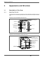
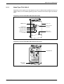
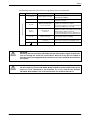
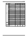
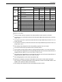
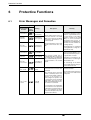
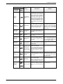
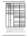
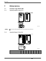
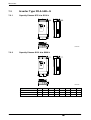
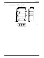
1
MITSUBISHI ELECTRIC
FR-A 500
Frequency Inverter
Installation Manual
FR-A 540 EC
FR-A 540L-G EC
Art. No: 154346
12 01 2004
Version A
MITSUBISHI ELECTRIC
INDUSTRIAL AUTOMATION
About this Manual
The texts, illustrations, diagrams, and examples contained in this manual
are only intended as aids to help explain the installation, set-up,
and starting of the frequency inverters FR-A 540 EC and FR-A 540L-G EC.
If you have any questions concerning the programming and operation of
the equipment described in this manual, please contact your relevant sales
office or department (refer to back of cover).
Current information and answers to frequently asked questions are also
available through the Internet (www.mitsubishi-automation.com).
MITSUBISHI ELECTRIC EUROPE B.V. reserves the right to make
changes both to this manual and to the specifications and design of the
hardware at any time without prior notice.
Installation Manual
FR-A 540 EC and FR-A 540L-G EC
Art. No: 141712
Version
A
2
01/04
Changes / Additions / Corrections
pdp – gb
First issue
MITSUBISHI ELECTRIC
Contents
1
Introduction
1.1
General Description . . . . . . . . . . . . . . . . . . . . . . . . . . . . . . . . . . . . . . . . . . . . . . . . . 7
2
Specifications
2.1
Model Specifications FR-A 540 . . . . . . . . . . . . . . . . . . . . . . . . . . . . . . . . . . . . . . . . 8
2.2
Model Specifications FR-A 540L-G . . . . . . . . . . . . . . . . . . . . . . . . . . . . . . . . . . . . 11
3
Appearance and Structure
3.1
Description of the Case . . . . . . . . . . . . . . . . . . . . . . . . . . . . . . . . . . . . . . . . . . . . . 14
3.1.1
Model Type FR-A 540 . . . . . . . . . . . . . . . . . . . . . . . . . . . . . . . . . . . . . . . 14
3.1.2
Model Type FR-A 540L-G . . . . . . . . . . . . . . . . . . . . . . . . . . . . . . . . . . . . 15
4
Wiring
4.1
Overview . . . . . . . . . . . . . . . . . . . . . . . . . . . . . . . . . . . . . . . . . . . . . . . . . . . . . . . . 16
4.2
Wiring of the Main Circuit . . . . . . . . . . . . . . . . . . . . . . . . . . . . . . . . . . . . . . . . . . . . 17
4.2.1
Mains, Motor and Ground Terminal Connections . . . . . . . . . . . . . . . . . . 17
4.2.2
Separate Power Supply for the Control Circuit . . . . . . . . . . . . . . . . . . . . 20
4.3
Wiring of the Control Circuit . . . . . . . . . . . . . . . . . . . . . . . . . . . . . . . . . . . . . . . . . . 22
5
Parameters
5.1
Overview and Setting Ranges . . . . . . . . . . . . . . . . . . . . . . . . . . . . . . . . . . . . . . . . 26
6
Protective Functions
6.1
Error Messages and Remedies . . . . . . . . . . . . . . . . . . . . . . . . . . . . . . . . . . . . . . . 36
7
Dimensions
7.1
Inverter Type FR-A 540 . . . . . . . . . . . . . . . . . . . . . . . . . . . . . . . . . . . . . . . . . . . . . 40
7.2
FR-A 500 EC
7.1.1
Capacity Classes 0.4 k to 3.7 k . . . . . . . . . . . . . . . . . . . . . . . . . . . . . . . . 40
7.1.2
Capacity Classes 5.5 k to 22 k . . . . . . . . . . . . . . . . . . . . . . . . . . . . . . . . 40
7.1.3
Capacity Classes 30 k to 55 k . . . . . . . . . . . . . . . . . . . . . . . . . . . . . . . . . 41
Inverter Type FR-A 540L-G . . . . . . . . . . . . . . . . . . . . . . . . . . . . . . . . . . . . . . . . . . 42
7.2.1
Capacity Classes G75 k to G110 k . . . . . . . . . . . . . . . . . . . . . . . . . . . . . 42
7.2.2
Capacity Classes G132 k to G280 k . . . . . . . . . . . . . . . . . . . . . . . . . . . . 42
7.2.3
Capacity Classes G375 k and G450 k. . . . . . . . . . . . . . . . . . . . . . . . . . . 43
3
Safety instructions
For qualified staff only
This manual is only intended for use by properly trained and qualified electrical technicians who
are fully acquainted with automation technology safety standards. All work with the hardware
described, including system design, installation, set-up, maintenance, service and testing, may
only be performed by trained electrical technicians with approved qualifications who are fully acquainted with the applicable automation technology safety standards and regulations. Any operations or modifications of the hardware and/or software of our products not specifically
described in this manual may only be performed by authorised Mitsubishi staff.
Proper use of equipment
The devices of the FR-A series are only intended for the specific applications explicitly described
in this manual. Please take care to observe all the installation and operating parameters specified in the manual. The design, manufacturing, testing and documentation of these products
have all been carried out in strict accordance with the relevant safety standards. Under normal
circumstances the products described here do not constitute a potential source of injury to persons or property provided that you precisely observe the instructions and safety information provided for proper system design, installation and operation. However, unqualified modification of
the hardware or software or failure to observe the warnings on the product and in this manual
can result in serious personal injury and/or damage to property. Only accessories specifically
approved by MITSUBISHI ELECTRIC may be used with the frequency inverters FR-A 540 EC
and FR-A 540L-G EC. Any other use or application of the products is deemed to be improper.
Relevant safety regulations
All safety and accident prevention regulations relevant to your specific application must be observed in the system design, installation, setup, maintenance, servicing and testing of these
products.
The regulations listed below are particularly important. This list does not claim to be complete;
however, you are responsible for knowing and applying the regulations applicable to you.
쎲 VDE/EN Standards
– VDE 0100
(Regulations for electrical installations with rated voltages up to 1,000V)
– VDE 0105
(Operation of electrical installations)
– VDE 0113
(Electrical systems with electronic equipment)
– EN 50178
(Configuration of electrical systems and electrical equipment)
쎲 Fire prevention regulations
쎲 Accident prevention regulations
– VBG No. 4 (electrical systems and equipment)
4
MITSUBISHI ELECTRIC
General safety information and precautions
The following safety precautions are intended as a general guideline for using the frequency
inverter together with other equipment. These precautions must always be observed in the design, installation and operation of all control systems.
P
DANGER:
쎲 Observe all safety and accident prevention regulations applicable to your specific application. Installation, wiring and opening of the assemblies, components and devices may only be performed with all power supplies disconnected.
쎲 Assemblies, components and devices must always be installed in a shockproof
housing fitted with a proper cover and protective equipment.
쎲 Devices with a permanent connection to the mains power supply must be
integrated in the building installations with an all-pole disconnection switch and
a suitable fuse.
쎲 Check power cables and lines connected to the equipment regularly for breaks
and insulation damage. If cable damage is found, immediately disconnect the
equipment and the cables from the power supply and replace the defective
cabling.
쎲 Before using the equipment for the first time check that the power supply rating
matches that of the local mains power.
쎲 Residual current protective devices pursuant to DIN VDE Standard 0641 Parts
1–3 are not adequate on their own as protection against indirect contact for
installations with frequency inverter systems. Additional and/or other protection facilities are essential for such installations.
쎲 EMERGENCY OFF facilities pursuant to VDE 0113 must remain fully operative at
all times and in all control system operating modes. The EMERGENCY OFF facility reset function must be designed so that it cannot cause an uncontrolled or
undefined restart.
쎲 You must also implement hardware and software safety precautions to prevent
the possibility of undefined control system states caused by signal line cable or
core breaks.
E
FR-A 500 EC
CAUTION:
All relevant electrical and physical specifications must be strictly observed and
maintained for all the frequency inverters in the installation.
The load used should be a three-phase induction motor only. Connection of any
other electrical equipment to the inverter output may damage the equipment.
5
Safety warnings
In this manual special warnings that are important for the proper and safe use of the products are
clearly identified as follows:
6
P
DANGER:
Personnel health and injury warnings. Failure to observe the precautions described
here can result in serious health and injury hazards.
E
CAUTION:
Equipment and property damage warnings. Failure to observe the precautions described here can result in serious damage to the equipment or other property.
MITSUBISHI ELECTRIC
Introduction
1
Introduction
This Installation Manual includes a brief summary of the main specifications of the FR-A 500 frequency inverters, which should be sufficient to enable experienced users to install and configure
the inverter. For further information on the functions and parametrization please refer to the Instruction Manual of the frequency inverter FR-A 500. This Installation Manual is intended exclusively as an installation and setup guide and a brief reference. It does not replace the main
product manual.
1.1
General Description
The inverters of the FR-A 540 EC series are available with outputs from 0.4kW to 55kW. The
higher power range from 75kW to 450kW is covered by the inverters of the FR-A 540 L-G EC series. All devices are designed for the connection to 3~ 380 to 480V (50/60Hz). The output frequency ranges from 0.2 to 400Hz.
Features of the frequency inverters
쎲 Communication ability and networking
For the integration in an automation plant a serial interface RS485 is included as standard
equipment. Through this interface up to 32 inverters can be linked up. Open communications with standardised industrial bus systems as Profibus/DP, DeviceNet, CC-Link, CAN
Open, or Modbus Plus can be realised easily via optional interface cards.
쎲 Compatibility with a lot of new applications
– PID Control
The inverter can be used to exercise process control, e.g. flow rate for pumps
– Stop function selection (terminal MRS)
This function is used to select the stopping method (deceleration to a stop or coasting).
– Brake sequence function
– Switch-over to commercial power supply
쎲 Large number of protective functions for safe operation
– Automatic restart after instantaneous power failure
The inverter can be started without stopping the motor (with the motor coasting).
– Built-in overcurrent protection
– Retry function after alarm occurence
쎲 Optimised drive characteristics
– Advanced magnetic flux vector control with auto tuning
The advanced magnetic flux vector control with auto tuning ensures a stable torque
even at ultra low speed.
FR-A 500 EC
7
Specifications
2
Specifications
2.1
Model Specifications FR-A 540
FR-A 540
Type
Rated
motor capacity
[kW] Output
150% Overload
capacity 0.75
1.1
2.2
3.0
4.0
7.5
11
15
18.5
22
30
37
45
55
75
200% Overload
capacity 0.4
0.75
1.5
2.2
4.0
5.5
7.5
11
15
18.5
22
30
37
45
55
150%
Overload
capacity Rated current
[A]
200%
Overload
capacity Rated output
capacity
[kVA]
Overload
capacity 0.4 k 0.75 k 1.5 k 2.2 k 3.7 k 5.5 k 7.5 k 11 k 15 k 18.5 k 22 k 30 k 37 k 45 k 55 k
I150
2.7
4.5
7.4
10
14
21
32
44
59
65
81
107
144
162
207
I120
2.2
3.6
5.9
8
11
17
25
35
47
52
65
85
115
130
166
Irated
1.8
3
4.9
7
9.5
14
21
29
39
43
54
71
96
108
138
I150
3
5
8
12
18
24
34
46
62
76
86
114
142
172
220
I120
2.3
3.8
6
9
14
18
26
35
47
57
65
86
107
129
165
Irated
12
17
23
31
38
43
57
71
86
110
1.5
2.5
4
6
9
150% Overload
capacity 1.3
2.3
3.7
5.1
6.9
10.6 16.0 22.1 25.7 32.8 41.1 54.1 73.1 82.3 105
200% Overload
capacity 1.1
1.9
3
4.6
6.9
9.1
65
84
3-phase, 0V up to power supply voltage 0.2–400Hz
Max. 100% / 5s
2% ED
Braking internal converter supported.
External brake unit connectable
Advanced flux vector control with online auto tuning of motor data or V/f control
Modulation control
Sine elevated PWM, Soft PWM
Carrier frequency
0.7–14.5kHz (user adjustable)
3-phase, 380–480V AC, −15 % / +10 %
Power supply voltage
Permissible AC voltage
fluctuation
Input
54
200% of rated motor capacity for 0.5s; 150% for 1min
(max. ambiente temperature 50°C); typical e.g. for cranes and stone breakers
Control method
Control specifications
32.8 43.4
Regenerative braking torque
323–528V AC bei 50 / 60Hz
50 / 60Hz ± 5%
Power supply frequency
150% Overload
capacity 1.8
3
5.4
6.1
9
14
20
26
36
41
51
66
90
100
126
200% Overload
capacity 1.5
2.5
4.5
5.5
9
12
17
20
28
34
41
52
66
80
100
Analog
0.015Hz / 50Hz (connecting terminal 2: 12 Bit / 0–10V; 11 Bit / 0–5V,
connecting terminal 1: 12 Bit /−10–+10V; 11 Bit / −5–+5V
Digital
Frequency precision
Voltage/frequency characteristic
Starting torque
29
150% of rated motor capacity for 0.5s; 120% for 1min
(max. ambiente temperature 40°C, max. carrier frequence < 2kHz);
typical e.g. for pumps, fans and extruders
Frequency range
Frequency
setting value
17.5 23.6
Rated input AC voltage
Rated input
capacity
[kVA] �
13
0.01Hz
±0.2% of max. output frequency (temperature range 25°C ± 10°C) during analog input;
±0.01% of max. output frequency during digital input
Base frequency adjustable from 0 to 400Hz;
constant torque or variable torque selectable;
optional flexible flexible 5-Point-V/f-characteristics
150% / 0.5Hz (for advanced vector control)
Please observe the notes on page 10!
8
MITSUBISHI ELECTRIC
Specifications
Specifications
Type
FR-A 540
0.4 k 0.75 k 1.5 k 2.2 k 3.7 k 5.5 k 7.5 k 11 k 15 k 18.5 k 22 k 30 k 37 k 45 k 55 k
Control specifications
Acceleration/deceleration time
Torque boost
Manual torque boost
Stall prevention
Frequency
setting
values
Control signals for operation
Linear or S-form course,user selectable
Braking time and braking moment adjustable,
operation frequency: 0–120Hz, operation time: 0–10s,
Voltage: 0–30%
DC braking
Respones treshold 0–200%, user adjustable, also via analog input
Motor protection
Input
signals
Analog input
From control panel or optional circut board
Starting signal
Speed selection
Up to 15 speed settings can be selected (each speed can be preset from 0 to 400Hz).
The current speed can be changed via the control panel during operation.
2nd/3rd acceleration/deceleration
time
0 to 3600 seconds
(Acceleration and deceleration time can be set individually.)
Output stop
Jog operation via control panel or special JOG-terminal
Frequency setting via current input signal 0/4 to 20mA DC
Instant cutoff of inverter output (frequency and voltage)
Error reset
The error indication (alarm signal) is reset with the reset of the protective function.
Operation
state
5 five output types can be selected:
inverter running, frequency reached, instantaneous power failure (undervoltage), frequency
detection, 2nd frequency detection, 3rd frequency detection, in PU operation, overload warning, regenerative brake pre-alarm, electronic thermal relay pre-alarm, zero current detection,
output current detection, PID lower limit, PID upper limit, PID forward run, PID reverse run,
commercial power supply-inverter switchover MC1-2-3, operation ready, brake release request, fan trouble, overheat fin pre-alarm (open-collector-output)
Alarm
functions
Relay output ... contactor(230V AC / 0.3A, 30V DC / 0.3A)
Open collector output ... error message through alarm code (4 bits)
Analog
signal
or
pulse train
One of the following output types can be selected:
output frequency, motor current (constant or peak value), output voltage,
frequency setting value, operation speed, motor torque,
converter output voltage (constant or peak value), regenerative brake duty, electronic thermal
relay load rate, input power, output power, load meter, motor excitation current,
pulse train output (1440Hz/full scale), or analog output (0–10V DC).
Operating
state
Output frequency, motor current (constant or peak value), output voltage, frequency setting
value, operation speed, motor torque, overload, converter output voltage (constant or peak
value), electronic thermal relay load rate, input power, output power, load meter, motor excitation current, cumulative power ON time, current operation time, cumulative power,
regenerative brake duty, and motor load rate.
Alarm display
Operating state
Additional
displays on
control panel
FR-PU04
0–5V DC, 0–10V DC, 0–±10V DC, 0/4–20mA
Individual selection of forward / reverse run
Start signal self retaining input.
Current input
selection
Displayed on
control panel
(FR-PU04/
FR-DU04)
Electronic motor protection relay (rated current user adjustable)
Digital input
JOG operation
Output
signals
Display
0; 0.1 to 3600s individual settings
Acceleration/deceleration
characteristics
Alarm display
Interactive
operating guide
Error details are displayed after a protective function is activated.
Up to 8 error codes can be stored.
Signal state of input and output terminals.
Output voltage, output current, output frequency, cumulative power ON time
before activation of protective function
Interactive guide for operation and troubleshooting via help function
Please observe the notes on page 10!
FR-A 500 EC
9
Specifications
FR-A 540
Protection
Type
0.4 k 0.75 k 1.5 k 2.2 k 3.7 k 5.5 k 7.5 k 11 k 15 k 18.5 k 22 k 30 k 37 k 45 k 55 k
Overcurrent cutoff (during acceleration, deceleration, constant speed),
regenerative overvoltage cutoff, undervoltage, instantaneous power failure, overload cutoff
(electronic thermal relay), brake transistor error , ground fault overcurrent, output short circuit, overheating of main circuit, stall prevention, overload warning, brake transistor overheating, fin overheating, fan error, option error, parameter error, PU connection error, output of
group error message via relay contact (220V AC / 0.3A; 30V DC / 0.3A).
Functions
IP 20 Protective structure
Environment
Ambient temperature in operation
Storage temperature −20°C to +65°C
Ambient humidity
Max. 90% RH (non-condensing)
For indoor use only, avoid environments containing corrosive gases, no oil mist,
install in a dust-free location
Ambience condition
Max. 1000m above n.N.
After that derate by 3% for every extra 500m up to 2500m (91%)
Altitude
Vibration resistance
Cooling
Max. 0.6g
Self-cooling
Weight (kg)
3.5
NOTES
3.5
3.5
Fan-cooling
3.5
3.5
6.0
6.0
13.0 13.0 13.0 13.0 24.0 35.0 35.0 36.0
Special notes referring to the table:
10
IP 00
−10°C to +50°C (non freezing)
(For selection of the overload capacity of 150% the max. temperature is 40°C)
At 150% rating a maximum ambient temperature of 40°C is allowed and the PWM carrier
frequency must be less than 2kHz.
The overload capacity indicated in % is the ratio of the overload current to the inverter’s
rated current. For repeated duty, allow time for the inverter and motor to return to or below
the temperatures under 100% load.
The maximum output voltage cannot exceed the power supply voltage. The maximum output voltage may be set as desired below the power supply voltage.
The power supply capacity changes with the values of the power supply side inverter impedances (including those of the input reactor and cables).
The brake transistor alarm is only provided for inverters with a capacitiy between 0.4 k to
7.5 k that are equipped with a built-in brake circuit.
Temperature applicable for a short period in transit, etc.
It is not possible to connect single-phase motors in general.
The protective structure changes to IP 00 when a inboard option is fitted after removal of
the option wiring port cover.
MITSUBISHI ELECTRIC
Specifications
Model Specifications FR-A 540L-G
2.2
FR-A 540L
Type
Rated
motor capacity
[kW] G75 k
G90 k
G110 k
G132 k
G160 k
G220 k
G280 k
G375 k
G450 k
120% Overload
capacity —
132
160
220
250
315
400
530
530
150% Overload
capacity 90
110
132
185
220
280
375
450
530
200% Overload
capacity 75
90
110
132
160
220
280
375
450
I120
—
312
362
518
572
732
900
1212
1212
I110
—
286
332
475
525
671
825
1111
1111
Irated
—
260
302
432
477
610
750
1010
1010
I150
270
324
390
542
648
821
1083
1299
1515
I120
216
259
312
433
518
656
866
1039
1212
Irated
180
216
260
361
432
547
722
866
1010
I200
288
360
432
520
650
864
1094
1444
1732
I150
216
270
324
390
488
648
821
1083
1299
144
180
216
260
325
432
547
722
866
—
198
230
329
364
465
572
770
770
150% Overload
capacity 137
165
198
275
329
417
550
660
770
200% Overload
capacity 110
137
165
198
248
329
417
550
660
120%
Overload
capacity 150%
Overload
capacity Rated
current [A] Output
200%
Overload
capacity Irated
120% Overload
capacity Rated output
capacity
[kVA]
Overload
capacity 120% of rated motor capacity 0.5s; 110% for 1min
(max. ambiente temperature 40°C); typical e.g. for pumps and fans
150% of rated motor capacity for 0.5s; 120% für 1min
(max. ambiente temperature 50°C); typical e.g. for pumps, fans and extruders
200% of rated motor capacity for 0.5s; 150% für 1min
(max. ambiente temperature 50°C); typical e.g. for cranes and stone breakers
Voltage
3-phase 0V up to power supply voltage Frequency range
0.2–400Hz
Control method
Advanced flux vector control with online auto tuning of motor data or V/f control
Modulation control
Sine elevated PWM, Soft PWM
Carrier frequency
0.7kHz / 1kHz / 2.5kHz (user adjustable) to 5kHz
3-phase, 380–480V AC, −15% / +10%
Power supply voltage
323–528V AC at 50 / 60Hz
Power supply frequency
50 / 60Hz ± 5%
Input
Permissible AC voltage
fluctuation
Controlspecifikations
Rated input
capacity
[kVA] 120% Overload
capacity —
198
230
329
364
465
572
770
770
150% Overload
capacity 137
165
198
275
329
417
550
660
770
200% Overload
capacity 110
137
165
198
248
329
417
550
660
Analog
Frequency
setting value
0.015Hz / 50Hz (connecting terminal 2: 12 Bit / 0–10V; 11 Bit / 0–5V,
connecting terminal 1: 12 Bit /−10–+10V; 11 Bit / −5–+5V
Digital
Frequency precision
Voltage/frequency characteristic
Starting torque
0.01Hz
±0.2% of max. output frequency (temperature range 25°C ± 10°C) during analog input;
±0.01% of max. output frequency during digital input
Base frequency adjustable from 0 to 400Hz;
constant torque or variable torque selectable;
optional flexible 5-Point-V/f-characteristics
150% / 0.5Hz (for advanced vector contro)
Please observe the notes on page 13!
FR-A 500 EC
11
Specifications
Type
FR-A 540L
G75 k
G90 k
G110 k
Control specifications
Acceleration/deceleration time
G132 k
G160 k
G220 k
G280 k
G375 k
G450 k
0; 0.1 to 3600s individual settings
Acceleration/deceleration
characteristics
Linear or S-form course, user selectable
Braking time and braking moment adjustable,
Operation frequency: 0–120Hz, operation time: 0–10s,
Voltage: 0–30%
DC braking
Torque boost
Manual torque boost
Response treshold
0–150%
Response treshold 0–200%
Stall prevention
User adjustable
Motor protection
Frequency
setting
values
Analog input
0–5V DC, 0–10V DC, 0–±10V DC, 0/4–20mA
Digital input
From control panel or optional circut board
Starting signal
Individual selection of forward / reverse run
Start signal self retaining input.
Speed selection
Input
signals
Controlsignals for operation
Display
2nd/3rd acceleration/deceleration
time
JOG operation
Current input
selection
Output
signals
Displayed on
control panel
(FR-PU04/
FR-DU04)
Up to 15 speed settings can be selected (each speed can be preset from 0 to 400Hz).
The current speed can be changed via the control panel during operation.
0 to 3600 seconds
(Acceleration and decelleration time can be set individually.)
Jog operation via control panel or special JOG terminal
—
Frequency setting via current input signal 0/4 to 20mA DC
Output stop
Instant cutoff of inverter output (frequency and voltage)
Error reset
The error indication (alarm signal )is reset with the reset of the protective function
Operation
state
5 five output types can be selected:
Inverter running, frequency reached, instantaneous power failure (undervoltage), frequency
detection, 2nd frequency detection, 3rd frequency detection, in PU operation, overload warning, regenerative brake pre-alarm, electronic thermal relay pre-alarm, zero current detection,
output current detection, PID lower limit, PID upper limit, PID forward run, PID reverse run,
commercial power supply-inverter switchover MC1-2-3, operation ready, brake release request, fan trouble, overheat fin pre-alarm (open-collector-output)
Alarm
functions
Relay output ... contactor(230V AC / 0.3A, 30V DC / 0.3A)
Open collector output ... error message through alarm code (4 bits)
Analog
signal
or
pulse train
One of the following output types can be selected:
output frequency, motor current (constant or peak value), output voltage,
frequency setting value, operation speed, motor torque,
converter output voltage (constant or peak value) regenerative brake duty, electronic thermal
relay load rate, input power, output power, load meter and motor excitation current,
pulse train output (1440Hz/full scale), or analog output (0–10V DC)
Operating
state
Output frequency, motor current (constant or peak value), output voltage, frequency setting
value, operation speed, motor torque, overload, converter output voltage (constant or peak
value), electronic thermal relay load rate, input power, output power, load meter, motor excitation current, cumulative power ON time, current operation time, cumulative power, regenerative brake duty, and motor load rate.
Alarm display
Operating state
Additional
displays on
control panel
FR-PU04
Electronic motor protection relay (rated current user adjustable)
Alarm display
Interactive
operating guide
Error details are displayed after a protective function is activated.
Up to 8 error codes can be stored.
Signal state of input and output terminals.
Output voltage, output current, output frequency, cumulative power ON time
before activation of protective function
Interactive guide for operation and troubleshooting via help function
Please observe the notes on page 13!
12
MITSUBISHI ELECTRIC
Specifications
FR-A 540L
Protection
Type
G75 k
G90 k
G110 k
G132 k
Protective structure
Environment
G220 k
G280 k
G375 k
G450 k
Overcurrent cutoff (during acceleration, deceleration, constant speed),
regenerative overvoltage cutoff, undervoltage, instantaneous power failure,
overload cutoff (electronic thermal relay), ground fault overcurrent, output short circuit,
overheating of main circuit, stall prevention, overload warning, fin overheating,
fan error, option error, parameter error, PU connection error, No. of retries over,
output open phase, CPU error, 24V DC power supply output short circuit,
operation panel power supply short circuit, main circuit error,
output of group error message via relay contact (220V AC / 0.3 A; 30V DC / 0.3A).
Functions
IP 00
200% and 150%
overload capacity:
−10°C to +50°C
120% overload
capacity:
−10°C to +40°C
(non freezing)
−10°C to +50°C (non freezing)
Ambient temperature
Storage temperature −20°C to +65°C
Ambient humidity
Max. 90% RH (non-condensing)
For indoor use only, avoid environments containing corrosive gases, no oil mist,
install in a dust-free location
Ambience condition
Altitude
Max. 1000m above n.N.
Vibration resistance
Max. 0.6g
Cooling
Fan-cooling
Weight (kg)
57
NOTES
66
66
120
120
220
235
490
500
Special notes referring to the table:
FR-A 500 EC
G160 k
The applicable motor capacity refers to a motor voltage of 400V, a maximum ambient temperature of 40°C and a PWM carrier frequency of less than 1kHz.
The rating 120% is available with serial marking “type 2” only (shipping from 02.2003).
The overload capacity indicated in % is the ratio of the overload current to the inverter’s
rated current. For repeated duty, allow time for the inverter and motor to return to or below
the temperatures under 100% load.
The maximum output voltage cannot exceed the power supply voltage. The maximum output voltage may be set as desired below the power supply voltage.
The power supply capacity changes with the values of the power supply side inverter impedances (including those of the input reactor and cables).
Temperature applicable for a short period in transit, etc.
It not possible to connect single-phase motors in general.
13
Appearance and Structure
3
Appearance and Structure
3.1
Description of the Case
3.1.1
Model Type FR-A 540
Depending on the capacity class the frequency inverter is delivered in four different structural
shapes of the case. The following drawings show a structured view of the single case components.
Frequency inverter FR-A 540 EC with front cover
Built-in brake resistor
(fitted to the back)
POWER lamp
Hz
A
V
POWER
ALARM
MON
ALARM lamp
MODE
Removable control
panel FR-DU04
SET
PU
EXT
REV
FWD
REV
FWD
STOP
RESET
Front cover
Accessory cover
Wiring port cover
for option
DATA PORT
MITSUBISHI
Model type
Capacity plate
Frequency inverter FR-A 540 EC without front cover
PU connector
(Provided with modular
jack type relay connector/
for use of a RS485-cable)
R1
CHARGE
S1
Modular jack type relay
connector compartement
Inboard option
mounting position
CHARGE lamp
Control circuit
terminal block
Main circuit
terminal block
R
N
S
P1
T
P
U
PR
V
W
Wiring cover
14
MITSUBISHI ELECTRIC
Appearance and Structure
3.1.2
Model Type FR-A 540L-G
Depending on the capacity class the frequency inverter is delivered in three different structural
shapes of the case. The following drawings show a structured view of the single case components.
Frequency inverter FR-A 540L-G EC with front cover
Front cover
POWER lamp
Hz
A
V
POWER
ALARM
MON
PU
EXT
REV
FWD
88
CHARGE
ALARM
ALARM lamp
Removable control
panel FR-DU04
MODE
SET
REV
FWD
STOP
RESET
Display window
error E.15
DATA PORT
MITSUBISHI
A 500L
Accessory cover
Main circuit
terminal cover
Wiring port cover
for option
Frequency inverter FR-A 540L-G EC without front cover
CHARGE lamp
88
CHARGE
ALARM
Main circuit
terminals
FR-A 500 EC
15
Wirings
4
Wiring
4.1
Overview
E
CAUTION:
The terminals PC-SD of the 24V DC power supply must not be shorted. Otherwise the
inverter will be damaged.
P1
P/+
PX
PR
N/–
Intermediate circuit
Mains supply
L11
L21
Motor
U
V
W
L1
L2
L3
Voltage
supply
Input signal
circuits
CHARGE
PC
STF
STR
STOP
RH
RM
RL
RT
JOG
MRS
AU
CS
SD
RES
Reset
Protective
circuits
ALARM
CPU
Options
16
AM
5
Analog
output
SE
RUN
SU
OL
IPF
FU
PU/DU
4–20 mA
±0–5 V
(10 V)
Error
output
Hz
FM
SD
LSI
Control panel
10E
10
2
5
4
1
A
B
C
Operating
state
and
error
output
LCD/LED display PU/DU
The JOG terminal is connected internally for the frequency inverters FR-A 540L-G375 k
and G450 k and cannot be used by the customer.
The designations and wiring of the intermediate circuit connections varies depending on
the output of the frequency inverter model and if a DC choke coil is used (see also section
4.2.1). The PX and PR connections are only available in models FR-A 540-0.4 k through
7.5 k.
MITSUBISHI ELECTRIC
Wiring
4.2
Wiring of the Main Circuit
P
DANGER:
The frequency inverter must always be powered off completely before performing
any wiring work. To ensure that no residual charge is present check that both the
POWER and CHARGE LEDs are off before starting work!
E
CAUTION:
Power must not be applied to the output terminals (U, V, W) of the inverter. Otherwise
the inverter will be damaged.
The inverter must be grounded using the dedicated ground terminal.
4.2.1
Mains, Motor and Ground Terminal Connections
The terminal blocks for connection of the frequency inverter can be accessed by removing the
front cover (FR-A 540) or the terminal block cover (FR-A 540L-G). The mains power supply is
connected to terminals L1, L2 and L3. Required power supply: 380–480V, −15% / +10%;
50–60Hz ± 5%.
Connect the motor cables to terminals U, V and W. The illustration below shows the correct assignments for the power connections. Please see the main frequency inverter manual for details
on the required cable dimensions for your model.
NOTE
The inverter must be grounded using the dedicated ground terminal.
Ground terminal for
inverters with a
capacity of 0.4–3.7 k
Ground terminal for
FR-A 540L-G65 k–280 k
FR-A 500 EC
17
Wiring
NOTE
It is recommended to use a shielded motor cable in order to reduce cable radiation.
Q1
Frequenzumrichter
L1
I
L1
L2
I
L2
V
L3
I
L3
W
U
L11
L21
P1
(P0)
P/+
PR
PE
NOTE
18
N/−
The maximum wiring length of the motor cable ist 300m for the 0.4 k capacity inverter and
500m from 0.75 k upwards.
MITSUBISHI ELECTRIC
Wiring
Main circuit connector
The following table shows the terminal assignment of main circuit terminals.
Terminal
Terminal name
L1, L2, L3
Mains supply connection
P/+, N/−
External brake unit connection
An external brake unit can be connected to the
terminals P/+ and N/−.
P/+, PR
Optional external brake
resistor connection
An optional external brake resistor can be connected to the terminals P/+ and PR.
Disconnect the jumper from terminals PR and PX
before (FR-A 540-0.4 k to 7.5 k only).
P1, P/+
(P0, P1)
DC choke coil
connection
An optional choke coil can be connected to the
terminals P1 and P/+ (up to 280 k) or between P0
and P1 (375 k to 450 k) respectively.
For all FR-A 540L-G inverters the supplied choke
coil has to be installed to the mentioned terminals
U, V, W
Motor connection
Voltage output of the inverter (3-phase, 0V up to
power supply voltage, 0.2–400Hz)
L11, L21
Control circuit mains supply
connection
PE
E
E
FR-A 500 EC
Description
Mains power supply of the inverter
(380–480V AC, 50/60Hz)
Mains power supply input for a separate supply
of the control circuit (refer to paragraph 4.2.2).
Protective earth connection of inverter
CAUTION:
Switching the unit off and on repeatedly with the mains power supply at short intervals can damage the switch-on current limiter. Because of this the unit should always be started and stopped with the control unit or via the STF/STR and STOP control signals.
CAUTION:
For the frequency inverters FR-A540L-G75 k to 280 k the enclosed DC choke coil always has to be connected to the terminals P1 an P(+) and for the inverters
FR-A540L-G375 k/450 k it has to be connected to the terminals P0 and P1.
19
Wiring
4.2.2
Separate Power Supply for the Control Circuit
In an alarm condition the frequency inverter’s integrated alarm relay only remains active as long
as there is a mains power supply on terminals L1, L2 and L3. If you want the alarm signal to remain active after the frequency inverter has been switched off a separate power supply for the
control circuit is required, which should be connected as shown in the circuit diagram below. Remove the shorting jumpers from the terminal block and connect the 380–480V AC, 50/60Hz
mains power supply to terminals L11 and L21. The control circuit power consumption on
L11/L21 is 120VA. We recommend using a fuse with a rating of at least 5A to protect the circuit.
Q1
L1
Main power
supply L2
L3
Control circuit
mains supply
E
20
FR-A 500
I
L1
I
L2
I
L3
L11
L21
CAUTION:
When using a separate power supply, the jumpers must be removed and the terminals L11 and L21 of the terminal block must be connected. Otherwise the inverter
may be damaged.
MITSUBISHI ELECTRIC
Wiring
Remove the jumpers as follows:
Loosen the upper screws and then the lower screws .
Pull out and remove the jumper .
Connect the seperate power supply cabels for control circuits for the inverters
FR-A 540-0.4 k to 3.7 k to the lower , and for the inverters FR-A 540-5.5 k to 55 k and
FR-A 540L-G to the upper terminals (L11 and L21).
L1
L2
L3
Terminal block
L11
FR-A 500 EC
L21
Terminal block
L21
FR-A 540-0.4 k to 3.7 k
E
L11
FR-A 540-5.5 k to 55 k and FR-A 540L-G
CAUTION:
The power supply cables must not be connected to the lower terminals for the 5.5 k to
55 k capacity frequency inverters and the inverter FR-A 540L-G. Otherwise the inverter may be damaged.
21
Wiring
4.3
Wiring of the Control Circuit
The following picture shows the arrangement of the terminal for the control circuit of the inverter.
A
B
Control connection
SE
C
RUN
SU
AM
IPF
10E
OL
10
FU
2
5
STOP MRS
4
RES
1
PC
RL
STF
RM
STR
RH
JOG
RT
CS
AU
FM
SD
Terminal
Terminal name
STF
Forward rotation start
The motor rotates forward, if a signal is applied to
terminal STF.
STR
Reverse rotation start
The motor rotates reverse, if a signal is applied to
terminal STR.
STOP
Start self-retaining selection
The start signals are self-retaining, if a signal is
applied to terminal STOP.
RH, RM, RL
Multi-speed selection
Preset of 15 different output frequencies
JOG
JOG mode selection
The JOG mode is selected, if a signal is applied to
terminal JOG (factory setting). The start signals
STF and STR determine the rotation direction.
The inverters FR-A 540L-G375 k and G450 k are
not equipped with a JOG terminal.
RT
Second parameter settings
A second set of parameter settings is selected, if a
signal is applied to terminal RT.
MRS
Output stop
The inverter lock stops the output frequency without regard to the delay time.
RES
RESET input
An activated protective circuit is reset, if a signal is
applied to the terminal RES (t > 0.1s).
AU
Current input selection
Only if the AU signal is ON, the inverter can be operated with the 0/4–20mA frequency setting
signal.
Automatic restart after power
failure selection
The inverter restarts automatically after a power
failure, if a signal is applied to the terminal CS.
Note that this operation requires restart parameters to be set. When the inverter is shipped from
the factory, it is set to disallow restart.
CS
22
SD
Description
MITSUBISHI ELECTRIC
Wiring
Terminal
PC
Common sink for contact
input/reference potential
24V DC output
and control input common if
source logic type is activated
24V DC/0.1A output
With negative logic and control via open collector
transistors (e.g. a PLC) the positive pole of an external power source must be connected to the PC
terminal. With positive logic the PC terminal is
used as a common reference for the control inputs. This means that when positive logic is selected (default setting of the EC units) the corresponding control function is activated by
connecting its terminal to the PC terminal.
10 E
(output voltage
10V DC)
Voltage output for
potentiometer
Setting value specification
10
(output voltage
5V DC)
FR-A 500 EC
2
5
Description
A determined control function is activated, if the
corresponding terminal is connected to the terminal SD (sink logic). The SD terminal is isolated
from the digital circuits via optocouplers.
Reference potential for the pulse output FM. The
terminal is isolated from the reference potential of
the control circuit.
Common reference potential for 24V DC/0.1A
output (PC terminal).
Common
SD
Terminal name
Input for frequency setting
value signal
Output voltage 10V DC
Max. output current 10mA
Recommended potentiometer: 1kΩ, 2W linear,
multiturn potentiometer
Output voltage 5V DC
Max. output current 10 mA
Recommended potentiometer: 1kΩ, 2W linear
multiturn potentiometer
The voltage setting value 0–5 (10) V is applied to
this terminal. The voltage range is preset to 0–5V.
(Parameter 73). The input resistance is 10kΩ. .
Terminal 5 is the reference point for all analog setting values and for the analog output signal AM.
Reference point for frequency The terminal is not isolated from the reference posetting value signal
tential of the control circuit and must not be
earthed.
1
Auxiliary input for frequency
setting value signal
0–±5 (10)V DC
4
Input for current
setting value signal
0/4–20mA DC
An additional voltage setting value signal of 0–±5
(10)V DC can be applied to terminal 1.
The voltage range is preset to 0–±10V DC. The input resistance is 10kΩ.
The current setting value signal (0/4–20mA DC) is
applied to this terminal. The input resistance is
250Ω, the max current is 30mA.
23
Wiring
Terminal
Terminal name
Description
The alarm is output via relay contacts. The block
diagram shows the normal operation and voltage
free status. If the protective function is activated,
the relay picks up.
B
A, B, C
A
Potential free
alarm output
C
Signaloutputs
The maximum contact load is 230V / 0.3A AC or
30V / 0.3A DC.
RUN
Signal output for
motor operation
(open collector)
The output is switched low, if the inverter output
frequency is equal to the starting frequency.
The output is switched high, if no frequency is output or the DC brake is in operation.
SU
Signal output for frequency
setting value / current value
comparison
(open collector)
The SU output supports a monitoring of frequency
setting value and frequency current value. The
output is switched low, once the frequency current
value (output frequency of the inverter) approaches the frequency setting value (determined
by the setting value signal) within a preset range
of tolerance (parameter 41).
IPF
Signal output for
instantaneous power failure
(open collector)
The output is switched low for a temporary power
failure within a range of 15ms ≤ tIPF ≤ 100ms or for
undervoltage.
OL
Signal output for
overload alarm
(open collector)
The OL is switched low, if the output current of the
inverter exceeds the current limit preset in parameter 22 and the stall prevention is activated. If the
output current of the inverter falls below the current limit preset in parameter 22, the signal at the
OL output is switched high.
FU
Signal output for
monitoring output frequency
(open collector)
The output is switched low once the output frequency exceeds a value preset in parameter 42
(or 43). Otherwise the FU output is switched high.
SE
Reference potential for
signal outputs
Reference potential for the signals RUN, SU, OL,
IPF, and FU. This terminal is isolated from the reference potential of the control circuit SD.
Pulse output
One of 16 monitoring functions can be selected,
e.g. external frequency output (parameter 54; parameter 158). FM and AM output can be used simultaneously.
The functions are determined by parameters.
Either a moving coil gauge (measuring range:
1mA) or a pulse counter with an initial setting of
1440 pulses/s at 50Hz output frequency.
AM
Analog output
One of 16 monitoring functions can be selected,
e.g. external frequency output (parameter 54; parameter 158). FM and AM output can be used simultaneously.
The functions are determined by parameters.
A DC voltmeter can be connected. The max. output voltage is 10V, the max. current is 1mA.
—
Connection of
control panel (RS485)
Communications via RS485
I/O standard: RS485, Multi-Drop operation, max.
19200 Baud, Overall length max. 500m
FM
24
MITSUBISHI ELECTRIC
Wiring
E
NOTES
CAUTION:
Terminals 10/10E and 5 must not be connected to each other. Otherwise the internal
voltage output for the connection of the potentiometer will be damaged.
The control signal level can be adjusted with the jumper on the underside of the removable
control terminal block (unscrew the two retaining screws to remove). At the factory the
jumper on the EC units is set to the “Source” position (positive logic, 24V DC corresponds to
logical 1). If you want to use negative logic (0V corresponds to logical 1) you must move the
jumper to the “Sink” position. Use tweezers or thin-nosed pliers to move the jumper.
The control terminals RL/RM/RH/RT/AU/JOG (only on models up to 280 k)/CS (input terminals) and RUN/SU/IPF/OL/FU/A, B, C (output terminals) can be assigned to other functions
or signals with the help of the control unit (FR-DU04 or FR-PU04), the PC software or a field
bus system. Please see the frequency inverter manual for details on the procedure for this.
Please note the following important points for proper frequency inverter control performance:
쎲 The following conditions must be fulfilled for the frequency inverter to output a rotating field
correctly:
– The inverter lock must be deactivated (see below).
– You must input both a direction of rotation signal and a frequency setpoint value to the
inverter.
쎲 If the frequency inverter does not work properly even though the wiring of the control terminals block appears to be correct please check the following points:
– Is the frequency inverter reporting an error condition (red alarm LED)?
– Is the correct operating mode selected (EXT mode for control via the terminal block, PU
mode for control via the control unit)?
– Is the inverter lock (terminal MRS) deactivated and is the inverter receiving a rotation
start signal (terminal STF or STR)?
– Is the inverter receiving a valid frequency setpoint value > the start frequency (voltage
signal on terminal 2, current signal on terminal 4, preset frequency digital inputs)?
– Are the control terminals you are using programmed correctly?
FR-A 500 EC
25
Parameters
5
Parameters
5.1
Overview and Setting Ranges
Function
Basic
functions
26
FR-A 540
Default setting
FR-A 540L-G
FR-A 540
FR-A 540L-G
6% / 4% /
3% / 2% 1%
120Hz
60Hz
0
Torque boost (manual) 1
Maximum frequency
2
Minimum frequency
0–120Hz
0Hz
3
Base frequency
0–400Hz
50Hz
4
Multi-speed setting (high speed) 0–400Hz
60Hz
0–400Hz
30Hz
5
Standard
operation
functions
Setting range
ParaMeaning
meter
0–30%
0–120Hz
Multi-speed setting (middle speed)
6
Multi-speed setting (low speed)
7
Acceleration time
0–60Hz
0–400Hz
0–360s / 0–3600s
8
Deceleration time
9
Electronic thermal overload relay
10
DC injection brake operation
frequency
11
DC injection brake operation time
0–360s / 0–3600s
0–500A
0–3600A
10Hz
5s / 15s 5s / 15s
15s
15s
Rated current
0–120Hz / 9999
3Hz
0–10s / 8888
0.5s
12
DC injection brake voltage
0–30%
13
Starting frequency
0–60Hz
0.5Hz
14
Load pattern selection 0–5
0
15
JOG frequency
0–400Hz
5Hz
16
JOG acceleration / deceleration time
0–360s / 0–3600s
0.5s
17
MRS input selection
18
High-speed max. frequency
4% / 2%
0/2
120–400Hz
19
Base frequency voltage
20
Acceleration / deceleration reference
frequency
21
Acceleration / deceleration time
increments
22
Stall prevention operation level
23
Stall prevention operation at double
speed
1%
0
0–400Hz
120Hz
60Hz
0–1000V / 8888 / 9999
8888
1–400Hz
50Hz
0/1
0
0–200% / 9999
0–200 % / 9999
150%
150%
(M = const)
120%
(M ~ n²) 9999
MITSUBISHI ELECTRIC
Parameters
Function
Standard
operation
functions
Output
terminal
functions
Second
functions
Display
functions
FR-A 500 EC
Setting range
ParaMeaning
meter
FR-A 540
FR-A 540L-G
Default setting
FR-A 540
FR-A 540L-G
24
Multi-speed setting (speed 4) 0–400Hz / 9999
9999
25
Multi-speed setting (speed 5) 0–400Hz / 9999
9999
26
Multi-speed setting (speed 6)
0–400Hz / 9999
9999
27
Multi-speed setting (speed 7) 0–400Hz / 9999
9999
28
Multi-speed input compensation
0/1
0
29
Acceleration / deceleration pattern
0/1/2/3
0
30
Regenerative function selection
0/1/2
0
31
Frequency jump 1A
0–400Hz / 9999
9999
32
Frequency jump 1B
0–400Hz / 9999
9999
33
Frequency jump 2A
0–400Hz / 9999
9999
34
Frequency jump 2B
0–400Hz / 9999
9999
35
Frequency jump 3A
0–400Hz / 9999
9999
36
Frequency jump 3B
0–400Hz / 9999
9999
37
Speed display
0 / 1–9998
0
41
Up-to-frequency sensitivity
0–100%
10%
42
Output frequency detection
0–400Hz
6Hz
43
Output frequency detection for reverse
rotation
0–400Hz / 9999
9999
44
Second acceleration/deceleration time
0–360s / 0–3600s
5s
45
Second deceleration time
0–360s / 0–3600s / 9999
9999
46
Second torque boost 0–30% / 9999
9999
0–400Hz / 9999
9999
47
Second V/F (base frequency)
48
Second stall prevention operation
current
0–200%
49
Second stall prevention operation
frequency
0–400Hz / 9999
0Hz
50
Second output frequency detection
0–400Hz
30Hz
52
DU/PU main display data selection 0 / 5–14 / 17 / 18 / 20 /
23 / 24 / 25 / 100
0
53
PU level display data selection 0–3 / 5–14 / 17 / 18
1
54
1–3 / 5–14 / 17 / 18 / 21
1
FM terminal function selection
55
Frequency monitoring reference
56
Current monitoring reference Automatic
restart
functions
57
Restart coasting time
58
Restart cushion time
Additional
function
59
Remote setting function selection
0–400Hz
150%
(M = const)
120%
(M ~ n²) 150%
50Hz
0–500A
0–3600A
Rated current
0–5s / 9999
0–30s / 9999
9999
0–60s
1s
0/1/2
0
27
Parameters
Function
Operation
selection
functions
Motor
constants
28
Setting range
ParaMeaning
meter
FR-A 540
Default setting
FR-A 540L-G
FR-A 540
FR-A 540L-G
60
Intelligent mode selection
61
Reference I for intelligent mode
62
Reference I for intelligent mode
(acceleration)
0–200% / 9999
9999
63
Reference I for intelligent mode
(deceleration)
0–200% / 9999
9999
64
Starting frequency for elevator mode
0–10Hz / 9999
9999
65
Retry selection
0–5
0
66
Stall prevention operation reduction
starting frequency
0–400Hz
50Hz
67
Number of retries at alarm occurrence
0–10 / 101–110
0
68
Retry waiting time
0–10s
1s
69
Retry count display erasure
0
0
70
Special regenerative brake duty
71
Applied motor
72
PWM frequency selection 73
0–5V / 0–10V selection
74
Filter time constant
0–8
0–500A /
9999
0
0–3600A /
9999
0–15% /
0–30% /
0% 9999
0–100%
0%
0–8 / 13–18
0–15
0–5 / 17
0
2
1
0–5 / 10–15
1
0–8
1
0–3 /
14–17 /
100–117
75
Reset selection / disconnected PU
detection / PU stop selection 76
Alarm code output selection
0/1/2/3
0
77
Parameter write disable selection 0/1/2
0
78
Reverse rotation prevention selection
0/1/2
0
79
Operation mode selection
0–8
0
0–3 /
14–17
0.4–55kW/
9999
0–3600kW/
9999
14
80
Motor capacity
81
Number of motor poles
82
Motor excitation current
0– / 9999
9999
83
Rated motor voltage
0–1000V
400V
84
Rated motor frequency
50–120Hz
50Hz
89
Speed control gain
0–200%
100%
90
Motor constant R1 0– / 9999
9999
91
Motor constant R2
0– / 9999
9999
92
Motor constant L1
0– / 9999
9999
93
Motor constant L2 0– / 9999
9999
0– / 9999
9999
2 / 4 / 6 / 12 / 14 / 16 /
9999
9999
9999
94
Motor constant X
95
Online auto tuning selection
0/1
0
96
Auto tuning setting / status
0 / 1 / 101
0
MITSUBISHI ELECTRIC
Parameters
Function
5-point
flexible V/f
characteristics
Third
functions
Communications
functions
PID
control
Commercial
power
supplyinverter
switchover
FR-A 500 EC
Setting range
ParaMeaning
meter
FR-A 540
100
V/F1 (first frequency) 101
V/F1 (first frequency voltage) 102
V/F2 (second frequency)
103
V/F2 (second frequency voltage) 104
V/F3 (third frequency)
105
V/F3 (third frequency voltage)
106
V/F4 (fourth frequency) 107
V/F4 (fourth frequency voltage) FR-A 540L-G
Default setting
FR-A 540
FR-A 540L-G
0–400Hz / 9999
9999
0–1000V
0
0–400Hz / 9999
9999
0–1000V
0
0–400Hz / 9999
9999
0–1000V
0
0–400 Hz / 9999
9999
0–1000V
0
0–400Hz / 9999
9999
0–1000V
0
108
V/F5 (fifth frequency)
109
V/F5 (fifth frequency voltage) 110
Third acceleration / deceleration time
0–360s / 0–3600s /
9999
9999
111
Third deceleration time
0–360s / 0–3600s /
9999
9999
112
Third torque boost 0–30% / 9999
9999
113
Third V/F (base frequency) 0–400Hz / 9999
9999
114
Third stall prevention operation
current
0–200%
115
Third stall prevention operation
frequency
0–400Hz
0
116
Third output frequency detection
0–400Hz / 9999
9999
150%
(M = const)
120%
(M ~ n²) 150 %
117
Station number
118
Communication speed
119
Stop bit length / data length
120
Parity check presence / absence
0/1/2
2
121
Number of communication retries
0–10 / 9999
1
122
Communication check time interval
0–999.8s / 9999
9999
123
Waiting time setting
0–150ms / 9999
9999
124
CR / LF presence / absence selection
0/1/2
1
128
PID action selection
10 / 11 / 20 / 21
10
129
PID proportional band
0.1–1000% / 9999
100%
130
PID integral time
0.1–3600s / 9999
1s
131
Upper limit
0–100% / 9999
9999
132
Lower limit
0–100% / 9999
9999
133
PID action set point for PU operation
134
PID differential time
135
Commercial power supply-inverter
switch-over sequence output terminal
selection MC switch-over interlock
time
136
0–31
0
48 / 96 / 192
192
0 / 1 Data lenght 8
10 / 11 Data lenght 7
1
0–100%
0%
0.01–10.00s / 9999
9999
0/1
0
MC switch-over interlock time
0–100s
1s
137
Start waiting time
0–100s
0.5s
138
Commercial power supply-inverter
switch-over selection at alarm
occurrence
0/1
0
139
Automatic inverter-commercial power
supply switch-over frequency
0–60Hz / 9999
9999
29
Parameters
Function
ParaMeaning
meter
140
Backlash acceleration stopping
frequency 141
Backlash acceleration stopping time 142
FR-A 540
Default setting
FR-A 540L-G
FR-A 540
FR-A 540L-G
0–400Hz
1Hz
0–360s
0.5s
Backlash deceleration stopping
frequency 0–400Hz
1Hz
143
Backlash deceleration stopping
time 0–360s
0.5s
144
Speed setting switchover
0 / 2 / 4 / 6 / 8 / 10 / 102 /
104 / 106 / 108 / 110
4
145
PU language selection
0–7
1
148
Stall prevention level at 0V input
Backlash
Display
Setting range
0–200%
150%
150%
(M = const)
120%
(M ~ n²) Additional
functions
Current
detection
Help
functions
Additional
function
Automatic
restart
after
instanta
neous
power
failure
Initial
monitor
30
149
Stall prevention level at 10V input
0–200%
200%
200%
(M = const)
150%
(M ~ n²) 150
Output current detection level
0–200%
150%
150%
(M = const)
120%
(M ~ n²) 151
Output current detection period
152
Zero current detection level
0–200%
5%
153
Zero current detection period
0–1s
0.5s
154
Voltage reduction selection during
stall prevention operation
0/1
1
155
RT activated condition
0 / 10
0
156
Stall prevention operation selection
0–31 / 100 / 101
0
157
OL signal waiting time
0–25 s / 9999
0
158
AM terminal function selection
1–3 / 5–14 / 17 / 18 / 21
1
160
User group read selection 0 / 1 / 10 / 11
0
162
Automatic restart after instantaneous
failure selection
163
First cushion time for restart
0–20s
0s
164
First cushion voltage for restart
0–100%
0%
165
Restart stall prevention operation level
0–200%
170
Watt-hour meter clear
0
0
171
Actual operation hour meter clear
0
0
0–10s
0/1
0
0 / 1 / 2 / 10
0
150%
(M = const)
120%
(M ~ n²) 150%
MITSUBISHI ELECTRIC
Parameters
Function
User
functions
Terminal
function
selection
Additional
function
Programmed
operations
Multispeed
operations
Auxiliary
functions
Stop
selection
function
FR-A 500 EC
Setting range
ParaMeaning
meter
FR-A 540
FR-A 540L-G
Default setting
FR-A 540
FR-A 540L-G
173
User group 1 registration
174
User group 1 deletion
175
User group 2 registration
0–999
0
176
User group 2 deletion
0–999 / 9999
0
180
RL terminal function selection
0–99 / 9999
0
181
RM terminal function selection
0–99 / 9999
1
182
RH terminal function selection
0–99 / 9999
2
183
RT terminal function selection
0–99 / 9999
3
184
AU terminal function selection
0–99 / 9999
4
185
JOG terminal function selection
0–99 / 9999 5
186
CS terminal function selection
0–99 / 9999
6
190
RUN terminal function selection
0–199 / 9999
0
191
SU terminal function selection
0–199 / 9999
1
192
IPF terminal function selection
0–199 / 9999
2
193
OL terminal function selection
0–199 / 9999
3
194
FU terminal function selection
0–199 / 9999
4
195
ABC terminal function selection
0–199 / 9999
99
199
User initial value setting
0–999 / 9999
0
200
Programmed operation minute /
second selection
0/2: minute, second
1/3: hour, minute
0
201
–
230
Program set
0–2: rotation direction
0–400 / 9999: frequency
0–99:59: time
0
9999
0
231
Timer setting
0–99:59
0
232
Multi-speed setting (speed 8)
0–400Hz / 9999
9999
233
Multi-speed setting (speed 9) 0–999
0
0–999 / 9999
0
0–400Hz / 9999
9999
234
Multi-speed setting (speed 10)
0–400Hz / 9999
9999
235
Multi-speed setting (speed 11) 0–400Hz / 9999
9999
236
0–400Hz / 9999
9999
Multi-speed setting (speed 12)
237
Multi-speed setting (speed 13)
0–400Hz / 9999
9999
238
Multi-speed setting (speed 14) 0–400Hz / 9999
9999
239
0–400Hz / 9999
9999
Multi-speed setting (speed 15)
240
Soft-PWM setting
0/1
1
244
Cooling fan operation selection
0/1
0
250
Stop selection
0–100s / 9999
9999
31
Parameters
Function
Supplementary
functions
Power
failure
stop
function
Function
selection
High-speed
frequency
control
Stop on
contact
Brake
sequence
functions
Droopcontrol
Parameter
options
32
Setting range
ParaMeaning
meter
FR-A 540
251
Output phase failure protection
selection
252
253
Default setting
FR-A 540L-G
FR-A 540
FR-A 540L-G
0/1
1
Override bias
0–200%
50%
Override gain
0–200%
150%
0/1
0
0–20Hz
3Hz
0–120Hz / 9999
50Hz
261
Power failure stop selection
262
Subtracted frequency at deceleration
start
263
Subtracted starting frequency
264
Power failure deceleration time 1
0–3600s
5s
265
Power failure deceleration time 2
0–3600 / 9999
9999
266
Power failure deceleration time
switch-over frequency
0–400Hz
50Hz
270
Stop on contact / load high-speed
frequency control selection
0/1/2/3
0
271
High-speed setting maximum
current 0–200%
50%
272
Mid-speed setting minimum
current 0–200%
100%
273
Current averaging range
0–400Hz / 9999
9999
274
Current averaging filter time
constant 1–4000
16
275
Stop-on-contact exciting current
low-speed multiplying factor 0–1000% / 9999
9999
276
Stop-on-contact PWM carrier
frequency 278
Brake opening frequency
279
Brake opening current 280
Brake opening current detection
time 281
Brake operation time at start
282
Brake operation frequency
0–30Hz
6Hz
283
Brake operation time at stop 0–5 s
0.3 s
284
Deceleration detection function
selection 0/1
0
285
Over-speed detection frequency
0–30Hz / 9999
9999
286
Droop gain
287
Droop filter time constant
0–15 / 9999
0/1/2/
9999
9999
0–30Hz
3Hz
0–200%
130%
0–2s
0.3s
0–5s
0.3s
0–100%
0%
0.00–1.00s
0.3s
300
BCD code input bias
0–400Hz
0Hz
301
BCD code input gain
0–400Hz / 9999
50Hz
302
Binary input bias
0–400Hz
0HZ
303
Binary input gain
0–400Hz / 9999
50Hz
304
Selection of digital input type/analog
compensation input enable/disable
0 / 1 / 2 / 3 / 9999
9999
305
Data read timing signal on-off
selection
0/1
0
MITSUBISHI ELECTRIC
Parameters
Function
Parameter
options
Communication
Supplementary
function
FR-A 500 EC
ParaMeaning
meter
Setting range
FR-A 540
FR-A 540L-G
Default setting
FR-A 540
FR-A 540L-G
306
Analog output signal selection
1–24
2
307
Setting for zero analog output
0–100%
0%
308
Setting for maximum analog output
0–100%
100%
309
Voltage / current selection for analog
output signal
0 / 1 / 10 / 11
0
310
Analog meter voltage output selection
1–24
2
311
Setting for zero analog meter voltage
output
0–100%
0%
312
Setting for maximum analog meter
voltage output
0–100%
100%
313
Y0 output selection
0–199 / 9999
9999
314
Y1 output selection
0–199 / 9999
9999
315
Y2 output selection
0–199 / 9999
9999
316
Y3 output selection
0–199 / 9999
9999
317
Y4 output selection
0–199 / 9999
9999
318
Y5 output selection
0–199 / 9999
9999
319
Y6 output selection
0–199 / 9999
9999
320
RA1 output selection
0–99 / 9999
0
321
RA2 output selection
0–99 / 9999
1
322
RA3 output selection
0–99 / 9999
2
330
RA output selection
0–20 / 25–31 / 98 / 99 / 9999
9999
331
Station number
0–31
0
332
Communication speed
3 / 6 / 12 / 24 / 48 /
96 / 192
96
333
Stop bit length
0 / 1 / 10 / 11
1
334
Parity check presence / absence
0/1/2
2
335
Number of communication retries
0–10 / 9999
1
336
Communication check time interval
0–999.8s / 9999
0
337
Waiting time setting
0–150ms / 9999
9999
338
Operation command write
0/1
0
339
Speed command write
0/1
0
340
Link start mode selection
0/1/2
0
341
CR, LF presence / absence selection
0/1/2
1
342
E²PROM write yes/no
0/1
—
0
—
33
Parameters
Function
Parameter
options
34
Setting range
ParaMeaning
meter
FR-A 540
350
Stop position command selection
351
Orientation speed
352
353
Default setting
FR-A 540L-G
FR-A 540
FR-A 540L-G
0 / 1 / 9999
9999
0–30Hz
2Hz
Creep speed
0–10Hz
0.5Hz
Creep select position
0–16383
511
354
Position loop select position
0–8191
96
355
DC dynamic braking start position
356
Internal stop position command
357
0–255
5
0–16383
0
In-position zone
0–255
5
358
Servo torque selection
0–13
1
359
PLG rotation direction
0/1
1
360
12-bit data selection
0 / 1 / 2–127
0
361
Position shift
0–16383
0
362
Position loop gain
1–10
1
363
In-position signal output delay time
0–5s
0.5s
364
PLG stop check time
0–5s
0.5s
365
Orientation time limit
0–60s / 9999
9999
366
Recheck time
0–5s / 9999
9999
367
Speed feedback range
0–400 Hz / 9999
9999
368
Feedback gain
0–100
1
369
PLG pulse count
0–4096
1024
370
Control mode selection
0/1/2
0
371
Torque characteristic selection
0/1
1
372
Speed control P gain
0–200%
100%
373
Speed control I gain
0–200%
20%
374
Overspeed detection level
0–400Hz
120Hz
375
Servo lock gain
0–150
20
376
Wire break detection selection
380
Acceleration S pattern 1
0–50%
0%
381
Deceleration S pattern 1
0–50%
0%
382
Acceleration S pattern 2
0–50%
0%
383
Deceleration S pattern 2
0–50%
0%
384
Input pulse F division ratio
0–250
0
385
Zero-input pulse frequency
0–400Hz
0
386
Maximum-input pulse frequency
0–400Hz
50Hz
0/1
—
0
—
MITSUBISHI ELECTRIC
Parameters
Function
Parameter
options
Supplementary
functions
Calibration
functions
Additional
functions
ParaMeaning
meter
Setting range
Default setting
FR-A 540
FR-A 540L-G
FR-A 540
FR-A 540L-G
500
Communication error recognition
waiting time 0–999.8s
—
0
—
501
Communication error occurrence
count display 0
—
0
—
502
Error time stop mode selection 0/1/2
—
0
—
570
CT / VT selection
—
0/1/
2 / 10 —
0
571
Start holding time
—
0–10s / 9999
—
900
FM terminal calibration
Calibration range —
901
AM terminal calibration
Calibration range —
902
Frequency setting voltage bias
0–60Hz / [0–10V]
0Hz / [0V]
903
Frequency setting voltage gain
1–400Hz / [0–10V]
50Hz / [5V]
904
Frequency setting current bias
0–60Hz / [0–20mA]
0Hz / [4mA]
905
Frequency setting current gain
1–400Hz / [0–20mA]
50Hz / [20mA]
990
Buzzer control
0/1
1
991
LCD contrast
0–63
53
9999
Remarks on the table:
FR-A 500 EC
The parameter setting is ignored, if the advanced flux vector control is activated.
Can only be set, if parameters 80 and 81 do not equal 9999 and parameter 60 is set to the
value 7 or 8.
Can only be accessed, if parameters 80 and 81 do not equal 9999 and parameter 77 is set
to the value 801.
Can only be accessed, if parameters 80 and 81 do not equal 9999 and parameter 270 is set
to the value 1 or 3.
The setting values depend on the corresponding capacity class of inverter.
Can only be accessed, if parameter 29 is set to the value 3.
Can even be set even if the inverter is running and if parameter 77 is set to the value 0.
The setting values depend on the corresponding capacity class of inverter. Sub-division of
capacity classes: (0.4 k) / (1.5–3.7 k) / (5.5 k–7.5 k) / (11 k).
The setting values depend on the corresponding capacity class of inverter. Sub-division of
capacity classes: (0.4 k–1.5 k) / (2.2–7.5 k) / (≥ 11 k).
The setting depends on the value of parameter 570.
Valid for the frequency inverters FR-A 540 EC for firmware version 7392 and higher.
This terminal is connected internally for the frequency inverters FR-A 540L-G375 k and
G450 k and cannot be used by the customer.
The setting values depend on the corresponding inverter version.
35
Protective Functions
6
Protective Functions
6.1
Error Messages and Remedies
Error Message
Control Panel
FR-PU04
Control Meaning
Panel
FR-DU04
OC During Acc
Overcurrent 1
(acceleration)
Stedy
Spd OC
Overcurrent 2
(const. speed)
OC During Dec
Overcurrent 3
(deceleration)
OV During Acc
Overvoltage 1
(acceleration)
Stedy
Spd OV
Overvoltage 2
(const. speed)
OV During Dec
Overvoltage 3
(deceleration)
Motor
Ovrload
Overload
(motor)
Inv.Over
load
Overload
(inverter)
Description
Remedy
A) The output current of the inverter has reached or exceeded
200% of the rated current during
acceleration, deceleration, or at
constant speed.
The cause for the activation of
the protective function is a short
circuit or a ground fault across
the main outputs, an exceeding
moment of inertia of the load
(GD2), too short acceleration/
deceleration time presets, restart during a motor idling phase,
operation of a motor with an exceeding capacity.
B) The temperature of the main
circuits of the inverter rises rapidly.
The converter voltage has increased highly due to regenerative energy. The overvoltage limit
was exceeded during acceleration, deceleration, or at constant
speed.
Overheating due to insufficient
cooling (defective cooling fan or
choked heat sink).
In most cases the protective
function is activated due to a too
short deceleration time preset or
a regenerative overload.
Remedy by increasing the deceleration time of connecting an
external brake unit.
An overvoltage in the mains
power supply activates this protective function as well.
The electronic overload protection for the motor or inverter was
activated.
The electronic motor protection
switch continually detects the
motor current and the output frequency of the inverter. If a
self-cooling motor operates over
a long period at low speed but
high torque, the motor is thermally overloaded and the protective function is activated.
Decrease the motor load to
avoid an activation.
Check whether the performance
range of the motor and inverter
correspond.
If several motors are operated by
one inverter the motor protection
switch will not operate properly. In
this case deactivate the motor
protection and replace it by external protection switches.
36
MITSUBISHI ELECTRIC
Protective Functions
Error Message
Control Panel
FR-PU04
Control Meaning
Panel
FR-DU04
Inst.
Pwr.
Loss
Instantaneous
power failure protection
Remedy
The output of the inverter is suspended and the alarm message
returned, if the power supply fails
for more than 15ms. If the power
supply fails for more than 100ms,
the inverter shuts down completely. In this case after restoring the power supply the inverter
is in the power ON state. If the
power failure stays below 15ms,
the operation is proceeded normally.
Check the power supply.
The input voltage of the inverter
has fallen below the minimum
value. The protective function is
activated, if the input voltage falls
below the minimum value.
An undervoltage can occur, if
the capacity of the mains transformer is not sufficient or if a high
capacity motor is turned ON
connected to the same mains
supply circuit.
Under
Voltage
Undervoltage
Overheating of
heat sink
In case of an overheating of the
heat sink the temperature sensor
responds and the inverter is
stopped.
Check ambient temperature.
H/Sink
O/Temp
Fan
Failure
Fan fault The cooling fan does not operate
according to the setting in parameter 244.
Replace cooling fan.
Br.Cct.
Fault
Brake transistor
failure A) The integrated brake transistor does not operate properly.
B) Possibly, a thermal overload
occured.
Check the relative operating
time of the brake resistor. In
case of thermal difficulties use
an external brake resistor or an
inverter of higher capacity.
Ground
Fault
Ground failure
An overcurrent occured due to a
ground failure upon the inverter
output (load).
Check load connections (motor
circuit).
Check motor load and drive.
Activation of an
external motor
protection relay
(thermal contact)
An external motor protective
switch was activated.
If an external motor protective
switch for thermal monitoring is
used, this switch can activate the
protective function of the inverter.
Stall prevention
overload
A long lasting excess of the current limit (OL display) shut down
the inverter.
Error in an
optional unit
A dedicated inboard option does
not operate properly.
The protective function is activated, if an internal option is improperly installed or connected.
Check connections and connectors of the optional unit.
The protective function is activated for a fault (e.g. transmission error) of an internal optional
unit
Check the function settings of
the optional unit.
OH Fault
Stll
Prev STP
Option
Fault
Option
slot
alarm
FR-A 500 EC
Description
to
Option slot alarm
Reduce the load.
Check the preset values for the
current limit (parameter 22) and
the stall prevention selection
(parameter 156)..
37
Protective Functions
Error Message
Control Meaning
Panel
FR-DU04
Description
Remedy
Error on access of the data memory of the inverter
Please contact your nearest
MITSUBISHI ELECTRIC representative if the error occurs
repeatedly.
Check the connection of control
panel.
Control panel
connection error
A connection error between inverter and control panel occurred during operation. This
alarm is only returned, if parameter 75 is set to “2”, “3”, “16”, or
“17”.
Retry No
Over
Automatic restart
retry exceeded
After activation of a protective
function the inverter failed to be
restarted automatically within
the number of retries specified in
parameter 67.
Remedy the actual cause of the
originary protective function.
CPU
Fault
CPU error
Scan time of CPU was exceeded.
Restart the inverter.
Contact the customer service if
the error occurs again.
The inverter output is stopped if a
contact fault occurs at the connector between the inverter and
the communication option, or if a
fault of the communication option itself, etc. occurs. The numbers 1 to 3 indicate the slot numbers.
Check the installation and all
connections of the option board.
Contact the customer service if
the error occurs again.
Communication error with the
built-in CPU.
Restart the inverter. Contact the
customer service if the error occurs again.
Control Panel
FR-PU04
Corrupt
Memry
Memory error
PU Leave
Out
Error 1
to
Option fault Error 3
Error 6
CPU error Error 7
Open output
phase
protection
One of the phases (U, V, W) is
not connected.
Check the connections.
—
24V DC power
output
short circuit
The 24V DC output at the PC terminal is short circuited.
Eliminate short circuit.
—
—
Short circuit in the
control panel
The power supply of the control
unit is short circuited.
Eliminate short circuit. Check
the control panel and the connecting cable.
This function stops the inverter
output if a sequence error occurs
during the use of the brake
sequence function (Pr. 278 to
Pr. 285)
Check the parameters 278 to
285.
E.MB1
to
Brake sequence
error
E.MB7
Excessive speed
deviation detection The motor speed is increased or
decreased due to load, etc. during vector contol which is executed with the FR-A5AP option.
Check vor sudden load change.
E.OSd
E.ECT
Wire break
detection The encoder signal is turned off
during orientation, PLG feedback or vector contol which is executed with the FR-A5AP option.
Check for encoder signal wire
break.
Inverter was
stopped via control panel
STOP key on the control panel
was pressed during external operating mode.
Check the parameter 77.
—
38
MITSUBISHI ELECTRIC
Protective Functions
Error Message
Control Panel
FR-PU04
The brake resistor must exchange too much energy.
Increase the brake time.
—
Load too large?
Sudden acceleration?
The load is too large or the operating speed too high.
Reduce the load or the operating speed.
The load is too large or the brake
frequency too high.
Reduce the load or the brake
frequency.
—
Motor run under
overload?
Sudden deceleration?
oL: Overvoltage
OL: Overcurrent
Error CPU error
This message apperars for
about 3s during the communication check that follows an inverter reset.
Please contact your nearest
MITSUBISHI ELECTRIC representative if the error occurs
repeatedly.
DC circuit short
circuited The inverter output is stopped after a short circuit occured
Remove the short circuit and replace the DC fuse.
The heat sink of brake unit is
overheated
Reduce the load moment or
brake frequency;
clean the heat sink; replace the
cooling fan
DC fuse is blown Eliminate the short-circuit and
replace the fuse
The control board is overheated
Replace the cooling fan; check
the ambient temperature
An overcurrent on the output has
occured
Eliminate the short-circut or
short to ground;
replace the motor; increase the
brake time;
reduce the load fluctuations,
increase the
acceleration time; check the
brake operation
Power supply for cooling fan fails
Eliminate the short-circuit; replace the power supply for cooling fan; replace the fuse
General overcurrent
Eliminate the short-circuit and
replace the fuse; eliminate the
short-circuit on output or short to
ground; replace the motor and
reduce the load
The heat sink is overheated
Clean or replace the heat sink;
check the ambient temperature
A gate power supply failure has
occured
Eliminate the short-circuit; replace the gate power supply
E.15
FR-A 500 EC
Remedy
Brake resistor
overload
E.14
Description
—
—
Control Meaning
Panel
FR-DU04
Main circuit
failure These error messages are valid only for FR-A 540-0.4 k to 55 k EC inverters.
These error messages are valid only for FR-A 540L-G75 k to 280 k EC inverters.
These error messages are valid only for FR-A 540L-G375 k and 450 k EC inverters.
These error messages are valid only for FR-A 540-0.4 k to 55 k EC inverters for firmware
version 7392J and higher.
The error message E.15 is valid only for FR-A 540L-G75 k to 450 k EC inverters. Refer to
the instruction manual of the frequency inverter for a detailed description of the error message.
39
Dimensions
7
Dimensions
7.1
Inverter Type FR-A 540
7.1.1
Capacity Classes 0.4 k to 3.7 k
140
5 2 - ø6 mm
125
49,5
6
245
260
150
Unit: mm
143
NOTE
7.1.2
The inverters FR-A 540 EC-0.4 k to 1.5 k do not have a built-in fan.
Capacity Classes 5.5 k to 22 k
A
C
2 - ø10 mm
B
B1
10
A1
D
E
Unit: mm
A2
Type
40
A
A1
A2
B
B1
C
D
E
FR-A 540-5.5 k / 7.5 k
220
195
211
260
245
170
86.5
6
FR-A 540-11 k / 15 k / 18.5 k / 22 k
250
230
242
400
380
190
101.5
10
MITSUBISHI ELECTRIC
Dimensions
7.1.3
Capacity Classes 30 k to 55 k
A
C
2 - øC mm
B
B1
3,2
E
D
A1
Unit: mm
A2
Type
FR-A 500 EC
A
A1
A2
B
B1
C
D
E
FR-A 540-30 k
340
270
320
550
530
195
71.5
10
FR-A 540-37 k / 45 k / 55 k
450
380
430
550
525
250
154
12
41
Dimensions
7.2
Inverter Type FR-A 540L-G
7.2.1
Capacity Classes G75 k to G110 k
480
360
3,2
4 - ø16 mm
714
740
2 - øC mm
10
160
400
Unit: mm
456
7.2.2
Capacity Classes G132 k to G280 k
A
C
3,2
4 - ø16 mm
B
B1
3 - øC mm
E
A1
D
A1
Unit: mm
A2
Type
42
A
A1
A2
B
B1
C
D
E
FR-A 540L-G132 k / G160 k
498
200
474
1010
984
380
185
10
FR-A 540L-G220 k
680
300
656
1010
984
380
185
10
FR-A 540L-G280 k
790
315
766
1330
1300
440
196
12
MITSUBISHI ELECTRIC
Dimensions
7.2.3
Capacity Classes G375 k and G450 k
1100
500
4 - ø30
65
65
825
65
805
1075
65
1900
620
65
65
35
30
949
Unit: mm
FR-A 500 EC
43
MITSUBISHI ELECTRIC
HEADQUARTERS
EUROPEAN REPRESENTATIVES
EUROPEAN REPRESENTATIVES
EUROPEAN REPRESENTATIVES
MITSUBISHI ELECTRIC
EUROPE
EUROPE B.V.
German Branch
Gothaer Straße 8
D-40880 Ratingen
Phone: +49 (0)2102 486-0
Fax: +49 (0)2102 486-1120
e mail: [email protected]
MITSUBISHI ELECTRIC
FRANCE
EUROPE B.V.
French Branch
25, Boulevard des Bouvets
F-92741 Nanterre Cedex
Phone: +33 1 55 68 55 68
Fax: +33 1 55 68 56 85
e mail: [email protected]
MITSUBISHI ELECTRIC
IRELAND
EUROPE B.V.
Irish Branch
Westgate Business Park, Ballymount
IRL-Dublin 24
Phone: +353 (0) 1 / 419 88 00
Fax: +353 (0) 1 / 419 88 90
e mail: [email protected]
MITSUBISHI ELECTRIC .
ITALY
EUROPE B.V
Italian Branch
Via Paracelso 12
I-20041 Agrate Brianza (MI)
Phone: +39 039 60 53 1
Fax: +39 039 60 53 312
e mail: [email protected]
MITSUBISHI ELECTRIC
SPAIN
EUROPE B.V.
Spanish Branch
Carretera de Rubí 76-80
E-08190 Sant Cugat del Vallés
Phone: +34 9 3 565 3131
Fax: +34 9 3 589 2948
e mail: [email protected]
MITSUBISHI ELECTRIC
UK
EUROPE B.V.
UK Branch
Travellers Lane
GB-Hatfield Herts. AL10 8 XB
Phone: +44 (0) 1707 / 27 61 00
Fax: +44 (0) 1707 / 27 86 95
e mail: [email protected]
MITSUBISHI ELECTRIC
JAPAN
CORPORATION
Office Tower “Z” 14 F
8-12,1 chome, Harumi Chuo-Ku
Tokyo 104-6212
Phone: +81 3 622 160 60
Fax: +81 3 622 160 75
MITSUBISHI ELECTRIC
USA
AUTOMATION
500 Corporate Woods Parkway
Vernon Hills, IL 60061
Phone: +1 847 478 21 00
Fax: +1 847 478 22 83
GEVA
AUSTRIA
Wiener Straße 89
AT-2500 Baden
Phone: +43 (0)2252 / 85 55 20
Fax: +43 (0)2252 / 488 60
e mail: [email protected]
TEHNIKON
BELARUS
Oktjabrskaya 16/5, Ap 704
BY-220030 Minsk
Phone: +375 (0)17 / 2104626
Fax: +375 (0)17 / 2275830
e mail: [email protected]
Getronics b.v.
BELGIUM
Control Systems
Pontbeeklaan 43
BE-1731 Asse-Zellik
Phone: +32 (0)2 / 467 17 51
Fax: +32 (0)2 / 467 17 45
e mail: [email protected]
TELECON CO.
BULGARIA
4, A. Ljapchev Blvd.
BG-1756 Sofia
Phone: +359 (0)2 / 97 44 058
Fax: +359 (0)2 / 97 44 061
e mail: —
INEA CR d.o.o.
CROATIA
Drvinje 63
HR-10000 Zagreb
Phone: +385 (0)1 / 3667140
Fax: +385 (0)1 / 3667140
e mail: —
AutoCont
CZECH REPUBLIC
Control Systems s.r.o.
Nemocnicni 12
CZ-70200 Ostrava 2
Phone: +420 59 / 6152 111
Fax: +420 59 / 6152 562
e mail: [email protected]
louis poulsen
DENMARK
industri & automation
Geminivej 32
DK-2670 Greve
Phone: +45 (0)43 / 95 95 95
Fax: +45 (0)43 / 95 95 91
e mail: [email protected]
UTU Elektrotehnika AS
ESTONIA
Pärnu mnt.160i
EE-10621 Tallinn
Phone: +372 (0)6 / 51 72 80
Fax: +372 (0)6 / 51 72 88
e mail: [email protected]
UTU POWEL OY
FINLAND
Box 236
FIN-28101 Pori
Phone: +358 (0)2 / 550 800
Fax: +358 (0)2 / 550 8841
e mail: [email protected]
UTECO A.B.E.E.
GREECE
5, Mavrogenous Str.
GR-18542 Piraeus
Phone: +302 (0)10 / 42 10 050
Fax: +302 (0)10 / 42 12 033
e mail: [email protected]
Meltrade Automatika Kft. HUNGARY
55, Harmat St.
HU-1105 Budapest
Phone: +36 (0)1 / 2605 602
Fax: +36 (0)1 / 2605 602
e mail: [email protected]
SIA POWEL
LATVIA
Lienes iela 28
LV-1009 Riga
Phone: +371 784 2280
Fax: +371 784 2281
e mail: [email protected]
UAB UTU POWEL
LITHUANIA
Savanoriu Pr. 187
LT-2053 Vilnius
Phone: +370 (0)52323-101
Fax: +370 (0)52322-980
e mail: [email protected]
Intehsis Srl
MOLDOVA
Cuza-Voda 36/1-81
MD-2061 Chisinau
Phone: +373 (0)2 / 562 263
Fax: +373 (0)2 / 562 263
e mail: [email protected]
Getronics b.v.
NETHERLANDS
Control Systems
Donauweg 2 B
NL-1043 AJ Amsterdam
Phone: +31 (0)20 / 587 6700
Fax: +31 (0)20 / 587 6839
e mail: [email protected]
Motion Control
NETHERLANDS
Automation b.v.
Markenweg 5
NL-7051 HS Varsseveld
Phone: +31 (0)315 / 257 260
Fax: +31 (0)315 / 257 269
e mail: —
Beijer Electronics AS
NORWAY
Teglverksveien 1
NO-3002 Drammen
Phone: +47 (0)32 / 24 30 00
Fax: +47 (0)32 / 84 85 77
e mail: [email protected]
MPL Technology Sp. z o.o.
POLAND
ul. Sliczna 36
PL-31-444 Kraków
Phone: +48 (0)12 / 632 28 85
Fax: +48 (0)12 / 632 47 82
e mail: [email protected]
Sirius Trading & Services srl ROMANIA
Str. Biharia Nr. 67-77
RO-013981 Bucuresti 1
Phone: +40 (0) 21 / 201 1146
Fax: +40 (0) 21 / 201 1148
e mail: [email protected]
ACP Autocomp a.s.
SLOVAKIA
Chalupkova 7
SK-81109 Bratislava
Phone: +421 (02)5292-2254
Fax: +421 (02)5292-2248
e mail: [email protected]
INEA d.o.o.
SLOVENIA
Stegne 11
SI-1000 Ljubljana
Phone: +386 (0)1 513 8100
Fax: +386 (0)1 513 8170
e mail: [email protected]
Beijer Electronics AB
SWEDEN
Box 426
S-20124 Malmö
Phone: +46 (0)40 / 35 86 00
Fax: +46 (0)40 / 35 86 02
e mail: [email protected]
ECONOTEC AG
SWITZERLAND
Postfach 282
CH-8309 Nürensdorf
Phone: +41 (0)1 / 838 48 11
Fax: +41 (0)1 / 838 48 12
e mail: [email protected]
GTS
TURKEY
Darülaceze Cad. No. 43A KAT: 2
TR-80270 Okmeydani-Istanbul
Phone: +90 (0)212 / 320 1640
Fax: +90 (0)212 / 320 1649
e mail: [email protected]
CSC Automation
UKRAINE
15, M. Raskova St., Fl. 10, Off. 1010
UA-02002 Kiev
Phone: +380 (0)44 / 238 83 16
Fax: +380 (0)44 / 238 83 17
e mail: [email protected]
MITSUBISHI ELECTRIC
Gothaer Strasse 8
D-40880 Ratingen
Telefon: 02102 486-0
Hotline: 01805 000-7650
EURASIAN REPRESENTATIVE
CONSYS
RUSSIA
Promyshlennaya St. 42
RU-198099 St Petersburg
Phone: +7 812 / 325 36 53
Fax: +7 812 / 325 36 53
e mail: [email protected]
ELEKTROSTYLE
RUSSIA
ul. Garschina 11
RU-140070 Moscow Oblast
Phone: +7 095/ 557 9756
Fax: +7 095/ 746 8880
e mail: [email protected]
ELEKTROSTYLE
RUSSIA
Krasnij Prospekt 220-1, Office 312
RU-630049 Novosibirsk
Phone: +7 3832 / 10 66 18
Fax: +7 3832 / 10 66 26
e mail: [email protected]
ICOS
RUSSIA
Ryazanskij Prospekt, 8A, Office 100
RU-109428 Moscow
Phone: +7 095 / 232 0207
Fax: +7 095 / 232 0327
e mail: [email protected]
SMENA
RUSSIA
Polzunova 7
RU-630051 Novosibirsk
Phone: +7 095 / 416 4321
Fax: +7 095 / 416 4321
e mail: [email protected]
SSMP Rosgidromontazh Ltd
RUSSIA
23, Lesoparkovaya Str.
RU-344041 Rostov On Don
Phone: +7 8632 / 36 00 22
Fax: +7 8632 / 36 00 26
e mail: —
STC Drive Technique
RUSSIA
Poslannikov per., 9, str.1
RU-107005 Moscow
Phone: +7 095 / 786 21 00
Fax: +7 095 / 786 21 01
e mail: [email protected]
MIDDLE EAST REPRESENTATIVE
SHERF Motion Techn. Ltd
Rehov Hamerkava 19
IL-58851 Holon
Phone: +972 (0)3 / 559 54 62
Fax: +972 (0)3 / 556 01 82
e mail: —
ISRAEL
AFRICAN REPRESENTATIVE
CBI Ltd
SOUTH AFRICA
Private Bag 2016
ZA-1600 Isando
Phone: +27 (0)11 / 928 2000
Fax: +27 (0)11 / 392 2354
e mail: [email protected]
INDUSTRIAL AUTOMATION
Fax:
02102 486-7170
[email protected]
www.mitsubishi-automation.de
www.mitsubishi-automation.com