1
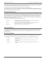
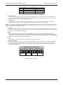
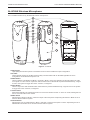
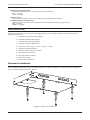
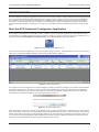
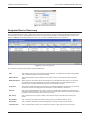
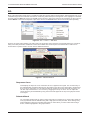
INSTALLATION INSTRUCTIONS LC372 SOUND REINFORCEMENT MODULE LC372SR SOUND REINFORCEMENT MODULE Installation Instructions REV: 10-12 DOC: 1307B LC372SR SOUND REINFORCEMENT MODULE INSTALLATION INSTRUCTIONS IMPORTANT SAFETY INSTRUCTIONS 1. 2. 3. 4. 5. 6. 7. 8. 9. 10. Read these instructions. Keep these instructions. Heed all warnings. Follow all instructions. Do not use this apparatus near water. Clean only with dry cloth. Install in accordance with the manufacturer’s instructions. Do not install near any heat sources such as radiators, heat registers, stoves, or other apparatus (including amplifiers) that produce heat. Only use attachments/accessories specified by the manufacturer. Refer all servicing to qualified service personnel. Servicing is required when the apparatus has been damaged in any way, such as power-supply cord or plug is damaged, liquid has been spilled or objects have fallen into the apparatus, the apparatus has been exposed to rain or moisture, does not operate normally, or has been dropped. SAFETY SYMBOLS Labeling on products and the Installation Instructions & User Manual may use safety related graphical symbols as shown below to note safety requirements. Lightning Bolt: The lightning flash with arrowhead symbol, within an equilateral triangle, WARNING symbol, is intended to alert the user to the presence of un-insulated dangerous voltage within the product’s enclosure that may be sufficient in magnitude to constitute a risk of electric shock to persons or domestic animals. Exclamation Point: The exclamation point within an equilateral triangle, CAUTION symbol, is in-tended to alert the user to the presence of important operating and maintenance (servicing) instructions, or a hazard that can damage equipment. Do not proceed beyond a WARNING or CAUTION notice until you have understood the hazardous condition and have taken appropriate steps. INTRODUCTION The LC372SR is a classroom sound reinforcement module designed for use in the IED LANcom SCS. The LC372SR utilizes wireless infrared microphones with an integrated receiver-audio mixer/amplifier to provide audio amplification in small to medium-sized applications like classrooms, libraries, lecture halls, small gymnasiums and auditoriums. The LC372SR has a line-level output to feed external devices such as hearing assistant systems, audio recorders or larger power amplifiers if it is used in a larger room such as a gymnasium. The Sound Reinforcement Module comes complete with 30 watt amplifier/receiver, infrared microphone, infrared sensor and charging station. It is controlled using a webbased interface for simplified configuration and use. It features no external knobs or switches to eliminate tampering or inadvertent system changes. All adjustments are made through IED’s LANcom SCS Software (LC300SWP) that allows teachers and end users to easily manage program source selection, individual component volume, muting and other functions after the installing contractor sets levels for emergency messages, bells and paging audio. Classroom sound reinforcement benefits teachers, guest lecturers, students and the education system as a whole. With even sound distribution, lessons are heard no matter where students are seated. Attention and concentration are raised, especially in the back of the room, through this added involvement. Teachers no longer strain their voice when using a wireless microphone and they can easily integrate with multimedia teaching tools such as computers and DVD players by controlling audio from a single source. With intercom, priority paging and emergency notification to inform another location of the need for outside assistance, IED LANcom SCS fulfills the needs of any education or large multifaceted facility. The LANcom SCS is a full system solution to meet the needs of all school districts. The flexible and wide array of products is designed to provide all the audio support needed no matter the application. The integrated receiver of the LC372SR is a 30W amplifier with a 25V speaker line. It features two (2) RJ45 connectors for use with LC11CS or LC12DCS wall plate call switches and LC372M remote intercom microphone. These standard call switches provide four logic input functions as normal call, emergency call, lockdown acknowledge, and contractor defined (i.e. CCTV or relay control). Four (4) relays are included; Relays 1 and 2 are for analog clock and time display synchronization and two (2) are for contractor defined relay for ancillary system integration via Phoenix/Euro block connector. The Sound Reinforcement Module also features four (4) auxiliary inputs; one (1) balanced input with mono summing on the back of the receiver through Phoenix/Euro block connector and three (3) via RJ45 connector on the LC372AI audio input plate- one (1) balanced XLR mic/line switchable, one (1) unbalanced stereo 3.5mm input with mono summing, and one (1) unbalanced stereo RCA input with mono summing. A separate RJ45 is included for connection to an intercom handset. A balanced, line level output is provided for connection to external audio amplifiers, hearing assistance systems or recording devices. Three infrared receivers can be connected to the amplifier to guarantee reliable connection and full coverage from the wireless IR microphone. PAGE 1 DOC: 1310B REV: 10-12 INSTALLATION INSTRUCTIONS LC372 SOUND REINFORCEMENT MODULE The LC372SR is powered via Ethernet cable from a LANcom power injector located near the device or in a remote telecommunications closet along with other data switch and distribution equipment. An internal fan and cabinet vents help keep the internal circuitry cool during operation. Contractor setup software tools are provided for device configuration and DSP adjustment. The LC372SR is controlled using standard web browsers on staff or administration computers. Controls include program input selection and volume for all local inputs and the selected program source. Wireless Microphone The LC372SR classroom sound reinforcement module is designed to work with the AtlasLearn infrared microphone. The versatile and ergonomic pendant/handheld microphone transmitter allows both teachers and students freedom of movement without bulky electronics or cumbersome wires. The dual mode transmitter allows teachers to control microphone volume, overall system volume and mute settings via side mounted soft touch controls. In addition, when PANIC and MODE controls are pressed simultaneously a contact closure is triggered that integrates with the rest of the IED LANcom SCS to signal an emergency condition in the classroom. The wireless microphone may be used in any of three configurations. Handheld Separate LED clusters located on top and bottom of unit guarantee optimum line of sight operation when the unit is handheld. Lanyard Secure connection features a safety breakaway function for easy release in an emergency and includes an innovative ID badge clip system. Body Pack Allows hands free use with optional headset mic. Charging Station The SRM also comes with a charging station for charging up to two (2) pendant transmitters and four additional AA rechargeable batteries simultaneously. The unit may be wall mounted via integral key hole slots or shelf mounted for easy accessibility. Mounting Options The LC372SR has the ability to be surface, rack, wall, or pole mounted. Four (4) rubber feet are included for surface mounting while other mounting options are accomplished with the use of one of the available optional kits: LC372RMK Rack Mount Kit for SRM for equipment rack mounting in 1RU, 15” minimum depth cabinets LC372WMK Wall Mount Kit for SRM for bracket mounting to walls, cabinets, or other vertical areas. LC372PMK Pole Mount Kit for SRM for mounting on standard projector poles up to 2” in diameter REV: 10-12 DOC: 1310B PAGE 2 LC372SR SOUND REINFORCEMENT MODULE INSTALLATION INSTRUCTIONS CONNECTIONS LC372SR Sound Reinforcement Module 1 LC372SR Figure 1 - LC372SR Front View 2 3 4 5 6 IR RECEIVER INPUTS CALL SWITCHES REMOTE MIC AUX INPUT HANDSET INTERFACE AUX AUDIO INPUT + - S + - S SPKR LINE OUT OUT MUTEPOWER + - S + - M V ETHERNET/ IED MIDSPAN FORM C RELAY OUTPUTS NC C NO NC C NO NC C NO NC C NO Model# LANcom LC372SR 7 8 9 10 11 12 Figure 2 - LC372SR Rear View 1. Power LED This LED will illuminate when power is applied to the unit. 2. Call Switches and Remote Microphone RJ45 Ports These ports are used to connect remote call switches (LC11CS or LC12DCS) or remote microphone modules (LC372M) to the unit. This port provides access to the four (4) control lines available for the call switches. The jumpers for each call switch determine which control line will be activated for each button. The four (4) control lines are shared (wired in parallel) between both ports. The microphone input is a buffered input, allowing simultaneous usage when a remote microphone module is connected to both ports. Both microphones are mixed to provide a single combined audio signal. Only one (1) LC372M may be connected to each port. PIN 1 Figure 3 - RJ45 Male Connector PAGE 3 DOC: 1310B REV: 10-12 INSTALLATION INSTRUCTIONS LC372 SOUND REINFORCEMENT MODULE Pin Function Cat5 Color Code 1 Audio + Orange /W 2 Audio Orange 3 Switch out * Green /W 4 Switch out * Blue 5 Switch out * Blue/W 6 Switch out * Green 7 +48 VDC Brown /W 8 Ground Brown * Signal pin is determined by jumper setting on call switch plates. Table 1 - Call Switch and Remote Microphone RJ45 Connector Wiring 3. Aux Input Port This port is used to connect to an LC372AI Audio Input Plate. This plate provides three (3) additional inputs to the system. Each plate contains the following inputs: • One balanced XLR mic/line switchable input • One unbalanced stereo input through a mono summing 3.5mm TRS jack • One unbalanced stereo mono summed input through two (2) RCA jacks Pin 1 2 3 4 5 6 7 8 Function RCA Audio + RCA Audio – 1/8” Jack Audio + XLR Mic/Line Audio + XLR Mic/Line Audio – 1/8” Jack Audio – +48 VDC Ground Cat5 Color Code Orange /W Orange Green /W Blue Blue/W Green Brown /W Brown Table 2 - RJ45 Connector Wiring 4. Handset RJ45 Port This port is used to connect an LC21HS Intercom Handset. When the LC21HS is lifted off its cradle switch, the intercom call switches into a private mode and disconnects the room microphone(s) and speaker and uses the microphone and speaker in the handset for a private intercom conversation. Once the handset is returned to the cradle switch, the room microphone(s) and speaker are restored. Pin 1 2 3 4 5 6 7 8 Function Handset Mic Output + Handset Mic Output – Hookswitch Out Handset Earphone Input + Handset Earphone Input – Hookswitch Out +48 VDC Ground Cat5 Color Code Orange /W Orange Green /W Blue Blue/W Green Brown /W Brown Table 3 - Handset RJ45 Connector Wiring 5. IR Receiver Inputs Up to three individual IR receivers can be connected to these ports to interface with the Atlas Learn IR microphones. These connectors can utilize the supplied cable or UL Listed RG59 coaxial cable with F-type fittings. The maximum cable length is 10m (32.8’). 6. Power and Network RJ45 Port This port is used to connect the LC372SR to the system network. It connects to the network through either an LC41PI or LC48MPI Power Injector that provides 48VDC power to the device. Note that power is provided only using the LC41PI or LC48MPI. This device is not compliant with PoE switches. Pin 1 2 3 4 REV: 10-12 Function Data Rx + Data RX – Data TX + +48V DC DOC: 1310B CAT5 Color Code Orange /W Orange Green /W Blue PAGE 4 LC372SR SOUND REINFORCEMENT MODULE Pin 5 6 7 8 INSTALLATION INSTRUCTIONS Function +48V DC Data TX – –48V DC (Ground) –48V DC (Ground) CAT5 Color Code Blue/W Green Brown /W Brown Table 4 - Power and Network RJ45 Connector Wiring 7. Aux Audio Input This connector provides an input for a balanced or unbalanced stereo (or mono) audio source. Both inputs are summed to mono and are controlled through the software. This input is ideal for connecting an audio source to the system when it is permanently installed in the room. 8. Speaker Out This connection is for the output of the power amplifier and used to connect to the local room loudspeaker or loudspeakers. This output is for 25V loudspeakers and has a maximum power output of 30W. NOTE: It is possible to use 70V loudspeakers with the 25V amplifier output, but the power factor for the transformer tap will be 1/8 of the listed tap setting. For example, a 70V loudspeaker tapped at 100W will only draw a maximum of 12.5W when connected to the 25V amplifier output. 9. Line Out This is a balanced line level output that can be used to connect to an external audio amplifier, hearing assistance system, or a recording device. The mix is the same as what is available at the speaker output, however this output does have its own output level adjustment. 10.Mute This is used to attach an external mute switch to the device. When a closure is present between the pins, all messages, live announcements, intercom calls, and bells will be muted in the room. Emergency messages will override the mute if it is active. This function is to give teachers the ability to place the system into a do not disturb mode for student testing or other special situations. 11.Power This terminal is not currently used and reserved for future implementation. IR RECEIVER INPUTS 12.Relay Output Jack The LC372SR has four Form C relays that are terminated at this connector. Relays 1 and 2 provide a momentary contact closure used to synchronize the clock in the room to the system time. The exact time and duration for this closure is globally configured in the control software at the headend. The functionsETHERNET/ of Relays 3 and 4 are configured in the software. IED MIDSPAN SPKR LINE OUT OUT MUTEPOWER + - S + - M V FORM C RELAY OUTPUTS NC C NO NC C NO NC C NO NC C NO Model# LANcom LC372SR Relay 1 Relay 2 Relay 3 Relay 4 Figure 4 - Relay Connector PAGE 5 DOC: 1310B REV: 10-12 INSTALLATION INSTRUCTIONS LC372 SOUND REINFORCEMENT MODULE AL-MYNA Wireless Microphone The LC372SR includes two (2) AL-MYNA IR wireless microphones. 13 14 15 16 17 22 18 23 19 24 20 21 25 26 14 Figure 5 - AL-MYNA 13.Microphone High quality internal microphone is used when the unit is in the handheld or lapel configuration. 14.IR LEDs These separate clusters of IR LEDs ensure quality c ommunications with an AL-IRDS regardless of which configuration the AL-MYNA microphone is in. 15.Mode Button Used to switch the AL-MYNA from Mode 1 or Mode 2. Mode 1 is the only operating mode supported in the LANcom system. It is also used in conjunction with the Panic button. When both are pressed simultaneously, a signal is sent to the system to trigger the “Panic” function, if configured. 16.Panic Button Used in conjunction with the Mode button. When both are pressed simultaneously, a signal is sent to the system to trigger the “Panic” function, if configured. 17.Power Button When the AL-MYNA is Off, holding this button for 3 seconds will turn the unit on. In the On mode, holding this button for 3 s econds will turn the unit Off. 18.Mute Button Depressing this button in Mode 1 mutes the o utput of the microphone. Depressing this button in Mode 2 has no function with the LANcom system. 19.Volume Button Depressing the UP or DOWN button in Mode 1 will raise or lower the microphone volume. Depressing the UP or DOWN button in Mode 2 has no function with the LANcom system. REV: 10-12 DOC: 1310B PAGE 6 LC372SR SOUND REINFORCEMENT MODULE INSTALLATION INSTRUCTIONS 20.Power LED Displays the battery power of the AL-MYNA. Green indicates good battery power. Red indicates low battery power. Off indicates the microphone is turned off. 21.Headset Microphone Input 3.5mm jack for connection of the optional AL-HSM headset microphone. The internal microphone is disabled when a headset is connected. 22.Mode LEDs These two LEDs indicate the current mode of the AL-MYNA. When the right side blue LED is illuminated, the unit is set to Mode 1. If both LEDs are illuminated, the unit is set to Mode 2. NOTE: The unit MUST be set to Mode 1 to work properly with the LANcom system. If the volume up/down button is not adjusting the microphone volume properly and you hear a pulsating noise through the loudspeakers, then the unit is probably set to Mode 2. Change the unit to Mode 1 using the Mode button to correct the problem. 23.Lockout Switch When this switch is set to the Lockout mode the unit works as a microphone only, no operation buttons function. Also referred to as “Student Mode”. 24.IR Channel Switch This slide switch sets the microphone channel “A” or “B”. 25.Belt Clip/Lanyard Clip Used to attached AL-MYNA to belt for headset configuration or to the included lanyard for a lapel configuration. 26.Battery Cover Conceals two “AA” rechargeable batteries, IR channel switch and Lockout mode switch. AL-MYNA-NEST The LC372SR includes one (1) AL-MYNA-NEST charging station for the two (2) included AL-MYNA IR wireless microphones. 27 28 30 29 Figure 6 - AL-MYNA-NEST 27.Microphone Charging Receptacles Holds the microphones in place while charging. The microphones can be placed in forwards or backwards. PAGE 7 DOC: 1310B REV: 10-12 INSTALLATION INSTRUCTIONS LC372 SOUND REINFORCEMENT MODULE 28.Microphone Charging LEDs These LEDs indicate the current charging status of each receptacle: Red = Charging, Green = Charged. 29.Battery Cover This provides a charging location for four additional rechargeable AA size batteries. 30.Additional Battery Charging LEDs These two LEDs indicate the current charging status of the additional battery charging locations: RED = Charging GREEN = Charged. INSTALLATION Unpack the LC372SR and accessories from the shipping carton. The LC372SR includes the following items that are packaged with the unit. 1 – LC372SR Sound Reinforcement Module 2 – AL-MYNA IR Wireless Microphones 1 – AL-MYNA-NEST Recharging Station 2 – Lanyards for Wireless Microphones 3 – Phoenix Connector Plugs (1 x 6-pin, 1 x 9-pin, 1 x 12-pin) 4 – Ni-MH Rechargeable Batteries 2 – 10M Interconnect Cables for AL-IRDS 2 – AL-IRDS IR Receiver Dome 2 – Mounting Plates for AL-IRDS 1 – 9VDC Power Supply 4 – Rubber Feet with Screws Standard Installation The LC372SR is supplied with four (4) removable rubber feet for standard installation on a shelf. Attach the rubber feet using the supplied screws as shown in Figure 7. Figure 7 - Rubber Feet Installation REV: 10-12 DOC: 1310B PAGE 8 LC372SR SOUND REINFORCEMENT MODULE INSTALLATION INSTRUCTIONS Optional LC372RMK Rack-Mount Installation Kit The LC372RMK is available as an optional accessory used to allow mounting the LC372SR in a standard 19” equipment rack. Attach the two rack ears as shown in Figure 8 using the mounting screws included with the kit. Figure 8 - LC372RMK Rack-Mount Installation Optional LC372WMK Wall-Mount Installation Kit The LC372WMK is available as an optional accessory used when installing the LC372SR on a wall or other flat surface. Attach the two mounting plates to the bottom of the unit as shown in Figure 9 using the screws supplied with the kit. Figure 9 - LC372WMK Mounting Plate Installation Attach the assembled unit to a wall or other suitable flat surface using screws that are suitable for the mounting surface. Note that these screws are not included. Take care to ensure that sufficient space is left around the unit to allow air flow through the ventilation openings and cool the unit. PAGE 9 DOC: 1310B REV: 10-12 INSTALLATION INSTRUCTIONS LC372 SOUND REINFORCEMENT MODULE Figure 10 - LC372WMK Wall-Mount Installation Optional LC372PMK Pole-Mount Installation Kit The LC372PMK is available as an optional accessory to mount the LC372SR on a pole of up to 2”. This is a convenient solution when mounting the device in a room that has a video projector suspended on a ceiling mount. This allows you to place the LC372SR on the mounting pole between the projector and the ceiling. The mounting hole is protected by two cover plates that must first be removed as shown in Figure 11. Figure 11 - LC372SR Cover Plate Removal REV: 10-12 DOC: 1310B PAGE 10 LC372SR SOUND REINFORCEMENT MODULE INSTALLATION INSTRUCTIONS Next, attach the mounting bracket as shown in Figure 12 using the supplied mounting screws. Insert the U-shaped pole brackets and attach the retaining nuts loosely as you will tighten them later. Figure 12 - LC372PMK Mounting Hardware Installation Slide the unit on the pole as shown in Figure 13 and tighten the U-shaped mounting clamps snugly to support the unit. Figure 13 - LC372PMK Pole-Mount Installation PAGE 11 DOC: 1310B REV: 10-12 INSTALLATION INSTRUCTIONS LC372 SOUND REINFORCEMENT MODULE Connect Unit to Other System Components Connect the field devices to the LC372SR as required. Figure 14 illustrates a typical room installation. Note that all connections are not shown in the example illustration. LC12DCS Call Switch LC12DCS Call Switch PB1 LC372AI Audio Input Plate PB1 J2 PIN 3 P IN 4 P IN 5 P IN 6 GND PB2 +48V PB2 MIC GAIN 1/8" JACK LO P1 INPUT 50d B OUTPUT HI LO P2 INPUT J1 26d B NO SHUNT = 6 dB GAIN PIN6 PIN5 PIN4 PIN3 PIN6 PIN5 PIN4 PIN3 OUTPUT LC372M Remote Microphone Module HI RCA PIN6 PIN5 PIN4 PIN3 PIN6 PIN5 PIN4 PIN3 LC372SR Sound Reinforcement Module LC21HS Intercom Handset IR RECEIVER INPUTS CALL SWITCHES REMOTE MIC AUX INPUT HANDSET INTERFACE AUX AUDIO INPUT + - S + - S SPKR LINE OUT OUT MUTEPOWER + - S + - M V ETHERNET/ IED MIDSPAN FORM C RELAY OUTPUTS NC C NO NC C NO NC C NO NC C NO Model# LANcom LC372SR LC41PI Power Injector Room Audio Source 1:36:24 6-1 A To Ethernet Switch Room Mute Switch 11 12 1 10 2 9 3 8 4 7 6 5 Room Clock AL-IRDS IR Receiver Dome Figure 14 - Installation Example REV: 10-12 DOC: 1310B PAGE 12 LC372SR SOUND REINFORCEMENT MODULE INSTALLATION INSTRUCTIONS CONFIGURATION The SCS Endpoint Configurator application provides access to all the necessary setup operations that must be performed on an LC372SR Sound Reinforcement Module before it can be used in a system. It also provides access to additional setup features, such as EQ, that are configured upon installation and not adjusted as part of normal system operation. This section covers the steps required to configure an LC372SR device and is not intended to provide comprehensive coverage of the SCS Endpoint Configurator tool. Refer to the included help file for additional information on the Configurator. Start the SCS Endpoint Configurator Application First, locate the SCS Endpoint Configurator on your computer. If you are using the system server, it should be located on the desktop or available and appear as the icon shown in Figure 15. If a shortcut is not present on the desktop, go to Explorer and look for SCS Endpoint Configurator.exe in the C:\IED\SRMICM Config Utility directory. Figure 15 - SCS Endpoint Configurator Icon Once you have located the application, open it by double-clicking on the icon. If the application is running on the system server, then you will immediately be taken to the discovery page shown in Figure 16 Figure 16 - Discovery Window It is possible to run the Configurator on a separate laptop or desktop computer to allow you to configure a device before it is installed in the system. The system server computer also maintains a service that is responsible for automatically assigning IP addresses to the devices in the system. If you are using a different computer, then this service will not be running and the Configurator will give you a warning as shown in Figure 17 Figure 17 - BOOTP Server Error Select Yes and the Configurator will run its own BOOTP server to assign IP addresses to the device(s) you will be configuring. After selecting Yes, you will see the BOOTP Options window as shown in Figure 18. Enter the range of IP address that the server will use by typing in a Start and Stop address. You must take care to ensure that this range is safe to use on your network. Enter the appropriate Subnet Mask and click the OK button. Selecting CANCEL at any time will close the window and the application will start without the BOOTP server running. PAGE 13 DOC: 1310B REV: 10-12 INSTALLATION INSTRUCTIONS LC372 SOUND REINFORCEMENT MODULE Figure 18 - BOOTP Server Options Endpoint Device Discovery Once the application is running, it will scan the network for any LANcom devices and they will appear in the Discovery Window as shown below. The application will poll the devices at an interval that is accessible through the menu bar Tools -> Options. The default polling interval is 5 sec. and this is suitable for most circumstances. Figure 19 - Discovery Window The columns in the Discovery Window are described below. Type This displays the type of device that has been detected. LC372SR devices will be of type SRM. This is a read-only field and cannot be edited. MAC Address This is the hardware network address of the device. This is a read-only field and cannot be edited. BOOTP Enabled When checked, this device will get its IP Address from the BOOTP server. When not checked, an IP Address must be manually typed in the IP Address field. For most applications, the BOOTP server should be utilized and this item should remain checked. IP Address This is the IP Address assigned to the device. If the BOOTP Enabled checkbox is not checked, an address can be manually typed into this field to set the address of the device. Node ID This is the unique identifier for the device. This is the number that will allow the LANcom SCS software to utilize this device. This is also the Zone number that is used to reference this device to program announcements, bells, and intercom calls. Mic Group This corresponds to the group number of the announcement controller that owns the mic station. Mic Number This is a unique mic station ID number used to assign mic stations within a group. Description This is a textual description to aid in identifying the device’s location and/or function. Last Response This is a date and time stamp to mark the last receipt of a poll response from the device. REV: 10-12 DOC: 1310B PAGE 14 LC372SR SOUND REINFORCEMENT MODULE INSTALLATION INSTRUCTIONS EQ Most of the adjustments made to the LC372SR are made through the LANcom SCS software. EQ adjustments are not accessible through the SCS software and must be made using the SCS Endpoint Configurator. First, highlight an LC372SR and then select the Edit sub-menu from the File menu as shown in Figure 20. There are two selections for PEQ. The one labeled Master is the main loudspeaker output of the device. The Line Out of the device can be adjusted separately. Figure 20 - File -> Device -> Edit Menu Figure 21 shows the PEQ window. The main section of the window is the response curve display where you can adjust many of the filter parameters. Additional controls are available at the bottom part of the window and a menu bar is located at the top that is used to access various additional features. Figure 21 - PEQ Edit Window Response Curve This displays the response curve of the filter set as it is applied to the signal. You can edit many of the individual filter parameters directly from the window using the mouse. Each filter is represented by a red dot on the graph. You can select the filter by clicking on the dot and it will turn green. You can then adjust the amount of cut or boost by dragging the dot up or down. You can adjust the center frequency and bandwidth by using the arrows that appear at the top of the graph as shown in the figure. Selected Band You can select the filter that you want to adjust using this row of buttons. For each output, there are nine (9) parametric bands available along with a high-pass and low-pass filter. Some settings may make it difficult to select the exact filter band that you want. When you select a filter band using a button, it will be highlighted in the graph window. PAGE 15 DOC: 1310B REV: 10-12 INSTALLATION INSTRUCTIONS LC372 SOUND REINFORCEMENT MODULE Center Freq. (HZ) Once you have selected a filter band, you can manually type in the frequency for the filter in this box. This allows you to quickly set the filter to a very precise value. When using one of the parametric bands, this frequency will control the center frequency of the filter. For the high-pass and low-pass filters, this will set the cutoff frequency. Gain (dB) Use this box to adjust the amount of cut or boost for the filter. This only applies to parametric filters and is not available for the high-pass and low-pass filters. You can also use the up and down arrow buttons to increment/decrement the value. Positive numbers will add gain to the filter and negative values will attenuate the filter. Bandwidth (Oct.) Use this box to manually input the bandwidth (in octaves) of the parametric filters. This will not affect the high-pass or low-pass filters. Filter Bypass This checkbox is only present for high-pass and low-pass filters. When checked, the filter will be bypassed. Set Flat Click this button to set the filter response curve to flat. This will remove any cut or boost applied using the parametric filters and set both the high-pass and low-pass filters to bypass. Close Click this button to close the window. All changes are made in real time, so you will not be prompted to save any changes. EQ Options Menu This menu provides access to the lesser-used options that change the EQ display. Legend Scale This will change the number of dB represented by each division of the scale, thus changing the vertical resolution of the graph. You may choose from 3dB/Div, 6dB/Div, 9dB/Div, or 12dB/Div. Frequency Scale This will change the way that the frequency (horizontal) axis is displayed. You can choose between Octave or Decade. Octave will display the axis in equal divisions while Decade will display the response curve in a logarithmic scale. 0dB Location This will set where on the graph the 0dB reference line is located. Available choices are Top, Mid Upper, Center, Mid Lower, or Bottom. Show Gain This will enable or disable the gain response curve on the graph as displayed by a blue line. Show Phase This will enable or disable the phase response curve on the graph as displayed by a magenta line. REV: 10-12 DOC: 1310B PAGE 16 LC372SR SOUND REINFORCEMENT MODULE INSTALLATION INSTRUCTIONS SPECIFICATIONS Mechanical Dimensions....................................................................8.50” W x 1.75” H x 13.625” D (215.9mm W x 44.5mm H x 346.1mm D) Mounting methods...................................Desk/Table Top Surface Mount (Standard), Optional Pole Mount Kit, Rack Mount Kit or Wall Mount Kit Connectors Ethernet/Power.....................................................................................................RJ-45 Call Switch/Remote Microphone.................................................................. RJ-45 (x2) Auxiliary Input Plate..............................................................................................RJ-45 Intercom Handset.................................................................................................RJ-45 Aux Audio Input (Back panel)............................................................. 6-pin Euroblock Speaker/Line Out, Mute In, & 48VDC Out .......................................... 8-pin Euroblock Relay Outputs.................................................................................... 12-pin Euroblock IR Sensors.............................................................................F-Connector Female (x3) Electrical Power...............................................................................................48VDC, 1.35A Max Provided via Ethernet Data Cable Input Sensitivity (Input 1)...................................................................................... 0dBu Input Sensitivity (Inputs 2-4)...............................................-3dBu (Left or Right Alone) 0dBu (Left and Right Summed) Speaker Output Maximum Output Power.......................................................................30 watts @ 25V Frequency Response..............................................................................22Hz – 22kHz S/N.........................................................................................................................97dB Line Output Maximum Output............................................................................................. +14dBu Frequency Response..............................................................................22Hz – 22kHz S/N.......................................................................................................................110dB Handset Output Maximum Output............................................................................................... +6dBu Frequency Response..............................................................................22Hz – 22kHz S/N.......................................................................................................................102dB Relay Outputs Contacts............................................................................................................ Form C Nominal Switching Capacity (resistive load)............................................2A @ 30VDC 0.5A @ 125VAC Transmitter Specifications IR Led’s........................................................................................... 6 Total in 2 Groups Aux Input.................................................................................................... 3.5mm, 2kΩ External Controls....................................................Power, Mode, Volume, Panic Mute Internal Controls......................................................... Channel A/B, Student Lock Out Mode Indicator LED’s......................................................................................Blue (x2) Lockout Indicator LED.............................................................................................Red PWR/BATT Indicator LED............................................................................ Green/Red Dimensions........................................................................1.8” W x 5.187” H x 1.31” D (45.7mm W x 131.7mm H x 33.4mm D) Weight (with Batteries)............................................................................4.23oz (120g) Weight (Less Batteries)...............................................................................2.1oz (60g) Charging Station Dock AL-MYNA Ports............................................................................................................ 2 Charge Indicator LED’s.................................... 4 (Red – Charging, Green – Charged) PSU Type.................................................................... 120V Input, 9VDC @ 1A Output Dimensions........................................................................7.44” W x 4.17” H x 2.75” D (189mm W x 106mm H x 70mm D) IR Receiver Dome Receiver LED’s............................................................................................................ 6 Mounting..................................................................................................... Screw Type Cable....................................................................................................UL Listed RG59 Termination..........................................................................................................F-type Maximum Cable Length..............................................................................32.8’ (10m) PAGE 17 DOC: 1310B REV: 10-12 INSTALLATION INSTRUCTIONS LC372 SOUND REINFORCEMENT MODULE NOTES REV: 10-12 DOC: 1310B PAGE 18 INSTALLATION INSTRUCTIONS Innovative Electronic Designs, LLC 9701 Taylorsville Road Louisville, KY 40299, USA REV: 10-12 LC372SR SOUND REINFORCEMENT MODULE +1.502.267.7436 phone +1.502.267.9070 fax www.iedaudio.com DOC: 1310B ©2012, Innovative Electronic Designs, LLC