1
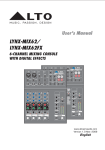
USER'S MANUAL
OEX-400S
STEREO FULL-RANGE COMPACT PORTABLE SOUND SYSTEM
WITH 24-BITS DIGITAL EFFECTS
MP3 PLAYER
MP3
USB REP
00
OEX-400s
PHANTOM
(CH1-4)
OFF
ALL
03 :08
ON
EQ
EQ
HI
EQ
HI
EQ
HI
WARM HALL
EQ
HI
BRIGHT HALL
REV+CHORUS 2
WARM ROOM
REV+CHORUS 1
HI
BRIGHT ROOM
REV+DELAY 4
-15
+15
-15
+15
-15
+15
-15
+15
-15
+15
-15
+15
-15
+15
-15
+15
VOCAL 1
REV+DELAY 3
VOCAL 2
REV+DELAY 2
REV+DELAY 1
VOCAL 3
STEREO+DELAY 2
LOW
LOW
LOW
LOW
LOW
PLATE
STEREO+DELAY 1
PRESETS
-15
+15
-15
+15
PEAK
DSP
/FX
DSP
/FX
DSP
/FX
DSP
/FX
POST
POST
POST
POST
POST
PAN
PAN
PAN
POWER
OUTPUT
LEVEL
MUTE
+10
+10
8
-
+10
8
-
+10
8
-
+10
8
-
+10
8
-
DSP
/FX
PAN
BAL
DSP
0
24 Bit digital effects
RIGHT
LEFT
RIGHT
LEFT
RIGHT
LEFT
LEFT
-
RIGHT
8
-10
RIGHT
LEFT
+10
LEVEL
-30
L
R
LEVEL
MIC
LEVEL
MIC
LINE
N
LOW OISE P
RE
LEVEL
MIC
LINE
N
LOW OISE P
RE
LEVEL
MIC
LINE
N
LOW OISE P
RE
+10
LEVEL
-
10
0
FX RET
+10
8
-
+10
8
-
+10
8
-
+10
8
-
+10
8
-
8
MASTER
LEVEL
PHONES
(MP3) LINE
LINE
N
LOW OISE P
RE
L
IN
R
P
AM
P
AM
P
AM
P
AM
L
LEFT(MONO)
FX RETURNS
MIC/LINE
MIC/LINE
MIC/LINE
MIC/LINE
RIGHT
FX SEND
1
2
3
4
5/6
(MIN. LOAD 4 Ohms)
R
L
OUT
R
CD/TAPE
SPK.OUT
SEIKAKU TECHNICAL GROUP LIMITED
NO. 1, Lane 17, Sec. 2, Han Shi West Road, Taichung 40151, Taiwan
http://www.altoproaudio.com Tel: 886-4-22313737
email: [email protected] Fax: 886-4-22346757
All rights reserved to ALTO. All features and content might be changed
without prior notice. Any photocopy, translation, or reproduction of part of this
manual without written permission is forbidden. Copyright c 2009 Seikaku Group
www.altoproaudio.com
Version 1.2 DEC. 2010
English
NF03374-1.2
9. WARRANTY
1. WARRANTY REGISTRATION CARD
To obtain Warranty Service, the buyer should first fill out and return the enclosed
Warranty Registration Card within 10 days of the Purchase Date.
All the information presented in this Warranty Registration Card gives the
manufacturer a better understanding of the sales status, so as to provide a
more effective and efficient after-sales warranty service. Please fill out all the
information carefully and genuinely, miswriting or absence of this card will void
your warranty service.
2. RETURN NOTICE
2.1 In case of return for any warranty service, please make sure that the product
is well packed in its original shipping carton, and it can protect your unit from
any other extra damage.
2.2 Please provide a copy of your sales receipt or other proof of purchase with
the returned machine, and give detail information about your return address
and contact telephone number.
2.3 A brief description of the defect will be appreciated.
2.4 Please prepay all the costs involved in the return shipping, handling and
insurance.
3. TERMS AND CONDITIONS
3.1 LTO warrants that this product will be free from any defects in materials
and/or workmanship for a period of 1 year from the purchase date if you
have completed the Warranty Registration Card in time.
3.2 The warranty service is only available to the original consumer, who purchased
this product directly from the retail dealer, and it can not be transferred.
3.3 During the warranty service, LTO may repair or replace this product at its
own option at no charge to you for parts or for labor in accordance with the
right side of this limited warranty.
3.4 This warranty does not apply to the damages to this product that occurred
as the following conditions:
Instead of operating in accordance with the user's manual thoroughly, any abuse
or misuse of this product.
Normal tear and wear.
The product has been altered or modified in any way.
Damage which may have been caused either directly or indirectly by another
product / force / etc.
Abnormal service or repairing by anyone other than the qualified personnel or
technician.
And in such cases, all the expenses will be charged to the buyer.
3.5 In no event shall LTO be liable for any incidental or consequential damages.
Some states do not allow the exclusion or limitation of incidental or
consequential damages, so the above exclusion or limitation may not apply to
you.
3.6 This warranty gives you the specific rights, and these rights are compatible
with the state laws, you may also have other statutory rights that may vary
from state to state.
20
8. TECHNICAL SPECIFICATION
FAT analysis
MP3 DECODE
Electric Specification
Power Section (SPK.OUT)
Distortion
Frequency Response
SNR (Line IN)
Output level
Power continuous 1KHz,THD 1%
Power EIAJ 1KHz,THD 1%
Thermal protection
Short protection
Voltage protection
Speaker Section
Passive System Type
Continuous Power
Peak Power
Max SPL at 1M
Frequency Response
Impedance
Crossover Frequency
Protection
Coaxial Type Low Frequency Driver
High Frequency Driver
Coverage HxV
Connectors
Statis Power Consumption
No Output powerstate at 230V
Dielectric Strength
Between Live+Negative Earth
Supports FAT 16 and FAT 32, Supports VFAT (long file
name), Supports multi-partion up to 1
Supports sample rates 8KHz, 32KHz, 11.025KHz,
22.05KHz, 44.1KHz, 12KHz, 24KHz, and 48KHz.
Supports bit rate 8 to 320 kbps and VBR (Variable Bi
Rate) except free format
Frequency Response 20Hz~20KHz
Output level 0 dB
S/N Ratio > 90 dB
Distortion (at 1 KHz) <0.05%
<0.1% (at 1W & 1 KHz)
<0.15% (at 100W & 1 KHz)
20Hz to 22kHz, +/-2dBu (at 100W)
100 dBu
30.5dBu +/-1dBu (+10 Led Light & COMP.Start)
2 X 200W @ 4
2 X 110W @ 8
2 X 250W @ 4
2 X 130W @ 8
over-temperature power limiting
thermal shutdown
Temperature controlled 12V DC fan output
short-circuit protection
overload output protection
over voltage protection
DC offset shutdown
2 -way Coax vented box
150W AES standard (each speaker)
300W Peak (each speaker)
117.5dB SPL calculated
65Hz-20KHz at -10dB
8 nominal
2.3KHz/12dB/Oct
Electronic on the Driver
10 Woofer / 2 Voice Coil
1 Neodymium Driver / 1 Voice Coil
70 Hx70 V Spherical hom
Power Input with mono Jack
32W
1500VAC at Test,Frequency 50/60Hz,Leakage
Current:5mA for 1minute
3000VAC at Test,Frequency 50/60Hz,Leakage
Current:5mA for 1minute
Between Live+Negative IN/OUT
Terminal(Positive+Negative)
Insulation Resistance
2M
Between Live+Negative
Earth(A Voltage of 500VDC)
4M
Between Live+Negative
IN/OUT Terminal(Positive+Negative)
(A Voltage of 500VDC)
Power supply
Main voltage
100-120VAC~60Hz
220-240VAC~50Hz
100~120V: T10A 250V
220~240V: T5A 250V
Physical
Dimension (W D H)
984mm*440mm*460mm (38.7 x17.3 x18.1 )
Net Weight
19.61kg
Cross Weight
25.41kg
19
IMPORTANT SAFETY INSTRUCTION
CAUTION
RISK OF ELECTRIC SHOCK
DO NOT OPEN
TO REDUCE THE RISK OF ELECTRIC SHOCK
PLEASE DO NOT REMOVE THE COVER OR
THE BACK PANEL OF THIS EQUIPMENT.
THERE ARE NO PARTS NEEDED BY USER
INSIDE THE EQUIPMENT. FOR SERVICE,
PLEASE CONTACT QUALIFIED SERVICE
CENTERS.
WARNING
To reduce the risk of electric shock
and fire, do not expose this equipment
to moisture or rain.
Dispose of this product should
not be placed in municipal waste
and should be separate collection.
11. Move this Equipment only with a cart,
stand, tripod, or bracket,
This symbol, wherever used, alerts you to the
specified by the
presence of un-insulated and dangerous voltages
manufacturer, or
within the product enclosure. These are voltages that
sold with the
may be sufficient to constitute the risk of electric
Equipment. When
shock or death.
a cart is used, use
This symbol, wherever used, alerts you to
caution when
important operating and maintenance instructions.
moving the cart /
Please read.
equipment
Protective Ground Terminal
combination to
AC mains (Alternating Current)
avoid possible
Hazardous Live Terminal
injury from tip-over.
ON: Denotes the product is turned on.
12. Permanent hearing loss may be caused by
OFF: Denotes the product is turned off.
exposure to \ extremely high noise levels.
CAUTION
The US. Government's Occupational Safety
Describes precautions that should be observed to
and Health Administration (OSHA) has
prevent damage to the product.
specified the permissible exposure to noise
1. Read this Manual carefully before operation.
level.
2. Keep this Manual in a safe place.
These are shown in the following chart:
3. Be aware of all warnings reported
with this symbol.
HOURS X DAY SPL EXAMPLE
4. Keep this Equipment away from water and
90 Small gig
8
moisture.
92 train
6
5. Clean it only with dry cloth. Do not use
95 Subway train
4
solvent or other chemicals.
97 High level desktop monitors
3
6. Do not damp or cover any cooling opening.
100 Classic music concert
2
Install the equipment only in accordance with
the Manufacturer's instructions.
102
1,5
105
1
7. Power Cords are designed for your safety. Do
110
0,5
not remove Ground connections! If the plug
does not fit your AC outlet, seek advice from
Rock concert
0,25 or less 115
a qualified electrician. Protect the power
According to OSHA, an exposure to high SPL in
cord and plug from any physical stress to
excess of these limits may result in the loss of
avoid risk of electric shock. Do not place
heat. To avoid the potential damage of heat, it is
heavy objects on the power cord. This could
cause electric shock or fire.
recommended that Personnel exposed to
equipment capable of generating high SPL use
8. Unplug this equipment when unused for long
hearing protection while such equipment is
periods of time or during a storm.
under operation.
Refer
all
service
to
qualified
service
personnel
9.
The apparatus shall be connected to a mains
only. Do not perform any servicing other than
those instructions contained within the
socket outlet with a protective earthing
User's Manual.
connection.
10. To prevent fire and damage to the product,
use only the recommended fuse type as
indicated in this manual. Do not short-circuit
the fuse holder. Before replacing the fuse,
make sure that the product is OFF and
disconnected from the AC outlet.
The mains plug or an appliance coupler is used
as the disconnect device, the disconnect device
shall remain readily operable.
IN THIS MANUAL
1.
2.
3.
4.
5.
6.
7.
8.
9.
INTRODUCTION................................................................................1
FEATURES.......................................................................................2
QUICK START..................................................................................2
CONTROL ELEMENTS......................................................................3
INSTALLATION & CONNECTION......................................................14
BLOCK DIAGRAM...........................................................................16
PRESET LIST..................................................................................17
TECHNICAL SPECIFICATIONS..........................................................18
WARRANTY..................................................................................20
1. INTRODUCTION
Congratulations! Now you are the owner of the OEX-400S. The OEX-400S is a
plastic reinforced trolley that includes a versatile mixer with DSP effects, L&R
full range speaker cabinets. Besides, this package also includes some essential
accessories such as power cord, signal cables, speaker cables. In order to
ensure high versatility and excellent audio performances, the OEX-400S adopts
optimal crossover frequency and advanced power amplifier technologies.
The L&R speaker cabinets are tightly hooked on the trolley. When you operate
the OEX-400S, first of all take care of the setting of the L&R cabinets . It is
the development of ALTO's experience and knowledge in speakers field, in order
to faithfully reproduce sound for each kind of applications.
Inlaid in OEX-400S panel there's a compact extractable 8-channel mixer, which
adopts 24-bit A/D&D/A converters and 24-bit DSP effects with accurate
algorithms (16 presets). It also provides 4 MIC inputs with ultra low noise
microphone pre-amplifiers, natural 2-band EQ; AUX send/return and 2TK in/out
and optional MP3 and 9 band EQ and so on.
In a word, it is ideally suited for live sound applications, small venues
applications, live recording and many other musical purposes. In order to get
the best performances from your OEX-400S, we recommend you to thoroughly read this owner's manual before installation and operation.
8. TECHNICAL SPECIFICATION
Mono channels(CH1-CH4)
Microphone Input
Frequency Response:
Distortion( THD&N)
Sensitivity
Maximum Voltage Gain
SNR( Signal to Noise Rate )
Phantom power
Line Input
Frequency Response:
Distortion( THD&N)
Sensitivity
Maximum Voltage Gain
Stereo channels(CH5/6)
Line Input
SNR( Signal to Noise Rate )
Frequency Response:
Distortion( THD&N)
Sensitivity
Maximum Voltage Gain
Impedance
Microphone Input
All Other Input
Tape Out
All Other Outputs
Equalization
High(Mono channels)
High(Stereo channels)
Low(Mono channels)
Low(Stereo channels)
DSP Section
A/D And D/A Converters
DSP Resolution
Type of effects
Presets
Controls
Crosstalk
Adjacent Input
Input to Output
Main Mix Section
TRACK,Aux,Phones Output
Master Output(to AMP)
Main EQ(Option)
Noise (Bus noise)
Compressor
Threshold
Ratio
Mp3 Section(Option)
USB HOST
1
Electronically Balanced, discrete Input Configuration(SW
to MIC)
20Hz to 22kHz, +/-2dBu
0.02% At 1kHz
-30 dBu
51 dB CH MIC INPUT HEAD PHONE OUT
51 dB CH MIC INPUT TAPE OUT
51 dB CH MIC INPUT FX SEND
100 dBu
+45V~+49V with switch control (Mic Pin2/Pin3 And Pin1)
Electronically Balanced(SW to LINE)
20Hz to 22kHz, +/2dBu
0.02% At 1kHz
0 dBu
21 dB CH LINE INPUT TAPE OUT
Electronically Balanced(SW to LINE)
100 dBu
20Hz to 22kHz, +/-2dBu
0.02% At 1kHz
0 dBu
20 dB FX RETURN TAPE OUT
20 dB RCA TAPE INPUT TAPE OUT
3.9k Ohms
10k Ohms or Greater
1k Ohms
120 Ohms
15
15
15
15
dB
dB
dB
dB
@12
@12
@80
@80
kHz
kHz
Hz
Hz
24 Bit
24 Bit
WARM HALL, BRIGHT HALL, WARM ROOM, BRIGHT
ROOM, VOCAL1, VOCAL2, VOCAL3, PLATE, STEREO
DELAY1, STEREO DELAY2, REV+DELAY1, REV+DELAY2,
REV+DELAY3,REV+DEALY4,REV+CHORUS1,REV+
CHORUS2
16
16-Posistion PRESET Selector
CLIP LED
MUTE SWITCH with LED Indicator
-75 dB @ 1KHz (CH1-6)
-70 dB @ 1KHz (STEREO L/R,CH1-4,PAN:panned hard
left or right)
Output level 0dBu Unbalanced, 1/4" Jacks
Max out +22dBu Unbalanced, 1/4" Jacks
Output level -5dBu (CN10,CN11)
+/-12dB @ 9 bands(63,125,250,500,1K,2K,4K,8K,16KHz)
-78dB @ 20Hz~22KHz (channel & MAIN level at 0dB,
other at minimum,DSP mute)
7dBu
6:1
"Builds in the USB FULL speed(12Mbps)HOST
control function"
Supports the USB mass storage class
18
2. FEATURES
7. PRESET LIST
NO.
Preset
Description
Parameter
1
WARM HALL
Simulate a small acoustic space of the sound.
Rev. Decay time: 360ms
Pre-delay: 45ms
2
BRIGHT HALL
Simulate a large acoustic space of the sound.
Rev. decay time: 290ms
Pre-delay: 23ms
3
WARM ROOM
Simulate a small acoustic space of the sound.
Rev. decay time: 210ms
Pre-delay: 45ms
4
BRIGHT ROOM
Simulate a studio room with many early reflections.
Rev. Decay time: 210ms
Pre-delay: 23ms
5
VOCAL 1
Simulate a room with without delay time.
Rev. decay time: 450ms
6
VOCAL 2
Simulate a room with small delay time.
Rev. decay time:240ms
Pre-delay: 25ms
7
VOCAL 3
Simulate a small space with slight decay time.
Rev. decay time:100ms
Pre-delay: 114ms
8
PLATE
Simulate the transducers sound like classic bright
vocal plate.
Pre-delay: 10ms
Rev. decay time: 290ms
9
STEREO DELAY 1
Recreate the input sound on the stereo output
with different time.
Period: 352ms
10 STEREO DELAY 2
Recreate the input sound on the stereo output
with different time.
Period: 238ms
11 REV+DELAY 1
Delay with room effect.
Delay period: 326ms
Rev. decay time: 290ms
12 REV+DELAY 2
Delay with room effect.
Delay period: 211ms
Rev. decay time: 240ms
13 REV+DELAY 3
Delay with room effect.
Delay period: 375ms
Rev. decay time: 210ms
14 REV+DELAY 4
Delay with room effect.
Delay period: 277ms
Rev. decay time: 150ms
15 REV+CHORUS 1
Simulate the sound effect achieved by rotating
horn speakers and a bass cylinder.
Chorus rate: 3.67Hz
Rev. decay time: 290ms
16 REV+CHORUS 2
Simulate the sound effect achieved by rotating
horn speakers and a bass cylinder.
Chorus rate: 3.02Hz
Rev. decay time: 150ms
Lightweight, Luggage style, Trolley appearance portable system
Two 10" speakers + 8-channel powered mixer in super combination
Stereo full-range speaker system
4 XLR MIC input with ultra low noise microphone pre-amplifiers
+48V Phantom power
1 stereo LINE input & 1 stereo CD/TAPE input
Warm, natural 2-band EQ , PAN(BAL) for each channel
Precision level control
24-bit DSP effects with powerful algorithms (16 presets)
MP3 player & 9-Band EQ for option
2 speaker cables & 2 microphone and cables
Amp. System with 250W *2 @ 4ohm in EIAJ; 200W * 2 @ 4ohm in RMS
3. QUICK START
This is the fastest way to get something out from your OEX-400S, if you have
a keyboard and a microphone.
a. Please check the AC voltage available in your country before connecting your
OEX-400S to the AC socket.
b. Be sure that the main power switch is turned off before connecting the
powered mixer to the AC socket. Also, you should make sure that all input
and output controls are turned down. This will avoid damages to your
speakers as well as excessive noise.
c. Please connect a passive speaker to your OEX-400S speaker connector or
1/4'' jack(#35). Otherwise, you can connect a pair of active speakers directly
to your OEX-400S Main Out Left & Right 1/4'' jacks(#18).
d. Complete these connections as illustrated.
e. Before disconnecting the OEX-400S always turn-off the Power switch.
f. Do not use solvents to clean your OEX-400S. A dry and clean cloth will be OK.
Here you are. It is your first GIG with your OEX-400S.
17
2
SP
OT
L
IG
GIG HOOKUP DIAGRAM
6. BLOCK DIAGRAM
HT
USB key
MP3 PLAYER
MP3
USB REP
00
OEX-400s
PHANTOM
(CH1-4)
OFF
ALL
03 :08
ON
EQ
EQ
EQ
EQ
EQ
HI
HI
HI
HI
HI
WARM HALL
BRIGHT HALL
REV+CHORUS 2
WARM ROOM
REV+CHORUS 1
BRIGHT ROOM
REV+DELAY 4
-15
+15
-15
+15
-15
+15
-15
+15
-15
VOCAL 1
REV+DELAY 3
+15
VOCAL 2
REV+DELAY 2
REV+DELAY 1
VOCAL 3
STEREO+DELAY 2
LOW
LOW
LOW
LOW
LOW
PLATE
STEREO+DELAY 1
PRESETS
-15
+15
-15
+15
-15
+15
-15
+15
-15
+15
PEAK
DSP
/FX
DSP
/FX
DSP
/FX
DSP
/FX
POST
POST
POST
POST
POST
MUTE
BAL
DSP
PAN
PAN
PAN
OUTPUT
LEVEL
+10
+10
8
-
+10
8
-
+10
8
-
+10
8
-
+10
8
-
POWER
DSP
/FX
PAN
0
24 Bit digital effects
RIGHT
LEFT
RIGHT
LEFT
RIGHT
LEFT
LEFT
-
RIGHT
8
-10
RIGHT
LEFT
+10
LEVEL
-30
L
R
LEVEL
MIC
LEVEL
LINE
MIC
N
LOW OISE P
RE
LEVEL
LINE
MIC
N
LOW OISE P
RE
LEVEL
LINE
MIC
N
LOW OISE P
RE
+10
LEVEL
-
10
0
FX RET
HEADPHONE
+10
8
-
+10
8
-
+10
8
-
+10
8
-
+10
8
-
8
MASTER
LEVEL
PHONES
(MP3) LINE
LINE
N
LOW OISE P
RE
L
IN
R
P
AM
P
AM
P
AM
P
AM
L
LEFT(MONO)
FX RETURNS
(MIN. LOAD 4 Ohms)
R
MIC/LINE
MIC/LINE
MIC/LINE
MIC/LINE
RIGHT
1
2
3
4
5/6
FX SEND
L
OUT
R
CD/TAPE
SPK.OUT
SPEAKER
DAT
DAT OR TAPE RECORDER
MIC1
WIRELESS
MICROPHONE
DIGITAL EFFECT UNIT
MIC2
BASS
3
KEYBOARD
16
5. INSTALLATION AND CONNECTION
SP
OT
L
IG
OEX-400S
HT
Ring=Return Signal (Connected together)
To Channel Insert
Sleeve=Ground/Screen
OPTION
Tip=Signal
OEX-400s
PHANTOM
(CH1-4)
OFF
ON
To Tape or FX Input
EQ
EQ
EQ
EQ
EQ
HI
HI
HI
HI
HI
WARM HALL
BRIGHT HALL
REV+CHORUS 2
WARM ROOM
REV+CHORUS 1
BRIGHT ROOM
REV+DELAY 4
-15
+15
-15
+15
-15
+15
-15
+15
-15
VOCAL 1
REV+DELAY 3
+15
VOCAL 2
REV+DELAY 2
Sleeve=Ground/Screen
REV+DELAY 1
VOCAL 3
STEREO+DELAY 2
LOW
LOW
LOW
LOW
LOW
PLATE
STEREO+DELAY 1
PRESETS
-15
+15
-15
+15
-15
+15
-15
+15
-15
+15
PEAK
POWER
DSP
/FX
DSP
/FX
DSP
/FX
DSP
/FX
DSP
/FX
POST
POST
POST
POST
POST
MUTE
BAL
DSP
-
+10
PAN
OUTPUT
LEVEL
+10
+10
8
-
+10
PAN
8
-
+10
PAN
8
-
+10
8
-
8
'Tapped' Connection Direct Output Lead
(Enables the Insert to be used as a Direct Output
while maintaining the channel signal flow)
PAN
0
24 Bit digital effects
RIGHT
LEFT
RIGHT
LEFT
RIGHT
LEFT
LEFT
-
RIGHT
8
-10
RIGHT
LEFT
+10
LEVEL
-30
L
R
LEVEL
To Processor Input
MIC
LEVEL
MIC
LINE
N
LOW OISE P
RE
LEVEL
MIC
LINE
N
LOW OISE P
RE
LEVEL
MIC
LINE
N
LOW OISE P
RE
+10
LEVEL
-
10
0
FX RET
+10
8
-
+10
8
-
+10
8
-
+10
8
-
+10
8
-
8
MASTER
LEVEL
PHONES
(MP3) LINE
LINE
N
LOW OISE P
RE
L
IN
R
P
AM
P
AM
P
AM
P
AM
L
LEFT(MONO)
FX RETURNS
(MIN. LOAD 4 Ohms)
R
Sleeve=Ground/Screen
Tip=Send Signal
MIC/LINE
MIC/LINE
MIC/LINE
MIC/LINE
RIGHT
1
2
3
4
5/6
FX SEND
L
OUT
R
CD/TAPE
SPK.OUT
Tip
To Channel Insert
Sleeve
Ring
Ring=Return Signal
MP3 PLAYER
MP3
00
USB REP
03 :08
To Processor Output
Y-Stereo lead for insert Connection
(To be used when the processor does not employ a
single jack connection for the In/Out Connections)
Option NO.1
63
125
250
500
1K
2K
4K
8K
16K
+12
+12
+8
+8
+4
+4
0
0
-4
EQ OFF
EQ ON
USB Connection
ALL
-4
-8
-8
-12
-12
STEREO GRAPHIC EQ
Option NO.2
15
4
SP
OT
L
IG
5. INSTALLATION AND CONNECTION
4. CONTROL ELEMENTS
HT
Accessory List:
1
2
3
4
5
6
Power cord
Customized Speaker Cable
MIC
F-8 stands (optional)
F-3 stands (optional)
F-3 stand adaptor (optional)
Audio Connections
You can connect unbalanced equipment to balanced inputs and outputs. Simply
follow these schematics.
1 IEC power cord
2 7m
2 5m
Sleeve
Tip
Ring
Ring=Right Signal
Tip=Left Signal
Strain Clamp
Sleeve=Ground/Screen
Use for Headphone
1/4" Stereo (TRS) Jack Plug
Sleeve
Tip
Tip=Signal
Strain Clamp
1
2
3
Sleeve=Ground/Screen
Use for Mono Line In, Mono 1/4"Jack Plugs
OFF
1/4" Mono (TS) Jack Plug
OEX-400s
PHANTOM
(CH1-4)
ON
EQ
EQ
HI
EQ
HI
EQ
HI
WARM HALL
EQ
HI
BRIGHT HALL
REV+CHORUS 2
WARM ROOM
REV+CHORUS 1
HI
BRIGHT ROOM
REV+DELAY 4
-15
+15
-15
+15
-15
+15
-15
+15
-15
+15
-15
+15
-15
+15
-15
+15
-15
+15
-15
+15
VOCAL 1
REV+DELAY 3
VOCAL 2
REV+DELAY 2
REV+DELAY 1
VOCAL 3
STEREO+DELAY 2
LOW
LOW
LOW
LOW
LOW
PLATE
STEREO+DELAY 1
PRESETS
PEAK
DSP
/FX
POST
PAN
POST
-
+10
PAN
POWER
DSP
/FX
POST
-
+10
8
-
+10
8
8
DSP
/FX
POST
-
PAN
OUTPUT
LEVEL
MUTE
+10
+10
8
DSP
/FX
POST
+10
8
DSP
/FX
-
PAN
BAL
DSP
0
24 Bit digital effects
RIGHT
LEFT
RIGHT
LEFT
RIGHT
LEFT
RIGHT
LEFT
LEFT
-
RIGHT
8
-10
+10
LEVEL
-30
L
R
LEVEL
MIC
LINE
LEVEL
MIC
LINE
N
LOW OISE P
RE
LEVEL
MIC
LINE
N
LOW OISE P
RE
+10
LEVEL
0
-
10
FX RET
+10
8
-
+10
8
-
+10
8
8
-
+10
8
-
+10
LEVEL
N
LOW OISE P
RE
8
MASTER
-
MIC
LEVEL
PHONES
(MP3) LINE
LINE
N
LOW OISE P
RE
IN
R
L
OUT
R
P
AM
P
AM
P
AM
P
AM
L
L
LEFT(MONO)
FX RETURNS
MIC/LINE
MIC/LINE
MIC/LINE
MIC/LINE
RIGHT
FX SEND
1
2
3
4
5/6
Ring=Return Signal
(MIN. LOAD 4 Ohms)
R
CD/TAPE
Sleeve
SPK.OUT
Tip
Ring
Strain Clamp
Tip=Send Signal
6
Sleeve=Ground/Screen
5
Use for Insert Points
1/4" Stereo (TRS) Jack Plug
4
4
2=Hot(+)
5
2
3
1
1=Ground/Screen
2=Hot(+)
2
3
1
1=Ground/Screen
3=Cold(-)
3=Cold(-)
Use for Balanced Mic Inputs
(For unbalanced use, connect pin 1 to 3)
Use for Main output
(For unbalanced use, leave pin3 unconnected)
3-pin XLR Male Plug
3-pin XLR Line Socket
(seen from soldering side)
(seen from soldering side)
14
SP
OT
L
IG
SP
4. CONTROL ELEMENTS
HT
9 BAND EQ selective mode
63
125
250
500
1K
2K
4K
8K
EQ MODULE
16K
+12
+12
EQ OFF
EQ ON
+8
+8
+4
+4
0
0
-4
-4
-8
-8
-12
-12
CN7
STEREO GRAPHIC EQ
CN9
Please connect the 8PIN row-wire on the 9BAND EQ model to the CN9 header
on the main mixer board. Then fix the 9BAND EQ model on the mixer panel with
two screws.
34 POWER ON/OFF
This switch is used to turn the main power on/off.
35 AC SELECT
Before connecting the OEX-400S to the mains supply first check that the
Voltage Selector is showing the correct voltage for your country.
36 AC INLET
This jack is used to connect the unit to
the mains with the enclosed power cord.
(Depends on applicable country regulators)
34
35
POWER
AC SELECT
36
AC INPUT
ON
OFF
OT
L
IG
4. CONTROL ELEMENTS
HT
1 PHANTOM POWER Switch
This button will apply +48 Volt Phantom
Power only to the 4 XLR MIC input sockets.
When condenser microphones are not used,
please make sure that the Phantom Power
is disengaged.
NOTE: When switch on/off the phantom power,
please firstly turn the level control knob to min.
PHANTOM
(CH1-4)
1
OFF
ON
9
10
2 MONO INPUT CHANNELS(CH1 TO CH4)
There is CH1 through CH4, which comes with
balanced MIC IN and LINE IN connectors. Use
the XLR (MIC IN) socket to connect low impedance microphone or low level signal. Use the
1/4" TRS (LINE IN) jack to connect either a
microphone or a line level instrument such as
synthesizers, drum machines, effect processors or any other line level signal.
NOTE: Never try to connect a line-level signal
to the XLR MIC input when the phantom power
is engaged or you may seriously damage your
equipment.
3 STEREO INPUT CHANNEL(CH5/6)
These are channels 5/6. They are organised
in stereopair and provided with 1/4" TRS
phone sockets. If you connect only the left
jack, the input will operate in mono mode,
that is the mono signal will appear on both
input channels. You can use these inputs
with a stereo keyboard, drum machine, etc.
8
7
6
4
5
3
1
2
100-120V~60Hz FUSE: T10AL 250V
220-240V~50/60Hz FUSE: T5AL 250V
4 MIC / LINE switch
When using XLR socket, please put the switch at the MIC position; When using
1/4'' TRS jack, please put the switch at the LINE position.
5 MP3/LINE switch
Pushing this switch to left will route the signal from MP3 IN to CH5/6 path,
while to right will route the signal from 1/4'' TRS jack.
6 LEVEL CONTROL
This control is used to adjust the overall level of respective Channel. The adjustable range goes from - to +10dB.
13
6
OT
L
IG
SP
4. CONTROL ELEMENTS
HT
7 PAN/BAL CONTROL
This is the PANORAMA control, or balance control. You can adjust the stereo
image of the signal via this control. Keep this control in center position and
your signal will be positioned in the middle of stage. Turn this control fully
counter clockwise and the signal will be present only on the left speaker and
vice-versa. Of course a large number of intermediate positions is available.
8 DSP/FX control
This control is configured as POST-FADER, so the audio signal will be affected
by channel level control. Via the FX SEND socket, the AUX1 signal can be sent
to an external effect device.
OT
L
IG
4. CONTROL ELEMENTS
HT
U
SP
MP3
US
When the player is searching for Mp3 songs, the interface is as follows:
NORMAL
When the player is in pause state, the interface is as follows:
ooo
MP3
EQUALIZER
Your OEX-400S features a 2-band equalizer allowing you to adjust the high and
low frequencies separately on each mono channel. Both bands provide up to
+15dB of boost or cut.
10 LOW
This is the bass control. It is used to boost male voice or kick-drum and bass
guitar. Your system will sound much bigger than what it is. The gain range
goes from -15dB to +15dB and the center frequency is 80Hz.
11
USB ERP
ALL
NORMAL
When the player is in use, the interface is as follows:
ooo
MP3
9 HIGH
This is the treble control. You can use it to get rid of high frequency noises or
to boost the sound of cymbals or the high harmonics of the human voice. The
gain range goes from -15dB to +15dB with a center frequency of 12kHz.
NORMAL
USB ERP
ALL
S
NORMAL
MP3 and 9 BAND EQ selective mode section(Option)
No selective mode
JUMPER
CN7
CN9
At normal state, there is no selective mode on the front panel, only a piece of
panel without any painting and function. But there are two selective modes for
what you like, that is MP3 mode and 9 BAND EQ mode. Please note that on
the main mixer board, there is a short circuit row-wire in the CN9 header.
Mp3 selective mode
12
13
DSP SECTION
Your OEX-400S features the special 16-preset digital effect, further details
please refer to following content.
7
MP3
00
USB REP
JUMPER
MP3 MODULE
MP3 PLAYER
ALL
03 :08
CN7
CN9
Please connect the 5PIN row-wire on the MP3 model to the CN7 header on
the main mixer board. Put the provided 8PIN short circuit row-wire in the CN9
header on the main mixer board. Then fix the MP3 model on the mixer panel
with two screws.
12
IG
4. CONTROL ELEMENTS
HT
27
1 USB PORT
For connecting with USB memory.
28
1 PREVIOUS
In pause state, press this button it will go to the previous song and keep
in pause state. In play state, press this button it will go to the previous song
and start playing.
29
1 NEXT
In pause state, press this button it will go to the next song and keep in
pause state. In play state, press this button , it will go to the next song
and start playing.
30
1 REPEAT
Press this button the player will change between the following four modes. REP
ALL means to repeat all songs in the memory, the mark on the screen is all .
REP1 means to repeat one song, the mark on the screen is 1 . Play in order
means to play the songs according to the order, the mark on the screen is
blank. Random play means to play the songs at random, the mark on the
screen is A.
SP
OT
L
IG
4. CONTROL ELEMENTS
HT
11 PRESETS
Adjust this knob to select the right effect you wish to perform. There are total
16 options for you: WARM HALL,BRIGHT HALL, WARM ROOM, BRIGHT ROOM,
VOCAL 1, VOCAL 2, VOCAL 3, PLATE, STEREO DELAY1,STEREO DELAY2, REV
+ DELAY1, REV + DELAY2, REV + DELAY3, REV + DELAY4, REV + CHORUS1
and REV + CHROUS2.
12 PEAK/MUTE LED
This LED lights up when the input signal is too strong. In case of the digital
effect module being muted, this LED also lights up.
13 DSP MUTE SWITCH
This switch is used to activate/deactivate the effect facility.
POWER
14
OUTPUT
LEVEL
+10
0
21
16
-10
-
32
1 STOP
In play state, press STOP button to stop playing and the whole quantity
of Mp3 songs in the USB memory will display on the screen. In STOP
state, press the PRE/NEXT button or press the STOP button again to go
to the first songs and the player will keep in pause state, then press
down the PLAY/PAUSE button to play it.
33
1 POWER
When the unit is off, press this button and hold for about 2 or 3 seconds to
turn on the power supply of the player. Repeat the above operation, you can
turn off the power supply of the player.
+10
LEVEL
-30
L
18
R
MASTER
0
31
1 PLAY/PAUSE
In play state, press PLAY/PAUSE button to pause the player. In pause state,
press PLAY/PAUSE button to start playing.
8
OT
L
-
10
FX RET
15
+10
8
SP
LEVEL
PHONES
23
20
L
IN
R
17
L
FX RETURNS
(MIN. LOAD 4 Ohms)
19
R
FX SEND
L
OUT
R
CD/TAPE
SPK.OUT
22
24
14 POWER LED
When you switch on the apparatus,the LED will light on.
15 MASTER LEVEL CONTROL
This control is used to adjust the overall volume of main mix output, and the
signal also input to the preamplifier.
NOTE: Basic interface instruction.
When the player isn't connected to a USB memory equipment, the interface
is as follows:
11
16 MASTER LEVEL LED
The 4-segment LED metre is used to indicate the master output level. When
the red LED lights on, it means that the MIX OUT reaches +10dB, or start
the compressor from the build in AMP.
8
SP
OT
L
IG
4. CONTROL ELEMENTS
HT
17 FX RTN. Jack
Use the stereo phone jack to return the sound of an effect unit to the main
mix. You can also use it as a extra auxiliary stereo input.
18 FX RET CONTROL
This control is used to control the volume of the processed signal sent to
Main Mix bus, which can be varied from - to+10 dB.
SP
OT
L
IG
4. CONTROL ELEMENTS
HT
9 Band EQ section (Optional)
25 EQ Switch
Engage this button to add the stereo graphic EQ to the main mix output
circuit.It can be used to modify the frequency "contour" of a sound. If you
release the button, the stereo graphic EQ will be bypassed.
26 STEREO GRAPHIC EQ
19 FX SEND
This jack is used to send out the signals from AUX bus.
20 CD/TAPE IN
Use the Tape input to connect a CD Player, Tape, DAT, iPOD or any other linelevel source.
21 CD/ TAPE LEVEL CONTROL
This knob controls the signal sent from CD/TAPE IN,which can be varied from
- to+10 dB.
Each one of these faders will boost or attenuate (+/-12 dB) the selected frequency
at a preset bandwidth. When all the faders are in the center position, the output
of the equalizer is flat response.
63
125
250
500
4K
25
EQ OFF
EQ ON
8K
16K
+12
+8
+8
+4
+4
0
0
-4
-4
-8
-8
-12
-12
STEREO GRAPHIC EQ
23 PHONES
This socket will be used to send the signal to a pair of headphones.
Connecting two speakers
2K
+12
22 CD/TAPE OUT
These RCA jacks will route the main mix signal into a tape or DAT recorder.
24 SPK. OUT
The SPEAKER L&R phone jacks output the main signal from the internal power
amplifier and are used to connect speakers. They are internally connected in
parallel and output the same signal.
1K
26
MP3 section (Optional)
The file system of USB memory for USB-MP3 player is FAT16 and FAT32. The
player can only decode MP3. It can have 7 rank subordinate folders at most,
and the maximum quantity of folders within MP3 files is 24. In the whole USB
memory, the total folders can not beyond 256(incluing those folders without
MP3 songs).
28
27
29 30
MP3 PLAYER
MP3
00
USB REP
ALL
03 :08
4~8
Note: The total impedance of the connected speaker system must be between
4 and 8 ohms. Do not connect anything other than speakers to these jacks.
9
31 32 33
10