1
G50 / G50-8 GAS RANGE
SERVICE MANUAL
Revision 3/F3601
-1-
WARNING: ALL INSTALLATION AND SERVICE REPAIR WORK MUST BE CARRIED
OUT BY QUALIFIED PERSONS ONLY.
Revision 3/F3601
-2-
CONTENTS
This manual is designed to take a more in depth look at the G50 gas ranges for the purpose of
making the units more understandable to service people.
There are settings explained in this manual that should never require to be adjusted, but for
completeness and those special cases where these settings are required to change, this manual
gives a full explanation as to how, and what effects will result.
SECTION
PAGE NO.
1.
SPECIFICATIONS ........................................................................................................ 5
2.
INSTALLATION ............................................................................................................ 8
3.
OPERATION ................................................................................................................. 10
3.1
3.2
Operation
Explanation of Control System
4.
MAINTENANCE ............................................................................................................ 12
5.
TROUBLE SHOOTING GUIDE..................................................................................... 13
5.1
5.2
6.
Hob
Oven
SERVICE PROCEDURES............................................................................................. 17
6.1
6.2
6.3
6.4
Fault Diagnosis
Access
Replacement
Adjustment / Calibration
7.
SPARE PARTS ............................................................................................................. 31
8.
PARTS DIAGRAM ........................................................................................................ 32
8.1
8.2
9.
Main Assembly
Gas Piping Assembly
SERVICE CONTACTS .................................................................................................. 38
IMPORTANT: MAKING ALTERATIONS MAY VOID WARRANTIES AND APPROVALS.
Revision 3/F3601
-3-
Revision 3/F3601
-4-
1. SPECIFICATIONS
MODEL: G50
G50 A
G50 B
G50 C
G50 D
LEGEND
- Gas connection entry point - ¾” BSP male
Dimensions shown in millimetres.
Revision 3/F3601
-5-
MODEL: G50-8
G50-8 A
G50-8 B
G50-8 C
G50-8 D
LEGEND
- Gas connection entry point - ¾” BSP male
Dimensions shown in millimetres.
Revision 3/F3601
-6-
INSTALLATION CLEARANCES
Non-Combustible
0 mm
25 mm
Sides
Back
OVEN INTERNAL DIMENSIONS
Combustible
25 mm
25 mm
Height
Width
Depth
CATEGORY
I2H, I3P
HEAT INPUT
Input
G50 D
G50 C
G50 B
G50 A
36.0 kW
31.5 kW
27.0 kW
22.5 kW
Gas Rate
G20
G31
3.45 m³/h 2.54 m³/h
3.02 m³/h 2.22 m³/h
2.59 m³/h 1.89 m³/h
2.16 m³/h 1.57 m³/h
G50-8 D
G50-8 C
G50-8 B
G50-8 A
46.0 kW
41.5 kW
37.0 kW
22.5 kW
4.41 m³/h
3.98 m³/h
3.55 m³/h
3.12 m³/h
3.25 m³/h
2.93 m³/h
2.60 m³/h
2.29 m³/h
GAS PRESSURE
Natural
Propane
10 mbar (4.0” w.g)
37 mbar (14.8” w.g)
GAS CONNECTION SPECIFICATIONS
R¾ BSP male
INJECTOR SIZES
Natural (G20) Propane (G31)
Open Burners
Main Ø1.90 mm
Ø1.10 mm
Pilot Ø0.32 mm
Ø0.20 mm
Griddle
Main Ø2.10 mm
Ø1.20 mm
Pilot Ø0.32 mm
Ø0.20 mm
Oven
Main
Pilot
Ø2.80 mm
Ø0.32 mm
Ø1.50 mm
Ø0.20 mm
INDIVIDUAL FEATURES
Spillage tray: Vitreous enamelled 20 gauge
trays.
297mm x 625 mm x 13mm.
Trivets:
Self locating, vitreous enamelled
cast iron.
293mm x 358mm x 43mm
WEIGHT (NETT)
G50 D
G50-8 D
220 kg
295 kg
Revision 3/F3601
-7-
430 mm
665 mm
660 mm
2. INSTALLATION
WARNING: ALL INSTALLATION AND SERVICE REPAIR WORK MUST BE CARRIED
OUT BY QUALIFIED PERSONS ONLY.
On Propane gas the pressure is controlled by
the supply pressure.
It is important that this oven is installed
correctly, and that the operation is correct
before handing over to the user.
On Natural gas the pressure is controlled by
the appliance’s regulator, which can be
adjusted to obtain correct operating pressure.
This appliance must be installed in
accordance with national installation codes
and in accordance with relevant national /
local codes covering gas and fire health.
2.2 ASSEMBLY
UNITED KINGDOM - Gas Safety (Installation
& Use) Regulations 1984 (Amendment
1990).
1) Tilt the oven onto its LH side and fit both
the right front leg and right rear roller in
the corresponding leg rings.
NOTE:
2) Secure each one in place with the screw
attached.
Do not store or use gasoline or any other
flammable vapours or liquids in the vicinity of
this or any other appliances.
3) Lift up the LH side of the oven, then fit and
secure the front LH leg and rear LH roller
as described in (1) and (2).
Do not obstruct or block the appliance’s flue.
4) Check that all are in place and tightened
firmly.
Never directly connect a ventilation system to
the appliance flue outlet.
5) Adjust the two front feet to make the oven
steady and level.
Installation must allow for sufficient flow of
fresh air for the combustion air supply.
Installation must include adequate ventilation
means, to prevent dangerous build up of
combustion products.
Gas Connection
1) The gas regulator is supplied only for
connection to a Natural gas supply.
2) Units for use on Propane gas do not have
a regulator supplied, as the pressure is
controlled by a supply regulator at the
Propane gas supply tank.
2.1 BEFORE CONNECTION
Check the type of gas, the specified operating
pressure and the hourly consumption. This
information is clearly stated on the rating plate
which is located to the left of the control panel.
When checking pressure, be certain that all
other equipment on the same gas line is
turned on.
3) It is important that adequately sized piping
runs directly to the connection joint on the
unit, with as few tees and elbows as
possible to give maximum supply volume.
4) An accessible shut-off valve must be fitted
on the supply line before the connection
joint and pressure regulator.
Check the gas supply characteristics for the
type of gas, supply line pressure and capacity.
A regulator is supplied with appliances for use
on natural gas. (These should be fitted only
by a licensed gas fitter).
5) A suitable jointing compound which resists
the breakdown action of LP Gas must be
used on every gas line connection, unless
compression fittings are used.
The operating pressures for the respective
gases are:
6) Check all connections for leakage.
Natural (G20) 1.0kPa / 10 mbar (4.0" WG)
Propane (G31) 3.7kPa / 37 mbar (14.8" WG)
DO NOT USE A FLAME
The pressure test point for measurement of
correct appliance operating pressure is
located at the hob left front corner.
Revision 3/F3601
-8-
Location
1) It is important to have a minimum of
25mm (1") of air space at the rear and
sides of the unit from combustible
surfaces.
2) It is important to have a minimum of 1100
mm top clearance above the cooking
surface to a non-combustible ceiling or
shelf and a minimum of 1500mm top
clearance above the cooking surface to a
combustible ceiling of shelf.
2.3 COMMISSIONING
Before leaving the new installation, check that
the gas pressures are correct (refer to the
specifications section). Then check operation
of the unit as detailed in the operation section.
NOTE:
If for some reason it is not possible to get the
appliance to function correctly, contact the
supplier.
Shut off the gas supply before any
maintenance work is done on the appliance.
Operate the oven for about one hour to
remove any fumes or odours which may be
present.
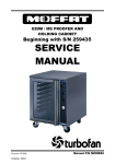
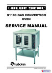
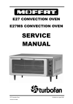
2.4 RATING PLATE LOCATION
The rating plate for G50 ranges is located to
the left of the control panel.
Rating plate
Figure 2.1
Revision 3/F3601
-9-
3. OPERATION
NOTE: A full user’s operation manual is supplied with the product and can be used for further
referencing of installation, operation and service.
3.1 OPERATION
3.1.1 HOB OPEN BURNERS
3.1.3 OVEN
Flame Failure Protection is incorporated by
way of a thermo-electric system for each
burner which will shut off the gas supply to
that burner in the event that the burner goes
out, so that raw gas is not expelled.
1) Open oven doors. Push in thermostat
knob and rotate anti-clockwise to the
PILOT ( ) position.
2) Hold in the thermostat knob.
3) With the thermostat knob held in, light the
pilot burner by pressing the piezo button.
View the lit pilot burner through the
inspection hole.
1) Select the burner, depress and turn the
corresponding knob anti-clockwise to full
position ( ).
2) With control knob depressed, light burner.
3) Release knob approximately
seconds after lighting burner.
4) Release knob approximately 10 seconds
after lighting pilot.
10-20
5) Pilot should now remain alight - if not,
repeat steps 2 to 4.
4) Burner should stay alight - if not, repeat
Steps 2-3.
6) The oven temperature can now be set by
rotating the control knob anticlockwise to
any position from the 1 - 7 markings. The
control knob requires to be slightly
depressed when starting from the pilot
position, however once out of the pilot
position it can be freely turned up or
down.
5) The burner can now be operated. At this
position it is full ( ).
6) To achieve simmer control, depress knob
and rotate fully anti-clockwise. Or operate
between full ( ) and low ( ) positions.
7) When main burner is not required, turn
knob clockwise back to the off position.
See the temperature conversion chart
below for oven centre temperatures
obtained at the gas mark settings 1 - 7.
3.1.2 GRIDDLES
1) Depress the control knob and rotate anticlockwise to the pilot ( ) position.
Gas Mark
Temp °C
2) With the control knob depressed, press
the piezo button to ignite the pilot burner.
Repeat until lit.
3) Release knob approximately 10 seconds
after lighting pilot.
4) Pilot should now remain alight - if not,
repeat steps 2 to 4.
5) Full flame can now be achieved by
rotating control anti-clockwise to the first
stop ( ).
6) Low flame can be achieved by depressing
the control knob and rotating fully anticlockwise ( ).
Revision 3/F3601
-10-
1
2
3
4
5
6
7
100 130 160 190 225 260 290
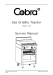
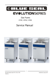
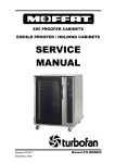
Inside the body of the gas valve is an
electromagnet connected to a spring loaded
plunger. When the electromagnet is
energized, it holds the plunger in, allowing gas
to flow through the valve.
When the
electromagnet
is
de-energized, the plunger snaps to the closed
3.2 EXPLANATION OF CONTROL
SYSTEM
SAFETY SYSTEM
The purpose of the safety system is to shut off
the flow of gas if the flame goes out. It is
comprised
of
the flame
itself, the
thermocouple, and the flame failure gas valve.
Thermocouple
The burner flame is lit by holding in the gas
control knob, which in turn temporarily pushes
the plunger inside the safety valve open and
allows gas to flow through. Once the burner
is lit, the thermocouple will begin to generate
millivolts (after about 10 to 30 seconds of
being heated) and will energize the
electromagnet inside the gas valve. Once
energized the electromagnet holds the
plunger inside the gas valve in the open
position. The plunger has to have been
pushed all the way in for the electromagnet to
be able to hold it in place. If the burner flame
goes out for some reason, the thermocouple
will cool after about 10 to 30 seconds and
stop generating millivolts. The electromagnet
will then de-energize, and the plunger will
snap shut, cutting off the flow of gas.
Electromagnet
Plunger
Gas flow
Shaft
Knob
Gas flow
Detail of each component in the safety system
is explained below.
Plunger
Figure 3.2
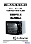
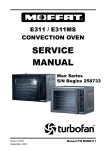
THERMOCOUPLE
position, stopping the flow of gas.
The thermocouple is a device that generates
electricity when heat is applied to the tip.
Millivolts are provided to the electromagnet by
the thermocouple (not shown) which
generates millivolts when heated.
The
thermocouple screws into a fitting at the back
of the gas valve to make an electric
connection. By pressing in the gas control
knob, the plunger can be temporarily held
open while lighting. There's two reasons for
this; gas has to flow through the safety valve
to make it possible to light the burner, and
secondly the plunger has to be pushed all the
way in for the electromagnet to hold it in. I.e.;
the electromagnet is strong enough to hold
the plunger in once there, but is not strong
enough to pull it in by itself. Sometimes a
problem with the flame not staying lit after
releasing the button can be attributed to not
pushing the plunger all the way in.
Insulator
Nut
Internal
Wire
Conductor
Tip
Figure 3.1
The tip of the thermocouple is located in the
burner flame, and the nut at the other end of
the thermocouple screws into the back of the
gas valve. Inside the copper tubing is a wire
which is joined at the tip but insulated from the
rest of the tubing. These two parts (the
copper tubing and wire) make up the "wiring"
for an electrical circuit. When these two
dissimilar metals, wire and tip, are heated an
electrical voltage is produced. This type of
thermocouple generates between 7 and 30
millivolts when heated in the pilot flame.
The Troubleshooting Guide (Section 5) should
be used to identify any incorrect operation.
On correct identification of the operating fault
the Troubleshooting Guide will make
reference to the corrective action required, or
refer to the Fault Diagnosis section and/or
ELECTROMAGNETIC FLAME FAILURE
GAS VALVE
The purpose of the safety valve is to shut off
the flow of gas if the pilot flame goes out.
Revision 3/F3601
-11-
4. MAINTENANCE
4.1 CLEANING
4.2 ROUTINE PROCEDURES
EXTERIOR
It is recommended that a service check is
conducted every six months.
Clean with detergent. Baked on deposits or
discoloration may require a good quality
stainless steel cleaner or stainless steel wool.
Always apply cleaner when the unit is cold
and rub in the direction of the grain.
1) Visual check of the pilot and main burners,
to see if correct size flame, and colour on
main burner.
2) Check the gas pressure with a manometer
(water gauge).
INTERIOR
3) Check and clean inside control area,
making sure that all connections are
secure.
Do not use wire brushes, steel wool or other
abrasive materials. Clean the oven regularly
with a good quality domestic oven cleaner.
Once a week, remove and clean built up
grease etc. from the oven racks and bottom
spill over cover.
4) Check condition of the gas supply pipe,
regulator and fittings.
5) Check for gas leaks at all fittings inside
and outside the unit.
6) Check gas control operation, smooth to
operate.
Regrease gas controls if
required (refer service section).
MAINTENANCE
To achieve the best results cleaning must be
regular and thorough, and all controls and
mechanical parts checked and adjusted
periodically by a competent serviceman. If
any small faults occur, have them attended to
promptly. Don't wait until they cause a
complete breakdown. It is recommended that
a service check is conducted every 6 months.
7) Check thermocouple operation, burner
should hold quickly after lighting, replace
thermocouple if required.
8) Adjust the door ball catches. Check the
striker plates for wear.
NOTE: The gas supply must be OFF during
cleaning or maintenance.
Revision 3/F3601
-12-
5. TROUBLE SHOOTING
WARNING: ALL INSTALLATION AND SERVICE REPAIR WORK MUST BE CARRIED
OUT BY QUALIFIED PERSONS ONLY.
5.1 HOB
Open Burners
FAULT
MAIN BURNERS WILL NOT
LIGHT
MAIN BURNER GOES OUT
WHEN KNOB RELEASED
NO LOW FIRE
MAIN BURNER FLAME
INCORRECT COLOUR
(YELLOW / WAVY)
Revision 3/F3601
POSSIBLE CAUSE
REMEDY
Wrong size or blocked injectors. Replace / clean injectors.
(Refer service section 6.3.2)
Obstruction in burner.
Clean burner.
Incorrect supply pressure.
Check supply pressure.
Faulty gas control.
Replace gas control.
(Refer service section 6.3.4)
Releasing knob before the
thermocouple is heated.
Hold control in for longer (30 s),
see if pilot will stay lit.
Thermocouple faulty.
(Refer fault diagnosis 6.1.1)
Replace thermocouple.
(Refer service section 6.3.3)
Gas magnet faulty.
(Refer fault diagnosis 6.1.1)
Replace gas magnet.
(Refer service section 6.3.13)
Incorrect supply pressure.
Check supply pressure.
Low fire adjustment incorrect.
Adjust.
(Refer service section 6.4.3)
Aeration setting incorrect.
Adjust aeration.
(Refer service section 6.4.1)
-13-
Griddle Burners
FAULT
PILOT BURNER WILL NOT
LIGHT
POSSIBLE CAUSE
REMEDY
No gas supply.
Ensure gas supply is connected
and on (bottles not empty).
Gas pressure too low.
Check gas supply pressure.
(Refer specifications section)
Blocked pilot injector.
Clean or replace pilot injector.
(Refer service section 6.3.8)
Knob on gas control won’t go
fully in.
Remove obstruction / correct
control panel mounting.
Replace gas control.
(Refer service section 6.3.12)
PILOT FLAME SMALL / LAZY
/ YELLOW
PILOT GOES OUT WHEN
KNOB RELEASED
Gas pressure too low.
Check gas supply pressure.
(Refer specifications section)
Blocked pilot injector.
Clean or replace pilot injector.
(Refer service section 6.3.8)
Releasing knob before the
thermocouple is heated.
Hold control in for longer (30 s),
see if pilot will stay lit.
Pilot flame too small.
Correct fault.
(Refer fault:Pilot Flame Small)
Thermocouple faulty.
(Refer fault diagnosis 6.1.2)
Replace thermocouple.
(Refer service section 6.3.9)
Gas magnet faulty.
(Refer fault diagnosis 6.1.2)
Replace gas magnet.
(Refer service section 6.3.13)
GRIDDLE BURNER WILL NOT Wrong size or blocked injectors. Replace / clean injector.
LIGHT
(Refer service section 6.3.6)
PILOT GOES OUT WHEN
MAIN BURNER COMES ON
PIEZO IGNITOR NOT
SPARKING
NO LOW FIRE
Revision 3/F3601
Obstruction in burner.
Clean burner.
Incorrect supply pressure.
Check supply pressure.
Faulty gas control.
Replace gas control.
(Refer service section 6.3.12)
Incorrect gas pressure.
Check supply / adjust pressure.
(Refer specifications section)
Faulty gas control.
Replace gas control.
(Refer service section 6.3.12)
Short in high tension lead.
(Refer fault diagnosis 6.1.3)
Replace lead.
(Refer service section 6.3.11)
Piezo faulty.
(Refer fault diagnosis 6.1.3)
Replace piezo.
(Refer service section 6.3.10)
Incorrect supply pressure.
Check supply pressure.
Low fire adjustment incorrect.
Adjust.
(Refer service section 6.4.3)
-14-
5.2 OVEN
FAULT
PIEZO IGNITOR NOT
SPARKING
PILOT WON’T LIGHT
POSSIBLE CAUSE
REMEDY
Short in high tension lead.
(Refer fault diagnosis 6.1.3)
Replace lead.
(Refer service section 6.4.1)
Piezo faulty.
(Refer fault diagnosis 6.1.3)
Replace piezo.
(Refer service section 6.4.2)
Knob on gas control won’t go
fully in.
Remove obstruction. Correct
control / wrapper mounting.
Replace gas control.
(Refer service section 6.4.4)
PILOT FLAME SMALL
PILOT GOES OUT WHEN
KNOB RELEASED
No gas supply.
Ensure gas is connected and
on (bottles not empty).
Gas pressure too low.
Check gas supply pressure.
(Refer specifications section)
Blocked pilot spud.
Clean or replace pilot spud.
Refer service section 6.4.6)
Gas pressure too low.
Check gas supply pressure.
(Refer specifications section)
Pilot adjustment screw out of
adjustment.
Adjust pilot adjustment screw.
(Refer service section 6.5.6)
Pilot spud restricted.
Clean pilot spud.
(Refer service section 6.4.8)
Releasing knob before the
thermocouple heated.
Hold control in for longer (30 s),
see if pilot will stay lit.
Pilot flame too small.
Correct fault.
(Refer fault:Pilot Flame Small)
PILOT FLAME YELLOW /
LAZY
PILOT GOES OUT WHEN
MAIN BURNER COMES ON
Thermocouple faulty.
(Refer fault diagnosis 6.1.2)
Replace thermocouple.
(Refer service section 6.4.9)
Gas pressure incorrect.
Check gas supply pressure.
(Refer specifications section)
Restriction in pilot spud or
aeration.
Clean or replace as required.
(Refer service section 6.4.8)
Incorrect gas pressure.
Check supply / adjust pressure.
(Refer specifications section)
Faulty gas control.
Replace gas control.
(Refer service section 6.4.4)
PILOT GOES OUT WHILE
Gas supply - incorrect or
OVEN IN USE, CAN RE-LIGHT fluctuating pressure.
Revision 3/F3601
Check supply / adjust pressure.
Thermocouple faulty.
(Refer fault diagnosis 6.1.2)
Replace thermocouple.
(Refer service section 6.4.9)
Draught at installation (blowing
pilot out).
Shield oven from excessive
breeze.
-15-
FAULT
MAIN BURNERS WILL NOT
LIGHT
POSSIBLE CAUSE
REMEDY
Wrong size or blocked injectors. Replace / clean injectors.
(Refer service section 6.4.6)
Small pilot flame.
Correct fault.
(Refer fault:Small Pilot Flame)
Faulty gas control.
Replace gas control.
(Refer service section 6.4.4)
Incorrect supply pressure.
Check supply correct pressure.
BURNERS DO NOT BURN
Incorrect supply pressure.
CORRECTLY (ROAR /LIGHT
BACK /INCORRECT COLOUR) Burner aeration incorrect.
Check supply pressure.
Adjust burner aeration slide.
(Refer service section 6.5.1)
Incorrect injector sizes.
Check injector sizes and
replace if necessary.
(Refer service section 6.4.6)
Burner faulty.
Replace burner.
(Refer service section 6.4.5)
Gas supply fluctuating.
Check supply correct pressure.
Gas control faulty.
Replace gas control.
(Refer service section 6.4.4)
Thermostat out of calibration.
Recalibrate thermostat.
(Refer service section 6.5.7)
OVEN TOO HOT
Thermostat out of calibration.
Recalibrate thermostat.
(Refer service section 6.5.7
DOOR DOES NOT CLOSE
Tray in way of door.
Correctly position tray in rack.
Door catch setting incorrect.
Adjust.
(Refer service section 6.5.9)
Door hinges / pins worn.
Replace.
(Refer service section 6.4.10)
SET TEMPERATURE NOT
REACHED
Revision 3/F3601
-16-
6. SERVICE PROCEDURES
WARNING: ALL INSTALLATION AND SERVICE REPAIR WORK MUST BE CARRIED
OUT BY QUALIFIED PERSONS ONLY.
SECTION
6.1
FAULT DIAGNOSIS .............................................................................................................19
6.1.1
6.1.2
6.1.3
6.2
Hob Control Panel ...............................................................................................20
Oven Control Panel .............................................................................................20
Oven Burner ........................................................................................................20
Right Hand Side Panel ........................................................................................20
REPLACEMENT - HOB........................................................................................................21
6.3.1
6.3.2
6.3.3
6.3.4
6.3.5
6.3.6
6.3.7
6.3.8
6.3.9
6.3.10
6.3.11
6.3.12
6.3.13
6.4
Hob Burner Goes Out When Knob Released......................................................19
Pilot Goes Out When Control Knob Released.....................................................19
Piezo Ignitor Not Sparking...................................................................................19
ACCESS ...............................................................................................................................20
6.2.1
6.2.2
6.2.3
6.2.4
6.3
PAGE NO.
Open Burner ........................................................................................................21
Open Burner Injector ...........................................................................................21
Open Burner Thermocouple ................................................................................21
Open Burner Gas Control....................................................................................21
Griddle Burner .....................................................................................................22
Griddle Burner Injector ........................................................................................22
Griddle Burner Pilot .............................................................................................22
Griddle Burner Pilot Injector ................................................................................22
Griddle Burner Pilot Thermocouple .....................................................................23
Griddle Burner Piezo Ignitor ................................................................................23
Griddle Burner H.T. Lead ....................................................................................23
Griddle Burner Gas Control .................................................................................23
Gas Magnet .........................................................................................................24
REPLACEMENT - OVEN......................................................................................................24
6.4.1
6.4.2
6.4.3
6.4.4
6.4.5
6.4.6
6.4.7
6.4.8
6.4.9
6.4.10
6.4.11
Oven H.T. Lead ...................................................................................................24
Oven Piezo Electrode..........................................................................................24
Oven Piezo Ignitor ...............................................................................................24
Oven Gas Control................................................................................................25
Oven Burner ........................................................................................................25
Oven Burner Injector ...........................................................................................25
Oven Pilot Burner ................................................................................................26
Oven Pilot Burner Injector ...................................................................................26
Oven Thermocouple ............................................................................................26
Door Hinge ..........................................................................................................27
Door Catch ..........................................................................................................27
WARNING: ALWAYS CHECK/TEST FOR GAS LEAKS AFTER SERVICE REPAIRS ON
THE GAS SYSTEM.
Revision 3/F3601
-17-
6.5
ADJUSTMENT / CALIBRATION ..........................................................................................27
6.5.1
6.5.2
6.5.3
6.5.4
6.5.5
6.5.6
6.5.7
6.5.8
6.5.9
Revision 3/F3601
Burner Aeration ...................................................................................................27
Re-greasing Gas Control.....................................................................................27
Hob Low Fire Adjustment ....................................................................................28
Oven High Fire Adjustment .................................................................................28
Oven Low Fire Adjustment ..................................................................................28
Oven Pilot Adjustment .........................................................................................29
Thermostat Calibration ........................................................................................29
Door Ball Catch Setting .......................................................................................30
Door Alignment....................................................................................................30
-18-
top 5mm of the thermocouple tip.
6.1 FAULT DIAGNOSIS
NOTE: The thermocouple should not touch
the burner.
6.1.1 HOB BURNER GOES OUT WHEN
KNOB RELEASED
Check thermocouple connection to gas
control is firm (loose connections will cause
resistance in millivolt circuit and result in pilot
outage).
Thermocouple faulty
Inspect thermocouple for build-up of carbon or
food deposits on the tip. Clean off any
deposits, taking care not to scratch off the
aluminium coating on the thermocouple.
If connection is OK, then disconnect the
thermocouple from the gas control, light the
pilot, and whilst holding the control knob in,
measure voltage between the thermocouple
and earth (e.g. the body of the gas control).
This should read approximately 30mV. If this
reading is less than 10mV then the
thermocouple is faulty—replace.
Check that the thermocouple tip is in the
flame zone of the burner. When the burner is
lit, the flame should impinge on the top 5mm
of the thermocouple tip.
NOTE: The thermocouple should not touch
the burner.
Gas magnet faulty
Check thermocouple connection to gas
control is firm (loose connections will cause
resistance in millivolt circuit and result in flame
outage).
If thermocouple milli-voltage is above 10mV,
and the pilot still will not hold, then the gas
magnet is faulty - replace.
If connection is OK, then disconnect the
thermocouple from the gas control, light the
burner, and whilst holding the control knob in,
measure voltage between the thermocouple
and earth (e.g. the body of the gas control).
This should read approximately 30mV. If this
reading is less than 10mV then the
thermocouple is faulty—replace.
6.1.3 PIEZO IGNITOR NOT SPARKING
Short in high tension lead
If repeated sparking of the piezo shows
intermittent sparking at the electrode, then the
lead should be traced to find area of short.
This can normally be visually seen as the
spark arcs. If the lead is shorting the best
solution is to replace it, as the electrical
insulation strength of the lead may have
deteriorated.
Gas magnet faulty
If thermocouple milli-voltage is above 10mV,
and the burner still will not hold, then the gas
magnet is faulty - replace.
If the spark arc can be seen at the electrode
insulator at the pilot burner instead of at the
electrode tip, then the insulator probably has a
fracture and should be replaced.
6.1.2 PILOT GOES OUT WHEN CONTROL
KNOB IS RELEASED
Pilot flame too small
Piezo ignitor faulty
If pilot can be lit but the flame is too small to
impinge on the thermocouple, then check the
gas pressure. If ok, remove pilot injector from
pilot burner and check for blockages and/or
correct size.
If no spark at all can be generated, remove
piezo ignitor and hold close to the hob body,
depress piezo ignitor and if a spark cannot be
generated to hob body the piezo ignitor is
faulty and should be replaced.
NOTE: If piezo ignition fails, the pilot can be
manually lit in the interim until the piezo circuit
is repaired.
A standard taper torch or
matches/lighter can be used for manual
back-up ignition.
Thermocouple faulty
Inspect thermocouple for build-up of carbon or
food deposits on the tip. Clean off any
deposits, taking care not to scratch off the
aluminium coating on the thermocouple.
Check that the thermocouple tip is in the
flame zone of the pilot burner. When the
burner is lit, the flame should impinge on the
Revision 3/F3601
-19-
6.2 ACCESS
6.2.4 RH SIDE PANEL
6.2.1 HOB CONTROL PANEL
1) Remove two screws at rear of oven.
1) Remove all gas control knobs by pulling
away from the control panel.
2) Remove the two screws securing the
control panel to the hob.
3) Remove the control panel.
Figure 6.2.4
Two screws
2) Slide RH side panel towards rear of oven
and remove.
Figure 6.2.1
6.2.2 OVEN CONTROL PANEL
1) Remove the one screw at the top centre of
the control panel.
2) The control panel will now hinge along
bottom edge.
One screw
Figure 6.2.5
Figure 6.2.2
6.2.3 OVEN BURNER
1) Open oven doors.
2) Remove all racks and trays from inside
oven.
3) Remove enamelled tray from bottom of
oven.
4) Remove flame baffle from oven (one
screw).
One screw
Figure 6.2.3
Revision 3/F3601
-20-
4) Unscrew the thermocouple from the gas
control.
6.3 REPLACEMENT - HOB
6.3.1 OPEN BURNER
1) Remove pot-stand/trivet and pot-stand
spider from above burner to be replaced.
2) Remove burner cap.
Thermocouple
3) Lift the burner out of the unit, and replace.
6.3.2 OPEN BURNER INJECTOR
Figure 6.3.4
1) Remove main open burner (refer 6.3.1).
5) Replace and reassemble in reverse order.
2) Remove heat shield (refer figure 6.3.2).
3) Unscrew injector from gas control.
IMPORTANT:
WHEN SCREWING
THERMOCOUPLE BACK INTO GAS
CONTROL,
ONCE
THREADED
UP,
TIGHTEN UP ANOTHER ¼ TURN ONLY.
DO NOT OVER TIGHTEN.
Injector
6.3.4 OPEN BURNER GAS CONTROL
1) Remove fat collection trays.
Figure 6.3.1
2) Remove control panel (refer 6.2.1)
4) Clean or replace injector as necessary,
and re-assemble in reverse order.
3) Remove open burner (refer 6.3.1).
4) Disconnect thermocouple from the gas
control.
6.3.3 OPEN BURNER THERMOCOUPLE
1) Remove burner (refer 6.3.1).
2) Remove heat shield (2 screws).
Thermocouple
Two screws
Figure 6.3.5
5) Using 19 mm spanner, undo compression
nut securing gas control to manifold
assembly.
Figure 6.3.2
3) Unscrew the thermocouple
thermocouple bracket.
from
the
Compression
nut
Figure 6.3.6
Thermocouple
6) Replace and re-assemble in reverse
order. Check for gas leaks with soapy
water.
Figure 6.3.3
Revision 3/F3601
-21-
6.3.5 GRIDDLE BURNER
6.3.7 GRIDDLE BURNER PILOT
1) Remove griddle plate.
1) Remove griddle burner (refer 6.3.5).
3
2) Unscrew the /16" screw at rear of burner.
2) Remove heat shield (refer figure 6.3.6).
3) Unscrew the pilot supply tube, piezo
electrode, and thermocouple from pilot
assembly.
3
/16" Screw
Pilot
supply
tube
Figure 6.3.7
Figure 6.3.10
3) Remove burner, replace and reassemble
in reverse order.
4) Undo two screws securing pilot burner
bracket to griddle reflector.
6.3.6 GRIDDLE BURNER INJECTOR
1) Remove griddle burner (refer 6.3.5).
2) Remove the heat shield (two tabs).
Two screws
Figure 6.3.11
5) Remove pilot burner from bracket (two
screws).
Two tabs
6) Replace and reassemble in reverse order.
6.3.8 GRIDDLE BURNER PILOT INJECTOR
Heat shield
Figure 6.3.8
1) Remove griddle burner (refer 6.3.5).
2) Remove heat shield (refer figure 6.3.6).
3) Remove the griddle injector from the gas
control.
3) Unscrew the pilot supply tube from the
pilot burner assembly.
Griddle
injector
Pilot
supply
tube
Figure 6.3.9
4) Clean or replace as necessary, and
reassemble in reverse order.
Figure 6.3.12
4) Extract injector from pilot burner.
5) Clean or replace as necessary, and
reassemble in reverse order.
Revision 3/F3601
-22-
6.3.9 GRIDDLE BURNER PILOT
THERMOCOUPLE
1) Remove griddle burner (refer 6.3.5).
2) Remove heat shield (refer figure 6.3.6).
3) Unscrew the pilot thermocouple from the
pilot burner assembly.
Piezo
nut
Figure 6.3.13
3) Remove H.T. lead from piezo ignitor.
4) Replace and reassemble in reverse order.
Pilot
thermocouple
6.3.11 GRIDDLE BURNER H.T. LEAD
Figure 6.3.13
1) Remove control panel (refer 6.2.1).
2) Remove H.T. lead from piezo ignitor and
pilot electrode.
4) Undo thermocouple from griddle gas
control.
Thermocouple
Pilot
electrode
Figure 6.3.14
5) Replace and reassemble in reverse order.
Figure 6.3.14
IMPORTANT:
WHEN SCREWING
THERMOCOUPLE BACK INTO GAS
CONTROL,
ONCE
THREADED
UP,
TIGHTEN UP ANOTHER ¼ TURN ONLY.
DO NOT OVER TIGHTEN.
3) Replace lead and reassemble in reverse
order.
6.3.12 GRIDDLE BURNER GAS CONTROL
1) Remove fat collection trays.
6.3.10 GRIDDLE BURNER PIEZO IGNITOR
2) Remove griddle plate.
1) Remove control panel (refer 6.2.1).
3) Remove control panel (refer 6.2.1).
2) Undo nut securing piezo ignitor from rear
of control panel.
4) Disconnect piezo H.T. lead from piezo
ignitor.
5) Unclip and remove front heat shield (refer
figure 6.3.6).
6) Slide reflector panel forward and lift away
at rear.
7) Undo pilot supply and disconnect pilot
thermocouple from gas control.
Revision 3/F3601
-23-
8) Using 19 mm spanner, undo compression
nut securing gas control to manifold
assembly.
6.4 REPLACEMENT- OVEN
6.4.1 OVEN H.T. LEAD
Pilot supply
1) Open oven control panel (refer 6.2.2).
2) Gain access to the oven burner (refer
6.2.3).
Compression
nut
3) Remove the piezo H.T. lead from the
ignitor and the piezo electrode, and then
remove lead from oven.
Figure 6.3.15
9) Replace and reassemble in reverse order.
Check for gas leaks with soapy water.
H.T. Lead
6.3.13 GAS MAGNET
Figure 6.4.1
1) Remove the gas control from the hob
(refer 6.3.4 / 6.3.12).
4) Replace H.T. lead, and re-assemble in
reverse order.
2) On suitable work surface, remove rear nut
from gas control.
6.4.2 OVEN PIEZO ELECTRODE
1) Gain access to the oven burner (refer
6.2.3).
Rear nut
2) Remove the H.T. lead from the piezo
electrode.
Figure 6.3.16
3) Extract gas magnet.
3) Undo the nut securing the piezo electrode
to the pilot assembly, and remove
electrode.
4) Replace and reassemble in reverse order.
4) Replace and reassemble in reverse order.
Gas control
Magnet
Rear nut
Figure 6.3.17
Electrode nut
Figure 6.4.2
6.4.3 OVEN PIEZO IGNITOR
1) Open oven control panel (refer 6.2.2).
2) Undo nut securing piezo ignitor to control
panel.
Revision 3/F3601
-24-
Ignitor nut
Three screws
Figure 6.4.6
5) Remove gas control from control cavity.
Figure 6.4.3
6) Replace and reassemble in reverse order.
3) Replace ignitor and reassemble in reverse
order.
7) Set valve up according to sections 6.5.46.5.6.
8) Check oven for correct operation.
6.4.4 OVEN GAS CONTROL
6.4.5 OVEN BURNER
1) Open oven control panel (refer 6.2.2) and
remove RH side panel (refer 6.2.4).
1) Gain access to oven burner (refer 6.2.3).
2) Remove all gas pipes and thermocouple
from the gas control.
2) Remove the two screws securing the
burner to the oven bottom.
Pilot supply
Thermocouple
Burner supply
Two screws
Main gas supply
Figure 6.4.4
Figure 6.4.7
3) Remove thermostat phial from bracket
inside oven, and pass phial through wall of
oven.
3) Replace the burner and reassemble in
reverse order.
6.4.6 OVEN BURNER INJECTOR
Thermostat
phial
1) Remove the oven burner (refer 6.3.21).
2) Unscrew the burner injector.
Figure 6.4.5
Burner
injector
4) Undo three screws (and nuts) securing
gas control to bracket.
Figure 6.4.8
3) Clean or replace as necessary, and
reassemble in reverse order.
Revision 3/F3601
-25-
6.4.7 OVEN PILOT BURNER
6.4.9 OVEN THERMOCOUPLE
1) Gain access to the oven burner (refer
6.2.3).
1) Gain access to the oven burner (refer
6.2.3).
2) Disconnect the pilot supply tube,
thermocouple and piezo H.T. lead from
the pilot burner.
2) Undo the thermocouple from the pilot
burner.
Thermocouple
Thermocouple
H.T. lead
Pilot supply
Figure 6.4.12
3) Remove right hand side panel (refer
6.2.4).
Figure 6.4.9
3) Undo the two screws securing the pilot
burner bracket to the bottom of the oven.
4) Undo thermocouple from rear of gas
control.
Thermocouple
Two
screws
Figure 6.4.13
Figure 6.4.10
5) Withdraw thermocouple from oven.
4) Undo the two screws securing the pilot
burner to the bracket.
6) Replace and reassemble in reverse order.
5) Replace the pilot burner and reassemble
in reverse order.
IMPORTANT:
WHEN SCREWING
THERMOCOUPLE BACK INTO GAS
CONTROL,
ONCE
THREADED
UP,
TIGHTEN UP ANOTHER ¼ TURN ONLY.
DO NOT OVER TIGHTEN.
6.4.8 OVEN PILOT BURNER INJECTOR
1) Gain access to the oven burner (refer
6.2.3).
2) Remove the pilot supply tube from the
pilot burner.
Pilot supply
Figure 6.4.11
3) Extract the pilot injector from the burner,
and clean or replace as required.
Revision 3/F3601
-26-
6.5 ADJUSTMENT
6.4.10 DOOR HINGE
1) Open oven door.
6.5.1 BURNER AERATION
2) Undo three screws securing hinge to oven
body, and three screws securing hinge to
door.
The open top, griddle and oven burners can
all be adjusted to give the most efficient flame.
If the flame is yellow and wavy, then the
burner needs adjusting.
1) Loosen the aeration slide screw.
Door
hinge
Aeration slide screw
(Open burners)
Figure 6.4.14
3) Replace hinge and reassemble in reverse
order.
Figure 6.5.1
6.4.11 DOOR BALL CATCH
Aeration slide screw
(Oven burner)
1) Open right hand oven door.
2) Loosen the door catch locknut.
3) Turn the slot on the ball catch
anticlockwise to unscrew the ball catch.
4) Replace and reassemble.
Figure 6.5.2
Ball
catch
2) Adjust the aeration slide as required.
The most efficient flame is clear blue/
green in colour.
Figure 6.4.15
6.5.2 RE-GREASING HOB GAS CONTROL
1) Remove gas control (refer 6.3.4).
2) Remove two screws securing shaft of gas
control.
Two
Screws
Figure 6.5.3
3) Withdraw spindle from gas control barrel,
noting it’s orientation.
Revision 3/F3601
-27-
Burner pressure
test point
Spindle
Figure 6.5.4
4) Apply a suitable high temperature gas
cock grease or lubricant such as ROCOL A.S.P (Anti scuffing paste) / Dry Moly
Paste to the outside of the spindle.
5) Replace spindle and re-assemble gas
control in reverse order.
Figure 6.5.6
4) If the pressure is incorrect, then adjust the
maximum flow rate adjuster screw,
located on underside of gas control.
6.5.3 HOB LOW FIRE ADJUSTMENT
1) Remove control panel (refer 6.2.1).
NOTE: Do not unscrew more than two turns.
2) Light burner and turn gas tap to low
position.
3) Turn low fire adjustment screw, located
above and to the right of the gas control
shaft, until the desired low flame is
achieved.
NOTE: The low fire adjustment screw should
be paint sealed following adjustment.
Maximum flow
adjustment screw
Low fire
adjustment
screw
Figure 6.5.7
5) Paint seal the adjustment screw.
6.5.5 OVEN LOW FIRE ADJUSTMENT
Figure 6.5.5
NOTE: The minimum flow setting is important
to ensure good temperature control of the
oven. The minimum flow setting on the oven
control is factory set and sealed. It should not
be necessary to adjust at any stage. However,
if correct operation is required to be verified,
the following check should be made.
6.5.4 OVEN HIGH FIRE ADJUSTMENT
NOTE: The maximum flow setting on the
oven control is factory set on the oven control
is factory set and sealed. It should not be
necessary to adjust at any stage. However, if
correct operation is required to be verified, the
following check should be made.
1) Remove the RH side panel (refer 6.2.4),
and the oven control panel (refer 6.2.2).
2) Light the oven burner (refer operation
section).
1) Remove the RH side panel (refer 6.2.4),
and the oven control panel (refer 6.2.2).
3) Fit a manometer over the burner
pressure test point (front test point) on the
gas control. Turn the control to gas mark
7, then turn back until just before the
thermostat control snap-action turns the
burner off. The burner should now be
operating at the minimum flow rate. The
burner pressure at this rate should be as
listed below.
2) Light the oven burner (refer operation
section).
3) Check the oven burner pressure by fitting
a manometer over the burner pressure
test point (front test point) on the gas
control. The burner pressure should be as
listed below with burner at maximum rate
(gas mark 7).
Propane 35 mbar ± 2.0 (14” WG ±0.4”)
Propane 7.5 mbar (3” WG)
Natural
Natural
8.7 mbar ± 1.0 (3.5” WG ±0.2”)
Revision 3/F3601
-28-
3.7 mbar (1.5” WG)
6.5.7 OVEN THERMOSTAT CALIBRATION
NOTE: As the thermostat control has special
fasteners, a Torx T20 security tip or
screwdriver is required. These are readily
available from a tool retailer.
Burner pressure
test point
1) Place an accurate thermometer or
thermocouple in the centre of the oven.
2) Light burner and set the thermostat knob
to gas mark 4.
Figure 6.5.8
3) Wait for the oven temperature to stabilise
(approximately 20 minutes). Oven centre
temperature should be 190°C ± 10°C.
4) If the pressure is incorrect, then adjust the
minimum flow rate adjuster screw, located
at the left hand bottom corner at the front
of the gas control.
Gas Mark
Temp °C
1
2
3
4
5
6
7
100 130 160 190 225 260 290
NOTE: Should a problem exist, the following
checks should be made before assuming
the thermostatic control calibration is
faulty.
Minimum flow
adjustment screw
a. Check burner pressure.
b. Check the MAXIMUM flow adjustment
setting on control valve (refer 6.5.4).
c. Check the MINIMUM flow adjustment
setting on control valve (refer 6.5.5).
Figure 6.5.9
d. Check the pilot burner rate adjustment
(refer 6.5.6).
5) Paint seal the adjustment screw.
4) Remove the cap (A) by prying off with a
small flat blade tip screwdriver.
6.5.6 OVEN PILOT ADJUSTMENT
5) With the control knob (C) in the off position
and while holding it in, undo the Torx head
screw (B).
NOTE: The pilot flame adjusting screw
should always be fully open and is factory
set and sealed in this position.
6) Pull the control knob (C) straight off taking
care not to rotate it at all while extracting.
Ensure the spring (D) is not lost.
1) Remove control panel (refer 6.2.1).
2) Light pilot burner.
7) Put a mark on the gear (E) for future
reference to rotation of gear.
3) To increase the pilot flame, turn pilot
adjustment screw anti-clockwise.
8) Carefully rotate
adjustment.
To decrease the pilot flame turn pilot
adjustment screw clockwise.
gear
(E)
for
One tooth rotation equals a temperature
change of 5ºC.
NOTE: The correct setting is achieved by
fully screwing in the adjustment screw,
and then unscrewing three full turns.
Anticlockwise to decrease temperature.
9) Replace the knob, ensuring spring is in
position and taking care not to rotate the
knob while inserting, hold fully in.
Pilot
adjustment
screw
Figure 6.5.10
Revision 3/F3601
the
-29-
10) Replace Torx head screw and release
knob.
6.5.9 DOOR ALIGNMENT
11) Test oven temperature, and re-adjust if
required.
A small amount of adjustment can be made to
the alignment of the oven doors in order to
ensure a good seal.
12) Push snap cap back into position on knob.
1) Open the oven doors, and loosen the
screws securing the door hinges to the
oven.
2) Adjust the door position a small amount to
ensure even sealing around the perimeter
of the door. As a guide, a single sheet of
paper should be able to be inserted
between the metal to metal seal.
E
D
C
B
3) Tighten the screws, and recheck the door
position.
A
Figure 6.5.11
6.5.8 DOOR BALL CATCH SETTING
1) Open right hand oven door.
2) Loosen the door catch locknut.
3) Turn the slot on the ball catch to adjust the
height of the roller, anticlockwise to
increase height, clockwise to decrease
roller height.
4) Tighten locknut.
Ball
catch
Figure 6.5.12
5) The position of the door catch plate can
also be adjusted in or out to ensure that
the door closes correctly.
Ball
catch
Figure 6.5.13
Revision 3/F3601
-30-
7. SPARE PARTS
PART NO
DESCRIPTION
Open Burners
004573
004574
004618
037190
037110
019430
019428
019429
019371
Burner Front
Burner Rear
Burner Cap
Injector (Natural) Ø 1.90 mm
Injector (Propane) Ø 1.10 mm
Gas Control
Thermocouple - Front M9 x 320 mm UNIFIED
Thermocouple - Rear M9 x 850 mm UNIFIED
Pressure Test Point
Griddle
014105
034210
034120
017800
019215K
018693
018692
019428
020119
018095
016385
016386
016387
Burner
Injector (Natural) Ø 2.10mm
Injector (Propane) Ø 1.20mm
Gas Control
Pilot Burner Kit
Pilot Orifice (Natural) Ø 0.32 mm
Pilot Orifice (Propane) Ø 0.20 mm
Thermocouple
Piezo Ignitor
Piezo H.T Lead
Griddle 300mm
Griddle 600mm
Griddle 900mm
Oven
012248
018691K
020253
032280
032150
018693
018692
019406K
016320
018695
020267
Oven Burner
Oven Pilot Burner Kit
Oven Thermocouple
Oven Burner Injector (Natural) Ø 2.80 mm
Oven Burner Injector (Propane) Ø 1.50 mm
Pilot Orifice (Natural) Ø 0.32 mm
Pilot Orifice (Propane) Ø 0.20 mm
Thermostat/Gas Control Kit
Piezo Ignitor
Piezo H.T Lead
Low fire screw - (Natural and Propane) 1.2mm
General
004125
016659
004158
019435
019436
011853
011005
010254
018031
018081K
019455
Revision 3/F3601
Pot Stand/Trivet
Pot Stand Spider
Hob Spillage Tray
Knob - Open Burner (FRONT & GRIDDLE)
Knob - Open Burner (REAR)
Regulator 3/4" - (Natural Gas only)
Ball Catch
Striker Plate
Handle Tube
Handle End Cap
Instruction Book
-31-
8. PARTS DIAGRAM
8.1
MAIN ASSEMBLY
G50C ILLUSTATED
Revision 3/F3601
-32-
Pos
Part no.
Description
1
2
016511
016387
016386
016385
019424
014105
019431
014106
012862
012863
012849
012850
016659
004125
004618
004079
004080
019261
012856
012858
022064
004158
------------------004611
004610
004609
004608
004626
004627
004628
004629
020119
018095
019435
019436
015045
015046
015047
012017
019260
019259
015042
004257
004258
014157
014798
014804
014925
013249
004338
010254
004157
014927
013661
015139
TROUGH TRAY
GRIDDLE ('A' OPTION)
GRIDDLE ('B' OPTION)
GRIDDLE ('C' OPTION)
HEAT SHIELD
GRIDDLE BURNER
GRIDDLE REFLECTOR
GRIDDLE BURNER BRACKET
SPLASHBACK - G50
SPLASHBACK - G50-8
HOB BACK PANEL - G50
HOB BACK PANEL - G50-8
POT STAND SPIDER
POT STAND
BURNER CAP
FRONT BURNER ASSEMBLY
REAR BURNER ASSEMBLY
POT SUPPORT
HOB - G50
HOB - G50-8
HEAT SHIELD
HOB TRAY
INSULATION
GAS PIPING ASSEMBLY (SEE SECTION 8.2)
HOB CONTROL PANEL G50-A
HOB CONTROL PANEL G50-B
HOB CONTROL PANEL G50-C
HOB CONTROL PANEL G50-D
HOB CONTROL PANEL G50-8A
HOB CONTROL PANEL G50-8B
HOB CONTROL PANEL G50-8C
HOB CONTROL PANEL G50-8D
PIEZO IGNITOR
H.T LEAD (NOT ILLUSTRATED)
KNOB ASSEMBLY FRONT
KNOB ASSEMBLY REAR
SIDE PANEL - R.H G50
SIDE PANEL - R.H G50-8
COVER PANEL G50-8
BASE PANEL G50-8
CONTROL BRACKET - RH
CONTROL BRACKET - LH
SIDE INSULATION PANEL
CHASSIS G50
CHASSIS G50-8
SPACER FOOT
GAS HOUSING
BACK PANEL
SECOND BACK PANEL G50-8 ONLY
SIDE PANEL - LH
STRIKER PLATE EXTENSION
STRIKER PLATE
DRAUGHT BOX
BOTTOM INSULATION PANEL
LEG TUBE - CASTOR
CASTOR ASSEMBLY (34 & 35 ASSEMBLED)
3
4
5
6
7
8
9
10
11
12
13
14
15
16
17
18
19
20
21
22
23
24
25
26
27
28
29
30
31
32
33
34
35
Revision 3/F3601
-33-
36
37
38
39
40
41
42
43
44
45
46
47
48
49
50
51
52
53
54
55
56
57
58
59
60
012776
015652
011046
014854
014873
014872
010990
012233
004259
013247
004612
004156
011186
010377
014314
014356
014355
013248
016406
004334
004333
018138
011005
018789
018081K
018131
013243
013244
024023
Revision 3/F3601
CASTOR ASSEMBLY
CASTOR YOKE
WHEEL - 75mm
WHEEL PIN
LEG TUBE - ADJUSTABLE
ADJUSTABLE LEG ASSEMBLY (37 & 38 ASSEMBLED)
ADJUSTABLE FOOT
VENT
OVEN
SPACER PANEL
OVEN CONTROL PANEL
OVEN TRAY
FLAME BAFFLE
OVEN RACK
OVEN TRIM - TOP
OVEN TRIM - R.H
OVEN TRIM - L.H
HINGE PLATE
BUTT HINGE
DOOR INNER - R.H
DOOR INNER - L.H
HANDLE STIFFENER
BALL & LOCKNUT
BALL CATCH PLATE
HANDLE END CAP
DOOR HANDLE
DOOR OUTER - R.H
DOOR OUTER - L.H
RADIATION PANEL
-34-
9.2.2 GAS PIPING ASSEMBLY (UK only)
8.2
G50C ILLUSTRATED
1
2
8
9
3
5
6
4
17
51
18
13
12
19
14
20
15 16
21
10
22
23
27
24
11
28
29
26
25
30
32
31 23 24
34
26
33
}
35
36
37
38
39
44
43 45
38
40
49
47
46
41
42
48
50
OVEN PILOT DETAIL - VIEWED FROM REAR
G50-UK
GAS PIPING ASSEMBLY
G50C ILLUSTRATED
Revision 3/F3601
-35-
Pos
Part no.
Description
1
2
3
4
5
6
014803
011833
013473
011853
012048
013837
011003
011002
011827
004695
004696
004697
004698
004699
004700
004701
004702
019371
019425
019215K
018692
HOB SUPPLY PIPE
TEE - 3/4"
NIPPLE - 3/4" HEX
REGULATOR (NATURAL GAS ONLY)
REDUCING BUSH - 3/8" x 3/4"
CONNECTOR (FROM S/N 224660)
CONNECTOR - 1/2" x 3/8" (TO S/N 224659) – NOT ILLUSTRATED
CONE NUT (TO S/N 224659) – NOT ILLUSTRATED
MACK UNION - 3/4"
MANIFOLD G50 A
MANIFOLD G50 B
MANIFOLD G50 C
MANIFOLD G50 D
MANIFOLD G50-8 A
MANIFOLD G50-8 B
MANIFOLD G50-8 C
MANIFOLD G50-8 D
PRESSURE TEST POINT
GRIDDLE PILOT BRACKET
GRIDDLE PILOT BURNER KIT (INCLUDES ITEMS 13,14,16,17,18)
PILOT INJECTOR Ø0.20mm - PROPANE GAS
(INCLUDED AS PART OF ITEM 12)
PILOT INJECTOR Ø0.32mm - NATURAL GAS
(INCLUDED AS PART OF ITEM 12)
PILOT ELECTRODE (INCLUDED AS PART OF ITEM 12)
THERMOCOUPLE - GRIDDLE
ELECTRODE NUT (INCLUDED AS PART OF ITEM 12)
OLIVE (INCLUDED AS PART OF ITEM 12)
COMPRESSION NUT 1/4" (INCLUDED AS PART OF ITEM 12)
GRIDDLE PILOT SUPPLY TUBE
COMPRESSION NUT
OLIVE
GRIDDLE INJECTOR Ø1.20mm - PROPANE GAS
GRIDDLE INJECTOR Ø2.10mm - NATURAL GAS
BACKNUT - 1/8" (UP TO S/N 246144)
ELBOW - 1/8" x 1/4" (ASSEMBLED AS PART OF ITEM 25)
GAS CONTROL - GRIDDLE
SPIGOT NUT
OLIVE (NOT ILLUSTRATED)
THERMOCOUPLE BRACKET - REAR
TARGET CLAMP NUT (NOT ILLUSTRATED)
THERMOCOUPLE - REAR
THERMOCOUPLE BRACKET - FRONT
TARGET CLAMP NUT (NOT ILLUSTRATED)
THERMOCOUPLE - FRONT
OPEN BURNER INJECTOR Ø1.10mm - PROPANE GAS
OPEN BURNER INJECTOR Ø1.90mm - NATURAL GAS
GAS CONTROL - OPEN BURNERS
CONTROL SUPPLY PIPE
GAS CONTROL KIT - OVEN THERMOSTAT
LOW FIRE SCREW - LPG 0.95mm
LOW FIRE SCREW - NAT 1.50mm
CONNECTOR - 3/8" x 1/2"
1
/4" NUT & OLIVE
PILOT TUBE
THERMOCOUPLE - OVEN
OVEN SUPPLY PIPE
8
9
10
11
12
13
018693
14
15
16
17
18
19
20
21
22
23
24
25
26
27
28
29
30
31
32
33
34
35
36
37
38
39
018744
019428
018742
018739
018740
019262
017805
017806
034120
034210
011740
019335
017800
017804
017803
019413
018741
019429
019412
018741
019428
037110
037190
019430
019255
019406K
022407
022408
013837
018097
019258
020253
019256
Revision 3/F3601
-36-
40
41
42
43
44
032150
032230
012254
011310
018691K
019217
018693
45
46
47
48
49
50
51
018741
019407
018742
018744
018740
018739
019330
023863
Revision 3/F3601
OVEN INJECTOR Ø1.50mm - PROPANE GAS
OVEN INJECTOR Ø2.30mm - NATURAL GAS
INJECTOR SUPPORT BRACKET
OVEN BURNER
OVEN PILOT BURNER KIT (INCLUDES ITEMS 44,45,47,48,49)
OVEN PILOT INJECTOR Ø0.23mm - PROPANE GAS
(INCLUDED AS PART OF ITEM 43)
OVEN PILOT INJECTOR Ø0.32mm - NATURAL GAS
(INCLUDED AS PART OF ITEM 43)
CLAMP NUT (INCLUDED AS PART OF ITEM 43)
H.T LEAD - OVEN
ELECTRODE NUT (INCLUDED AS PART OF ITEM 43)
PILOT ELECTRODE (INCLUDED AS PART OF ITEM 43)
COMPRESSION NUT (INCLUDED AS PART OF ITEM 43)
OLIVE (NOT ILLUSTRATED)(INCLUDED AS PART OF ITEM 43)
OVEN PILOT BRACKET
GRIDDLE PILOT DRAFT BAFFLE (FROM S/N 215176)
-37-
9. SERVICE CONTACTS
AUSTRALIA
VICTORIA - MOFFAT PTY
HEAD OFFICE AND MAIN WAREHOUSE
740 Springvale Road
Mulgrave VIC 3170
Spare Parts Department
NEW SOUTH WALES - MOFFAT PTY
Unit 8/142 James Ruse Drive
Rosehill NSW 2142
Spare Parts
Tel (03) 9518 3888
Fax (03) 9518 3838
Free Call 1800 337 963
Fax (03) 9518 3895
Free Call 1800 337 963
Fax (03) 9518 3895
QUEENSLAND - MOFFAT PTY
30 Prosperity Place
Geebung QLD 4034
Spare Parts
Free Call 1800 337 963
Fax (03) 9518 3895
SOUTH AUSTRALIA - MOFFAT PTY
28 Greenhill Rd
Wayville SA 5034
Spare Parts
Tel (08) 8274 2116
Free Call 1800 337 963
WESTERN AUSTRALIA - MOFFAT PTY
PO Box 689
Joondalup Business Centre WA 6027
Spare Parts
Tel (08) 9305 8855
Free Call 1800 337 963
NATIONAL COVERAGE FOR 24 HOUR SERVICE OR MAINTENANCE DIAL
FREE CALL 1800 622 216 (AUSTRALIA ONLY)
CANADA
Lessard Agencies Limited
PO Box 97
Stn “D”
Toronto, ONT M6P 3J5
Tel (416) 766 2764
Fax (416) 760 0394
Free Call 1 888 537 7273
NEW ZEALAND
CHRISTCHURCH - MOFFAT LTD
16 Osborne St
PO Box 10-001
Christchurch
Spare Parts
Free Call 0800 Moffat
(0800 663 328)
Tel (03) 389 1007
Fax (03) 389 1276
AUCKLAND - MOFFAT LTD
4 Waipuna Road
Mt Wellington
Auckland
Spare Parts
Revision 3/F3601
Tel (09) 574 3150
Fax (09) 574 3159
Free Call 0800 Moffat
(0800 663 328)
-38-
UNITED KINGDOM
BLUESEAL LTD
Units 6-7 Mount St
Business Park
Birmingham B7 5QU
England
Tel 0121-327 5575
Fax 0121-327 9711
UNITED STATES OF AMERICA
MOFFAT INC.
3765 Champion Blvd
Winston-Salem
NC27115
Tel 1-800-551 8795
Fax 336 661 9546
NATIONAL COVERAGE FOR SERVICE OR MAINTENANCE DIAL
FREE CALL 1800 551 8795 (USA ONLY)
Revision 3/F3601
-39-