1
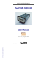
SeaSTAR 3100LRS USER MANUAL SeaSTAR 3100LRS User Manual Issue 1.0, August 2002 FSPAS Ref.: B31005102PMBRA0 Issue 1.0 08/02 FSPAS Ref.: B31005102PMBRA0 SeaSTAR 3100LRS USER MANUAL This page left intentionally blank FSPAS Ref.: B31005102PMBRA0 Issue 1.0 08/02 FSPAS Ref.: B31005102PMBRA0 SeaSTAR 3100LRS USER MANUAL Notice to Customers This manual has been produced to ensure the very best performance from your Fugro SeaSTAR receiver. The manual has been clearly set out with simple instructions to ensure trouble free usage of your Fugro SeaSTAR receiver. This publication could contain technical inaccuracies or typographical errors. Changes are periodically made to the information herein; these changes will be incorporated in new editions of the manual. Should you require further assistance please contact your local dealer or the Fugro SeaSTAR Perth office. Fugro SeaSTAR Customer Support and 24 Hour Help Line Fugro SeaSTAR Hoffsveien 31 C 0213 OSLO NORWAY Contact Numbers Office: Network Control Centre (NCC): +47 21 50 14 00 (24 hours) +61 8 9321 0284 (24 hours) Fax Numbers Office: Network Control Centre: +47 21 50 14 01 +61 8 9321 0885 World Wide Web Internet Address: Email address: www.fugroseastar.no [email protected] i FSPAS Ref.: B31005102PMBRA0 Issue 1.0 08/02 SeaSTAR 3100LRS USER MANUAL Dealer Information Name _____________________________ Address _____________________________ City _____________________________ State _____________________________ Post Code _____________________________ Country _____________________________ Phone _____________________________ Fax _____________________________ Email _____________________________ ii FSPAS Ref.: B31005102PMBRA0 Issue 1.0 08/02 SeaSTAR 3100LRS USER MANUAL One-Year Limited Hardware Warranty Fugro SeaSTAR and its operating companies world-wide, warrants this product to be free from defects in workmanship and material for a period of one year from the date of original sale by Fugro SeaSTAR or its authorised dealers, to the original purchaser or end user. Fugro SeaSTAR reserves the right to repair and/or replace, at its option, any part or parts found to be defective, provided such defects, in their opinion, are due to faulty material or workmanship and are not caused by unauthorised or improper repair or abuse, or normal wear. Purchaser shall be responsible for shipping and insurance of the returned product for repair under this warranty. Fugro SeaSTAR will pay shipping and insurance for the product's return to purchaser provided that the product returned proves to be defective under this limited warranty. This warranty applies only to normal usage of the product. It does not apply to units or electronic circuit boards defective due to improper installation or handling. Physical damage due to lightning or other electrical discharge and units subjected to fresh or salt-water contamination are not covered. Fugro SeaSTAR reserves the right not to warrant the product if, upon request, sufficient proof of recommended installation compliance as laid out in this manual is not provided. No other warranties are expressed or implied. No other warranties exist. Fugro SeaSTAR assumes no responsibility for any consequential or incidental losses or damages of any nature with respect to the use of this product. Issue 1.0 REVISION HISTORY August 2002 First Issue Manual Reference: SeaSTAR 3100LRS User Manual Copyright Fugro SeaSTAR 2002. No part of this manual can be reproduced without the express permission of Fugro SeaSTAR. iii FSPAS Ref.: B31005102PMBRA0 Issue 1.0 08/02 SeaSTAR 3100LRS USER MANUAL This page left intentionally blank iv FSPAS Ref.: B31005102PMBRA0 Issue 1.0 08/02 SeaSTAR 3100LRS USER MANUAL TABLE OF CONTENTS INTRODUCTION.............................................................................................. 1 ABOUT THIS MANUAL ......................................................................................1 SYSTEM FEATURES .........................................................................................1 3100LRS GETTING STARTED ....................................................................... 2 INITIAL SETUP .................................................................................................2 MODES OF OPERATION SETUP................................................................... 5 MODEL 3100LRS / RTCM MODE SETUP .........................................................5 MODEL 3100LRS / VBS OR VRC MODE SETUP ..............................................6 MODEL 3100 HIGH PERFORMANCE MODE SETUP .............................................7 RECEIVER INTERFACES............................................................................... 8 POWER ...........................................................................................................8 ANTENNA ........................................................................................................9 DATA ..............................................................................................................9 COMMAND.......................................................................................................9 UTILITY .........................................................................................................10 AUXILIARY .....................................................................................................11 INSTALLATION ............................................................................................. 12 INSTALLATION CONSIDERATIONS ....................................................................12 ELECTRICAL GROUNDING REQUIREMENTS ......................................................12 COUNTER ELECTROMAGNETIC FORCE (CEMF) ..............................................13 CABLE INSTALLATION.....................................................................................14 ANTENNA LOCATION ......................................................................................15 TECHNICAL SPECIFICATIONS ................................................................... 16 MENUS AND DISPLAYS .............................................................................. 17 POWER ON MENUS .......................................................................................19 CURRENT READINGS MENUS .........................................................................20 USER SETTINGS MENUS ................................................................................21 ABOUT MENUS ..............................................................................................23 3100LRS VBS SERVICES MENU ...................................................................24 3100LRS VIRTUAL BASE STATION (VBS) CONTROL MENU ............................26 3100LRS VIRTUAL REFERENCE CELL (VRC) SERVICES MENU .......................27 3100LRS VIRTUAL REFERENCE CELL (VRC) CONTROLS MENU .....................27 3100LRS HIGH PERFORMANCE (HP) SERVICES MENU ..................................28 3100LRS HIGH PERFORMANCE (HP) CONTROL MENU ...................................29 MAINTENANCE MENU .....................................................................................30 RECEIVER SUBSCRIPTION STATUS MENU .......................................................31 REMOTE SITES MENU FOR DGPS SERVICE....................................................32 v FSPAS Ref.: B31005102PMBRA0 Issue 1.0 08/02 SeaSTAR 3100LRS USER MANUAL CHANNEL SELECTION MENU.......................................................................... 33 AUTOSCAN MENU ......................................................................................... 34 3100LRSFM MENU SUPPLEMENT ................................................................ 36 ACRONYMS USED IN THIS MANUAL ......................................................... 37 APPENDIX A.................................................................................................. 39 RECEIVER SERVICE PROCEDURE .................................................................. 39 APPENDIX B.................................................................................................. 41 USER NOTES ................................................................................................ 42 vi FSPAS Ref.: B31005102PMBRA0 Issue 1.0 08/02 SeaSTAR 3100LRS USER MANUAL Introduction About This Manual This manual has been produced to assist the typical user with the installation and operation of the 3100LRS DGPS Receiver. System Features The 3100LRS DGPS Receiver is a component part of the Fugro world-wide DGPS Service. The Fugro service is a full-time differential GPS (DGPS) broadcast system delivering corrections from an array of GPS reference stations located around the globe. Reference stations provide industry standard formatted corrections to Network Control Centres (NCC’s) at strategic geographic locations, where the corrections are decoded, checked, and repackaged in a highly efficient format for broadcast. The data is modulated onto a RF carrier that is then up-converted for transmission to an L-band communications satellite. The signals are received at the user's location by an antenna, demodulated by a receiver, and are made available, after selection of the desired individual reference site's data set, as corrections for use in a GPS, differential-capable, receiver. The 3000 series of receivers support the following Fugro SeaSTAR® services: 1. Virtual Reference Cell, where the data from multiple reference stations is used in processor software to produce enhanced corrections for an optimised reference Cell. The resulting corrections are restructured as RTCM SC-104 version 2 corrections for direct application to a user's receiver or an internal Receiver. 2. Virtual Base Station where the data from multiple reference stations is used in processor software to produce enhanced corrections for the user's location. The resulting corrections are restructured as RTCM SC-104 version 2 corrections for direct application to a user's receiver. 3. DGPS Services Stand alone differential GPS, where corrections from one selected site are extracted from the incoming data stream and are reformatted to an industry standard Format, RTCM SC-104. 4. Hi Performance Services, where …. 1 FSPAS Ref.: B31005102PMBRA0 Issue 1.0 08/02 SeaSTAR 3100LRS USER MANUAL 3100LRS GETTING STARTED The purpose of this section is to get you started with the 3100LRS as quickly as possible. The guide will address receiving the satellite data carrier, and then checking the functionality of the internal GPS engine if fitted. We would ask you to quickly review the menu section of this manual, the menus are navigated by the Arrow buttons on the front panel, changes to options are made with the Up/Down keys, and items are entered using the centre key. Generally when the receiver is supplied to you it will be configured for the mode and data link(s) you have subscribed to. In most cases to get up and running will be a case of connecting the appropriate cables and applying power to the system. Initial Setup Figure 1. Bare Rear View of SeaSTAR 3100LRS Steps 1 through 8 pertain to all model 3100 receivers, the steps from then on are grouped by Model/Operation Mode. 1. Refer to the following diagrams as you will need to assemble all the required items. • • • • • • • • • 3100LRS DGPS Receiver DGPS Antenna DGPS Antenna Cable GPS Antenna if supplied GPS Antenna cable if supplied Power Cable Data Port Cable Aux. Port Data Cable if supplied Power Supply 2 FSPAS Ref.: B31005102PMBRA0 Issue 1.0 08/02 SeaSTAR 3100LRS USER MANUAL 2. Connect the power cable to a suitable 10-22V (10 – 36V if DC to DC converter fitted) DC power supply being sure to check correct polarity. 3. Install the DGPS antenna where it has a clear view of the sky in the direction of the satellite, refer to the NCC in your region for an azimuth/elevation chart for the satellite service you have subscribed to. 4. If you have a 3100LR8 or 3100LR12 an internal GPS engine has been fitted so you need to install the GPS antenna where it has a clear 360º unobstructed view of the sky through an elevation of 10 through 90º. 5. Connect the DGPS antenna cable between the DGPS antenna and the 3100LRS (TNC connector on rear panel). 6. If you have a 3100LR8 or 3100LR12 connect the GPS antenna cable between the GPS antenna and the 3100LR8 or 12 (BNC connector on rear panel). When the internal splitter is used only one antenna is connected to the DGPS RF connector. The GPS receives via the internal splitter. 7. Turn on the 3100LRS and observe the LCD display it should go through a power up sequence. 8. It is now time to make the 3100LRS Receiver acquire the DGPS signal. This can be done in one of 3 ways: a) By selecting the service directly in the Channel Selection menu (See the Channel Selection menu section. b) By entering the Frequency and Symbol Rate directly in the Channel Selection menu (See the Channel Selection Menu) c) .By Enabling Autoscan and waiting until the receiver finds an active service (See the Autoscan Menu section). For options a & b the receiver will indicate that is starting and frequency searching by display INITIALISING, FREQ SEARCH, SWEEPING, SYNCHRONISING, SERVICE ID, on the top line of the display and finally RECV when it has locked to the signal, in addition a signal strength will be indicated by a bar graph display. Should the RECV indicator not be displayed after 30-50 seconds check through steps 1 through 6 above. For option c the receiver will indicate Autoscan starting after the Wait Lock period has elapsed by displaying Autoscan on the top line of the LCD display. Once it has found an appropriate signal the receiver should display the RECV indicator with the signal strength indicated by a bar graph display. 3 FSPAS Ref.: B31005102PMBRA0 Issue 1.0 08/02 SeaSTAR 3100LRS USER MANUAL This page left intentionally blank 4 FSPAS Ref.: B31005102PMBRA0 Issue 1.0 08/02 SeaSTAR 3100LRS USER MANUAL Modes of Operation Setup Set the receiver to the required mode (either RAW, RTCM, VRC, VBS or HP). Some modes may not be available depending upon the security setting. Generally the receiver will be set to the correct mode prior to delivery to you, and will not be changeable. Model 3100LRS / RTCM Mode Setup • If the 3100LRS is operating in RTCM mode the RTCM data will appear on the DATA port, this port will need to be set up to match the requirements of your GPS receiver RTCM IN port, use the User Settings - Data Port menu item to set these. • For RTCM mode select the Remote Sites menu, move to the All Sites OFF menu item and press the enter key. Using the right menu key select the Sites (i.e. reference station(s)) you wish to output, toggle it’s status to ON with the Up/Down keys and press the centre button. When using the 3100LRS with an external GPS receiver only one RTCM station should be selected. An RS-232C data tester can be used to test for data output, the TX data line should flash every 3-4 seconds. Inmarsat Dome Antenna DC Power Supply (Typically vehicle cigarette lighter or 12V DC sealed lead acid battery) 3100LRS Receiver Spot Antenna Power or Data Data, Command or Utility Port DGNSS GNSS Receiver or Nav System Coupler Inmarsat Terminal Laptop Computer (Configuration & Maintenance) Figure 2 3100LRS Operating in RTCM Mode 5 FSPAS Ref.: B31005102PMBRA0 Issue 1.0 08/02 SeaSTAR 3100LRS USER MANUAL Model 3100LRS / VBS or VRC Mode Setup In this mode a composite set of RTCM corrections is computed from the GPS network data sent over the link. The following information is required to compute these corrections; time (supplied via the link), GPS almanac data (supplied via the link), and receiver location either entered via the front panel or from an external GPS receiver interfaced via the AUX port. When the unit is first supplied, or not used for a long period of time, or moved a large distance between use it may take up to 40 minutes to start outputting RTCM corrections. • If the 3100LRS is operating in VBS/VRC mode the RTCM data will appear on the AUX port, this port will need to be set up to match the requirements of your GPS receiver RTCM IN/NMEA out port, use the User Settings Aux. Port menu item to set these. • For the VBS or VRC operation the 3100LR needs to be supplied with a position for the area of operation, this can be supplied automatically from an external GPS receiver or manually via the front panel using the VBS POS menu item. If using an external GPS input the GPS receiver must be set up to output either $xxGGA or $xxGLL NMEA format position telegrams in addition to any other required message types. The NMEA data is input via the AUX port, therefore the port parameters must match those set for the RTCM data output, see the set up details for this port above. • The NMEA data input via the AUX port echoed to the DATA port for connection to user equipment, the data port can be set up independently of the AUX port using the User Settings - Data Port menu item. DC Power Supply (Typically vehicle cigarette lighter or 12V DC sealed lead acid battery) 3100LRS Receiver DGPS Antenna Power AUX Port Data, Command or Utility Port GPS Receiver DGPS Laptop Computer (Configuration & Maintenance) Figure 3 3100LRS operating in VBS or VRC Mode 6 FSPAS Ref.: B31005102PMBRA0 Issue 1.0 08/02 SeaSTAR 3100LRS USER MANUAL Model 3100 High Performance Mode Setup TEXT AND DIAGRAM TO BE ADDED AT A LATER DATE Figure 4 7 FSPAS Ref.: B31005102PMBRA0 Issue 1.0 08/02 SeaSTAR 3100LRS USER MANUAL Receiver Interfaces Power The 3100LRS will operate on any DC Voltage between 10V and 22V DC (10 – 36V if DC to DC converter fitted). When operational, the unit dissipates 7W of power. The 3100LRS can also withstand voltage surges up to 85V. The power input has reverse polarity protection. However, as the negative terminal is also attached to the housing ground, large currents can flow to any ground attachments made to the housing. Reverse polarity must therefore be avoided to prevent damage to the vehicle supply. At Voltages below 10V the unit will reset itself to prevent any data loss. At Voltages below 8.5V the receiver will turn itself off. Power is connected to the unit via a 2 metre long, black sheath, red & black 2core cable. The cable is terminated with a 3-pin Switchcraft EN3C3F female connector. The connector pin layout is illustrated in Figure 5. Pin 2 Pin 1 Pin 3 Figure 5 Pin layout of Switchcraft EN3C3F Female Connector The Switchcraft EN3C3F connector is terminated as follows : Pin 1 + DC voltage (red) Pin 2 – DC voltage (black) Pin 3 Not connected 8 FSPAS Ref.: B31005102PMBRA0 Issue 1.0 08/02 SeaSTAR 3100LRS USER MANUAL Antenna Antenna connection is made via a 5 metre RG58 low loss cable, which is terminated with a standard TNC 50-ohm male connector. If two antennae are supplied, each antenna will have its own cable. An antenna unit has an internal LNA (low noise amplifier) which is typically powered by 12V DC. When the 3100LRS is powered up, this voltage is present at the antenna socket on the rear panel. Therefore, care must be taken not to connect or disconnect an antenna when power is on. Data The Data port is a standard DB9 female socket. Data logging can be carried out by plugging a Psion data logger into this port. A laptop computer may also be plugged into the Data port for data logging and position information retrieval. Pin Number Signal 1 2 TXD2 3 RXD2 4 5 GND2 6 7 8 9 ANT STEERING* Table 1 Data Port Pin Assignment (* no connection by default) A special Data cable is supplied, terminated as shown in the Figure below. DB9 Male Pin number 2 3 5 2 metre cable ------------------------------------------- DB9 Female Pin number 2 3 5 Warning: Do NOT use standard RS232 cables. Command The Command port is a standard DB9 female socket. Receiver configuration (Fugro SeaSTAR 3000LCE board) can be carried out via this port by plugging in a laptop computer with ‘Toolkit’ software. 9 FSPAS Ref.: B31005102PMBRA0 Issue 1.0 08/02 SeaSTAR 3100LRS USER MANUAL The pin assignment for the Command port is shown in Table 2. Pin Number 1 2 3 4 5 6 7 8 9 Signal DCD TXD1 RXD1 DSR GND1 DTR CTS RTS Table 2 Command Port Pin Assignment Utility The Utility port is a standard DB9 female socket. The GPS engine can be configured via this port, using a laptop computer with proprietary software from the CD supplied. The pin assignment for the Utility port is shown in Table 3. Pin Number 1 2 3 4 5 6 7 8 9 Signal GPS CNTRL TXD Note: Can be RS232C or TTL GPS CNTRL RXD GPS CNTRL GND/GND4 TXD4/MON RXD4/MON Table 3 Utility Port Pin Assignment 10 FSPAS Ref.: B31005102PMBRA0 Issue 1.0 08/02 SeaSTAR 3100LRS USER MANUAL Auxiliary The Auxiliary port is a standard DB9 female socket. This port can be used to send enhanced RTCM (GPS correction) data to an external GPS receiver. However, it is necessary to first configure the Fugro SeaSTAR receiver board in the 3100LRS. This is carried out using a laptop computer with ‘Toolkit’ software via the Command port. Pin Number 1 2 3 4 5 6 7 8 9 Signal 1 DIAG* TXD3 RXD3 RESET* GND3 CAN L* CAN H* TEMPT MON* Q DIAG* Table 4 Auxiliary Port Pin Assignment ( * no connection by default) 11 FSPAS Ref.: B31005102PMBRA0 Issue 1.0 08/02 SeaSTAR 3100LRS USER MANUAL Installation Installation Considerations Before commencing installation of the 3100LRS in a vehicle or aircraft, the following should be considered : • Determine the preferred location for each unit. Consider cable length, connector attachment space (cable bend radius), stowing excess cable, moisture, chemical corrosion, vibration and heat exposure. • Before drilling holes, consider using existing hardware and locations where equipment was previously installed. Avoid drilling holes that may damage other equipment (e.g. structural frame members, electrical cables or fluid lines). • High vibration and high temperature locations should be avoided whenever possible. • In application where vibration exceeds 5Gs acceleration, shock mounts are required. (Refer to Customer support for mounting recommendations). • Vehicle primary power has voltages that may be harmful to personnel and equipment. Disconnect the battery cable from the battery –ve (negative) terminal before making connection to any power terminal within the vehicle. Electrical Grounding Requirements The 3100LRS requires a vehicle chassis connection that is a perfect ground. There should be a zero ohm reading between the receiver power socket –ve (negative) input and the point where the vehicle battery –ve (negative) terminal is connected to ground. 12 FSPAS Ref.: B31005102PMBRA0 Issue 1.0 08/02 SeaSTAR 3100LRS USER MANUAL Counter Electromagnetic Force (CEMF) A potential problem inherent in any installation of electronic systems within a vehicle is Counter Electro-magnetic Force (CEMF). CEMF is caused when relays or solenoids, connected to the vehicle DC power distribution, are de-energised. The voltage produced may exceed – 400 volts. CEMF is produced by equipment such as the following: • Electric fan brakes • Air conditioners • Starter relays • Electric pump relays CEMF is more than sufficient to damage or cause erratic operation of any electronic system that is also connected to the same vehicle DC power supply. CEMF can be eliminated by installing diodes at the relays and solenoids that cause the problem, and more importantly at the power supply cable connections on the receiver. A 47V, 5W, Zener diode (1N5368 or equivalent) should be connected between the receiver +ve (positive) power input terminal and ground, as illustrated in Figure 6. Battery +ve (positive) supply Ground Zener Diode Figure 6 Zener Diode Connected 13 FSPAS Ref.: B31005102PMBRA0 Issue 1.0 08/02 SeaSTAR 3100LRS USER MANUAL Cable Installation • Cables must be correctly installed for optimum system operation. Therefore, the following should be noted: • Do not route an L-Band receiver remote antenna cable with the cabling of any other radio system. This may cause interference between both systems. • If at all possible, do not run L-Band receiver antenna cables parallel to other radio system cabling closer than 30 centimetres. • If cables must cross, ensure that they cross at an angle of 90°. This minimises the possibility of interference. • As far as is practicable, ensure that cables and I/O connectors are unique and fit only in their allocated location. • Avoid routing cables along-side power generator cabling and other high electrical noise sources. This can cause interference. • Do not kink or force cables into sharp bends that may damage the cables and cause system failure. • After installation, ensure that excess cable in looped and clamped or tied safely away from any control cables, fuel lines, hydraulic lines or moving parts. When stowing over length cables, form loops not less than 150mm minimum cable bend radius. • Cable routing must (e.g. exhaust manifold). avoid high temperature exposure 14 FSPAS Ref.: B31005102PMBRA0 Issue 1.0 08/02 SeaSTAR 3100LRS USER MANUAL Antenna Location Antenna positioning is critical to system performance. The following conditions must be met for optimum system performance: • Antenna must be mounted at least 1.5 metres away from transmitting antennae of any frequency. Closer positioning may cause overloading of receiver RF circuits. • The antenna should be mounted at the highest practical point that will give a good view of the horizon and be as near level as possible. • The antenna must be located along the vehicle centre-line, or at a relevant reference point on the vehicle. 15 FSPAS Ref.: B31005102PMBRA0 Issue 1.0 08/02 SeaSTAR 3100LRS USER MANUAL Technical Specifications Receive Frequency Automatic Scanning: Environment Operating Temperature: Non-operating: Humidity: Vibration: Shock: Acceleration: Data inputs and outputs Four Serial Ports: Electrical Interference: Data Rates: 1525MHz to 1559MHz -20° to 65°C -40° to 85°C 95% non-condensing 3G/30 Hz/x, y & z axes Max 7G, 5-20m sec zero rebound 4G (with optional software) Message Rate: Plug Types: Command, Data, Auxiliary & Utility RS232-C 2400, 4800, 9600, 19200, 38400, 56700 1 – 5 Hz DB9 Connectors RF Input to Receiver: Power Connector: TNC female Switchcraft En3C3F Power Power Supply: Power Consumption: 10V DC to 22V DC (10V to 36V if DC to DC Converter fitted) 500mA at 12V DC Memory Program Memory: 2MB Physical Characteristics Dimensions (approx.): Weight (approx.): Display: Approvals Height 60mm Width 105mm Length 225mm 750 grams LCD Display TBA 16 FSPAS Ref.: B31005102PMBRA0 Issue 1.0 08/02 SeaSTAR 3100LRS USER MANUAL MENUS AND DISPLAYS Main Menu Structure After Power On Current Reading RECV → Current Reading ... User Settings RECV → User settings ... About RECV → About ... VBS Services (if Detector Mode = VBS) VBS Control VRC Services (if Detector Mode = VRS) RECV → VBS Services . . . RECV → VBS Controls……… RECV → VRC Services ……… VRC Controls RECV → VRC Control ……… HP Services (if Detector Mode – HP) HP Control RECV → HP Services ……… RECV → HP Control ……… 17 FSPAS Ref.: B31005102PMBRA0 Issue 1.0 08/02 SeaSTAR 3100LRS USER MANUAL Maintenance CDT RECV → Maintenance RECV → Ex 2001 Jun. 02 Remote Sites RECV → Remote Sites . . . Channel Selection Autoscan 3100LRSFM Menu Supplement (if FM selected) RECV → Channel Select ... RECV → Autoscan Contrl ... RECV → FM Mode : PRIMARY 18 FSPAS Ref.: B31005102PMBRA0 Issue 1.0 08/02 SeaSTAR 3100LRS USER MANUAL Power On Menus On power on the following sequence occurs: OmniSTAR LCE Ver. 02.11017 27Feb 01 Serial No Group No After initialisation, the receiver will start to search for the signal. The sequence continue after “Initialising”, and the receiver will attempt to acquire the frequency and if no signal is found the receiver will sweep for the satellite signal (“Sweeping”). Once a satellite signal is found “Synch” will appear when the receiver has acquired and synchronised with the signal and has commenced processing data. 386069 0001 CDT Left Day : 000 Hr : 03 VRC Synch If the receiver has found the frame, but it is the wrong service ID, this message will appear (This message sometimes appears briefly even if the settings are correct). Once locked-on, the strength of the received signal can be seen on the bar graph. Usually this will be 3-8 ½ bars. VRC Recv Note : If the mode doesn’t advance to “RECV”, first check that the signal frequency and symbol rate are set correctly for the uplink in use within the “Channel Selection” menu, and that the correct satellite is being tracked. 19 FSPAS Ref.: B31005102PMBRA0 Issue 1.0 08/02 SeaSTAR 3100LRS USER MANUAL Current Readings Menus Shows performance of the receiver section By pressing the ⇒ key the following sequence occurs. Pressing the ⇐ key gives the same fields in reverse. RECV → Current Reading ... Power shows the receive power in dB, this value is useful in determining the correct operation of the LNA. Power = Signal Quality shows a unit less hex value that indicates the signal quality. It is based on the I and Q values used in the signal tracking process. Actual Frequency shows actual operating frequency of the receiver, this will differ from the user selected Channel frequency. Service Identity is the P-MP service identifier, the number is in hex and is x2873 for Perth or US uplinks, and xC685 for the Eik, Norway AORE and IOR uplinks. Date & Time will start off from the firmware date until UTC time is received from the satellite after 20 min. RECV → -93 dBm RECV → Signal Qual = A Freq = 8 RECV → 1558511133 RECV → Service Id X2873 Apr02 RECV → 08:02 2001 If the ⇒ key is pressed again the Current readings menu option reappears. Pressing the ⇓ key moves onto the next menu. 20 FSPAS Ref.: B31005102PMBRA0 Issue 1.0 08/02 SeaSTAR 3100LRS USER MANUAL User Settings Menus Configures the data interfacing from the receiver to external equipment. By pressing the ⇒ key the following sequence occurs. Command Rate sets the baud rate for the command port used for inputting commands to the receiver from an external PC. Data Rate sets the baud rate for the data port used for output of DGPS correction data or enhanced position data. Auxiliary Rate sets the baud rate for the auxiliary port used for several different uses. Internal GPS Port Detector Mode controls how the receiver processes and the output format of the differential corrections received over the Starfix channel. The selections are HP/VRC/VBS,RTCM, RAW, PROM and OFF. RECV → User settings ... CMD RECV → 9600, 8, N, 1 DATA RECV → 9600,8,N,1 AUX RECV → 4800, 8, N, 1 RECV → IGPS 4800,8, N, 1 DemodMode VBS Contrast controls the intensity of the backlit display. RECV → Contrast RTCM OUT controls the termination of RTCM strings. Both these options should normally be left as Y for yes. Except for specific GPS units RTCM CR? 7 RECV → Y LF? Y 21 FSPAS Ref.: B31005102PMBRA0 Issue 1.0 08/02 SeaSTAR 3100LRS USER MANUAL Reacquisition Delay it is possible to set the delay used before the DSP reports a loss of lock on the satellite signal. This is done using the following command: Mtreacdelay = none <CR> Data Port selects the mode of output for the Data Port. If DETECTOR MODE is set to VBS then options for Data Port output are : SCF – Supercompressed Format ERTCM – Enhanced RTCM, Wide Area Corrections NMEA – Messages output from GPS Engine RECV → ReacDelay = SHORT Data Port RECV → ERTCM Note : If detector mode is set to “RAW” then output is in Supercompressed format (SCF). If set to “RTCM” then corrections for the selected station(s) will be in standard RTCM SC-104 format. If the ⇒ key is pressed again the User Settings menu option reappears. Pressing the ⇓ key moves onto the next menu. 22 FSPAS Ref.: B31005102PMBRA0 Issue 1.0 08/02 SeaSTAR 3100LRS USER MANUAL About Menus Repeats the firmware version and unit Serial Number as shown during the start-up sequence. By pressing the ⇒ key the following sequence occurs. Pressing the ⇐ key gives the same fields in reverse. RECV → About…….. Serial Number shows the receivers serial number. RECV → Serial No 386069 Group Number shows the receivers Group number. Group No = RECV → 0001 Main Software Version shows the Main Software version installed into the receiver and its issue date. 02.11.17 DSP Version shows the DSP (Digital Signal Processor) firmware version installed and its issue date RECV → DSP Ver 4.2 0598 RECV → 27Feb01 23 FSPAS Ref.: B31005102PMBRA0 Issue 1.0 08/02 SeaSTAR 3100LRS USER MANUAL 3100LRS VBS Services Menu Displays various data being input to the unit via the NMEA-0183 inputs from the internal or external GPS receiver. Some displays may show only zeroes if that particular NMEA option is not enabled on the receiver. Minimum requirement is for either the $GPGGA or $GPGLL sentences containing current position. These menus are only available if your receiver is connected to the VBS service. If the receiver is in VBS mode but there is no GPS unit attached (either internally or externally to the Auxiliary port) then this menu will display “No GPS / MANUAL Mode”. VBS Services by pressing the ⇒ key the following sequence occurs. Pressing the ⇐ key gives the same fields in reverse. Current Latitude shows latitude of the present position as read from the GPS receiver. This will be adequate for correct operation of the VBS whether or not the GPS receiver is in differential mode. Current Longitude shows longitude of the present position as read from the GPS receiver. This will be adequate for correct operation of the VBS whether or not the GPS receiver is in differential mode. GPS Time shows longitude of the present position as read from the GPS receiver. For some GPS engines this will be set to 00:00:00 until the receiver starts computing a position. Position Quality Information • 'Q' is the mode flag (0 = invalid; 1 = standard non-differential GPS; 2= DGPS) as reported by the $GPGGA NMEA telegram. • 'SVs' shows the number of satellites used for that particular position fix. (If Q=0, SVs will generally also be 0). 'HDOP' shows the quality of the fix geometry as a crude indicator of RECV → VBS Services . . . RECV → Lt : S 31 56’ 40.354 RECV → Ln : E 115 50’ 30.97” RECV → GPSTime : 08:33:56 RECV → Q : 1 SVs : 5HDOP : 1 Read from the $GPGGA sentence 24 FSPAS Ref.: B31005102PMBRA0 Issue 1.0 08/02 SeaSTAR 3100LRS USER MANUAL position quality. HDOP<3.0 is most reliable. DGPS correction information The first number shows Differential Correction age in seconds as measured by the GPS receiver; Stn is the station ID (always set to 100). List of satellite IDs shows the SVs used in the DGPS position fix as reported by the $GPGSA NMEA data telegram. RECV → Age : 99.0 Stn : 000 Read from the $GPGGA sentence RECV → SVs: 000000000000 Read from the $GPGSA sentence Receiver operating mode AQC shows either M for manual or A for Auto; POS shows 1, 2 or 3 D, where 1 is invalid, 2 is fixed height and 3 is a full 3-D position fix as reported by the $GPGSA NMEA data telegram. NMEA messages received flags for GGA, GLL, GSA and VTG sentences. Those not output will remain solid at 0. Satellite Messages received flags for the time, almanac and site reference messages. These will all say “Y” for Yes when each complete message has been received. AQC : A RECV → POS : 3D Read from the $GPGSA sentence RECV → GA : YLL : NSA : NTG : N RECV → Tm :Y Alm :Y Ste : Y Note : Display of correction age and station ID are not an indicator that the 3100LRS is outputting RTCM data. This display only shows data returned by the GPS receiver. Some models of receiver will not echo this information if not set in differential mode, despite receiving correction data. If the ⇒ key is pressed again the VBS Services menu option reappears. Pressing the ⇓ key moves onto the next menu. 25 FSPAS Ref.: B31005102PMBRA0 Issue 1.0 08/02 SeaSTAR 3100LRS USER MANUAL 3100LRS Virtual Base Station (VBS) Control Menu Allows setup of the internal VBS Processes primarily used when an external GPS receiver is used. VBS Controls (VBS extensions only) by pressing the ⇒ key the following sequence occurs. Pressing the ⇐ key gives the same fields in reverse. Input VBS Process Latitude Use the ⇑ and ⇓ keys to increase or decrease the number in each field to the correct value, also for N/S or E/W. Input VBS Process Longitude Use the ⇑ and ⇓ keys to increase or decrease the number in each field to the correct value, also for N/S or E/W. Confirm Entry Following input of lat and long, send the new entries into the VBS process by using the centre button on this menu item. Screen will then read “Input Accepted”. If a GPS is installed you will see : RECV → VBS Controls……… Lat : RECV → N 00 00’ 00.000” Lon : RECV → E 00 00’ 00.000” RECV → Set VBS Position RECV → GPS OK/AUTO Mode If the ⇒ key is pressed again the 3100LRS VBS Control menu option reappears. Pressing the ⇓ key moves onto the next menu. 26 FSPAS Ref.: B31005102PMBRA0 Issue 1.0 08/02 SeaSTAR 3100LRS USER MANUAL 3100LRS Virtual Reference Cell (VRC) Services Menu This menu is exactly the same as the VBS Services menu, except that the title is VRC Services. This menu only appears if detector mode is set to VRC. 3100LRS Virtual Reference Cell (VRC) Controls Menu Allows setup of the internal VRC processor primarily used when an external GPS receiver is used. VRC Controls (VRC Service only) by pressing the ⇒ key the following sequence occurs. Pressing the ⇐ key gives the same fields in reverse. RECV → VRC Control ……… Pressing either ⇒ or ⇐ again selects Either… cells #1 to #31 individually. Cells will RECV → display their actual ID’s (0-1-23), but Cell ID # 0001 ON only if they are enabled in the Cell Mask Only one cell will be shown as AUTO, or … the rest will be shown as OFF. The RECV → Receiver will automatically select the cell that is closest to the user’s current Cell ID # 0002 OFF location. If the ⇒ key is pressed until the VRC Controls menu appears then pressing the ⇓ key moves onto the next menu. 27 FSPAS Ref.: B31005102PMBRA0 Issue 1.0 08/02 SeaSTAR 3100LRS USER MANUAL 3100LRS High Performance (HP) Services Menu Displays various data being calculated by the internal High Performance 1 processor. Some displays may show only zeroes . HP Services by pressing the ⇒ key the following sequence occurs. Pressing the ⇐ key gives the same fields in reverse. RECV → HP Services …… Current Latitude shows latitude of the present position as calculated by the High Performance processor. RECV → LAT: S 31 56’ 40.584” Current Longitude shows longitude of the present position as calculated by the High Performance processor. RECV → LON: E 103 24’ 23.455” GPS Time shows the time of the last calculated position. Position Quality Information • 'Q' is the mode flag (0 = invalid; 1 = standard non-differential GPS; 2 = DGPS; 5 = HP) as reported by the HP processor. • 'SVs' shows the number of satellites used for that particular position fix. (If Q=0, SVs will generally also be 0). 'HDOP' shows the quality of the fix geometry as a crude indicator of position quality. HDOP<3.0 is most reliable. HP correction information The first number shows Differential Correction age in seconds as measured by the HP processor; Stn is the station ID (always set to 100). RECV → GPS Time: 10 :14 :58 RECV → Q : 2 SV’s : 6 HDOP : 1.6 RECV → DC-Age : 05.0 Stn : 0100 Read from the $GPGGA sentence If the ⇒ key is pressed again the HP Services menu option reappears. Pressing the ⇓ key moves onto the next menu. 1 During the initialisation period for the High Precision position calculation. 28 FSPAS Ref.: B31005102PMBRA0 Issue 1.0 08/02 SeaSTAR 3100LRS USER MANUAL 3100LRS High Performance (HP) Control Menu Allows setup of parameters used to control the High Performance calculation process. HP Controls (HP extensions only) by pressing the ⇒ key the following sequence occurs. Pressing the ⇐ key gives the same fields in reverse. RECV → HP Controls ….. Position Calculation Rate use the ⇑ and ⇓ keys to increase or decrease the rate at which position information is output by the 3100LRS RECV → Posn Rate : 5 Hz Position Format Selection use the ⇑ and ⇓ keys to cycle through the supported position output formats. RECV → Posn Format : NMEA If the ⇒ key is pressed again the 3000LR HP Control menu option reappears. Pressing the ⇓ key moves onto the next menu. 29 FSPAS Ref.: B31005102PMBRA0 Issue 1.0 08/02 SeaSTAR 3100LRS USER MANUAL Maintenance Menu Entries within this menu are of not generally of interest to the normal user, however, occasionally the user may be asked to report this data to the service provider in the event of problems therefore they are included for completeness. Maintenance Menu by pressing the ⇒ key the following sequence occurs. Pressing the ⇐ key gives the same fields in reverse. Security shows the Security Mask programmed into the receiver it is displayed as a 32bit hex number. The bit settings in this word determine the functionality of the receiver available to the user. Site Permission Mask it is displayed as 32 bit hex number. The Site Permission Mask determines what reference station data is available to the user when RTCM output is selected. RECV → Maintenance RECV → Securty = 00030DFD RECV → SPMask = XFFFFFFFE Would indicate all stations enabled. RECV → Set VBS Position RECV → Mask = 0xFFFFFFFE Bit Error Rate indicates current (2 min average) Bit Error Rate. RECV → BER Checksum Status shows the number of messages received since power On which have valid (OK) Checksum and the number Invalid (BAD). Subscription Mode This shows the user whether the receiver is in standard (STD) or USA (US) subscription mode. <1.0E-08 RECV → OK 491 BD 5 RECV → Subs Mode : STD 30 FSPAS Ref.: B31005102PMBRA0 Issue 1.0 08/02 SeaSTAR 3100LRS USER MANUAL SW Select selects the Version of software the Reciver will execute. Selecting a new Version of the software will restart the Receiver. CPU Usage shows current processor utilisation. Kernel Usage shows current Real Time Executive Utilisation. SW Sel RECV → 02.11.17 RECV → CPU Usage = 5% RECV → Kn1 Usage = 0% Receiver Subscription Status Menu Receiver Subscription Status Menus show the current receiver subscription status. The display will vary depending on the subscription mode. RECV → Ex 2001 Jun. 02 Indicates that the receiver will expire on XXX indicates what type of subscription the date displayed is currently in use (HP, VBS, VRC, RTCM, FMRTCM, 8VBS, 8VRC, 12VBS, EXPIRE RECV → 12VRC). This is displayed on every DEMOD EXPIRED menu item. Indicates that the expiry date has been exceed and the receiver has expired RECV → CDT 53 Days HH:MM:SS Indicates the subscription mode to be CDT and shows the time remaining. CDT-OR RECV → CDT-OVR 15:35:21 Indicates that the CDT subscription has over run, the timer will count up for a pre-determined grace period then stop. RECV → CDT EX DEMODULATOR EXPIRED Indicates that the receiver has exceeded the count down time and has expired. 31 FSPAS Ref.: B31005102PMBRA0 Issue 1.0 08/02 SeaSTAR 3100LRS USER MANUAL Remote Sites Menu for DGPS Service When using the VBS or HP service this menu does not apply. Use only if you want to output a single station into an external GPS receiver The menu allows the operator to select RTCM data output from a single reference station, or from a subset of the total number of stations transmitted on the Starfix channel, if using the receiver only. Remote Site Selection by pressing the ⇒ key the following sequence occurs. Pressing the ⇐ key gives the same fields in reverse. RECV → Remote Sites . . . Pressing the ⇒ key once after the menu prompt gives “Toggle all sites OFF” as the first choice. All sites RECV → OFF Pressing the ⇐ key once from the menu prompt gives “Toggle all sites ON” as the first choice. All sites RECV → ON Pressing either ⇒ or ⇐ again selects Either.. stations #1 to #31 individually. If Site RECV → Mapping messages are being ID ; # 00325 OFF transmitted stations will display their actual ID’s. Unused spaces in the Supercompressed format will show or... station ID’s between the end of the valid RECV → range and 31. Id : # 00325 ON If the ⇒ key is pressed again the Remote Sites menu option reappears. Pressing the ⇓ key moves onto the next menu. 32 FSPAS Ref.: B31005102PMBRA0 Issue 1.0 08/02 SeaSTAR 3100LRS USER MANUAL Channel Selection Menu By pressing the ⇒ key the following sequence occurs. Pressing the ⇐ key gives the same fields in reverse. Service Selection List Frequency and Symbol Rate can be selected automatically by selecting the name of the DGPS service from this list. The currently selected item can be changed by using the up and down arrows to scroll through the list. Pressing the centre button selects the currently displayed item as the service and automatically sets the frequency and symbol rate. RECV → Channel Select ... RECV → Perth Optus If a manual setting of the frequency and symbol rate is needed then simply adjust the frequency and symbol rate as described in the menu items below. When you next return to this menu, it will display “Custom - see FR / SR”. Frequency Frequency selection is set here for the P-MP channel in use, the frequency value is entered in Hertz. The entered value will be in the range 1525000000 to 1559000000 Hz. RECV → Freq = 1558510000 Change the entered frequency using the up and down arrows, then press centre button before moving on to the Symbol Rate - The display will briefly flash “INPUT ACCEPTED”, then “WAITING FOR REMOTE SITE DATA” because of clearing of site tables. Symbol Rate Symbol rate for the P-MP channel in use is entered here. The RECV → available options are 609, 1219, 2438, Symbol Rae = 2438 4876 which equate to user satellite data rates of 300, 600, 1200, and 2400 BPS respectively. If the ⇒ key is pressed again the Channel Selection menu option reappears. Pressing the ⇓ key moves onto the next menu. 33 FSPAS Ref.: B31005102PMBRA0 Issue 1.0 08/02 SeaSTAR 3100LRS USER MANUAL Autoscan Menu Autoscan is a special feature, which allows the 3100LRS Receiver’s to automatically search for another satellite signal to use. This feature only starts if it is enabled and if the receiver cannot lock the current satellite signal for the period specified in the Wait Lock menu (default is 60 seconds). The receiver has an internal table of possible services and attempts to lock onto the most appropriate service for the period specified in the Wait Scan menu. If it succeeds it continues to use this service. Otherwise another service is selected and the process is repeated until a successful service is found or the original service comes back on-line. During the autoscan process, the receiver’s menu displays “Autoscan …” on the top line and the service it is currently scanning on the bottom line. By pressing the ⇒ key the following sequence occurs. Pressing the ⇐ key gives the same fields in reverse. Autoscan enabled This menu item allows the autoscan feature to be selectively enabled and disabled. Change the Autoscan enabled state by pressing the up and down arrows, then press the centre button. The display will briefly flash “INPUT ACCEPTED”. Wait Lock This is the length of time the receiver must be without a DGPS signal before the Autoscan feature begins to search for a new satellite service. RECV → Autoscan Contrl ... RECV → AutoScan On? N RECV → Wait Lock = 00060sec Change the wait lock using the up and down arrows, then press centre button before moving on to the wait scan The display will briefly flash “INPUT ACCEPTED” 34 FSPAS Ref.: B31005102PMBRA0 Issue 1.0 08/02 SeaSTAR 3100LRS USER MANUAL Wait Scan This is the length of time the receiver will spend trying to lock into each signal that it knows about. RECV → Wait Scan = 00030sec Change the wait scan using the up and down arrows, then press centre button before moving on - The display will briefly flash “INPUT ACCEPTED” If the ⇒ key is pressed again the Autoscan Selection menu option reappears. Pressing the ⇓ key moves onto the next menu. NB. Changing services will reset the site tables in the receiver. The reference sites used in the VBS calculation are different between services. 35 FSPAS Ref.: B31005102PMBRA0 Issue 1.0 08/02 SeaSTAR 3100LRS USER MANUAL 3100LRSFM Menu Supplement This menu item is only available if your unit is configured as an FM receiver and is located in the User Settings menu. FM Mode sets the mode of operation for the FM extension. The options are OFF, SECONDARY, PRIMARY and FM ONLY. RECV → FM Mode : PRIMARY 36 FSPAS Ref.: B31005102PMBRA0 Issue 1.0 08/02 SeaSTAR 3100LRS USER MANUAL Acronyms Used In This Manual CEMF Counter Electro-magnetic Force DGPS Differential Global Positioning System GGA Global Positioning System fixed data (NMEA standard) GLL Geographic position (NMEA standard) GPS Global Positioning System GSA Global Positioning System, dilution of position, active satellite (NMEA standard) GSV GPS satellites in view (NMEA standard) LED Light Emitting Diode LNA Low Noise Amplifier NCC Network Control Centre NMEA National Marine Electronics Association (Standard for interfacing marine electronic devices) RF Radio Frequency RTCM Radio Technical Commission Maritime VTG ‘Track mode good’ and ‘ground speed’ (NMEA standard) ZDA Time and date (NMEA standard) 37 FSPAS Ref.: B31005102PMBRA0 Issue 1.0 08/02 SeaSTAR 3100LRS USER MANUAL This page left intentionally blank 38 FSPAS Ref.: B31005102PMBRA0 Issue 1.0 08/02 SeaSTAR 3100LRS USER MANUAL APPENDIX A Receiver Service Procedure If an Fugro SeaSTAR receiver unit fails to perform, contact the Network Control Centre (NCC) within the region, after following the procedural checks. We wish to hear about frequently experienced problems and your assistance will help by copying the form on the next page, filling in the details requested and faxing or mailing the form to the NCC for on-forwarding to Product Marketing. The most common problems are interfacing, and usually occur at installation time. If you have an interfacing connection not covered in this manual we would like to assist you and produce another technical bulletin that may assist other users in the future. If a problem appears that you think may be caused by a system performance problem, contact the NCC in your region for any system aberrations that may have been experienced. We are sensitive to our customers’ needs and we want to assure specified system performance at all times. There could, however, be situations where conditions are below par, such as fringe area operations, radio communication disturbance etc., and, as Fugro SeaSTAR receiver monitors the system performance continuously, these conditions would be noted. 39 FSPAS Ref.: B31005102PMBRA0 Issue 1.0 08/02 SeaSTAR 3100LRS USER MANUAL This page left intentionally blank 40 FSPAS Ref.: B31005102PMBRA0 Issue 1.0 08/02 SeaSTAR 3100LRS USER MANUAL APPENDIX B Fugro SeaSTAR Receiver Problem Report Form Please copy this form and report problem with as much detail as possible. Problem with: Signal Y/N Fugro SeaSTAR Y/N Date: Manual Y/N Receiver Y/N Description of problem: Person Reporting: Contact Phone #: Model #: Serial #: Customer Name: Customer Address: Customer Phone #: Date purchased: / GPS Receiver used: / Dealer: Serial #: Area of operations: Symptoms from display (if any): 41 FSPAS Ref.: B31005102PMBRA0 Issue 1.0 08/02 SeaSTAR 3100LRS USER MANUAL User Notes 42 FSPAS Ref.: B31005102PMBRA0 Issue 1.0 08/02