1
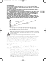
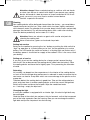
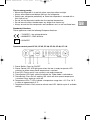
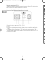
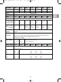
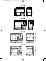
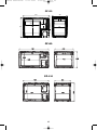
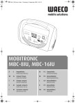
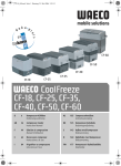
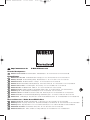
manual 4445100020
27.11.2002
http://www.waeco.de
9:57 Uhr
Seite 2
E-Mail: [email protected]
Zentrale/Headquarters
D
WAECO International GmbH · D-48282 Emsdetten · Hollefeldstraße 63 · Tel. +49-25 72/8 79-0 · Fax +49-25 72/8 79-300
Europa/Europe
DK
E
F
FIN
WAECO Handels-Ges. mbH · A-2483 Ebreichsdorf · Fischagasse 44 · Tel. +43-22 54/7 20 31-0 · Fax +43-22 54/7 20 31-9
WAECO (Schweiz) AG · CH-8153 Rümlang (Zürich) · Riedackerstrasse 7a · Tel. +41-1-8 18 71 71 · Fax +41-1-8 18 71 91
WAECO Danmark A/S · DK-6640 Lunderskov · Tværvej 2 · Tel. +45-75 58 59 66 · Fax +45-75 58 63 07
WAECO Ibérica SA · E-08340 Vilassar de Mar (Barcelona) · Torrent de Ca L’Amat, 85 · Tel. +34-93/7 50 22 77 · Fax +34-93/7 50 05 52
WAECO Int’l Division France · F-95740 Frépillon · 10 rue de Méry · Tel. +33-1 34 18 40 00 · Fax +33-1 34 18 40 10
WAECO Finland OY · FIN-00880 Helsinki · Pulttitie 17 · Tel. +3 58-42-45 92 200 · Fax +3 58-9-75 93 7 00
I
WAECO Italcold SRL · I-61015 Novafeltria · Zona Industriale Sartiano, 298/9 · Tel. +39-05 41/92 08 27 · Fax +39-05 41/92 02 37
N
WAECO Norge AS · N-3208 Sandefjord · Leif Weldingsvei 16 · Tel. +47-33 42 84 50 · Fax +47-33 42 84 59
NL
WAECO Benelux B.V. · NL-4700 BL Roosendaal · Postbus 1461 · Ettenseweg 60 · Tel. +31-1 65/58 67 00 · Fax +31-1 65/55 55 62
S
UK
WAECO Svenska AB · S-42131 Västra Frölunda (Göteborg) · Gustaf Melins gata 7 · Tel. +46-31/7 34 11 00 · Fax +46-31/7 34 11 01
WAECO UK Ltd. · UK-Broadmayne · Dorset DT2 8LY · Unit G1 · Roman Hill Business Park · Tel. +44-13 05/85 40 00 · Fax +44-13 05/85 42 88
Übersee/Overseas + Naher Osten/Middle East
AUS WAECO Pacific Pty. Ltd. · Burleigh Heads, QLD 4220 · 21 Taree Street · Tel. +61-7 55 22 10 01 · Fax +61-7 55 22 10 03
HK
WAECO Impex Ltd. · Hong Kong · Flat 8-10, 13/F · Good Harvest Ind. Bldg. · 9 Tsun Wen Road · Tel. +8 52-24 63 27 50 · Fax +8 52-24 63 90 67
ROC WAECO Impex Ltd. · Taipei 106, Taiwan · 2 FL-3 · No. 56 Tunhua South Rd, Sec 2 · Tel. +8 86-2/27 01 40 90 · Fax +8 86-2/27 06 01 19
UAE WAECO Middle East FZCO · Jebel Ali, Dubai · R/A 8, SD 6 · Tel. +9 71-4/8 83 38 58 · Fax +9 71-4/8 83 38 68
USA WAECO Adler/Barbour, Inc. · Clinton, CT 06413 · 8 Heritage Park Road · Tel. +1-8 60/6 64 49 11 · Fax +1-8 60/6 64 49 12
4445100020 11/2002
A
CH
27.11.2002
9:57 Uhr
Seite 3
e1
CF
D
GB
4445100020 11/2002
7
manual 4445100020
Bedienungsanleitung
NL
Gebruiksaanwijzingen
Instruction Manual
DK
Betjeningsanvisning
F
Notice d’emploi
N
Bruksanvisning
E
Instrucciones de uso
S
Bruksanvisning
I
Istruzioni per l’uso
FIN
Käyttöohjeet
manual 4445100020
27.11.2002
9:57 Uhr
Seite 10
Safety instructions
GB
• Never touch uninsulated cables with bare hands. This applies especially to
handling AC cables. Danger!
• In installations in boats, if the devices are mains operated, it is important that the
system is protected by a fuse and an earth leakage protection device. Danger!
• Installation of AC in boats should be carried out by a qualified electrician.
• Always ensure that your refrigerator is disconnected from the battery before
using a high-speed battery charger!
• Always ensure that the correct voltage is applied to the refrigerator, the voltage
is stated on the refrigerator or cooling unit’s data plate.
• Never open the cooling circuit!
• Always be aware that batteries contain corrosive acid and therefore should be
treated with extreme care.
• The cooling device is not appropriate for transporting corrosive or solventcomprising substances.
• Never obstruct vents to the refrigerator’s compressor.
• Defrost the refrigerator on a regular basis.
• Never use hard or sharp implements to remove ice from the evaporator.
• Never use abrasive or solvent based materials when cleaning the evaporator.
• Your refrigerator or cooling device, when it comes to the end of its working life,
should be disposed of by a specialist to ensure that it does not contaminate the
environment.
• Don’t use any electric appliance inside the cooling compartment.
Safety indications in the text are marked with this symbol:
General
Application and operative range
The coolbox contains compartments with different temperature zones. The values
for inside temperature are related to the middle of the box. Your cooler is designed
to refrigerate or freeze food. The unit may also be used for camping purpose. If
you wish to refrigerate medicines, first check if the refrigerator’s cooling capacity
meets the demands of the respective medicines. The refrigerator is designed to
operate in ambient temperatures between -10° and +55° Celsius in a maximum
air humidity of 90 %. The refrigerator can operate continuously at an angle of
30° maximum. All materials which have been used in the manufacture of these
appliances are generally recognized as fit for purpose. The refrigerant charge used
in the cooling circuit is CFC-free.
Installation
After unpacking the device check that no parts are missing. Place the cooling
device in a dry place which is protected against splashing water. Devices,
equipped with a mains power pack must not be used outdoors and it must
be taken care of that these devices do not get wet. These units consist of two
connections: for the 12/24 V DC-net and the 110/240 V AC-net.
It should not be placed directly adjacent to sources of heat such as heating, gas
ovens, hot-water, pipes or under the blazing sun.
The cooling device must be installed in such a way that the air which is warmed
up through the condenser can escape without problems.
8
manual 4445100020
27.11.2002
9:57 Uhr
Seite 11
Cable cross section (mm2)
Battery operation
Your cooling device can be operated with 12 V or 24 V direct voltage. Prior to
connection check whether the voltage indication on the type plate is in accordance
with the battery voltage.
Connect your cooling device as directly as possilbe to the poles of the battery or
to a plug connection with at least 15 A fuse.
Pay attention that the plus wire is connected on to the positive pole and the minus
one to the negative pole. In order to avoid loss of voltage and thus decrease of
performance, the cable should be as short as possible and not interrupted. For
this reason avoid additional switches, plugs or feeder boxes.
If the connecting cable is too short or does not belong to the delivery scope of
your model, you have to buy a corresponding cable or an extension by specilized
dealers. Determine the required cable cross section by means of the following
schedule.
12 volt operation
24 volt operation
Extension metres (m)
Here you find the necessary wire cross section
Note: High-speed battery chargers may only be connected to the battery
after the cooling device and all other consumers have been disconnected
from the battery.
Overvoltage could cause damage to the electronics of the units.
The appliance takes a small amount of idle current. Always disconnect it from the
energy source when not in use. Your cooling device is equipped with a reverse
battery protection. It protects your cooling device against reverse battery by
battery connection and against short circuit. As a protection for your battery,
the cooling device switches off automatically if the voltage is not sufficient.
Your will find the cut-out/cut-in voltages in the Technical data.
Operation from the mains
CF-18, CF-25
In case you want to operate the coolbox from the 230 V mains, please
use the MOBITRONIC mains rectifier EPS-100W or MPS-35.
CF-35, CF-40, CF-50, CF-80, CF-110
Your coolbox is equipped with an integrated multi voltage power supply
(110-240 V) and can be connected directly to the alternating current. The
integrated power supply is equipped with an automatic switchover to
mains supply when the unit is connected to, although the DC cable still
is connected. That is why the socket should be installed close to the unit
and be easy accessible. After the security device is active, parts of the
equipment still may be under voltage. During switching process the red
LED might flash for some minutes.
9
GB
manual 4445100020
27.11.2002
9:57 Uhr
Seite 12
Attention, danger! Never manipulate plugs or switches with wet hands
or when your feet are in contact with water! If you operate your cooling
device on board of a boat by means of shore connection to 230 V-network, you must in any case insert a residual current device.
Contact a specialist for advice!
GB
Cleaning
Your cooling device will be delivered cleaned from the factory – you nevertheless
should clean prior to initial use. Take a cloth which has been slightly moistened
with lukewarm water. Pay attention that no water drops into the seals and possibly
damages the electronics. Dry off the cooling device with a cloth after cleaning.
Clean the device periodically and as soon as it is dirty.
Attention: Never use solvents or agents with sand or acid parts for
cleaning the cooling tank.
Never use brushes, graters or hard and sharp tools.
Putting into service
Switch on the coolbox by pressing the “on“ button or pushing the slide switch to
“high” for operation at a starter battery or to “low” for the operation at a service
battery. The LED beside the switch on button is a flashing light and flashes only if
the battery power is insufficient for supply of the coolbox. If this is the case, check
your battery.
Putting out of service
If you wish to cut out the cooling device for a longer period, remove the plug
from the AC line or desconnect the cooling device cable from the battery. Clean
the cooling device and leave the lid slightly open. Thus preventing the formation
of mold.
Defrosting
Air humidity can deposit on the evaporator or in the interior of the cooling device
as frost so that the refrigerating performance is reduced. In order to remove the ice
coat never use hard or sharp tools which can cause damage to the plastics or the
evaporator.
Therefore defrost the cooling device in good time. Take out the refrigerated products and store them in another cooling device so that they remain refrigerated.
Switch off the box and leave the lid open. Wipe the condensed water
or – if existing – empty the drip basin.
Changing the light
In case your coolbox is equipped with an interior light, this electric light bulb may
be exchanged.
Grab the lamp at the switch pin and press this pin forwards, so that the transparent
part of the lamp separates from the housing. Now you can exchange the electric
light bulb and put the lamp back into the housing.
10
manual 4445100020
27.11.2002
9:57 Uhr
Seite 13
Tips for energy saving
• Mount the refrigerator in a cool dry place away from direct sunlight.
• Always allow food to cool before storing in the refrigerator.
• Defrost your refrigerator periodically or when the evaporator is covered with a
thick layer of ice.
• Do not set the thermostat colder than the required temperature.
• Do not leave the lid or the door open any longer than necessary!
• Always ensure that the compressor and condensor are in a well ventilated area.
Standards, Directives
These appliances meet the following European directives:
– 73/23/EEC – low voltage directive
– 89/336/EEC – EMC directive
e1
– 95/54/EEC
Operator control panel CF-25, CF-35, CF-40, CF-50, CF-80, CF-110
1. Power Switch: Press for ON/OFF
2. Power Control LED: LED light green when the box is ready to operate, LED
switches to yellow when preset temperature is reached.
3. Error LED: Flashes red in case system is not ready to operate.
4. Turbo Control LED: lights yellow to indicate the Turbo mode is switched on.
5. Turbo Switch: Press for fast cooling. Will switch off when preset temperature
is reached. Press again to switch off.
6. Temperature LEDs: 7 LEDs indicate a temperature range from +10° C to -18° C
in steps of approximately 5° C.
7. Temperature Switch: Press once to activate next LED. Hold to cycle all available
settings.
11
GB
manual 4445100020
27.11.2002
9:57 Uhr
Seite 14
Operator control panel CF-18
Temperature control by rotational electronic thermostat. Power LED switches from
green to yellow when preset temperature ist reached.
Spe
Art.-
Con
Syst
GB
Connector Panel (Equipment depending on box type)
Tem
Wei
Pow
Run
Ti =
Ti =
Nom
Cur
Nen
Man
mat
1. Socket for mains supply (not CF-18, CF-25)
2. Fuse
3. Switch for setting battery protection voltage, values according to specification
table.
4. Emergency Switch: Should be in ”OFF“ position for normal operation. ”ON“
position keeps cooling function upright in case of electronic defect (not CF-18).
5. Socket for DC supply
Com
spe
Sco
Draw
Batt
Cut12 V
24 V
Cut12 V
24 V
12
manual 4445100020
27.11.2002
9:57 Uhr
CF-25
CF-35
Seite 15
Specifications
CF-18
CF-40
CF-50
Art.-No.:
CF-018
CF-025
CF-035
CF-040
CF-050
CF-080
CF-110
Contents:
18 L
23 L
31 L
37 L
49 L
80 L
106 L
23 kg
25 kg
System:
direct evaporator
Temperature section:
+10° C to -18° C
Weight:
11 kg
14 kg
15 kg
Power consump./h
16 kg
18 kg
CF-80
CF-110
power input x running time per hour
Running time per h
Ti = 5° C, Ta = 20° C 9 %
Ti = 5° C, Ta = 32° C 13 %
Nominal
DC 12 V 3,1 A
Current
DC 24 V 1,9 A
Nenns AC 100-240 V
11 %
16 %
12 %
17 %
13 %
18 %
10 %
15 %
25 %
35 %
30 %
40 %
6,8 A
3,0 A
6,0 A
3,0 A
1,3~0,7 A
6,0 A
3,0 A
1,3~0,7 A
7,0 A
3,0 A
1,3~0,7 A
7,5 A
3,5 A
1,3~0,7 A
7,5 A
3,5 A
1,3~0,7 A
Manufactured
Injection moulded housing with integrated Rollbond evaporator; blow moulded lid; PU foam
materials:
insulation
Compressor
specification:
Fully hermetical Danfoss BD35F* compressor with control electronics and integrated low voltage
protection for 12 V and 24 V DC. Dynamic ventilated condenser, Aluminium Rollbond evaporator,
electronic reverse polarity protection, adjustable electronic thermostat
* CF-080, CF-110 = BD50F
Scope of delivery:
Operation manual Operation manual Operation manual, DC/AC-connection cable,
DC-connection
DC/AC-
cable
connection cable
Drawings with dim.: page 62
Battery controller:
page 62
wire basket, detachable handles
page 62
page 62
page 63
page 63
page 63
The cool box is equipped with a battery controller cutting the compressor in or out in order to protect
battery and compressor.
Cut-out voltage:
12 V
24 V
low
10,4
22,1
high
11,5
24,0
low
10,4
21,6
med
11,0
23,3
high
12,0
25,0
Cut-in voltage:
12 V
24 V
low
11,5
23,6
high
12,5
25,4
low
11,2
23,0
med
12,0
24,5
high
12,9
26,3
13
GB
manual 4445100020
27.11.2002
9:57 Uhr
Seite 64
CF-18
300
465
E
363
195
414
210
CF-25
550
360
425
260
123
182
285
190
CF-35
CF-40
62
manual 4445100020
27.11.2002
9:58 Uhr
Seite 65
CF-50
630
360
128
352
480
240
270
411
CF-80
CF-110
63