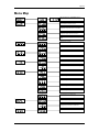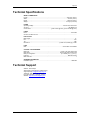
1
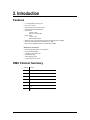
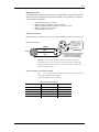
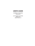
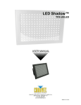
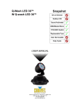
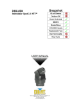
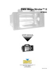
DMX-680
USER MANUAL
CHAUVET, 3000 N 29th Ct, Hollywood, FL 33020 U.S.A
(800) 762-1084 – (954) 929-1115
FAX (954) 929-5560
www.chauvetlighting.com
2006-10-10/18:04
Table of Contents
1. BEFORE YOU BEGIN....................................................................................................................................................... 3
UNPACKING INSTRUCTIONS.............................................................................................................................................................................................. 3
CONTACT US ................................................................................................................................................................................................................... 3
IMPORTANT SAFETY INFORMATION ................................................................................................................................................................................... 4
2. INTRODUCTION ............................................................................................................................................................... 5
FEATURES ....................................................................................................................................................................................................................... 5
DMX CHANNEL SUMMARY ............................................................................................................................................................................................... 5
PRODUCT OVERVIEW....................................................................................................................................................................................................... 6
3. SETUP ............................................................................................................................................................................... 7
AC POWER ..................................................................................................................................................................................................................... 7
LAMP INSTALLATION ........................................................................................................................................................................................................ 7
Lamp Installation ................................................................................................................................................................................................ 7
MOUNTING ...................................................................................................................................................................................................................... 8
FIXTURE LINKING ............................................................................................................................................................................................................. 8
Data Cabling ............................................................................................................................................................................................................ 8
DMX Data Cable................................................................................................................................................................................................. 9
Cable Connectors............................................................................................................................................................................................... 9
3-Pin to 5-Pin Conversion Chart ........................................................................................................................................................................ 9
SETTING UP A DMX SERIAL DATA LINK .......................................................................................................................................................................... 10
STANDALONE/MASTER-SLAVE FIXTURE LINKING ............................................................................................................................................................ 10
4. OPERATING INSTRUCTIONS........................................................................................................................................ 11
NAVIGATING THE CONTROL PANEL ................................................................................................................................................................................. 11
CONTROL & OPERATING MODE (N.O.D.E.)..................................................................................................................................................................... 11
DMX Mode (N-dN) ................................................................................................................................................................................................. 11
Stand-Alone, Master-Slave (N-So, N-SL, N-Au) ................................................................................................................................................... 12
DMX ADDRESSING (A.D.D.R.)........................................................................................................................................................................................ 12
USER CONFIGURATIONS ................................................................................................................................................................................................ 13
Individual Pan & Tilt Reverse (r.P.A.n., r.t.il.t.) ...................................................................................................................................................... 13
Combined Pan & Tilt Reverse (r.-.P.t.) .................................................................................................................................................................. 13
SERVICE FUNCTIONS ..................................................................................................................................................................................................... 14
Testing function (t.E.S.t.) ....................................................................................................................................................................................... 14
Reverse the segment display (d.S.P.L.) ................................................................................................................................................................ 14
Fixture reset (r.E.S.t.)............................................................................................................................................................................................. 14
5. APPENDIX....................................................................................................................................................................... 15
DMX PRIMER ................................................................................................................................................................................................................ 15
RETURNS PROCEDURE .................................................................................................................................................................................................. 15
CLAIMS ......................................................................................................................................................................................................................... 15
MAINTENANCE ............................................................................................................................................................................................................... 15
DMX CHANNEL VALUES ................................................................................................................................................................................................ 16
MENU MAP .................................................................................................................................................................................................................... 17
TECHNICAL SPECIFICATIONS .......................................................................................................................................................................................... 18
TECHNICAL SUPPORT .................................................................................................................................................................................................... 18
©CHAUVET, 2006, All Rights Reserved
Information and specifications in this User Manual are subject to change without
notice. CHAUVET assumes no responsibility or liability for any errors or
inaccuracies that may appear in this manual.
DMX-680 User Manual
2
2006-10-10/18:04
1. Before You Begin
Unpacking Instructions
Immediately upon receiving a product, carefully unpack the carton, check the contents to ensure that
all parts are present, and have been received in good condition. Notify the shipper immediately and
retain packing material for inspection if any parts appear damaged from shipping or the carton itself
shows signs of mishandling. Save the carton and all packing materials. In the event that a fixture
must be returned to the factory, it is important that the fixture be returned in the original factory box
and packing.
If you should require sending any items back to CHAUVET, call CHAUVET for a
Note:
(RMA) Return Merchandise Authorization number. The factory will not allow any shipments without
an RMA.
Your shipment includes the following:
1 x Intimidator Spot™ DMX-680
1 x ELC 24v 250w lamp
1 x Power cable
2 x brackets
Warranty Card
Users Manual
Contact Us
World Wide
General Information
Chauvet Lighting
th
3000 North 29 Court
Hollywood, FL 33020
voice:
954.929.1115
fax:
954.929.5560
toll free: 800.762.1084
Technical Support
Chauvet Lighting
th
3000 North 29 Court
Hollywood, FL 33020
World Wide Web
DMX-680 User Manual
voice:
954.929.1115 (Press 4)
fax:
954.929.5560 (Attention: Service)
www.chauvetlighting.com
3
2006-10-10/18:04
Before You Begin
Important Safety Information
This product is designed for professional use. It is not intended for use in a household environment.
This product presents risks of lethal or severe injury due to fire and heat, electric shock, ultraviolet
radiation, lamp explosion, and injury from falls. Read this manual before installing or powering the
fixture, follow the safety precautions listed below and observe all warnings in this manual and on the
fixture. If you have any questions about how to operate the fixture safely, please contact CHAUVET.
Protection against Electric Shock
•
Always disconnect from AC power source before servicing or replacing lamp or fuse and be sure
to replace with same lamp source.
•
All Class I fixtures must be connected to circuits with a suitable Earth Ground.
•
To prevent risk of fire or shock, do not expose fixture to rain or moisture. Make sure there are no
flammable materials close to the unit while operating.
•
Do not operate the fixture if covers are open or if any internal component is missing or damaged:
an unshielded discharge lamp emits dangerous UV radiation that can cause burns and eye
damage.
•
Make sure power cord is never crimped or damaged.
•
Never disconnect power cord by pulling or tugging on the cord.
Protection against Fire & Burns
•
This product is designed to be used with very specific lamp(s). Use of any other type of lamp not
stated in this manual may create a fire hazard due to possible risk of lamp explosion. Using the
wrong type of lamp in this product VOIDS the warranty.
•
Always make sure that you are connecting to the proper voltage and that the line voltage you are
connecting to is not higher than that stated on decal or rear panel of the fixture.
•
The unit must be installed in a location with adequate ventilation, at least 50cm from adjacent
surfaces. Be sure that no ventilation slots are blocked.
•
Maintain a minimum distance of 1 meter (3.28 feet) from combustible materials.
•
Allow this product to cool for a minimum of 15 minutes before opening, handling or removing the
lamp in this product.
•
Maximum ambient temperature is Ta: 40°. Do not operate fixture at temperatures higher than
this.
P r o t e c t i o n a g a i n s t e x p o s u r e t o ( U V ) U l t r a vi o l e t R a d i a t i o n
•
Avoid direct eye exposure to lamp while it is on.
•
Do not operate the fixture if covers are open or if any internal component is missing or damaged.
Protection against Injury to persons
Caution!
DMX-680 User Manual
•
Secure fixture to fastening device using a safety chain.
•
A hot lamp is an explosion hazard. Do not open fixture for a minimum of 15 minutes after
switching off. Wear eye and hand protection when re-lamping.
•
Fixture surface may reach temperatures of up to 160° C (320° F). Handle fixture after it cools.
•
In the event of serious operating problem, stop using the unit immediately. Never try to repair the
unit by yourself. Repairs carried out by unskilled people can lead to damage or malfunction.
Please contact the nearest authorized technical assistance center. Always use the same type
spare parts.
There are no user serviceable parts inside the unit. Do not open the housing or
attempt any repairs yourself. In the unlikely event your unit may require service,
please contact CHAUVET.
4
2006-10-10/18:04
2. Introduction
Features
•
•
•
•
•
•
•
•
•
7-channel DMX-512 moving yoke
o
o
Pan: 510 / tilt: 260
Pan/tilt speed & reset control channel
Mechanical dimmer/shutter/strobe
Color wheel:
8 colors + white
Rainbow color spin effect
Gobo wheel:
7 gobos + open
Gobo wheel spin effect
Blackout, reset, sound activation and built-in automatic programs via DMX
Built-in automated programs via master/slave or DMX
Built-in sound activated programs via master/slave or DMX
Ad d i t i o n a l F e a t u r e s
•
•
•
•
•
•
Dual hanging brackets with ¼-turn fasteners
Compact and lightweight
LED display menu with invert
Pan/tilt invert option
Micro-stepping motors
Thermal switch & fan cooled
DMX Channel Summary
DMX-680 User Manual
Channel
Function
1
Auto-programs, Lamp ON/OFF
2
Dimmer
3
Color
4
Gobo
5
Vector Speed
6
Pan
7
Tilt
5
2006-10-10/18:04
Introduction
Product Overview
Projector Head
Focusing lens gun
Yoke Arm
Carrying Handles
Rubber feet
Green LED:
DMX Signal Indicator
LED Control Panel
Fuse Compartment
Clamp brackets with ¼ turn locks
DMX Input
DMX-680 User Manual
6
Power cable
DMX Output
2006-10-10/18:04
3. Setup
AC Power
Warning!
Verify that the power requirement label on your unit matches the line voltage
applied. All fixtures must be connected to circuits with a suitable Earth Ground.
• To determine the power requirements for a particular fixture, see the label affixed to the back plate
of the fixture or refer to the fixture’s specifications chart.
• A fixture’s listed current rating is its average current draw under normal conditions.
• All fixtures must be powered directly off a switched circuit and cannot be run off a rheostat
(variable resistor) or dimmer circuit, even if the rheostat or dimmer channel is used solely for a 0%
to 100% switch.
• Before applying power to a fixture, check that the source voltage matches the fixture’s
requirement.
• All fixtures must be connected to circuits with a suitable Earth Ground.
P ow e r C a b l e C o n f i g u r a t i o n
CABLE
Pin
International
Screw Color
BROWN
Live
L
Yellow or Brass
BLUE
Neutral
N
Silver
YELLOW/GREEN
Earth
EG (Ground)
Green
Lamp Installation
You will need to install a lamp prior to the initial operation of the fixture.
Warning!
When replacing the lamp, please wait 15 minutes after powering down to allow the
unit to cool down! Always disconnect from main power prior to lamp replacement.
S1
Lamp Installation
1. Remove screws labeled (S1) and pull out lamp
socket plate.
2. If replacing the lamp, remove old lamp first.
3. Release the retaining clips as shown on figure 1.
Both the lamp along with the socket will be
released.
4. Detach the lamp from the socket and replace the
lamp.
5. Place the lamp back into the lamp cage and secure
the clips back in place.
6. There is no lamp alignment since the lamp is already
optimized inside a mirrored dichroic reflector.
7. Insert lamp socket plate back into the rear of the fixture and tighten
screws to complete installation.
1
DMX-680 User Manual
7
2006-10-10/18:04
Setup
Mounting
Orientation
This fixture can be mounted on a truss using a clamp in any position or against a flat surface using
the brackets provided.
Rigging
The fixture includes two brackets with ¼ turn locks for attaching a
Hanging Clamp
standard truss mounting hanging clamp. You must supply your own
clamp and make sure the clamp is capable of supporting the weight
of this fixture. You can order C-clamps from any CHAUVET dealer
or distributor.
1.
Block access below the work area and use suitable and
stable platform when installing or servicing fixture.
2.
Align the clamp screw with the center hole on the yoke and
tighten.
3.
Verify the structure can hold 10 times the weight of all to-be
installed fixtures.
4.
Adjust the angle on the yoke arm as necessary.
5.
Always use a safety cable or chain as a secondary source of
attachment. The safety cable must hold 10 times the weight
of the fixture. If safety cable attachment point is provided
that is permanently affixed to the surface or body of the
fixture, use that instead of looping through a hanging
yoke/arm.
Fixture Linking
You will need a serial data link to run light shows of one or more fixtures using a DMX-512 controller
or to run synchronized shows on two or more fixtures set to a master/slave operating mode. The
combined number of channels required by all the fixtures on a serial data link determines the number
of fixtures the data link can support.
The DMX-680 fixtures use 7 channels of DMX control.
Important: Fixtures on a serial data link must be daisy chained in one single line. To comply with
the EIA-485 standard no more than 32 devices should be connected on one data link. Connecting
more than 32 fixtures on one serial data link without the use of a DMX optically isolated splitter may
result in deterioration of the digital DMX signal.
Maximum recommended serial data link distance: 500 meters (1640 ft.)
Maximum recommended number of fixtures on a serial data link: 32 fixtures
Data Cabling
To link fixtures together you must obtain data cables. You can purchase CHAUVET certified DMX
cables directly from a dealer/distributor or construct your own cable. If you choose to create your own
cable please use data-grade cables that can carry a high quality signal and are less prone to
electromagnetic interference.
DMX-680 User Manual
8
2006-10-10/18:04
Setup
DMX Data Cable
Use a Belden© 9841 or equivalent cable which meets the specifications for EIA RS-485 applications.
Standard microphone cables cannot transmit DMX data reliably over long distances. The cable will
have the following characteristics:
•
•
•
•
•
2-conductor twisted pair plus a shield
Maximum capacitance between conductors – 30 pF/ft.
Maximum capacitance between conductor and shield – 55 pF/ft.
Maximum resistance of 20Ω / 1000 ft.
Nominal impedance 100 - 140Ω
Cable Connectors
Cabling must have a male XLR connector on one end and a female XLR connector on the other end.
1
3
2
DMX connector configuration
COMMON
INPUT
1
3
1
3
DMX +
OUTPUT
Termination reduces signal errors and
to avoid signal transmission problems
and interference, it is always
advisable to connect a DMX signal
2
2
Resistance 120
ohm 1/4w between
pin 2 (DMX -) and
pin 3 (DMX +) of
the last fixture.
DMX -
CAUTION Do not allow contact between the common and the fixture’s chassis ground.
Grounding the common can cause a ground loop and your fixture to perform erratically. Test
cables with OHM meter to verify correct polarity and to make sure the pins are not grounded or
shorted to the shield or each other.
3 - P i n t o 5 - P i n C o n ve r s i o n C h a r t
Note!
If you use a controller with a 5 pin DMX output connector, you will need to use a 5 pin
to 3 pin adapter. CHAUVET Model No: DMX5M.
The chart below details a proper cable conversion:
3 PIN TO 5 PIN CONVERSION CHART
DMX-680 User Manual
Conductor
3 Pin Female (output)
5 Pin Male (Input)
Ground/Shield
Pin 1
Pin 1
Data ( - )signal
Pin 2
Pin 2
Data ( + ) signal
Pin 3
Pin 3
Do not use
Do not use
Do not use
Do not use
9
2006-10-10/18:04
Setup
Setting up a DMX Serial Data Link
1. Connect the (male) 3 pin connector side of
the DMX cable to the output (female) 3 pin
connector of the controller.
Universal DMX Controller
2. Connect the end of the cable coming from
the controller which will have a (female) 3
pin connector to the input connector of the
next fixture consisting of a (male) 3 pin
connector.
3. Then, proceed to connect from the output
as stated above to the input of the following
fixture and so on.
This drawing provides a
general illustration of the
DMX Input/Output panel
of a lighting fixture.
CHAUVET Certified DMX Data Cables
Order Code
Description
DMX1.5
DMX Cable 1.5m/4.9ft
DMX4.5
DMX Cable 4.5m/14.8ft
DMX10
DMX Cable 10m/32.8ft
Continue the link
Standalone/Master-Slave
Fixture Linking
1. Connect the (male) 3 pin connector side of the DMX cable to the output (female) 3 pin connector
of the first fixture.
2. Connect the end of the cable coming from the first fixture which will have a (female) 3 pin
connector to the input connector of the next fixture consisting of a (male) 3 pin connector. Then,
proceed to connect from the output as stated above to the input of the following fixture and so on.
Fixtures displayed are for illustration purpose only!
Often, the setup for Master-Slave
and Standalone operation
requires that the first fixture in the
chain be initialized for this
purpose via either settings in the
control panel or DIP-switches.
Secondarily the fixtures that
follow may also require a slave
setting. Please consult the
“Operating Instructions” section
in this manual for complete
instructions for this type of setup
and configuration.
DMX-680 User Manual
10
2006-10-10/18:04
4. Operating Instructions
Navigating the Control Panel
Access control panel functions using the four panel buttons
Button
Function
<Down>
Used to access the menu or to return to a previous
menu option
Scrolls through menu options in descending order
<Up>
Scrolls through menu options in ascending order
<Enter>
Used to select and store the current menu or
option within a menu
<Fun>
located directly underneath the LED
Display.
The Control Panel LED Display shows the menu items you select from the menu map. To see a table
of all menu functions please visit the “Menu Map Table” on page 16. When a menu function is
selected, the display will show immediately the first available option for the selected menu function.
Press the <Fun> button until Addr appears on the display, this is the top of the menu map. Use the
<Up>/<Down> buttons to navigate the menu map and menu options. Press the <Enter> button to
access the menu function currently displayed or to enable a menu option. To return to the previous
option or menu without changing the value, press the <Fun> button.
Control & Operating Mode (N.o.d.E.)
The DMX-680 has four control or operating modes that must be defined in each
fixture in order to work correctly under stand-alone, master-slave or manual DMX
control. Please set the control mode according to your specific requirements.
DMX Mode (N-dN)
MENU OPTION
DESCRIPTION
DMX Mode: Sets the fixture to accept and operate in DMX control mode
DMX-680 User Manual
11
2006-10-10/18:04
Operating Instructions
Stand-Alone, Master-Slave (N-So, N-SL, N-Au)
A master-slave mode setup consists of more than one fixture connected in a serial data link without
the use of a controller. In a master-slave operation the slave fixtures will synchronize and will behave
either identically or in a planned chase pattern to the master unit which must be the first in the serial
daisy chain. A Master-Slave system can consist of an unlimited range of fixtures or at least the
number stated to conform to EIA-485 standards.
MENU OPTION
DESCRIPTION
Sound Active – Master Unit: Sets the fixture to Master status for Master-Slave operation and the
built in programs will be triggered by the sound. No data link is required; all fixtures can be set to
this mode for Stand-alone operation.
Sound Active – Slave Unit: Sets the fixture to run in sync with the Master. You must set the first
fixture in the data link to “Master” otherwise nothing will happen.
Stand Alone – Automatic: The built in programs will trigger automatically to a pre-programmed
speed time.
DMX Addressing (A.d.d.r.)
DMX mode enables the use of a universal DMX controller device. Each fixture
requires a "start address" from 1 to 511. A fixture requiring one or more channels
for control begins to read the data on the channel indicated by the start address.
For example, a fixture that occupies or uses 6 channels of DMX and was addressed to start on DMX
channel 100, would read data from channels: 100, 101, 102, 103, 104, and 105. Choose start
addresses so that the channels used do not overlap and notate the start address selected for future
reference.
If this is your first time addressing a fixture using the DMX-512 control protocol than I suggest jumping
to the Appendix Section and read the heading “DMX Primer”. It contains very useful information that
will help you understand its use.
Note: In order to operate in DMX control mode you must first set the fixture to operate in this
mode by setting the N-dN option in the Mode (NodE) function.
Setting the start address
1. Press the <Fun> button until Addr appears on the Display. Press
the <Enter> button to select.
2. Use the <Down> and <Up> buttons to increase or decrease
channel values until the desired start channel value is located.
Four small LEDs dots will blink during the selection process.
Blinks during selection
3. Press the <Enter> button to accept the new start channel. The
four small LED dots will cease to blink to confirm selection.
DMX-680 User Manual
12
2006-10-10/18:04
Operating Instructions
User Configurations
Individual Pan & Tilt Reverse (r.P.A.n., r.t.il.t.)
It is possible to invert the pan and tilt mirror movement from within the fixture
itself. This could be helpful in situations where the positioning or rigging of a
fixture led to a reverse orientation of the fixture in relation to all or most other
fixtures installed. When choosing to command the pan or tilt of all fixtures at the
same time you will notice that the fixtures whose orientation is different from the others will most likely
move opposite of the rest. You can apply a pan and tilt Invert by following the settings in the table
below.
MENU
LEVEL 1
OPTION
LEVEL 2
DESCRIPTION
Standard Pan Movement: Normal left to right
Reverse Pan Movement: Inverted movement from right to left
Standard Tilt Movement: Normal setting
Reverse Tilt Movement: Inverted setting
Combined Pan & Tilt Reverse (r.-.P.t.)
MENU
LEVEL 1
OPTION
LEVEL 2
DESCRIPTION
Standard Pan/Tilt Movement: Normal setting
Combined
Settings
DMX-680 User Manual
Reverse Pan/Tilt Movement: Inverted setting
13
2006-10-10/18:04
Operating Instructions
Service Functions
Testing function (t.E.S.t.)
The TEST function provides the user a method for testing the fixtures mechanical
components through the control panel. Press and hold the <Enter> button while
on the specific menu option to test.
MENU OPTION
DESCRIPTION
Tilt: Testing of the Tilt movement
Pan: Testing of the Pan movement
Color: Tests the color wheel
Gobo: Tests the gobo wheel
Shutter: Tests the shutter
Reverse the segment display (d.S.P.L.)
You can rotate the display 180° so that it becomes easier to read when the fixture
is positioned upside down.
MENU OPTION
DESCRIPTION
Standard: Standard display orientation
Reverse: Rotated display orientation
Fixture reset (r.E.S.t.)
This function will re-initialize the fixture by returning all motors to its startup
positions or otherwise known as (home position).
DMX-680 User Manual
14
2006-10-10/18:04
5. Appendix
DMX Primer
There are 512 channels in a DMX-512 connection. Channels may be assigned in any manner. A
fixture capable of receiving DMX-512 will require one or a number of sequential channels. The user
must assign a starting address on the fixture that indicates the first channel reserved in the controller.
There are many different types of DMX controllable fixtures and they all may vary in the total number
of channels required. Choosing a start address should be planned in advance. Channels should
never overlap. If they do, this will result in erratic operation of the fixtures whose starting address is
set incorrectly. You can however, control multiple fixtures of the same type using the same starting
address as long as the intended result is that of unison movement or operation. In other words, the
fixtures will be slaved together and all respond exactly the same.
DMX fixtures are designed to receive data through a serial Daisy Chain. A Daisy Chain connection is
where the DATA OUT of one fixture connects to the DATA IN of the next fixture. The order in which
the fixtures are connected is not important and has no effect on how a controller communicates to
each fixture. Use an order that provides for the easiest and most direct cabling. Connect fixtures
using shielded two conductor twisted pair cable with three pin XLR male to female connectors. The
shield connection is pin 1, while pin 2 is Data Negative (S-) and pin 3 is Data positive (S+). CHAUVET
carries 3-pin XLR DMX compliant cables, DMX-10 (33’), DMX-4.5 (15’) and DMX-1.5 (5’)
Returns Procedure
Returned merchandise must be sent prepaid and in the original packing, call tags will not be issued.
Package must be clearly labeled with a Return Merchandise Authorization Number (RA #). Products
returned without an RA # will be refused. Call CHAUVET and request RA # prior to shipping the
fixture. Be prepared to provide the model number, serial number and a brief description of the cause
for the return. Be sure to properly pack fixture, any shipping damage resulting from inadequate
packaging is the customer’s responsibility. CHAUVET reserves the right to use its own discretion to
repair or replace product(s). As a suggestion, proper UPS packing or double-boxing is always a safe
method to use.
Claims
Damage incurred in shipping is the responsibility of the shipper; therefore the damage must be
reported to the carrier upon receipt of merchandise. It is the customer's responsibility to notify and
submit claims with the shipper in the event that a fixture is damaged due to shipping. Any other claim
for items such as missing component/part, damage not related to shipping, and concealed damage,
must be made within seven (7) days of receiving merchandise.
Maintenance
To maintain optimum performance and minimize wear, fixtures should be cleaned frequently. Usage
and environment are contributing factors in determining frequency. As a general rule, fixtures should
be cleaned at least twice a month. Dust build up reduces light output performance and can cause
overheating. This can lead to reduced lamp life and increased mechanical wear. Be sure to power off
fixture before conducting maintenance.
DMX-680 User Manual
15
2006-10-10/18:04
Appendix
Unplug fixture from power. Use a vacuum or air compressor and a soft brush to remove dust
collected on external vents and internal components. Clean all glass when the fixture is cold with a
mild solution of glass cleaner or Isopropyl Alcohol and a soft lint free cotton cloth or lens tissue. Apply
solution to the cloth or tissue and drag dirt and grime to the outside of the lens. Gently polish optical
surfaces until they are free of haze and lint. Do not to touch the lamp glass when cleaning fixture. Oil
and dirt can cause damage and premature aging of the lamp. In the event that the lamp is touched or
becomes dirty, clean the lamps with an alcohol wipe.
The cleaning of internal and external optical lenses and/or mirrors must be carried out periodically to
optimize light output. Cleaning frequency depends on the environment in which the fixture operates:
damp, smoky or particularly dirty surrounding can cause greater accumulation of dirt on the unit’s
optics. Clean with soft cloth using normal glass cleaning fluid. - Always dry the parts carefully. - Clean
the external optics at least every 20 days. Clean the internal optics at least every 30/60 days.
DMX Channel Values
CHANNEL
DMX-680 User Manual
VALUE
FUNCTION
1
000 Ù 127
128 Ù 179
180 Ù 223
224 Ù 250
251 Ù 255
Control/Operating Mode
DMX Mode
Stand-alone (automatic)
Stand-alone (sound active)
Lamp turn on (after 10 seconds)
Lamp shut off (after 10 seconds)
2
000 Ù 019
020 Ù 127
128 Ù 239
240 Ù 255
Dimmer/Shutter
Blackout
Dimmer: 0% <> 100%
Strobe: Fast > Slow > Fast
Open
3
000 Ù 015
016 Ù 031
032 Ù 043
044 Ù 055
056 Ù 067
068 Ù 079
080 Ù 091
092 Ù 107
108 Ù 119
120 Ù 135
136 Ù 151
152 Ù 167
168 Ù 183
184 Ù 199
200 Ù 215
216 Ù 227
228 Ù 239
240 Ù 255
Color Wheel
White (Open)
Pink
Orange
Light Blue
Magenta
Yellow
Blue
Green
Red
Red/green
Green/blue
Blue/yellow
Yellow/magenta
Magenta/light blue
Light blue/orange
Orange/pink
Pink/white
Color scroll: Slow > Fast
4
000 Ù 023
024 Ù 047
048 Ù 071
072 Ù 095
096 Ù 119
120 Ù 143
144 Ù 167
168 Ù 191
192 Ù 255
Gobo Wheel
Open
Leaves
3D sphere
Flowers
Shapes
Maze
Mini triangles
Atomic
Gobo scroll: Fast > Slow
5
000 Ù 255
Vector Speed: (Normal > Slow)
6
000 Ù 255
Pan: 128 = halfway point
7
000 Ù 255
Tilt: 128 = halfway point
16
2006-10-10/18:04
Appendix
Menu Map
<>
DMX 512 addressing. Use Up/Down buttons to
change DMX values between 001 and 512.
Sets the fixture to operate under DMX-512 control. A
Universal DMX controller is required.
Assigns Master status to fixture for Master-Slave
configuration. Programs will run in sound-active.
Assigns Slave status to fixture for Master-Slave
configuration. Start from fixture # 2 and on.
Stand-Alone mode running at an automatic preset
speed.
Standard pan movement
Reverse pan movement
Standard tilt movement
Reverse tilt movement
Combined control of pan & tilt, standard default
Combined control of pan & tilt, reversed settings
Tests all motors in the fixture
Provides testing of the pan movement
Provides testing of the tilt movement
Provides testing of the color wheel
Provides testing of the gobo wheel
Provides testing of the shutter blade
Standard display setting
Inversed or reversed display setting. Useful for
reading display while fixture is upside down.
Fixture reset
DMX-680 User Manual
17
2006-10-10/18:04
Appendix
Technical Specifications
WEIGHT & DIMENSIONS
Length........................................................................................................................ 406.4 mm (16.0 in)
Width ............................................................................................................................ 254 mm (10.0 in)
Height .......................................................................................................................... 228.6 mm (9.0 in)
Weight ..................................................................................................................... 5.79 Kgs (12.76 lbs)
POWER
Operating Voltage .........................................................................................110V 60 Hz or 230V 50 Hz
AC input........................................................................................................................... IEC 60320 C14
Current draw............................................................... (peak <312W @ 120V), (inrush <456W @ 120V)
LAMPS
ELC3........................................................................................................................................ 24V 250W
Can also use ELC & ELC5 .......................................................................................................................
PHOTO OPTIC
Beam Angle ........................................................................................................................................ 11°
Pan ................................................................................................................................................... 510°
Tilt..................................................................................................................................................... 260°
Illuminance ..........................................................................................(2,330fc or 25,070lux) @ 1 meter
FUSE
Main............................................................................................................... 20mm Glass 7A Fast Blow
CONTROL & PROGRAMMING
Data input ................................................................................................ locking 3-pin XLR male socket
Data output ........................................................................................... locking 3-pin XLR female socket
Data pin configuration ..............................................................................pin 1 shield, pin 2 (-), pin 3 (+)
Protocols........................................................................................................................ DMX-512 USITT
DMX Channels .......................................................................................................................................7
ORDERING INFORMATION
Intimidator Spot™......................................................................................................................DMX-680
Technical Support
Address: Service Dept.
3000 N 29th Ct, Hollywood, FL 33020 (U.S.A.)
Support (Email): [email protected]
Telephone: (954) 929-1115 - (Press 4)
Fax: (954) 929-5560 - (Attention: Service)
Website: http://www.chauvetlighting.com
DMX-680 User Manual
18
2006-10-10/18:04