1
Instruction Manual
PN 51-Xmt-P/rev.E
October 2007
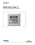
Model Solu Comp Xmt-P
pH, ORP, and Redox Transmitter
ESSENTIAL INSTRUCTIONS
READ THIS PAGE BEFORE PROCEEDING!
Rosemount Analytical designs, manufactures, and tests its products to meet many national and international
standards. Because these instruments are sophisticated technical products, you must properly install, use, and
maintain them to ensure they continue to operate within their normal specifications. The following instructions
must be adhered to and integrated into your safety program when installing, using, and maintaining Rosemount
Analytical products. Failure to follow the proper instructions may cause any one of the following situations to
occur: Loss of life; personal injury; property damage; damage to this instrument; and warranty invalidation.
• Read all instructions prior to installing, operating, and servicing the product. If this Instruction Manual is not the
correct manual, telephone 1-800-654-7768 and the requested manual will be provided. Save this Instruction
Manual for future reference.
• If you do not understand any of the instructions, contact your Rosemount representative for clarification.
• Follow all warnings, cautions, and instructions marked on and supplied with the product.
• Inform and educate your personnel in the proper installation, operation, and maintenance of the product.
• Install your equipment as specified in the Installation Instructions of the appropriate Instruction Manual and per
applicable local and national codes. Connect all products to the proper electrical and pressure sources.
• To ensure proper performance, use qualified personnel to install, operate, update, program, and maintain the
product.
• When replacement parts are required, ensure that qualified people use replacement parts specified by
Rosemount. Unauthorized parts and procedures can affect the product’s performance and place the safe
operation of your process at risk. Look alike substitutions may result in fire, electrical hazards, or improper
operation.
• Ensure that all equipment doors are closed and protective covers are in place, except when maintenance is
being performed by qualified persons, to prevent electrical shock and personal injury.
NOTICE
If a Model 375 Universal Hart® Communicator is used with these transmitters, the software within the Model 375 may require
modification. If a software modification is required, please contact your local Emerson Process Management Service Group
or National Response Center at 1-800-654-7768.
About This Document
This manual contains instructions for installation and operation of the Model Xmt-P Two-Wire pH/ORP
Transmitter. The following list provides notes concerning all revisions of this document.
Rev. Level
Date
Notes
A
3/05
This is the initial release of the product manual. The manual has been
reformatted to reflect the Emerson documentation style and updated to
reflect any changes in the product offering. This manual contains
information on HART Smart and FOUNDATION Fieldbus versions of
Model Solu Comp Xmt-P.
B
9/05
Revise panel mount drawing. Add Foundation fieldbus agency
approvals and FISCO version.
C
2/06
Revised the case specification on page 2. Added new drawings of FF
and FI on section 4.0, pages 29-46.
D
6/06
Revised Quick Start choices adding language as #5. Added Language
box to page 5. Deleted 230A in accessories chart on page 10.
E
10/07
Emerson Process Management
Liquid Division
2400 Barranca Parkway
Irvine, CA 92606 USA
Tel: (949) 757-8500
Fax: (949) 474-7250
http://www.raihome.com
© Rosemount Analytical Inc. 2006
Added M Certs to page 2.
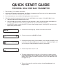
QUICK START GUIDE
FOR MODEL SOLU COMP Xmt-P TRANSMITTER
1. Refer to page 11 for installation instructions.
2. Wire pH or ORP sensor to the transmitter. See Figure 2-3 for panel mount; Figure 2-4 or 2-5 for pipe or surface
mount. Refer to the sensor instruction sheet for details.
3. Once connections are secure and verified, apply power to the transmitter.
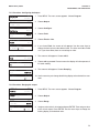
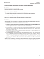
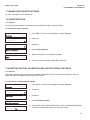
4. When the transmitter is powered up for the first time, Quick Start screens appear. Using Quick Start is easy.
a. A blinking field shows the position of the cursor.
b. Use the t or u key to move the cursor left or right. Use the p or q key to move the cursor up or down or to
increase or decrease the value of a digit. Use the p or q key to move the decimal point.
c.
Press ENTER to store a setting. Press EXIT to leave without storing changes. Pressing EXIT also returns the
display to the previous screen.
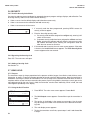
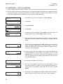
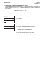
English
Español
Français
>>
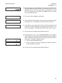
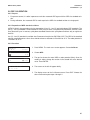
Measure?
pH
Redox
Sensor/JBox
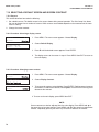
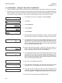
7. Choose preamplifier location. Select Xmtr to use the integral preamplifier in the
transmitter; select Sensor/JBox if your sensor has an integral preamplifier or if
you are using a remote preamplifier located in a junction box.
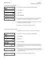
8. Choose temperature units: °C or °F.
Temperature in?
°C
6. Choose measurement: pH, ORP, or Redox.
ORP
Use Preamp in?
Xmtr
5. Choose the desired language. Choose >> to show more choices.
°F
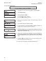
9. To change output settings, to scale the 4-20 mA output, to change measurement-related settings from the default values, and to set security codes, press
MENU. Select Program and follow the prompts. Refer to the appropriate menu
tree (page 5 or 6).
9. To return the transmitter to default settings, choose ResetAnalyzer in the
Program menu.
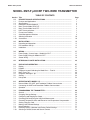
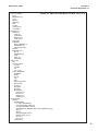
MODEL XMT-P pH/ORP
TABLE OF CONTENTS
MODEL XMT-P pH/ORP TWO-WIRE TRANSMITTER
TABLE OF CONTENTS
Section
1.0
1.1
1.2
1.3
1.4
1.5
1.6
1.7
1.8
1.9
1.10
Title
DESCRIPTION AND SPECIFICATIONS ................................................................
Features and Applications........................................................................................
Specifications ...........................................................................................................
Hazardous Location Approval ..................................................................................
Menu Tree for Model Xmt-P-HT...............................................................................
Menu Tree for Model Xmt-P-FF ...............................................................................
HART Communications............................................................................................
FOUNDATION Fieldbus ..............................................................................................
Asset Management Solutions .................................................................................
Ordering Information ...............................................................................................
Accessories .............................................................................................................
Page
1
1
2
4
5
6
7
7
8
10
10
2.0
2.1
2.2
2.3
INSTALLATION .......................................................................................................
Unpacking and Inspection........................................................................................
Pre-Installation Set Up .............................................................................................
Installation................................................................................................................
11
11
11
13
3.0
3.1
3.2
3.2
WIRING....................................................................................................................
Power Supply / Current Loop — Model Xmt-P-HT ..................................................
Power Supply Wiring for Model Xmt-P-FF ...............................................................
Sensor Wiring ..........................................................................................................
17
17
18
19
4.0
INTRINSICALLY SAFE INSTALLATION.................................................................
20
5.0
5.1
5.2
5.3
5.4
5.5
5.6
5.7
DISPLAY AND OPERATION ...................................................................................
Display .....................................................................................................................
Keypad.....................................................................................................................
Programming and Calibrating the Model Xmt — Tutorial.........................................
Menu Trees - pH ......................................................................................................
Diagnostic Messages - pH .......................................................................................
Security ....................................................................................................................
Using Hold ...............................................................................................................
47
47
47
48
49
49
52
52
6.0
6.1
6.2
6.3
OPERATION WITH MODEL 375.............................................................................
Note on Model 375 HART and Foundation Fieldbus Communicator .......................
Connecting the HART and Foundation Fieldbus Communicator .............................
Operation .................................................................................................................
53
53
53
54
7.0
7.1
7.2
7.3
7.4
7.5
7.6
7.7
7.8
7.9
7.10
PROGRAMMING THE TRANSMITTER..................................................................
General ....................................................................................................................
Changing Start-up Settings ......................................................................................
Configuring and Ranging the Output .......................................................................
Choosing and Configuring the Analytical Measurement ..........................................
Choosing Temperature Units and Manual or Auto Temperature Compensation ......
Setting a Security Code ...........................................................................................
Making HART-Related Settings ...............................................................................
Noise Reduction.......................................................................................................
Resetting Factory Calibration and Factory Default Settings ....................................
Selecting a Default Screen and Screen Contrast ....................................................
69
69
69
70
73
75
76
77
77
77
78
i
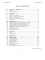
MODEL XMT-P pH/ORP
TABLE OF CONTENTS
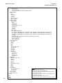
TABLE OF CONTENTS CONT’D
8.0
8.1
8.2
CALIBRATION — TEMPERATURE........................................................................
Introduction ..............................................................................................................
Calibrating Temperature...........................................................................................
79
79
79
9.0
9.1
9.2
9.3
9.4
9.5
9.6
CALIBRATION — pH .............................................................................................
Introduction ..............................................................................................................
Procedure — Auto Calibration .................................................................................
Procedure — Manual Two-Point Calibration............................................................
Procedure — Standardization ..................................................................................
Procedure — Entering a Known Slope Value ..........................................................
ORP Calibration .......................................................................................................
81
81
82
84
85
86
87
10.0
10.1
10.2
10.3
10.4
10.5
10.6
10.7
10.8
10.9
TROUBLESHOOTING ...........................................................................................
Overview ..................................................................................................................
Troubleshooting When a Fault or Warning Message is Showing ............................
Troubleshooting When No Fault Message is Showing — Temp ..............................
Troubleshooting When No Fault Message is Showing — HART .............................
Troubleshooting When No Fault Message is Showing — pH ..................................
Troubleshooting Not Related to Measurement Problems ........................................
Simulating Inputs — pH ...........................................................................................
Simulating Temperature ...........................................................................................
Measuring Reference Voltage..................................................................................
88
88
89
92
92
92
95
95
96
97
11.0
11.1
11.2
MAINTENANCE ......................................................................................................
Overview ..................................................................................................................
Replacement Parts ..................................................................................................
98
98
98
12.0
12.1
12.2
12.3
12.4
12.5
12.6
12.7
12.8
12.9
12.10
12.11
pH MEASUREMENTS.............................................................................................
General ....................................................................................................................
Measuring Electrode ................................................................................................
Reference Electrode ................................................................................................
Liquid Junction Potential ..........................................................................................
Converting Voltage to pH .........................................................................................
Glass Electrode Slope .............................................................................................
Buffers and Calibration ............................................................................................
Isopotential pH .........................................................................................................
Junction Potential Mismatch ....................................................................................
Sensor Diagnostics ..................................................................................................
Shields, Insulation, and Preamplifiers......................................................................
99
99
100
100
101
101
102
102
103
103
104
104
continued on following page
ii
MODEL XMT-P pH/ORP
TABLE OF CONTENTS
TABLE OF CONTENTS CONT’D
13.0
13.1
13.2
13.3
13.4
13.5
13.6
13.7
13.8
ORP MEASUREMENTS..........................................................................................
General ....................................................................................................................
Measuring Electrode ................................................................................................
Reference Electrode ................................................................................................
Liquid Junction Potential ..........................................................................................
Relating Cell Voltage to ORP...................................................................................
ORP, Concentration, and pH....................................................................................
Interpreting ORP Measurements .............................................................................
Calibration................................................................................................................
105
105
106
106
106
107
107
108
109
14.0
14.1
14.2
14.3
THEORY — REMOTE COMMUNICATIONS...........................................................
Overview of HART Communications........................................................................
HART Interface Devices...........................................................................................
Asset Management Solutions ..................................................................................
111
111
111
112
15.0
RETURN OF MATERIAL.........................................................................................
113
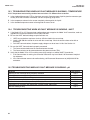
LIST OF TABLES
Number Title
11-1
Replacement Parts for Model Xmt-P — Panel Mount Version ................................
11-2
Replacement Parts for Model Xmt-P — Pipe/Surface Mount Version .....................
iii
Page
98
98
MODEL XMT-P pH/ORP
TABLE OF CONTENTS
LIST OF FIGURES
Number
1-1
1-2
1-3
1-4
1-5
2-1
2-2
2-3
2-4
2-5
3-1
3-2
3-3
3-4
3-5
4-1
4-2
4-3
4-4
4-5
4-6
4-7
4-8
4-9
4-10
4-11
4-12
4-13
4-14
4-15
4-16
4-17
4-18
4-19
4-20
4-21
4-22
4-23
4-24
4-25
4-26
4-27
5-1
5-2
5-3
5-4
6-1
6-2
6-3
Title
Menu Tree — Xmt-P-HT...........................................................................................
Menu Tree — Xmt-P-FF ...........................................................................................
Configuring Model XMT Transmitter with FOUNDATION Fieldbus ..............................
HART Communicators..............................................................................................
AMS Main Menu Tools .............................................................................................
Removing the Knockouts .........................................................................................
Power Supply / Current Loop Wiring ........................................................................
Panel Mount Installation ...........................................................................................
Pipe Mount Installation .............................................................................................
Surface Mount Installation ........................................................................................
Load/Power Supply Requirements ...........................................................................
Power Supply / Current Loop Wiring ........................................................................
Typical Fieldbus Network Electrical Wiring Configuration ........................................
Loop Power and Sensor Wiring................................................................................
Wiring and Preamplifier Configurations for pH and ORP Sensors ...........................
FM Intrinsically Safe Label for Model XMT-P-HT .....................................................
FM Intrinsically Safe Installation for Model XMT-P-HT (1 of 2) ................................
FM Intrinsically Safe Installation for Model XMT-P-HT (2 of 2) ................................
CSA Intrinsically Safe Label for Model XMT-P-HT ...................................................
CSA Intrinsically Safe Installation for Model XMT-P-HT (1 of 2) ..............................
CSA Intrinsically Safe Installation for Model XMT-P-HT (2 of 2) ..............................
ATEX Intrinsically Safe Label for Model XMT-P-HT .................................................
ATEX Intrinsically Safe Installation for Model XMT-P-HT (1 of 2) ............................
ATEX Intrinsically Safe Installation for Model XMT-P-HT (2 of 2) ............................
FM Intrinsically Safe Label for Model XMT-P-FF......................................................
FM Intrinsically Safe Installation for Model XMT-P-FF (1 of 2) ................................
FM Intrinsically Safe Installation for Model XMT-P-FF (2 of 2) ................................
CSA Intrinsically Safe Label for Model XMT-P-FF....................................................
CSA Intrinsically Safe Installation for Model XMT-P-FF (1 of 2) ..............................
CSA Intrinsically Safe Installation for Model XMT-P-FF (2 of 2) ..............................
ATEX Intrinsically Safe Label for Model XMT-P-FF..................................................
ATEX Intrinsically Safe Installation for Model XMT-P-FF (1 of 2) ............................
ATEX Intrinsically Safe Installation for Model XMT-P-FF (2 of 2) ............................
FM Intrinsically Safe Label for Model XMT-P-FI.......................................................
FM Intrinsically Safe Installation for Model XMT-P-FI (1 of 2) .................................
FM Intrinsically Safe Installation for Model XMT-P-FI (2 of 2) .................................
CSA Intrinsically Safe Label for Model XMT-P-FI.....................................................
CSA Intrinsically Safe Installation for Model XMT-P-FI (1 of 2) ...............................
CSA Intrinsically Safe Installation for Model XMT-P-FI (2 of 2) ...............................
ATEX Intrinsically Safe Label for Model XMT-P-FI ...................................................
ATEX Intrinsically Safe Installation for Model XMT-P-FI (1 of 2) .............................
ATEX Intrinsically Safe Installation for Model XMT-P-FI (2 of 2) .............................
Displays During Normal Operation...........................................................................
Solu Comp Xmt Keypad ...........................................................................................
Menu Tree for Model Xmt-P-HT ...............................................................................
Menu Tree for Model Xmt-P-FF................................................................................
Connecting the Model 375 Communicator ..............................................................
XMT-P-HT HART / Model 375 Menu Tree................................................................
XMT-P-HT Foundation Fieldbus / Model 375 Menu Tree .........................................
iv
Page
5
6
7
8
9
13
13
14
15
16
17
17
18
18
19
20
21
22
23
24
25
26
27
28
29
30
31
32
33
34
35
36
37
38
39
40
41
42
43
44
45
46
29
29
32
33
35
37
39
MODEL XMT-P pH/ORP
TABLE OF CONTENTS
LIST OF FIGURES CONT’D
Number Title
9-1
10-1
10-2
10-3
10-4
12-1
12-2
12-3
12-4
12-5
12-6
12-7
12-8
13-1
13-2
13-3
13-4
13-5
13-6
14-1
14-2
Page
Calibration Slope and Offset ....................................................................................
Simulate pH..............................................................................................................
Three-Wire RTD Configuration.................................................................................
Simulating RTD Inputs .............................................................................................
Checking for a Poisoned Reference Electrode ........................................................
pH Measurement Cell...............................................................................................
Measuring Electrode (pH) ........................................................................................
Cross-Section Through the pH Glass.......................................................................
Reference Electrode.................................................................................................
The Origin of Liquid Junction Potential.....................................................................
Glass Electrode Slope..............................................................................................
Two-Point Buffer Calibration.....................................................................................
Liquid Junction Potential Mismatch ..........................................................................
ORP Measurement Cell ...........................................................................................
Measuring Electrode (ORP) .....................................................................................
Reference Electrode.................................................................................................
The Origin of Liquid Junction Potential.....................................................................
Electrode Potential ...................................................................................................
ORP Measurement Interpretation.............................................................................
HART Communicators..............................................................................................
AMS Main Menu Tools .............................................................................................
v
63
77
78
78
79
81
82
82
83
83
84
85
86
87
88
88
89
89
90
93
94
MODEL XMT-P pH/ORP
SECTION 1.0
DESCRIPTION AND SPECIFICATIONS
SECTION 1.0
DESCRIPTION AND SPECIFICATIONS
Model Xmt Family of Two-wire Transmitters
• CHOICE OF COMMUNICATION PROTOCOLS:
HART® or FOUNDATION® Fieldbus
• CLEAR, EASY-TO-READ two-line display shows commissioning menus
and process measurement displays in English
• SIMPLE TO USE MENU STRUCTURE
• CHOICE OF PANEL OR PIPE/SURFACE MOUNTING
• NON-VOLATILE MEMORY retains program settings and calibration
data during power failures
• SIX LOCAL LANGUAGES - English, French, German, Italian, Spanish and Portuguese
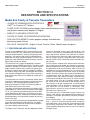
1.1 FEATURES AND APPLICATIONS
The Solu Comp Model Xmt family of transmitters can be
used to measure pH, ORP, conductivity (using either contacting or toroidal sensors), resistivity, oxygen (ppm and
ppb level), free chlorine, total chlorine, monochloramine
and ozone in a variety of process liquids. The Xmt is compatible with most Rosemount Analytical sensors. See the
Specification sections for details.
measures dissolved oxygen (ppm and ppb level), free
chlorine, total chlorine, monochloramine, and ozone in
water and aqueous solutions. The transmitter is compatible with Rosemount Analytical 499A amperometric sensors for oxygen, chlorine, monochloramine, and ozone;
and with Hx438, Bx438, and Gx448 steam-sterilizable oxygen sensors.
The transmitter has a rugged, weatherproof, corrosionresistant enclosure (NEMA 4X and IP65). The panel mount
version fits standard ½ DIN panel cutouts, and its shallow
depth is ideally suited for easy mounting in cabinet-type
enclosures. A panel mount gasket is included to maintain
the weather rating of the panel. Surface/pipe mount enclosure includes self-tapping screws for surface mounting. A
pipe mounting accessory kit is available for mounting to a
2-inch pipe.
For free chlorine measurements, both automatic and manual pH correction are available. pH correction is necessary
because amperometric free chlorine sensors respond only
to hypochlorous acid, not free chlorine, which is the sum of
hypochlorous acid and hypochlorite ion. To measure free
chlorine, most competing instruments require an acidified
sample. Acid lowers the pH and converts hypochlorite ion
to hypochlorous acid. The Model Xmt-P eliminates the
need for messy and expensive sample conditioning by
measuring the sample pH and using it to correct the chlorine sensor signal. If the pH is relatively constant, a fixed
pH correction can be used, and the pH measurement is
not necessary. If the pH is greater than 7.0 and fluctuates
more than about 0.2 units, continuous measurement of pH
and automatic pH correction is necessary. See
Specifications section for recommended pH sensors.
Corrections are valid to pH 9.5.
The transmitter has a two-line 16-character display. Menu
screens for calibrating and registering choices are simple
and intuitive. Plain language prompts guide the user
through the procedures. There are no service codes to
enter before gaining access to menus.
Two digital communication protocols are available: HART
(model option -HT) and FOUNDATION fieldbus (model option
-FF or -FI). Digital communications allow access to AMS
(Asset Management Solutions). Use AMS to set up and
configure the transmitter, read process variables, and troubleshoot problems from a personal computer or host anywhere in the plant.
The seven-button membrane-type keypad allows local programming and calibrating of the transmitter. The HART
Model 375 communicator can also be used for programming and calibrating the transmitter.
The Model Xmt-P Transmitter with the appropriate sensor
The transmitter fully compensates oxygen, ozone, free
chlorine, total chlorine, and monochloramine readings for
changes in membrane permeability caused by temperature changes.
For pH measurements — pH is available with free chlorine
only — the Xmt-P features automatic buffer recognition
and stabilization check. Buffer pH and temperature data
for commonly used buffers are stored in the transmitter.
Glass impedance diagnostics warn the user of an aging or
failed pH sensor.
1
MODEL XMT-P pH/ORP
SECTION 1.0
DESCRIPTION AND SPECIFICATIONS
1.2 SPECIFICATIONS
1.2.1 GENERAL SPECIFICATIONS
Case: ABS (panel mount), polycarbonate (pipe/wall mount);
NEMA 4X/CSA 4 (IP65)
Dimensions
Panel (code -10): 6.10 x 6.10 x 3.72 in. (155 x 155 x
94.5 mm)
Surface/Pipe (code -11): 6.23 x 6.23 x 3.23 in. (158
x 158 x 82 mm); see page 15 for dimensions of pipe
mounting bracket.
Conduit openings: Accepts PG13.5 or 1/2 in. conduit fittings
Ambient Temperature: 32 to 122°F (0 to 50°C). Some
degradation of display above 50°C.
Storage Temperature: -4 to 158°F (-20 to 70°C)
DIGITAL COMMUNICATIONS:
Relative Humidity: 10 to 90% (non-condensing)
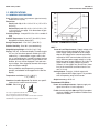
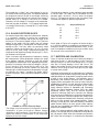
HART —
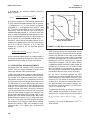
Power & Load Requirements: Supply voltage at the
transmitter terminals should be at least 12 Vdc.
Power supply voltage should cover the voltage
drop on the cable plus the external load resistor
required for HART communications (250 Ω minimum). Minimum power supply voltage is 12 Vdc.
Maximum power supply voltage is 42.4 Vdc. The
graph shows the supply voltage required to
maintain 12 Vdc (upper line) and 30 Vdc (lower
line) at the transmitter terminals when the current is 22 mA.
Weight/Shipping Weight: 2 lb/3 lb (1 kg/1.5 kg)
Display: Two line, 16-character display. Character height:
4.8 mm; first line shows process variable (pH, ORP,
conductivity, % concentration, oxygen, ozone, chlorine, or monochloramine), second line shows process
temperature and output current. For pH/chlorine combination, pH may also be displayed. Fault and warning messages, when triggered, alternate with temperature and output readings.
During calibration and programming, messages,
prompts, and editable values appear on the two-line
display.
Temperature resolution: 0.1°C (≤99.9°C);
1°C (≥100°C)
Hazardous Location Approval: For details, see specifications for the measurement of interest.
Output accuracy: ±0.05 mA
FOUNDATION FIELDBUS —
Power & Load Requirements: A power supply voltage of 9-32 Vdc at 13 mA is required.
RFI/EMI: EN-61326
Sira MC070113/00
Solu Comp is a registered trademark of Rosemount Analytical.
Xmt is a trademark of Rosemount Analytical.
HART is a registered trademark of the HART Communication Foundation.
FOUNDATION is a registered trademark of Fieldbus Foundation.
2
Analog Output: Two-wire, 4-20 mA output with
superimposed HART digital signal. Fully scalable
over the operating range of the sensor.
Fieldbus Intrinsically Safe COncept/FISCO-compliant
versions of Model Xmt Foundation Fieldbus transmitters are available.
MODEL XMT-P pH/ORP
SECTION 1.0
DESCRIPTION AND SPECIFICATIONS
1.2.2 FUNCTIONAL SPECIFICATIONS
pH Range: 0 to 14
ORP Range: -1400 to +1400mV
Calibrations/standardization: The automatic buffer
recognition uses stored buffer values and their temperature curves for the most common buffer standards
available worldwide. The transmitter also performs a
stabilization check on the sensor in each buffer.
A manual two-point calibration is made by immersing
the sensor in two different buffer solutions and entering
the pH values. The microprocessor automatically calculates the slope which is used for self-diagnostics. An
error message will be displayed if the pH sensor is
faulty. This slope can be read on the display and/or
manually adjusted if desired.
An on-line one-point process standardization is accomplished by entering the pH or ORP value of a grab
sample.
Preamplifier Location: A preamplifier must be used to
convert the high impedance pH electrode signal to a low
impedance signal for transmitter use. The integral preamplifier of the Model Xmt-P may be used when the
sensor to transmitter distance is less than 15 ft (4.5 m).
Locate the preamplifier in the sensor or junction box for
longer distances.
Automatic Temperature Compensation: External 3-wire
Pt100 RTD or Pt1000 RTD located in the sensor, compensates the pH reading for temperature fluctuations.
Compensation covers the range -15 to 130°C (5 to 270°F).
Manual temperature compensation is also selectable.
Accuracy: ± 1.4 mV @ 25°C ± 0.01 pH
Repeatability: ± 1 mV @ 25°C ± 0.01 pH
Diagnostics: The internal diagnostics can detect:
Calibration Error
Sensor Failure
High Temperature Warning CPU Failure
Low Temperature Warning
Input Warning
ROM Failure
Glass Warning
Glass Failure
Reference Warning
Reference Failure
Once one of the above is diagnosed, the display will
show a message describing the problem.
DIGITAL COMMUNICATIONS:
HART (pH): PV assigned to pH. SV, TV, and 4V
assignable to pH, temperature, mV, glass impedance, reference impedance, or RTD resistance.
HART (ORP): PV assigned to ORP. SV, TV, and 4V
assignable to ORP, temperature, reference impedance, or RTD resistance.
Fieldbus (pH): Four AI blocks assigned to pH, temperature, reference impedance, and glass impedance.
Fieldbus (ORP): Three AI blocks assigned to ORP,
temperature, and reference impedance.
Fieldbus (pH and ORP): Execution time 75 msec.
One PID block; execution time 150 msec. Device
type 4085. Device revision 1. Certified to ITK 4.5.
SENSOR COMPATIBILITY CHART
pH/ORP SENSOR
320B
330B
320HP-58
328A
370
371
372
381 pHE-31-41-52
381+
385-08-53
385+
389-02-54 / 389VP-54
396-54-62 / 396VP
396P-55 / 396PVP-55
396R / 396RVP-54
397-54-62
398-54-62 / 398VP-54
398R-54-62 / 398RVP-54
399-09-62 / 399VP-09
399-10 / 399-14
399-33
Hx338
Hx348
TF396
DIAGNOSTIC CAPABILITY
Glass and Reference
Glass and Reference
Glass only
Glass only
Glass only
Glass only
Glass only
Glass only
Glass and Reference
Glass only
Glass and Reference
Glass only
Glass only
Glass and Reference
Glass and Reference
Glass only
Glass only
Glass and Reference
Glass only
Glass only
none
Glass only
Glass only
none
3
MODEL XMT-P pH/ORP
SECTION 1.0
DESCRIPTION AND SPECIFICATIONS
1.3 HAZARDOUS LOCATION APPROVALS
Intrinsic Safety:
Class I, II, III, Div. 1
Groups A-G
T4 Tamb = 50°C
Class I, II, III, Div. 1
Groups A-G
T4 Tamb = 50°C
ATEX
1180 II 1 G
Baseefa04ATEX0213X
EEx ia IIC T4
Tamb = 0°C to 50°C
Non-Incendive:
Class I, Div. 2, Groups A-D
Dust Ignition Proof
Class II & III, Div. 1, Groups E-G
NEMA 4/4X Enclosure
Class I, Div. 2, Groups A-D
Dust Ignition Proof
Class II & III, Div. 1, Groups E-G
NEMA 4/4X Enclosure
T4 Tamb = 50°C
4
MODEL XMT-P pH/ORP
SECTION 1.0
DESCRIPTION AND SPECIFICATIONS
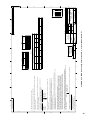
Language
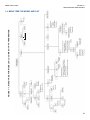
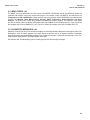
FIGURE 1-1. MENU TREE FOR MODEL SOLU COMP Xmt-P-HT TRANSMITTER
1.4 MENU TREE FOR MODEL XMT-P-HT
5
MODEL XMT-P pH/ORP
SECTION 1.0
DESCRIPTION AND SPECIFICATIONS
6
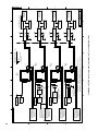
Language
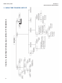
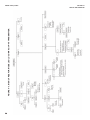
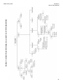
FIGURE 1-2. MENU TREE FOR MODEL SOLU COMP Xmt-P-FF TRANSMITTER
1.5 MENU TREE FOR MODEL XMT-P-FF
MODEL XMT-P pH/ORP
SECTION 1.0
DESCRIPTION AND SPECIFICATIONS
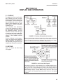
1.6 HART COMMUNICATIONS
1.6.1 OVERVIEW OF HART COMMUNICATION
HART (highway addressable remote transducer) is a digital communication system in which two frequencies are superimposed on the 4 to 20 mA output signal from the transmitter. A 1200 Hz sine wave represents the digit 1, and a 2400 Hz
sine wave represents the digit 0. Because the average value of a sine wave is zero, the digital signal adds no dc component to the analog signal. HART permits digital communication while retaining the analog signal for process control.
The HART protocol, originally developed by Fisher-Rosemount, is now overseen by the independent HART
Communication Foundation. The Foundation ensures that all HART devices can communicate with one another. For more
information about HART communications, call the HART Communication Foundation at (512) 794-0369. The internet
address is http://www.hartcomm.org.
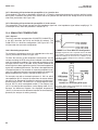
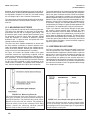
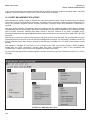
1.6.2 HART INTERFACE DEVICES
The Model 375 HART Communicator is a hand-held device that provides a common link to all HART SMART instruments and allows access to AMS (Asset Management Solutions). Use the HART communicator to set up and control the
Xmt-P-HT and to read measured variables. Press ON to display the on-line menu. All setup menus are available through
this menu.
HART communicators allow the user to view measurement data (pH, ORP and temperature), program the transmitter, and
download information from the transmitter for transfer to a computer for analysis. Downloaded information can also be sent
to another HART transmitter. Either a hand-held communicator, such as the Rosemount Model 375, or a computer can be
used. HART interface devices operate from any wiring termination point in the 4 - 20 mA loop. A minimum load of 250 ohms
must be present between the transmitter and the power supply. See Figure 1-4.
If your communicator does not recognize the Model XMT pH/ORP transmitter, the device description library may need
updating. Call the manufacturer of your HART communication device for updates.
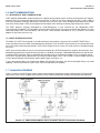
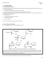
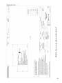
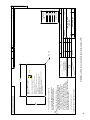
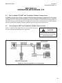
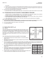
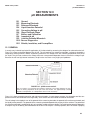
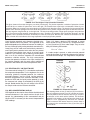
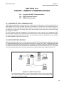
1.7 FOUNDATION FIELDBUS
Figure 1-3 shows a Xmt-P-FF being used to measure and control pH and chlorine levels in drinking water. The figure also
shows three ways in which Fieldbus communication can be used to read process variables and configure the transmitter.
Xmt-P-FF
FIGURE 1-3. CONFIGURING MODEL XMT-P TRANSMITTER WITH FOUNDATION FIELDBUS
7
MODEL XMT-P pH/ORP
SECTION 1.0
DESCRIPTION AND SPECIFICATIONS
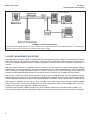
Model Xmt-P
FIGURE 1-4. HART Communicators.
Both the Rosemount Model 375 (or 275) and a computer can be used to communicate with a HART transmitter. The 250 ohm load
(minimum) must be present between the transmitter and the power supply.
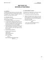
1.8 ASSET MANAGEMENT SOLUTIONS
Asset Management Solutions (AMS) is software that helps plant personnel better monitor the performance of analytical
instruments, pressure and temperature transmitters, and control valves. Continuous monitoring means maintenance personnel can anticipate equipment failures and plan preventative measures before costly breakdown maintenance is
required.
AMS uses remote monitoring. The operator, sitting at a computer, can view measurement data, change program settings,
read diagnostic and warning messages, and retrieve historical data from any HART-compatible device, including the Model
XMT-P transmitter. Although AMS allows access to the basic functions of any HART compatible device, Rosemount
Analytical has developed additional software for that allows access to all features of the Model XMT-P transmitter.
AMS can play a central role in plant quality assurance and quality control. Using AMS Audit Trail, plant operators can track
calibration frequency and results as well as warnings and diagnostic messages. The information is available to Audit Trail
whether calibrations were done using the infrared remote controller, the Model 375 HART communicator, or AMS software.
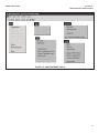
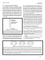
AMS operates in Windows 95. See Figure 1-5 for a sample screen. AMS communicates through a HART-compatible
modem with any HART transmitters, including those from other manufacturers. AMS is also compatible with FOUNDATION™
Fieldbus, which allows future upgrades to Fieldbus instruments.
Rosemount Analytical AMS windows provide access to all transmitter measurement and configuration variables. The
user can read raw data, final data, and program settings and can reconfigure the transmitter from anywhere in the plant.
8
MODEL XMT-P pH/ORP
SECTION 1.0
DESCRIPTION AND SPECIFICATIONS
FIGURE 1-5. AMS MAIN MENU TOOLS
9
MODEL XMT-P pH/ORP
SECTION 1.0
DESCRIPTION AND SPECIFICATIONS
1.9 ORDERING INFORMATION
The Solu Comp Model Xmt Two-Wire Transmitter is intended for the determination of pH, ORP, or Redox.
MODEL
Xmt
SMART TWO-WIRE MICROPROCESSOR TRANSMITTER
CODE
P
REQUIRED SELECTION
pH/ORP
CODE
HT
FF
FI
REQUIRED SELECTION
Analog 4-20 mA output with superimposed HART digital signal
Foundation fieldbus digital output
Foundation fieldbus digital output with FISCO
CODE
10
11
REQUIRED SELECTION
Panel mounting enclosure
Pipe/Surface mounting enclosure (pipe mounting requires accessory kit PN 23820-00)
CODE
60
67
69
73
AGENCY APPROVALS
No approval
FM approved intrinsically safe and non-incendive (when used with appropriate sensor and safety barrier)
CSA approved intrinsically safe and non-incendive (when used with appropriate sensor and safety barrier)
ATEX approved intrinsically safe (when used with appropriate sensor and safety barrier)
Xmt-P-HT-10-67
EXAMPLE
1.10 ACCESSORIES
POWER SUPPLY: Use the Model 515 Power Supply to provide dc loop power to the transmitter. The Model 515 provides two isolated sources at 24Vdc and 200 mA each. For more information refer to product data sheet 71-515.
ALARM MODULE: The Model 230A alarm Module receives the 4-20 mA signal from the Xmt-P-HT transmitter and activates two alarm relays. High/high, low/low, and high/low are available. Hysteresis (deadband) is also adjustable. For
more information, refer to product data sheet 71-230A.
HART COMMUNICATOR: The Model 375 HART communicator allows the user to view measurement values as well as
to program and configure the transmitter. The Model 375 attaches to any wiring terminal across the output loop. A
minimum 250 Ω load must be between the power supply and transmitter. Order the Model 375 communicator from
Emerson Process Management. Call (800) 999-9307.
ACCESSORIES
MODEL/PN
515
23820-00
9240048-00
23554-00
10
DESCRIPTION
DC loop power supply (see product data sheet 71-515)
2-in. pipe mounting kit
Stainless steel tag, specify marking
Gland fittings PG 13.5, 5 per package
MODEL XMT-P pH/ORP
SECTION 2.0
INSTALLATION
SECTION 2.0
INSTALLATION
2.1
2.2
2.3
Unpacking and Inspection
Pre-Installation Set Up
Installation
2.1 UNPACKING AND INSPECTION
Inspect the shipping container. If it is damaged, contact the shipper immediately for instructions. Save the box. If there is
no apparent damage, remove the transmitter. Be sure all items shown on the packing list are present. If items are missing, immediately notify Rosemount Analytical.
Save the shipping container and packaging. They can be reused if it is later necessary to return the transmitter to the factory.
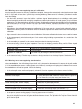
2.2 PRE-INSTALLATION SETUP
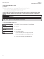
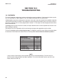
2.2.1 Temperature Element
The Model XMT-P pH/ORP transmitter is compatible with sensors having Pt 100 and Pt 1000. Sensors from other manufacturers may have a Pt 1000 RTD. For Rosemount Analytical sensors, the type of temperature element in the sensor is
printed on the tag attached to the sensor cable. For the majority of sensors manufactured by Rosemount Analytical, the
RTD IN lead is red and the RTD RTN lead is white. The Model 328A sensor has no RTD. The Model 320HP system has
a readily identifiable separate temperature element. Resistance at room temperature for common RTDs is given in the
table.
If the resistance is...
about 110 ohms
about 1100 ohms
the temperature element is a
Pt 100 RTD
Pt 1000 RTD
2.2.2 Reference Electrode Impedance
The standard silver-silver chloride reference electrode used in most industrial and laboratory pH electrodes is low impedance. EVERY pH and ORP sensor manufactured by Rosemount Analytical has a low impedance reference. Certain specialized applications require a high impedance reference electrode. The transmitter must be re-programmed to recognize
the high impedance reference.
11
MODEL XMT-P pH/ORP
SECTION 2.0
INSTALLATION
2.2.3 Preamplifier Location
pH sensors produce a high impedance voltage signal that must be preamplified before use. The signal can be preamplified before it reaches the transmitter or it can be preamplified in the transmitter. To work properly, the transmitter must know
where preamplification occurs. Although ORP sensors produce a low impedance signal, the voltage from an ORP sensor
is amplified the same way as a pH signal.
If the sensor is wired to the transmitter through a junction box, the preamplifier is ALWAYS in either the junction box or the
sensor. Junction boxes can be attached to the sensor or installed some distance away. If the junction box is not attached
to the sensor, it is called a remote junction box. In most junction boxes used with the Model XMT-P pH/ORP, a flat, black
plastic box attached to the same circuit board as the terminal strips houses the preamplifier. The preamplifier housing in
the 381+ sensor is crescent shaped.
If the sensor is wired directly to the transmitter, the preamplifier can be in the sensor or in the transmitter. If the sensor
cable has a GREEN wire, the preamplifier is in the sensor. If there is no green wire, the sensor cable will contain a coaxial cable. A coaxial cable is an insulated wire surrounded by a braided metal shield. Depending on the sensor model, the
coaxial cable terminates in either a BNC connector or in a separate ORANGE wire and CLEAR shield.
12
MODEL XMT-P pH/ORP
SECTION 2.0
INSTALLATION
2.3 INSTALLATION
1. Although the transmitter is suitable for outdoor use,
do not install it in direct sunlight or in areas of extreme
temperatures.
2. Install the transmitter in an area where vibrations and
electromagnetic and radio frequency interference are
minimized or absent.
3. Keep the transmitter and sensor wiring at least one
foot from high voltage conductors. Be sure there is
easy access to the transmitter.
4. The transmitter is suitable for panel (Figure 2-3), pipe
(Figure 2-4), or surface (Figure 2-5) mounting.
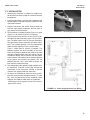
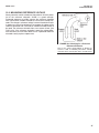
FIGURE 2-1. Removing the Knockouts
5. The transmitter case has two 1/2-inch (PG13.5) conduit openings and either three or four 1/2-inch knockouts. The panel mount Xmt-P-HT has four knockouts.
The pipe/surface mount transmitter has three knockouts*. One conduit opening is for the power/output
cable; the other opening is for the sensor cable.
Figure 1 shows how to remove a knockout. The
knockout grooves are on the outside of the case.
Place the screwdriver blade on the inside of the case
and align it approximately along the groove. Rap the
screwdriver sharply with a hammer until the groove
cracks. Move the screwdriver to an uncracked portion
of the groove and continue the process until the
knockout falls out. Use a small knife to remove the
flash from the inside of the hole.
6. Use weathertight cable glands to keep moisture out to
the transmitter. If conduit is used, plug and seal the
connections at the transmitter housing to prevent
moisture from getting inside the instrument.
7. To reduce the likelihood of stress on wiring connections, do not remove the hinged front panel (-11 models) from the base during wiring installation. Allow
sufficient wire leads to avoid stress on conductors.
*NEMA plug may be supplied instead of knockout for
pipe/surface version.
FIGURE 2-2. Power Supply/Current Loop Wiring
13
MODEL XMT-P pH/ORP
SECTION 2.0
INSTALLATION
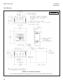
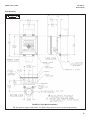
Panel Mounting.
MILLIMETER
INCH
FIGURE 2-3. Panel Mount Installation
Access to the wiring terminals is through the rear cover. Four screws hold the cover in place.
14
MODEL XMT-P pH/ORP
SECTION 2.0
INSTALLATION
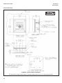
Pipe Mounting.
MILLIMETER
INCH
FIGURE 2-4. Pipe Mount Installation
The front panel is hinged at the bottom. The panel swings down for access to the wiring terminals.
15
MODEL XMT-P pH/ORP
SECTION 2.0
INSTALLATION
Surface Mounting.
MILLIMETER
INCH
FIGURE 2-5. Surface Mount Installation
The front panel is hinged at the bottom. The panel swings down for access to the wiring terminals.
16
MODEL XMT-P pH/ORP
SECTION 3.0
WIRING
SECTION 3.0
WIRING
3.1
POWER SUPPLY/CURRENT LOOP —
MODEL XMT-P-HT
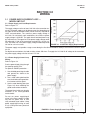
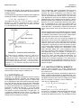
3.1.1 Power Supply and Load Requirements.
Refer to Figure 3-1.
The supply voltage must be at least 12.0 Vdc at the transmitter terminals. The power supply must be able to cover the voltage drop on
the cable as well as the load resistor (250 Ω minimum) required for
HART communications. The maximum power supply voltage is
42.0 Vdc. For intrinsically safe installations, the maximum power
supply voltage is 30.0 Vdc. The graph shows load and power supply requirements. The upper line is the power supply voltage needed to provide 12 Vdc at the transmitter terminals for a 22 mA current. The lower line is the power supply voltage needed to provide
30 Vdc for a 22 mA current.
FIGURE 3-1. Load/Power Supply Requirements
The power supply must provide a surge current during the first 80 milliseconds of startup. The maximum current is about
24 mA.
For digital communications, the load must be at least 250 ohms. To supply the 12.0 Vdc lift off voltage at the transmitter,
the power supply voltage must be at least 17.5 Vdc.
3.1.2 Power Supply-Current Loop
Wiring.
Refer to Figure 3-2.
Run the power/signal wiring through
the opening nearest TB-2.
For optimum EMI/RFI protection . . .
1. Use shielded power/signal cable
and ground the shield at the
power supply.
2. Use a metal cable gland and be
sure the shield makes good electrical contact with the gland.
3. Use the metal backing plate (see
Figure 2-6) when attaching the
gland to transmitter enclosure.
The power/signal cable can also be
enclosed in an earth-grounded
metal conduit.
Do not run power supply/signal
wiring in the same conduit or cable
tray with AC power lines or with
relay actuated signal cables. Keep
power supply/signal wiring at least
6 ft (2 m) away from heavy electrical
equipment.
FIGURE3-2. Power Supply/Current Loop Wiring
17
MODEL XMT-P pH/ORP
3.2
SECTION 3.0
WIRING
POWER SUPPLY WIRING FOR
MODEL XMT-P-FF
3.2.1 Power Supply Wiring. Refer to Figure 3-3 and
Figure 3-4.
Run the power/signal wiring through the opening nearest
TB2. Use shielded cable and ground the shield at the
power supply. To ground the transmitter, attach the shield
to TB2-3.
NOTE
For optimum EMI/RFI immunity, the power supply/output cable should be shielded and enclosed
in an earth-grounded metal conduit.
Do not run power supply/signal wiring in the same conduit
or cable tray with AC power lines or with relay actuated
signal cables. Keep power supply/signal wiring at least
6 ft (2 m) away from heavy electrical equipment.
Panel Mount
XMT-P pH/ORP
Transmitter
FIGURE 3-3. Typical Fieldbus Network Electrical
Wiring Configuration
Pipe/Surface Mount
FIGURE 3-4. Loop Power and Sensor Wiring
18
XMT-P pH/ORP
Transmitter
MODEL XMT-P pH/ORP
SECTION 3.0
WIRING
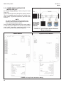
3.3 SENSOR WIRING
3.3.1 Sensor Wiring Information
pH and ORP sensors manufactured by Rosemount Analytical can be wired to the Model XMT-P transmitter in three ways:
1. directly to the transmitter,
2. to a sensor-mounted junction box and then to the transmitter,
3. to a remote junction box and then from the remote junction box to the transmitter.
The pH (or ORP) signal can also be preamplified in one of four places. See Section 7.4.3 for set-up. The transmitter is factory configured with a preamplifier.
1. in the sensor (a, d),
2. in a junction box mounted on the sensor (c),
3. in a remote junction box (e).
4. at the transmitter (b).
NOTE: For 22K NTC RTDs, wire leads to TB1-1 and TB1-3.
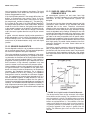
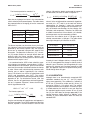
3.3.2 General Wiring Configurations
Figure 3-5 illustrates the various wiring arrangements for Xmt-P.
FIGURE 3-5. Wiring and Preamplifier Configurations for pH and ORP Sensors.
The asterisk identifies the location of the preamplifier. In (a) and (b) the sensor is wired directly to the transmitter. The signal is amplified at the sensor (a) or at the transmitter (b). In (c) the sensor is wired through a sensor-mounted junction box to the transmitter.
The preamplifier is in the sensor-mounted junction box. In (d) and (e) the sensor is wired through a remote junction box to the transmitter. The preamplifier is located in the sensor (d) or the junction box (e).
Refer to the Instruction Sheet provided with each sensor for specific wiring instructions.
19
MODEL XMT-P pH/ORP
SECTION 4.0
INTRINSICALLY SAFE INSTALLATION
SECTION 4.0
INTRINSICALLY SAFE INSTALLATION
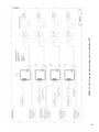
INTRINSICALLY SAFE INSTALLATIONS FOR MODEL XMT-P-HT
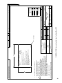
For CSA Instrinsically Safe Installation, see Figure 4-4.
For ATEX Instrinsically Safe Label, see Figure 4-5.
For ATEX Instrinsically Safe Installation, see Figure 4-6.
FIGURE 4-1. FM Intrinsically Safe Label for Model Xmt-P-HT
For FM Intrinsically Safe Label, see Figure 4-1.
For FM Intrinsically Safe Installation, see Figure 4-2.
For CSA Instrinsically Safe Label, see Figure 4-3.
20
21
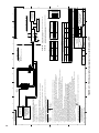
FIGURE 4-2. FM Intrinsically Safe Installation (1 of 2) for Model Xmt-P-HT
22
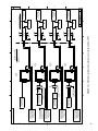
FIGURE 4-3. FM Intrinsically Safe Installation (2 of 2) for Model Xmt-P-HT
23
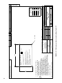
FIGURE 4-4. CSA Intrinsically Safe Label for Model Xmt-P-HT
24
FIGURE 4-5. CSA Intrinsically Safe Installation (1 of 2) for Model Xmt-P-HT
25
FIGURE 4-6. CSA Intrinsically Safe Installation (2 of 2) for Model Xmt-P-HT
26
FIGURE 4-7. ATEX Intrinsically Safe Label for Model Xmt-P-HT
27
FIGURE 4-8. ATEX Intrinsically Safe Installation (1 of 2) for Model Xmt-P-HT
28
FIGURE 4-9. ATEX Intrinsically Safe Installation (2 of 2) for Model Xmt-P-HT
R
Analytical
FM
MATERIAL: 3M SCOTCHCAL #3650-10
(WHITE VINYL FACESTOCK) OR POLYESTER,
(.002 REFERENCE THICKNESS CLEAR MATTE
MYLAR OVERLAMINATE, .002-.005 FINISH
THICKNESS. PRESSURE SENSITIVE ADHESIVE,
FARSIDE AND SPLIT LINER) OR (INTERMEC
PN L7211210, 2 MIL GLOSS WHITE POLYESTER WITH
PRESSURE SENSITIVE ACRYLIC ADHESIVE.
NOMENCLATURE TO BE PRINTED USING INTERMEC
SUPER PREMIUM BLACK THERMAL TRANSFER RIBBON)
SEE BLANK LABEL PN 9241406-01.
ARTWORK IS SHEET 2 OF 2.
2
1.
FINISH
ANGLES
TOLERANCES
+ 1/2
-
2
DIMENSIONS ARE IN INCHES
REMOVE BURRS & SHARP EDGES .020 MAX
MACHINED FILLET RADII .020 MAX
NOMINAL SURFACE FINISH 125
+ .030
+- .010
MATERIAL
.XXX
.XX
UNLESS OTHERWISE SPECIFIED
9241564-00/A
10-6-04
RELEASE DATE
J. FLOCK
J. FLOCK
B. JOHNSON
THIS DWG CONVERTED TO
SOLID EDGE
PROJECT
ENGR APVD
LTR
PART NO
A
REV
APPROVALS
CHECKED
DRAWN
ITEM
4X R .060
9042
ECO NO
ECO
10 /6 /04
DATE
FM
REV
REV
REV
REV
REV
REV
A
SHEET 1 OF
CHK
2
06-01
REV
A
QTY
Emerson Process Management,
Rosemount Analytical Division
2400 Barranca Pkwy
Irvine, CA 92606
REVISIONS NOT PERMITTED
W/O AGENCY APPROVAL
9241564-00
DWG NO
SCALE 2:1
B
SIZE
BY
THIS DOCUMENT IS
CERTIFIED BY
LABEL, I.S. FM
XMT-P-FF
DESCRIPTION
Emerson
TITLE
REVISIONS
DESCRIPTION
BILL OF MATERIAL
10 /6 /04
10/ 1/03
DATE
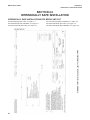
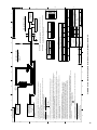
FIGURE 4-10. FM Intrinsically Safe Label for Model Xmt-P-FF
ALL ALPHA AND NUMERIC CHARACTERS
ON LABEL TO BE BLACK HELVETICA
MEDIUM. BACKGROUND TO BE WHITE.
3.
NOTES: UNLESS OTHERWISE SPECIFIED
NO CHANGE WITHOUT FM APPROVAL.
INTRINSICALLY SAFE FOR CLASS I, II & III, DIVISION 1,
GROUPS A, B, C, D, E, F & G
HAZARDOUS AREA WHEN CONNECTED PER DWG. 1400240
T4 Tamb = 50°C
NON-INCENDIVE CLASS I, DIVISION 2 GROUPS A, B, C & D
DUST IGNITION PROOF CLASS II AND III, DIVISION 1,
GROUPS E, F & G
WARNING: COMPONENT SUBSTITUTION MAY IMPAIR INTRINSIC
SAFETY OR SUITABILITY FOR DIVISION 2
NEMA 4/4X ENCLOSURE
SUPPLY 9-32 VDC @ 22 mA
APPROVED
NORMAL OPERATING TEMPERATURE RANGE: 0-50vC
MODEL
XMT-P-FF-67
Rosemount
2.50
4.
1.50
This document contains information proprietary to
Rosemount Analytical, and is not to be made available
to those who may compete with Rosemount Analytical.
B 9241564-00
29
8
MODEL
XMT-P-FF
XMTR
6
1 2 3 4 5 6 7 8 9 10 11 12
5
8
NOTES: UNLESS OTHERWISE SPECIFIED
Voc OR Vt NOT GREATER THAN 30 V
Isc OR It NOT GREATER THAN 200 mA
Pmax NOT GREATER THAN 0.9 W
7
5
9064
ECO NO.
RELEASE DATE
30
375
10-6-04
Vmax IN: Vdc
MODEL NO.
Vmax (Vdc)
30
4
TABLE III
7.97
2.974
0.974
La
(mH)
REV
A
Ci (nF)
0.4
Pmax (W)
1.3
0
Li (mH)
511.59mW
157.17mA
13.03V
FINISH
ANGLES
TOLERANCES
+ 1/2
-
3
DIMENSIONS ARE IN INCHES
REMOVE BURRS & SHARP EDGES .020MAX
MACHINED FILLET RADII .020 MAX
NOMINAL SURFACE FINISH 125
+ .030
+ .010
-
MATERIAL
.XX
.XXX
B. JOHNSON
J. FLOCK
DATE
10/6/04
10/6/04
9/15/04
2
THIS DWG CONVERTED TO
SOLID EDGE
PROJECT
ENGR APVD
CHECKED J. FLOCK
DRAWN
BILL OF MATERIAL
Uniloc
DATE
REV
REV
REV
REV
REV
REV
D
DWG NO.
SCALE NONE
SIZE
1400240
TYPE
A
Rosemount Analytical,
Uniloc Division
2400 Barranca Pkwy
Irvine, CA 92606
32
1
SHEET 1 OF
2
Isc max OUT:uA
REVISIONS NOT PERMITTED
W/O AGENCY APPROVAL
FM
THIS DOCUMENT IS
CERTIFIED BY
SCHEMATIC, INSTALLATION
MOD XMT-P-FF XMTR
(FM APPROVALS)
TITLE
1.9
0.0
DESCRIPTION
Voc max OUT: Vdc
Li (mH)
PART NO.
APPROVALS
0.0
1.0
ITEM
Ci (uF)
Pamx IN: W
UNLESS OTHERWISE SPECIFIED
200
Imax IN:mA
ENTITY PARAMETERS: REMOTE TRANSMITTER INTERFACE
300
Imax (mA)
Po
Io
Uo
MODEL XMT-P-FF
TB1-1 THRU 12
TABLE II
OUTPUT
PARAMETERS
XMT-P-FF ENTITY PARAMETERS
SUPPLY / SIGNAL TERMINALS TB2-1, 2 AND 3
21.69
5.99
0.9645
Ca
(uF)
OUTPUT PARAMETERS
TABLE I
TO PREVENT IGNITION OF FLAMMABLE OR COMBUSTIBLE ATMOSPHERES,
DISCONNECT POWER BEFORE SERVICING.
LOAD
BY
1
UNSPECIFIED
POWER SUPPLY
30 VDC MAX FOR IS
24V TYP
NON-HAZARDOUS AREA
DESCRIPTION
REVISION
WARNING-
XMT-P-FF
MODEL NO.
D
C
A, B
GAS
GROUPS
ECO
SAFETY BARRIER
(SEE NOTES 1 & 9)
LTR
2
SUBSTITUTION OF COMPONENTS MAY IMPAIR INTRINSIC SAFETY OR
SUITABILITY FOR DIVISION 2.
3
WARNING-
IS CLASS I, II, III,
DIVISION 1,
GROUPS A, B, C, D, E, F, G;
HAZARDOUS AREA
4
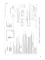
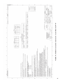
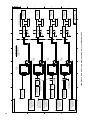
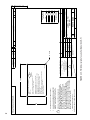
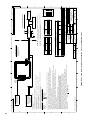
FIGURE 4-11. FM Intrinsically Safe Installation (1 of 2) for Model Xmt-P-FF
6
1. ANY SINGLE SHUNT ZENER DIODE SAFETY BARRIER APPROVED BY FM HAVING THE FOLLOWING OUTPUT PARAMETERS:
SUPPLY/SIGNAL TERMINALS TB2-1, 2 AND 3.
2. THE MODEL XMT-P-FF TRANSMITTER INCLUDES INTEGRAL PREAMPLIFIER CIRCUITRY. AN EXTERNAL PREAMPLIFIER
MAY BE ALSO USED. THE OUTPUT PARAMETERS SPECIFIED IN TABLE II ARE VALID FOR EITHER PREAMPLIFIER.
THE CAPACITANCE AND INDUCTANCE OF THE LOAD CONNECTED TO THE SENSOR TERMINALS MUST NOT EXCEED THE VALUES
SPECIFIED IN TABLE I
WHERE Ca Ci (SENSOR) + Ccable;
La Li (SENSOR) + Lcable.
3. INTRINSICALLY SAFE APPARATUS (MODEL XMT-P-FF, MODEL 375)
AND ASSOCIATED APPARATUS (SAFETY BARRIER) SHALL MEET THE FOLLOWING REQUIREMENTS:
THE VOLTAGE (Vmax) AND CURRENT (Imax) OF THE INTRINSICALLY SAFE APPARATUS MUST BE
EQUAL TO OR GREATER THAN THE VOLTAGE (Voc OR Vt) AND CURRENT (Isc OR It) WHICH CAN BE
DELIVERED BY THE ASSOCIATED APPARATUS (SAFETY BARRIER). IN ADDITION, THE MAXIMUM
UNPROTECTED CAPACITANCE (Ci) AND INDUCTANCE (Li) OF THE INTRINSICALLY SAFE APPARATUS,
INCLUDING INTERCONNECTING WIRING, MUST BE EQUAL OR LESS THAN THE CAPACITANCE (Ca) AND
INDUCTANCE (La) WHICH CAN BE SAFELY CONNECTED TO THE APPARATUS. (REF. TABLES I, II AND III).
4. PREAMPLIFIER TYPE 23546-00, 23538-00 OR 23561-00 MAY BE UTILIZED INSTEAD OF THE MODEL XMT-P-FF
TRANSMITTER INTEGRAL PREAMPLIFIER CIRCUITRY. A WEATHER RESISTANT ENCLOSURE MUST HOUSE THE TYPE
23546-00 REMOTE PREAMPLIFIER.
5. INSTALLATION SHOULD BE IN ACCORDANCE WITH ANSI/ISA RP12.06.01 "INSTALLATION OF INTRINSICALLY SAFE
SYSTEMS FOR HAZARDOUS (CLASSIFIED) LOCATIONS" AND THE NATIONAL ELECTRICAL CODE (ANSI/NFPA 70) SECTIONS 504 AND 505.
6. SENSORS WITHOUT PREAMPS SHALL MEET THE REQUIREMENTS OF SIMPLE APPARATUS AS DEFINED IN ANSI/ISA RP12.6
AND THE NEC, ANSI/NFPA 70. THEY CAN NOT GENERATE NOR STORE MORE THAN 1.5V, 100mA, 25mW OR A PASSIVE
COMPONENT THAT DOES NOT DISSIPATE MORE THAN 1.3W.
7. DUST-TIGHT CONDUIT SEAL MUST BE USED WHEN INSTALLED IN CLASS II AND CLASS III ENVIRONMENTS.
8. RESISTANCE BETWEEN INTRINSICALLY SAFE GROUND AND EARTH GROUND MUST BE LESS THAN 1.0 Ohm.
9. THE INTRINSICALLY SAFE ENTITY CONCEPT ALLOWS INTERCONNECTION OF INTRINSICALLY SAFE DEVICES
WITH ASSOCIATED APPARATUS WHEN THE FOLLOWING IS TRUE:
FIELD DEVICE INPUT
ASSOCIATED APPARATUS OUTPUT
Vmax OR Ui
Voc, Vt OR Uo;
Isc, It OR Io;
Imax OR Ii
Pmax OR Pi
Po;
Ca, Ct OR Co
Ci+ Ccable;
Li+ Lcable.
La, Lt OR Lo
10. ASSOCIATED APPARATUS MANUFACTURER'S INSTALLATION DRAWING MUST BE FOLLOWED
WHEN INSTALLING THIS EQUIPMENT.
11. CONTROL EQUIPMENT CONNECTED TO ASSOCIATED APPARATUS MUST NOT USE OR GENERATE
MORE THAN 250 Vrms OR Vdc.
12. THE ASSOCIATED APPARATUS MUST BE FM APPROVED.
13. NO REVISION TO DRAWING WITHOUT PRIOR
FM APPROVAL.
14. METAL CONDUIT IS NOT REQUIRED BUT IF USED BONDING
BETWEEN CONDUIT IS NOT AUTOMATIC AND MUST BE
PROVIDED AS PART OF THE INSTALLATION.
ROSEMOUNT MODEL 375
FIELD COMMUNICATOR
REMOTE TRANSMITTER
INTERFACE FOR USE IN
CLASS I AREA ONLY
(SEE NOTE 3 AND
TABLE III)
+PH SENSOR
FM APPROVED DEVICE
OR SIMPLE APPARATUS
7
3 2 1
A
B
C
D
30
This document contains information proprietary to
Rosemount Analytical, and is not to be made available
to those who may compete with Rosemount Analytical.
10-96
A
REV
QTY
CHK
A
B
C
D 1400240
8
PREAMP
(NOTE 4)
6
MODEL
XMT-P-FF
XMTR
5
5
3 2 1
MODEL
XMT-P-FF
XMTR
MODEL
XMT-P-FF
XMTR
MODEL
XMT-P-FF
XMTR
4
IS CLASS I, II, III,
DIVISION 1,
GROUPS A, B, C, D, E, F, G;
HAZARDOUS AREA
4
3
3
SAFETY BARRIER
(SEE NOTES 1 & 9)
SAFETY BARRIER
(SEE NOTES 1 & 9)
SAFETY BARRIER
(SEE NOTES 1 & 9)
SAFETY BARRIER
(SEE NOTES 1 & 9)
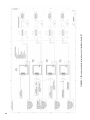
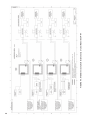
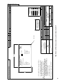
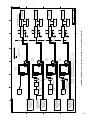
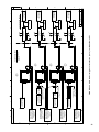
FIGURE 4-12. FM Intrinsically Safe Installation (2 of 2) for Model Xmt-P-FF
RECOMMENDED CABLE
4 WIRES SHIELDED
22 AWG, SEE NOTE 2
TB14
5
7
10
FM APPROVED PREAMP
THAT MEETS REQUIREMENTS
OF NOTE 4
PH SENSOR WITH TC
FM APPROVED DEVICE
OR SIMPLE APPARATUS
+PH SENSOR
FM APPROVED DEVICE
OR SIMPLE APPARATUS
7
PREAMP
(NOTE 4)
FM APPROVED PREAMP
THAT MEETS REQUIREMENTS
OF NOTE 4
+PH SENSOR
FM APPROVED DEVICE
OR SIMPLE APPARATUS
6
3 2 1
ROSEMOUNT MODEL 375
HART COMMUNICATOR
REMOTE TRANSMITTER
INTERFACE FOR USE IN
CLASS I AREA ONLY
(SEE NOTE 3 AND
TABLE III)
ROSEMOUNT MODEL 375
HART COMMUNICATOR
REMOTE TRANSMITTER
INTERFACE FOR USE IN
CLASS I AREA ONLY
(SEE NOTE 3 AND
TABLE III)
ROSEMOUNT MODEL 375
HART COMMUNICATOR
REMOTE TRANSMITTER
INTERFACE FOR USE IN
CLASS I AREA ONLY
(SEE NOTE 3 AND
TABLE III)
RECOMMENDED CABLE
PN 9200273 (UNPREPPED)
PN 23646-01 PREPPED
10 COND, 2 SHIELDS, 24 AWG
SEE NOTE 2
ROSEMOUNT MODEL 375
HART COMMUNICATOR
REMOTE TRANSMITTER
INTERFACE FOR USE IN
CLASS I AREA ONLY
(SEE NOTE 3 AND
TABLE III)
+PH SENSOR
FM APPROVED DEVICE
OR SIMPLE APPARATUS
7
3 2 1
A
B
C
D
8
This document contains information proprietary to
Rosemount Analytical, and is not to be made available
to those who may compete with Rosemount Analytical.
1 2 3 4 5 6 7 8 9 10 11 12
1 2 3 4 5 6 7 8 9 10 11 12
1 2 3 4 5 6 7 8 9 10 11 12
3 2 1
1 2 3 4 5 6 7 8 9 10 11 12
2
DWG NO.
SCALE NONE
SIZE
D
LOAD
LOAD
LOAD
LOAD
1
SHEET 2 OF
UNSPECIFIED
POWER SUPPLY
30 VDC MAX FOR IS
24V TYP
UNSPECIFIED
POWER SUPPLY
30 VDC MAX FOR IS
24V TYP
UNSPECIFIED
POWER SUPPLY
30 VDC MAX FOR IS
24V TYP
1400240
TYPE
1
UNSPECIFIED
POWER SUPPLY
30 VDC MAX FOR IS
24V TYP
UNCLASSIFIED AREA
2
2
06-01
A
REV
A
B
C
D 1400240
31
32
R
Analytical
R
-LR 34186
MATERIAL: 3M SCOTCHCAL #3650-10
(WHITE VINYL FACESTOCK) OR POLYESTER,
(.002 REFERENCE THICKNESS CLEAR MATTE
MYLAR OVERLAMINATE, .002-.005 FINISH
THICKNESS. PRESSURE SENSITIVE ADHESIVE,
FARSIDE AND SPLIT LINER) OR (INTERMEC
PN L7211210, 2 MIL GLOSS WHITE POLYESTER WITH
PRESSURE SENSITIVE ACRYLIC ADHESIVE.
NOMENCLATURE TO BE PRINTED USING INTERMEC
SUPER PREMIUM BLACK THERMAL TRANSFER RIBBON)
SEE BLANK LABEL PN 9241406-01.
ARTWORK IS SHEET 2 OF 2.
2
1.
FINISH
ANGLES
TOLERANCES
+ 1/2
-
2
DIMENSIONS ARE IN INCHES
REMOVE BURRS & SHARP EDGES .020 MAX
MACHINED FILLET RADII .020 MAX
NOMINAL SURFACE FINISH 125
+ .030
+- .010
MATERIAL
.XXX
.XX
UNLESS OTHERWISE SPECIFIED
9241572-00/A
10-6-04
RELEASE DATE
J. FLOCK
J. FLOCK
B. JOHNSON
THIS DWG CONVERTED TO
SOLID EDGE
PROJECT
ENGR APVD
LTR
PART NO
A
REV
APPROVALS
CHECKED
DRAWN
ITEM
4X R .060
9033
ECO NO
ECO
10/6 /04
10/6 /04
9/24/03
DATE
DATE
REV
REV
REV
REV
REV
REV
A
SHEET 1 OF
CHK
2
06-01
REV
A
QTY
Emerson Process Management,
Rosemount Analytical Division
2400 Barranca Pkwy
Irvine, CA 92606
REVISIONS NOT PERMITTED
W/O AGENCY APPROVAL
CSA
9241572-00
DWG NO
SCALE 2:1
B
SIZE
BY
THIS DOCUMENT IS
CERTIFIED BY
LABEL, I.S. CSA
XMT-P-FF
DESCRIPTION
Emerson
TITLE
REVISIONS
DESCRIPTION
BILL OF MATERIAL
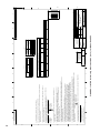
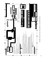
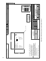
FIGURE 4-13. CSA Intrinsically Safe Label for Model Xmt-P-FF
ALL ALPHA AND NUMERIC CHARACTERS
ON LABEL TO BE BLACK HELVETICA
MEDIUM. BACKGROUND TO BE WHITE.
3.
NOTES: UNLESS OTHERWISE SPECIFIED
NO CHANGE WITHOUT CSA APPROVAL.
INTRINSICALLY SAFE FOR CLASS I, II & III, DIVISION 1,
GROUPS A, B, C, D, E, F & G
HAZARDOUS AREA WHEN CONNECTED PER DWG. 1400256
T4 Tamb = 50°C
NON-INCENDIVE CLASS I, DIVISION 2 GROUPS A, B, C & D
DUST IGNITION PROOF CLASS II AND III, DIVISION 1,
GROUPS E, F & G
WARNING: COMPONENT SUBSTITUTION MAY IMPAIR INTRINSIC
SAFETY OR SUITABILITY FOR DIVISION 2
NEMA 4/4X ENCLOSURE
SUPPLY 9-32 VDC @ 22 mA
NORMAL OPERATING TEMPERATURE RANGE: 0-50vC
MODEL
XMT-P-FF-69
Rosemount
2.50
4.
1.50
This document contains information proprietary to
Rosemount Analytical, and is not to be made available
to those who may compete with Rosemount Analytical.
B 9241572-00
MODEL
XMT-P-FF
XMTR
6
1 2 3 4 5 6 7 8 9 10 11 12
5
8
NOTES: UNLESS OTHERWISE SPECIFIED
Voc OR Vt NOT GREATER THAN 30 V
Isc OR It NOT GREATER THAN 300 mA
Pmax NOT GREATER THAN 1.3 W
7
5
30
375
4
ECO NO.
9047
Vmax IN: Vdc
Vmax (Vdc)
MODEL NO.
RELEASE DATE
TABLE III
7.97
2.974
0.974
La
(mH)
REV
A
Ci (nF)
0.4
Pmax (W)
1.3
Po
Io
Uo
0
Li (mH)
511.59mW
157.17mA
13.03V
MODEL XMT-P-FF
TB1-1 THRU 12
FINISH
+ 1/2
DIMENSIONS ARE IN INCHES
ANGLES
TOLERANCES
3
REMOVE BURRS & SHARP EDGES .020MAX
MACHINED FILLET RADII .020 MAX
NOMINAL SURFACE FINISH 125
+
- .030
+ .010
-
MATERIAL
.XX
.XXX
B. JOHNSON
J. FLOCK
DATE
10/6/04
10/6/04
9/15/04
2
THIS DWG CONVERTED TO
SOLID EDGE
PROJECT
ENGR APVD
CHECKED J. FLOCK
DRAWN
BILL OF MATERIAL
Uniloc
DATE
REV
REV
REV
REV
REV
REV
D
DWG NO.
SCALE NONE
SIZE
1400256
TYPE
A
Rosemount Analytical,
Uniloc Division
2400 Barranca Pkwy
Irvine, CA 92606
32
1
SHEET 1 OF
2
Isc max OUT:uA
REVISIONS NOT PERMITTED
W/O AGENCY APPROVAL
CSA
THIS DOCUMENT IS
CERTIFIED BY
SCHEMATIC, INSTALLATION
MOD XMT-P-FF XMTR
(CSA)
TITLE
1.9
0.0
DESCRIPTION
Voc max OUT: Vdc
Li (mH)
PART NO.
APPROVALS
0.0
1.0
ITEM
Ci (uF)
Pmax IN: W
UNLESS OTHERWISE SPECIFIED
200
Imax IN:mA
ENTITY PARAMETERS: REMOTE TRANSMITTER INTERFACE
300
Imax (mA)
TABLE II
OUTPUT
PARAMETERS
XMT-P-FF ENTITY PARAMETERS
SUPPLY / SIGNAL TERMINALS TB2-1, 2 AND 3
21.69
5.99
0.9645
Ca
(uF)
OUTPUT PARAMETERS
TABLE I
TO PREVENT IGNITION OF FLAMMABLE OR COMBUSTIBLE ATMOSPHERES,
DISCONNECT POWER BEFORE SERVICING.
LOAD
BY
1
UNSPECIFIED
POWER SUPPLY
30 VDC MAX FOR IS
24V TYP
NON-HAZARDOUS AREA
DESCRIPTION
REVISION
WARNING-
30
10-6-04
ECO
SAFETY BARRIER
(SEE NOTES 1 & 9)
LTR
2
SUBSTITUTION OF COMPONENTS MAY IMPAIR INTRINSIC SAFETY OR
SUITABILITY FOR DIVISION 2.
3
WARNING-
XMT-P-FF
MODEL NO.
D
C
A, B
GAS
GROUPS
IS CLASS I, GRPS A-D
CLASS II, GRPS E-G
CLASS III
HAZARDOUS AREA
4
FIGURE 4-14. CSA Intrinsically Safe Installation (1 of 2) for Model Xmt-P-FF
6
1. ANY SINGLE SHUNT ZENER DIODE SAFETY BARRIER APPROVED BY CSA HAVING THE FOLLOWING OUTPUT PARAMETERS:
SUPPLY/SIGNAL TERMINALS TB2-1, 2 AND 3.
2. THE MODEL XMT-P-FF TRANSMITTER INCLUDES INTEGRAL PREAMPLIFIER CIRCUITRY. AN EXTERNAL PREAMPLIFIER
MAY BE ALSO USED. THE OUTPUT PARAMETERS SPECIFIED IN TABLE II ARE VALID FOR EITHER PREAMPLIFIER.
THE CAPACITANCE AND INDUCTANCE OF THE LOAD CONNECTED TO THE SENSOR TERMINALS MUST NOT EXCEED THE VALUES
WHERE Ca
Ci (SENSOR) + Ccable;
SPECIFIED IN TABLE I
La
Li (SENSOR) + Lcable.
3. INTRINSICALLY SAFE APPARATUS (MODEL XMT-P-FF, MODEL 375)
AND ASSOCIATED APPARATUS (SAFETY BARRIER) SHALL MEET THE FOLLOWING REQUIREMENTS:
THE VOLTAGE (Vmax) AND CURRENT (Imax) OF THE INTRINSICALLY SAFE APPARATUS MUST BE
EQUAL TO OR GREATER THAN THE VOLTAGE (Voc OR Vt) AND CURRENT (Isc OR It) WHICH CAN BE
DELIVERED BY THE ASSOCIATED APPARATUS (SAFETY BARRIER). IN ADDITION, THE MAXIMUM
UNPROTECTED CAPACITANCE (Ci) AND INDUCTANCE (Li) OF THE INTRINSICALLY SAFE APPARATUS,
INCLUDING INTERCONNECTING WIRING, MUST BE EQUAL OR LESS THAN THE CAPACITANCE (Ca) AND
INDUCTANCE (La) WHICH CAN BE SAFELY CONNECTED TO THE APPARATUS. (REF. TABLES I, II AND III).
4. PREAMPLIFIER TYPE 23546-00, 23538-00 OR 23561-00 MAY BE UTILIZED INSTEAD OF THE MODEL XMT-P-FF
TRANSMITTER INTEGRAL PREAMPLIFIER CIRCUITRY. A WEATHER RESISTANT ENCLOSURE MUST HOUSE THE TYPE
23546-00 REMOTE PREAMPLIFIER.
5. INSTALLATION SHOULD BE IN ACCORDANCE WITH ANSI/ISA RP12.06.01 "INSTALLATION OF INTRINSICALLY SAFE
SYSTEMS FOR HAZARDOUS (CLASSIFIED) LOCATIONS" AND THE CANADIAN ELECTRICAL CODE, CSA C22.1, PART 1, APPENDIX F.
6. SENSORS WITHOUT PREAMPS SHALL MEET THE REQUIREMENTS OF SIMPLE APPARATUS AS DEFINED IN ANSI/ISA RP12.6
AND THE NEC, ANSI/NFPA 70. THEY CAN NOT GENERATE NOR STORE MORE THAN 1.5V, 100mA, 25mW OR A PASSIVE
COMPONENT THAT DOES NOT DISSIPATE MORE THAN 1.3W.
7. DUST-TIGHT CONDUIT SEAL MUST BE USED WHEN INSTALLED IN CLASS II AND CLASS III ENVIRONMENTS.
8. RESISTANCE BETWEEN INTRINSICALLY SAFE GROUND AND EARTH GROUND MUST BE LESS THAN 1.0 Ohm.
9. THE INTRINSICALLY SAFE ENTITY CONCEPT ALLOWS INTERCONNECTION OF INTRINSICALLY SAFE DEVICES
WITH ASSOCIATED APPARATUS WHEN THE FOLLOWING IS TRUE:
FIELD DEVICE INPUT
ASSOCIATED APPARATUS OUTPUT
Vmax OR Ui
Voc, Vt OR Uo;
Imax OR Ii
Isc, It OR lo;
Pmax OR Pi
Po;
Ci+ Ccable;
Ca, Ct OR Co
La, Lt OR Lo
Li+ Lcable.
10. ASSOCIATED APPARATUS MANUFACTURER'S INSTALLATION DRAWING MUST BE FOLLOWED
WHEN INSTALLING THIS EQUIPMENT.
11. CONTROL EQUIPMENT CONNECTED TO ASSOCIATED APPARATUS MUST NOT USE OR GENERATE
MORE THAN 250 Vrms OR Vdc.
12. THE ASSOCIATED APPARATUS MUST BE CSA APPROVED.
13. NO REVISION TO DRAWING WITHOUT PRIOR
CSA APPROVAL.
ROSEMOUNT MODEL 375
FIELD COMMUNICATOR
REMOTE TRANSMITTER
INTERFACE FOR USE IN
CLASS I AREA ONLY
(SEE NOTE 3 AND
TABLE III)
+PH SENSOR
CSA APPROVED DEVICE
OR SIMPLE APPARATUS
7
3 2 1
A
B
C
D
8
This document contains information proprietary to
Rosemount Analytical, and is not to be made available
to those who may compete with Rosemount Analytical.
10-96
A
REV
QTY
CHK
A
B
C
D 1400256
33
8
PREAMP
(NOTE 4)
6
MODEL
XMT-P-FF
XMTR
5
5
3 2 1
MODEL
XMT-P-FF
XMTR
MODEL
XMT-P-FF
XMTR
MODEL
XMT-P-FF
XMTR
4
IS CLASS I, GRPS A-D
CLASS II, GRPS E-G
CLASS III
HAZARDOUS AREA
4
3
3
SAFETY BARRIER
(SEE NOTES 1 & 9)
SAFETY BARRIER
(SEE NOTES 1 & 9)
SAFETY BARRIER
(SEE NOTES 1 & 9)
SAFETY BARRIER
(SEE NOTES 1 & 9)
FIGURE 4-15. CSA Intrinsically Safe Installation (2 of 2) for Model Xmt-P-FF
RECOMMENDED CABLE
4 WIRES SHIELDED
22 AWG, SEE NOTE 2
PH SENSOR WITH TC
CSA APPROVED DEVICE
OR SIMPLE APPARATUS
TB14
5
7
10
CSA APPROVED PREAMP
THAT MEETS REQUIREMENTS
OF NOTE 4
+PH SENSOR
CSA APPROVED DEVICE
OR SIMPLE APPARATUS
7
PREAMP
(NOTE 4)
CSA APPROVED PREAMP
THAT MEETS REQUIREMENTS
OF NOTE 4
+PH SENSOR
CSA APPROVED DEVICE
OR SIMPLE APPARATUS
6
3 2 1
ROSEMOUNT MODEL 375
HART COMMUNICATOR
REMOTE TRANSMITTER
INTERFACE FOR USE IN
CLASS I AREA ONLY
(SEE NOTE 3 AND
TABLE III)
ROSEMOUNT MODEL 375
HART COMMUNICATOR
REMOTE TRANSMITTER
INTERFACE FOR USE IN
CLASS I AREA ONLY
(SEE NOTE 3 AND
TABLE III)
ROSEMOUNT MODEL 375
HART COMMUNICATOR
REMOTE TRANSMITTER
INTERFACE FOR USE IN
CLASS I AREA ONLY
(SEE NOTE 3 AND
TABLE III)
RECOMMENDED CABLE
PN 9200273 (UNPREPPED)
PN 23646-01 PREPPED
10 COND, 2 SHIELDS, 24 AWG
SEE NOTE 2
ROSEMOUNT MODEL 375
HART COMMUNICATOR
REMOTE TRANSMITTER
INTERFACE FOR USE IN
CLASS I AREA ONLY
(SEE NOTE 3 AND
TABLE III)
+PH SENSOR
CSA APPROVED DEVICE
OR SIMPLE APPARATUS
7
3 2 1
A
B
C
D
8
This document contains information proprietary to
Rosemount Analytical, and is not to be made available
to those who may compete with Rosemount Analytical.
1 2 3 4 5 6 7 8 9 10 11 12
1 2 3 4 5 6 7 8 9 10 11 12
34
1 2 3 4 5 6 7 8 9 10 11 12
3 2 1
1 2 3 4 5 6 7 8 9 10 11 12
2
DWG NO.
SCALE NONE
SIZE
D
LOAD
LOAD
LOAD
LOAD
1
SHEET 2 OF
UNSPECIFIED
POWER SUPPLY
30 VDC MAX FOR IS
24V TYP
UNSPECIFIED
POWER SUPPLY
30 VDC MAX FOR IS
24V TYP
UNSPECIFIED
POWER SUPPLY
30 VDC MAX FOR IS
24V TYP
1400256
TYPE
1
UNSPECIFIED
POWER SUPPLY
30 VDC MAX FOR IS
24V TYP
UNCLASSIFIED AREA
2
2
06-01
A
REV
A
B
C
D 1400256
R
SUPPLY
BAS04ATEX0213X
EEx ia IIC T4
Tamb = 0°C TO +50°C
ALL ALPHA AND NUMERIC CHARACTERS
ON LABEL TO BE BLACK HELVETICA
MEDIUM. BACKGROUND TO BE WHITE.
MATERIAL: 3M SCOTCHCAL #3650-10
(WHITE VINYL FACESTOCK) OR POLYESTER,
(.002 REFERENCE THICKNESS CLEAR MATTE
MYLAR OVERLAMINATE, .002-.005 FINISH
THICKNESS. PRESSURE SENSITIVE ADHESIVE,
FARSIDE AND SPLIT LINER).
ARTWORK IS SHEET 2 OF 2.
3.
2
1.
NOTES: UNLESS OTHERWISE SPECIFIED
NO CHANGE WITHOUT Baseefa APPROVAL.
Li= 0 μH
Ui = 30 VDC
Ii = 300 mA
Pi = 1.3 W
Ci= 0.4 nF
2.50
9241580-00/A
II 1 G
FINISH
ANGLES
TOLERANCES
+ 1/2
-
2
DIMENSIONS ARE IN INCHES
REMOVE BURRS & SHARP EDGES .020 MAX
MACHINED FILLET RADII .020 MAX
NOMINAL SURFACE FINISH 125
+ .030
+- .010
MATERIAL
.XXX
.XX
J. FLOCK
J. FLOCK
B. JOHNSON
THIS DWG CONVERTED TO
SOLID EDGE
PROJECT
ENGR APVD
LTR
PART NO
A
REV
APPROVALS
CHECKED
DRAWN
ITEM
4X R .060
9066
6-30-05
UNLESS OTHERWISE SPECIFIED
Po = 172mW
Ci= 5.5nF
Li= 0mH
SIGNAL INPUT
Uo = 12.9V
Io = 123mA
1180
ECO NO
RELEASE DATE
REVISIONS
DESCRIPTION
DATE
10 /6 /04
10 /6 /04
10/ 1/03
BY
DATE
REV
REV
REV
REV
REV
REV
A
9241580-00
SHEET 1 OF
CHK
2
06-01
REV
A
QTY
Emerson Process Management,
Rosemount Analytical Division
2400 Barranca Pkwy
Irvine, CA 92606
REVISIONS NOT PERMITTED
W/O AGENCY APPROVAL
Baseefa
THIS DOCUMENT IS
CERTIFIED BY
LABEL, I.S. Baseefa
XMT-P-FF
DWG NO
SCALE 2:1
B
SIZE
TITLE
Emerson
BILL OF MATERIAL
DESCRIPTION
Baseefa Certified Product
No modifications permitted
without the approval of
the Authorized Person
Related Drawing
ECO
FIGURE 4-16. ATEX Intrinsically Safe Label for Model Xmt-P-FF
Analytical
MODEL XMT-P-FF-73
Rosemount
4.
1.50
This document contains information proprietary to
Rosemount Analytical, and is not to be made available
to those who may compete with Rosemount Analytical.
B 9241580-00
35
A
B
C
D
36
8
7
6
8
NOTES: UNLESS OTHERWISE SPECIFIED
7
5.5nF
0mH
Ci
Li
30
0.4
0
1.0
Wamx IN: W
ECO NO.
RELEASE DATE
4
9065
6-30-05
Baseefa Certified Product
No modifications permitted
without the approval of
the Authorized Person
Related Drawing
200
Imax IN:mA
A
REV
0.0
Li (mH)
FINISH
ANGLES
TOLERANCES
+ 1/2
DIMENSIONS ARE IN INCHES
3
REMOVE BURRS & SHARP EDGES .020MAX
MACHINED FILLET RADII .020 MAX
NOMINAL SURFACE FINISH 125
+
- .030
+ .010
-
MATERIAL
.XX
.XXX
UNLESS OTHERWISE SPECIFIED
0.0
Ci (uF)
ENTITY PARAMETERS: REMOTE TRANSMITTER INTERFACE
1.3
300
30
Vmax IN: Vdc
Pmax (W)
Imax (mA)
ECO
PART NO.
J. FLOCK
10/6/04
10/6/04
9/15/04
2
REVISION
DESCRIPTION
DESCRIPTION
Uniloc
BILL OF MATERIAL
1
DATE
REV
REV
REV
REV
REV
REV
D
SIZE
DWG NO.
SCALE NONE
1400272
TYPE
A
Rosemount Analytical,
Uniloc Division
2400 Barranca Pkwy
Irvine, CA 92606
1
SHEET 1 OF
2
REVISIONS NOT PERMITTED
W/O AGENCY APPROVAL
Baseefa
THIS DOCUMENT IS
CERTIFIED BY
BY
SCHEMATIC, INSTALLATION
MOD XMT-P-FF XMTR
ATEX ZONE 0
TITLE
32
Isc max OUT:mA
DATE
2
THIS DWG CONVERTED TO
SOLID EDGE
PROJECT
ENGR APVD
CHECKED J. FLOCK
B. JOHNSON
APPROVALS
DRAWN
ITEM
1.9
Voc max OUT: Vdc
LTR
FIGURE 4-17. ATEX Intrinsically Safe Installation (1 of 2) for Model Xmt-P-FF
6
172mW
Po
Vmax (Vdc)
375
5
123mA
Io
Li (uH)
12.9V
Uo
Ci (nF)
MODEL XMT-P-FF
TB1-1 THRU 12
TABLE II
3
OUTPUT
PARAMETERS
XMT-P-FF ENTITY PARAMETERS
SUPPLY / SIGNAL TERMINALS TB1 15 AND 16
MODEL NO.
XMT-P-FF
MODEL NO.
40
23.2
IIA
4
TABLE III
5
20
1
6.5
La
(mH)
Ca
(uF)
IIB
1. ANY SINGLE SHUNT ZENER DIODE SAFETY BARRIER APPROVED BY CSA HAVING THE FOLLOWING OUTPUT PARAMETERS:
SUPPLY/SIGNAL TERMINALS TB2-1, 2 AND 3.
Voc OR Vt NOT GREATER THAN 30 V
Isc OR It NOT GREATER THAN 200 mA
Pmax NOT GREATER THAN 0.9 W
TABLE I
OUTPUT PARAMETERS
IIC
GAS
GROUPS
5
2. THE MODEL XMT-P-FF TRANSMITTER INCLUDES INTEGRAL PREAMPLIFIER CIRCUITRY. AN EXTERNAL PREAMPLIFIER
MAY BE ALSO USED. THE OUTPUT PARAMETERS SPECIFIED IN TABLE II ARE VALID FOR EITHER PREAMPLIFIER.
THE CAPACITANCE AND INDUCTANCE OF THE LOAD CONNECTED TO THE SENSOR TERMINALS MUST NOT EXCEED THE VALUES
WHERE Ca
Ci (SENSOR) + Ccable;
SPECIFIED IN TABLE I
La
Li (SENSOR) + Lcable.
3. INTRINSICALLY SAFE APPARATUS (MODEL XMT-P-FF, MODEL 375)
AND ASSOCIATED APPARATUS (SAFETY BARRIER) SHALL MEET THE FOLLOWING REQUIREMENTS:
THE VOLTAGE (Vmax) AND CURRENT (Imax) OF THE INTRINSICALLY SAFE APPARATUS MUST BE
EQUAL TO OR GREATER THAN THE VOLTAGE (Voc OR Vt) AND CURRENT (Isc OR It) WHICH CAN BE
DELIVERED BY THE ASSOCIATED APPARATUS (SAFETY BARRIER). IN ADDITION, THE MAXIMUM
UNPROTECTED CAPACITANCE (Ci) AND INDUCTANCE (Li) OF THE INTRINSICALLY SAFE APPARATUS,
INCLUDING INTERCONNECTING WIRING, MUST BE EQUAL OR LESS THAN THE CAPACITANCE (Ca) AND
INDUCTANCE (La) WHICH CAN BE SAFELY CONNECTED TO THE APPARATUS. (REF. TABLES I, II AND III).
4. PREAMPLIFIER TYPE 23546-00, 23538-00 OR 23561-00 MAY BE UTILIZED INSTEAD OF THE MODEL XMT-P-FF
TRANSMITTER INTEGRAL PREAMPLIFIER CIRCUITRY. A WEATHER RESISTANT ENCLOSURE MUST HOUSE THE TYPE
23546-00 REMOTE PREAMPLIFIER.
5. SENSORS WITHOUT PREAMPS SHALL MEET THE REQUIREMENTS OF SIMPLE APPARATUS
AS DEFINED IN ANSI/ISA RP12.6 AND THE NEC, ANSI/NFPA 70. THEY CAN NOT
GENERATE NOR STORE MORE THAN 1.5V, 100mA, 25mW OR A PASSIVE COMPONENT THAT
DOES NOT DISSIPATE MORE THAN 1.3W.
6. RESISTANCE BETWEEN INTRINSICALLY SAFE GROUND AND EARTH GROUND MUST BE
LESS THAN 1.0 Ohm.
7. THE ENTITY CONCEPT ALLOWS INTERCONNECTION OF INTRINSICALLY SAFE APPARATUS
WITH ASSOCIATED APPARATUS WHEN THE FOLLOWING IS TRUE:
FIELD DEVICE INPUT
ASSOCIATED APPARATUS OUTPUT
Vmax OR Ui
Voc, Vt OR Uo;
Isc, It OR Io;
Imax OR Ii
Pmax OR Pi
Po;
Ca, Ct OR Co
Ci+ Ccable;
La, Lt OR Lo
Li+ Lcable.
8. ASSOCIATED APPARATUS MANUFACTURER'S INSTALLATION DRAWING MUST BE FOLLOWED
WHEN INSTALLING THIS EQUIPMENT.
9. CONTROL EQUIPMENT CONNECTED TO ASSOCIATED APPARATUS MUST NOT USE OR GENERATE
MORE THAN 250 Vrms OR Vdc.
10. THE ASSOCIATED APPARATUS MUST BE Baseefa APPROVED.
11. PROCESS RESISTIVITY MUST BE LESS THAN 10 9 OHMS.
This document contains information proprietary to
Rosemount Analytical, and is not to be made available
to those who may compete with Rosemount Analytical.
10-96
A
REV
QTY
CHK
A
B
C
D 1400272
7
PREAMP
(NOTE 4)
PH
SENSOR
WITH
TC
4
(ZONE 0)
3
3
SAFETY BARRIER
(SEE NOTES 1 & 9)
SAFETY BARRIER
(SEE NOTES 1 & 9)
SAFETY BARRIER
(SEE NOTES 1 & 9)
SAFETY BARRIER
(SEE NOTES 1 & 9)
FIGURE 4-18. ATEX Intrinsically Safe Installation (1 of 2) for Model Xmt-P-FF
5
TO PREVENT IGNITION OF FLAMMABLE OR COMBUSTIBLE ATMOSPHERES,
DISCONNECT POWER BEFORE SERVICING.
WARNING6
SUBSTITUTION OF COMPONENTS MAY IMPAIR INTRINSIC SAFETY OR
SUITABILITY FOR DIVISION 2.
MODEL
XMT-P-FF
XMTR
MODEL
XMT-P-FF
XMTR
MODEL
XMT-P-FF
XMTR
1180
II 1 G
Baseefa04ATEX0213X
EEx ia IIC T4
HAZARDOUS AREA
4
WARNING-
RECOMMENDED CABLE
4 WIRES SHIELDED
22 AWG, SEE NOTE 2
TB14
5
7
10
Baseefa APPROVED PREAMP
THAT MEETS REQUIREMENTS
OF NOTE 4
+PH
SENSOR
MODEL
XMT-P-FF
XMTR
5
3 2 1
8
PREAMP
(NOTE 4)
Baseefa APPROVED PREAMP
THAT MEETS REQUIREMENTS
OF NOTE 4
+PH
SENSOR
+PH
SENSOR
6
3 2 1
ROSEMOUNT MODEL 375
HART COMMUNICATOR
REMOTE TRANSMITTER
INTERFACE FOR USE IN
CLASS I AREA ONLY
(SEE NOTE 3 AND
TABLE III)
ROSEMOUNT MODEL 375
HART COMMUNICATOR
REMOTE TRANSMITTER
INTERFACE FOR USE IN
CLASS I AREA ONLY
(SEE NOTE 3 AND
TABLE III)
ROSEMOUNT MODEL 375
HART COMMUNICATOR
REMOTE TRANSMITTER
INTERFACE FOR USE IN
CLASS I AREA ONLY
(SEE NOTE 3 AND
TABLE III)
RECOMMENDED CABLE
PN 9200273 (UNPREPPED)
PN 23646-01 PREPPED
10 COND, 2 SHIELDS, 24 AWG
SEE NOTE 2
ROSEMOUNT MODEL 375
HART COMMUNICATOR
REMOTE TRANSMITTER
INTERFACE FOR USE IN
CLASS I AREA ONLY
(SEE NOTE 3 AND
TABLE III)
7
3 2 1
A
B
C
D
8
This document contains information proprietary to
Rosemount Analytical, and is not to be made available
to those who may compete with Rosemount Analytical.
1 2 3 4 5 6 7 8 9 10 11 12
1 2 3 4 5 6 7 8 9 10 11 12
1 2 3 4 5 6 7 8 9 10 11 12
3 2 1
1 2 3 4 5 6 7 8 9 10 11 12
2
DWG NO.
SCALE NONE
SIZE
D
LOAD
LOAD
LOAD
LOAD
1
SHEET 2 OF
UNSPECIFIED
POWER SUPPLY
30 VDC MAX FOR IS
24V TYP
UNSPECIFIED
POWER SUPPLY
30 VDC MAX FOR IS
24V TYP
UNSPECIFIED
POWER SUPPLY
30 VDC MAX FOR IS
24V TYP
1400272
TYPE
1
UNSPECIFIED
POWER SUPPLY
30 VDC MAX FOR IS
24V TYP
UNCLASSIFIED AREA
2
2
06-01
A
REV
A
B
C
D 1400272
37
38
R
Analytical
APPROVED
FM
MATERIAL: 3M SCOTCHCAL #3650-10
(WHITE VINYL FACESTOCK) OR POLYESTER,
(.002 REFERENCE THICKNESS CLEAR MATTE
MYLAR OVERLAMINATE, .002-.005 FINISH
THICKNESS. PRESSURE SENSITIVE ADHESIVE,
FARSIDE AND SPLIT LINER) OR (INTERMEC
PN L7211210, 2 MIL GLOSS WHITE POLYESTER
WITH PRESSURE SENSITIVE ACRYLIC ADHESIVE.
NOMENCLATURE TO BE PRINTED USING INTERMEC
SUPER PREMIUM BLACK THERMAL TRASFER RIBBON).
SEE BLANK LABEL PN 9241406-01).
ARTWORK IS SHEET 2 OF 2.
2
1.
FINISH
ANGLES
TOLERANCES
+ 1/2
-
2
DIMENSIONS ARE IN INCHES
REMOVE BURRS & SHARP EDGES .020 MAX
MACHINED FILLET RADII .020 MAX
NOMINAL SURFACE FINISH 125
+ .030
+- .010
MATERIAL
.XXX
.XX
UNLESS OTHERWISE SPECIFIED
9241604-00/A
10-6-04
RELEASE DATE
J. FLOCK
J. FLOCK
B. JOHNSON
THIS DWG CONVERTED TO
SOLID EDGE
PROJECT
ENGR APVD
LTR
PART NO
A
REV
APPROVALS
CHECKED
DRAWN
ITEM
4X R .060
9042
ECO NO
ECO
10/6 /04
10/6 /04
09/ 20/04
DATE
DWG NO
SCALE 2:1
B
SIZE
BY
DATE
REV
REV
REV
REV
REV
REV
A
9241604-00
SHEET 1 OF
CHK
2
06-01
REV
A
QTY
Emerson Process Management,
Rosemount Analytical Division
2400 Barranca Pkwy
Irvine, CA 92606
REVISIONS NOT PERMITTED
W/O AGENCY APPROVAL
FM
THIS DOCUMENT IS
CERTIFIED BY
LABEL, I.S. FM
XMT-P-FI
DESCRIPTION
Emerson
TITLE
REVISIONS
DESCRIPTION
BILL OF MATERIAL
FIGURE 4-19. FM Intrinsically Safe Label for Model Xmt-P-FI
ALL ALPHA AND NUMERIC CHARACTERS
ON LABEL TO BE BLACK HELVETICA
MEDIUM. BACKGROUND TO BE WHITE.
3.
NOTES: UNLESS OTHERWISE SPECIFIED
NO CHANGE WITHOUT FM APPROVAL.
INTRINSICALLY SAFE FOR CLASS I, II & III, DIVISION 1,
GROUPS A, B, C, D, E, F & G
HAZARDOUS AREA WHEN CONNECTED PER DWG. 1400300
T4 Tamb = 50°C
NON-INCENDIVE CLASS I, DIVISION 2 GROUPS A, B, C & D
DUST IGNITION PROOF CLASS II AND III, DIVISION 1,
GROUPS E, F & G
WARNING: COMPONENT SUBSTITUTION MAY IMPAIR INTRINSIC
SAFETY OR SUITABILITY FOR DIVISION 2
NEMA 4/4X ENCLOSURE
SUPPLY 9-17.5 VDC @ 22 mA (FISCO)
NORMAL OPERATING TEMPERATURE RANGE: 0-50vC
MODEL
XMT-P-FI-67
Rosemount
2.50
4.
1.50
This document contains information proprietary to
Rosemount Analytical, and is not to be made available
to those who may compete with Rosemount Analytical.
B 9241604-00
MODEL
XMT-P-FI
XMTR
6
1 2 3 4 5 6 7 8 9 10 11 12
5
8
NOTES: UNLESS OTHERWISE SPECIFIED
Voc OR Vt NOT GREATER THAN 30 V
Isc OR It NOT GREATER THAN 200 mA
Pmax NOT GREATER THAN 0.9 W
7
5
TABLE I
4
ECO NO.
9064
30
17.5
Vmax (Vdc)
375
RELEASE DATE
TABLE III
59.97
29.97
7.97
La
(mH)
REV
A
5.32
Pmax (W)
Po
Io
Uo
Li (mH)
0
Ci (nF)
0.4
208.96mW
64.15mA
13.03V
MODEL XMT-P-FI
TB1-1 THRU 12
FINISH
ANGLES
TOLERANCES
+ 1/2
-
3
DIMENSIONS ARE IN INCHES
REMOVE BURRS & SHARP EDGES .020MAX
MACHINED FILLET RADII .020 MAX
NOMINAL SURFACE FINISH 125
+ .030
+ .010
-
MATERIAL
.XX
.XXX
J. FLOCK
10/6/04
2
THIS DWG CONVERTED TO
SOLID EDGE
PROJECT
ENGR APVD
10/6/04
9/15/04
DATE
0.0
Li (mH)
B. JOHNSON
CHECKED J. FLOCK
DRAWN
APPROVALS
PART NO.
0.0
1.0
ITEM
Ci (uF)
Pamx IN: W
UNLESS OTHERWISE SPECIFIED
200
Imax IN:mA
Uniloc
REV
REV
REV
REV
REV
REV
A
CHK
Rosemount Analytical,
Uniloc Division
2400 Barranca Pkwy
Irvine, CA 92606
32
QTY
Isc max OUT:uA
REVISIONS NOT PERMITTED
W/O AGENCY APPROVAL
FM
THIS DOCUMENT IS
CERTIFIED BY
DATE
DWG NO.
TYPE
1400300
1
SHEET 1 OF
2
10-96
A
REV
SCHEMATIC, INSTALLATION
MOD XMT-P-FI XMTR
(FM APPROVALS)
SCALE NONE
SIZE
D
TITLE
DESCRIPTION
BILL OF MATERIAL
1.9
Voc max OUT: Vdc
ENTITY PARAMETERS: REMOTE TRANSMITTER INTERFACE
380
Imax (mA)
TABLE II
OUTPUT
PARAMETERS
XMT-P-FI ENTITY PARAMETERS
SUPPLY / SIGNAL TERMINALS TB2-1, 2 AND 3
21.69
5.99
0.9645
Ca
(uF)
OUTPUT PARAMETERS
Vmax IN: Vdc
10-6-04
LOAD
BY
1
UNSPECIFIED
POWER SUPPLY
17.5 VDC MAX
TO PREVENT IGNITION OF FLAMMABLE OR COMBUSTIBLE ATMOSPHERES,
DISCONNECT POWER BEFORE SERVICING.
MODEL NO.
XMT-P-FI
MODEL NO.
D
C
A, B
GAS
GROUPS
DESCRIPTION
REVISION
NON-HAZARDOUS AREA
2
WARNING-
SAFETY BARRIER
(SEE NOTES 1 & 9)
LTR
ECO
SUBSTITUTION OF COMPONENTS MAY IMPAIR INTRINSIC SAFETY OR
SUITABILITY FOR DIVISION 2.
3
WARNING-
IS CLASS I, II, III,
DIVISION 1,
GROUPS A, B, C, D, E, F, G;
HAZARDOUS AREA
4
FIGURE 4-20. FM Intrinsically Safe Installation (1 of 2) for Model Xmt-P-FI
6
1. ANY SINGLE SHUNT ZENER DIODE SAFETY BARRIER APPROVED BY FM HAVING THE FOLLOWING OUTPUT PARAMETERS:
SUPPLY/SIGNAL TERMINALS TB2-1, 2 AND 3.
2. THE MODEL XMT-P-FI TRANSMITTER INCLUDES INTEGRAL PREAMPLIFIER CIRCUITRY. AN EXTERNAL PREAMPLIFIER
MAY BE ALSO USED. THE OUTPUT PARAMETERS SPECIFIED IN TABLE II ARE VALID FOR EITHER PREAMPLIFIER.
THE CAPACITANCE AND INDUCTANCE OF THE LOAD CONNECTED TO THE SENSOR TERMINALS MUST NOT EXCEED THE VALUES
SPECIFIED IN TABLE I
WHERE Ca Ci (SENSOR) + Ccable;
La Li (SENSOR) + Lcable.
3. INTRINSICALLY SAFE APPARATUS (MODEL XMT-P-FI, MODEL 375)
AND ASSOCIATED APPARATUS (SAFETY BARRIER) SHALL MEET THE FOLLOWING REQUIREMENTS:
THE VOLTAGE (Vmax) AND CURRENT (Imax) OF THE INTRINSICALLY SAFE APPARATUS MUST BE
EQUAL TO OR GREATER THAN THE VOLTAGE (Voc OR Vt) AND CURRENT (Isc OR It) WHICH CAN BE
DELIVERED BY THE ASSOCIATED APPARATUS (SAFETY BARRIER). IN ADDITION, THE MAXIMUM
UNPROTECTED CAPACITANCE (Ci) AND INDUCTANCE (Li) OF THE INTRINSICALLY SAFE APPARATUS,
INCLUDING INTERCONNECTING WIRING, MUST BE EQUAL OR LESS THAN THE CAPACITANCE (Ca) AND
INDUCTANCE (La) WHICH CAN BE SAFELY CONNECTED TO THE APPARATUS. (REF. TABLES I, II AND III).
4. PREAMPLIFIER TYPE 23546-00, 23538-00 OR 23561-00 MAY BE UTILIZED INSTEAD OF THE MODEL XMT-P-FI
TRANSMITTER INTEGRAL PREAMPLIFIER CIRCUITRY. A WEATHER RESISTANT ENCLOSURE MUST HOUSE THE TYPE
23546-00 REMOTE PREAMPLIFIER.
5. INSTALLATION SHOULD BE IN ACCORDANCE WITH ANSI/ISA RP12.06.01 "INSTALLATION OF INTRINSICALLY SAFE
SYSTEMS FOR HAZARDOUS (CLASSIFIED) LOCATIONS" AND THE NATIONAL ELECTRICAL CODE (ANSI/NFPA 70) SECTIONS 504 AND 505.
6. SENSORS WITHOUT PREAMPS SHALL MEET THE REQUIREMENTS OF SIMPLE APPARATUS AS DEFINED IN ANSI/ISA RP12.6
AND THE NEC, ANSI/NFPA 70. THEY CAN NOT GENERATE NOR STORE MORE THAN 1.5V, 100mA, 25mW OR A PASSIVE
COMPONENT THAT DOES NOT DISSIPATE MORE THAN 1.3W.
7. DUST-TIGHT CONDUIT SEAL MUST BE USED WHEN INSTALLED IN CLASS II AND CLASS III ENVIRONMENTS.
8. RESISTANCE BETWEEN INTRINSICALLY SAFE GROUND AND EARTH GROUND MUST BE LESS THAN 1.0 Ohm.
9. THE INTRINSICALLY SAFE ENTITY CONCEPT ALLOWS INTERCONNECTION OF INTRINSICALLY SAFE DEVICES
WITH ASSOCIATED APPARATUS WHEN THE FOLLOWING IS TRUE:
FIELD DEVICE INPUT
ASSOCIATED APPARATUS OUTPUT
Vmax OR Ui
Voc, Vt OR Uo;
Isc, It OR Io;
Imax OR Ii
Pmax OR Pi
Po;
Ca, Ct OR Co
Ci+ Ccable;
Li+ Lcable.
La, Lt OR Lo
10. ASSOCIATED APPARATUS MANUFACTURER'S INSTALLATION DRAWING MUST BE FOLLOWED
WHEN INSTALLING THIS EQUIPMENT.
11. CONTROL EQUIPMENT CONNECTED TO ASSOCIATED APPARATUS MUST NOT USE OR GENERATE
MORE THAN 250 Vrms OR Vdc.
12. THE ASSOCIATED APPARATUS MUST BE FM APPROVED.
13. NO REVISION TO DRAWING WITHOUT PRIOR
FM APPROVAL.
14. METAL CONDUIT IS NOT REQUIRED BUT IF USED BONDING
BETWEEN CONDUIT IS NOT AUTOMATIC AND MUST BE
PROVIDED AS PART OF THE INSTALLATION.
ROSEMOUNT MODEL 375
FIELD COMMUNICATOR
REMOTE TRANSMITTER
INTERFACE FOR USE IN
CLASS I AREA ONLY
(SEE NOTE 3 AND
TABLE III)
+PH SENSOR
FM APPROVED DEVICE
OR SIMPLE APPARATUS
7
3 2 1
A
B
C
D
8
This document contains information proprietary to
Rosemount Analytical, and is not to be made available
to those who may compete with Rosemount Analytical.
A
B
C
D 1400300
39
8
PREAMP
(NOTE 4)
6
MODEL
XMT-P-FI
XMTR
5
5
3 2 1
MODEL
XMT-P-FI
XMTR
MODEL
XMT-P-FI
XMTR
MODEL
XMT-P-FI
XMTR
4
IS CLASS I, II, III,
DIVISION 1,
GROUPS A, B, C, D, E, F, G;
HAZARDOUS AREA
4
3
3
SAFETY BARRIER
(SEE NOTES 1 & 9)
SAFETY BARRIER
(SEE NOTES 1 & 9)
SAFETY BARRIER
(SEE NOTES 1 & 9)
SAFETY BARRIER
(SEE NOTES 1 & 9)
FIGURE 4-21. FM Intrinsically Safe Installation (2 of 2) for Model Xmt-P-FI
RECOMMENDED CABLE
4 WIRES SHIELDED
22 AWG, SEE NOTE 2
TB14
5
7
10
FM APPROVED PREAMP
THAT MEETS REQUIREMENTS
OF NOTE 4
PH SENSOR WITH TC
FM APPROVED DEVICE
OR SIMPLE APPARATUS
+PH SENSOR
FM APPROVED DEVICE
OR SIMPLE APPARATUS
7
PREAMP
(NOTE 4)
FM APPROVED PREAMP
THAT MEETS REQUIREMENTS
OF NOTE 4
+PH SENSOR
FM APPROVED DEVICE
OR SIMPLE APPARATUS
6
3 2 1
ROSEMOUNT MODEL 375
HART COMMUNICATOR
REMOTE TRANSMITTER
INTERFACE FOR USE IN
CLASS I AREA ONLY
(SEE NOTE 3 AND
TABLE III)
ROSEMOUNT MODEL 375
HART COMMUNICATOR
REMOTE TRANSMITTER
INTERFACE FOR USE IN
CLASS I AREA ONLY
(SEE NOTE 3 AND
TABLE III)
ROSEMOUNT MODEL 375
HART COMMUNICATOR
REMOTE TRANSMITTER
INTERFACE FOR USE IN
CLASS I AREA ONLY
(SEE NOTE 3 AND
TABLE III)
RECOMMENDED CABLE
PN 9200273 (UNPREPPED)
PN 23646-01 PREPPED
10 COND, 2 SHIELDS, 24 AWG
SEE NOTE 2
ROSEMOUNT MODEL 375
HART COMMUNICATOR
REMOTE TRANSMITTER
INTERFACE FOR USE IN
CLASS I AREA ONLY
(SEE NOTE 3 AND
TABLE III)
+PH SENSOR
FM APPROVED DEVICE
OR SIMPLE APPARATUS
7
3 2 1
A
B
C
D
8
This document contains information proprietary to
Rosemount Analytical, and is not to be made available
to those who may compete with Rosemount Analytical.
1 2 3 4 5 6 7 8 9 10 11 12
1 2 3 4 5 6 7 8 9 10 11 12
40
1 2 3 4 5 6 7 8 9 10 11 12
3 2 1
1 2 3 4 5 6 7 8 9 10 11 12
2
DWG NO.
SCALE NONE
SIZE
D
LOAD
LOAD
LOAD
LOAD
1
SHEET 2 OF
UNSPECIFIED
POWER SUPPLY
17.5 VDC MAX
UNSPECIFIED
POWER SUPPLY
17.5 VDC MAX
UNSPECIFIED
POWER SUPPLY
17.5 VDC MAX
1400300
TYPE
1
UNSPECIFIED
POWER SUPPLY
17.5 VDC MAX
UNCLASSIFIED AREA
2
2
06-01
A
REV
A
B
C
D 1400300
R
Analytical
R
-LR 34186
MATERIAL: 3M SCOTCHCAL #3650-10
(WHITE VINYL FACESTOCK) OR POLYESTER,
(.002 REFERENCE THICKNESS CLEAR MATTE
MYLAR OVERLAMINATE, .002-.005 FINISH
THICKNESS. PRESSURE SENSITIVE ADHESIVE,
FARSIDE AND SPLIT LINER) OR (INTERMEC
PN L7211210, 2 MIL GLOSS WHITE POLYESTER
WITH PRESSURE SENSITIVE ACRYLIC ADHESIVE.
NOMENCLATURE TO BE PRINTED USING INTERMEC
SUPER PREMIUM BLACK THERMAL TRASFER RIBBON).
SEE BLANK LABEL PN 9241406-01).
ARTWORK IS SHEET 2 OF 2.
2
1.
FINISH
ANGLES
TOLERANCES
+ 1/2
-
2
DIMENSIONS ARE IN INCHES
REMOVE BURRS & SHARP EDGES .020 MAX
MACHINED FILLET RADII .020 MAX
NOMINAL SURFACE FINISH 125
MATERIAL
.XXX
+ .030
+- .010
UNLESS OTHERWISE SPECIFIED
.XX
J. FLOCK
J. FLOCK
B. JOHNSON
THIS DWG CONVERTED TO
SOLID EDGE
PROJECT
ENGR APVD
LTR
PART NO
A
REV
APPROVALS
CHECKED
DRAWN
ITEM
4X R .060
9033
10-6-04
9241608-00/A
ECO NO
RELEASE DATE
ECO
10 /6 /04
10 /6 /04
09/20/04
DATE
DWG NO
SCALE 2:1
B
SIZE
BY
DATE
REV
REV
REV
REV
REV
REV
A
9241608-00
SHEET 1 OF
CHK
2
06-01
REV
A
QTY
Emerson Process Management,
Rosemount Analytical Division
2400 Barranca Pkwy
Irvine, CA 92606
REVISIONS NOT PERMITTED
W/O AGENCY APPROVAL
CSA
THIS DOCUMENT IS
CERTIFIED BY
LABEL, I.S. CSA
XMT-P-FI
DESCRIPTION
Emerson
TITLE
REVISIONS
DESCRIPTION
BILL OF MATERIAL
FIGURE 4-22. CSA Intrinsically Safe Label for Model Xmt-P-FI
ALL ALPHA AND NUMERIC CHARACTERS
ON LABEL TO BE BLACK HELVETICA
MEDIUM. BACKGROUND TO BE WHITE.
3.
NOTES: UNLESS OTHERWISE SPECIFIED
NO CHANGE WITHOUT CSA APPROVAL.
INTRINSICALLY SAFE FOR CLASS I, II & III, DIVISION 1,
GROUPS A, B, C, D, E, F & G
HAZARDOUS AREA WHEN CONNECTED PER DWG. 1400304
T4 Tamb = 50°C
NON-INCENDIVE CLASS I, DIVISION 2 GROUPS A, B, C & D
DUST IGNITION PROOF CLASS II AND III, DIVISION 1,
GROUPS E, F & G
WARNING: COMPONENT SUBSTITUTION MAY IMPAIR INTRINSIC
SAFETY OR SUITABILITY FOR DIVISION 2
NEMA 4/4X ENCLOSURE
SUPPLY 9-17.5 VDC @ 22 mA (FISCO)
NORMAL OPERATING TEMPERATURE RANGE: 0-50vC
MODEL
XMT-P-FI-69
Rosemount
2.50
4.
1.50
This document contains information proprietary to
Rosemount Analytical, and is not to be made available
to those who may compete with Rosemount Analytical.
B 9241608-00
41
C
D
8
MODEL
XMT-P-FI
XMTR
6
1 2 3 4 5 6 7 8 9 10 11 12
5
8
NOTES: UNLESS OTHERWISE SPECIFIED
7
5
4
ECO NO.
9047
30
17.5
Vmax (Vdc)
375
RELEASE DATE
TABLE III
59.97
29.97
7.97
La
(mH)
REV
A
TABLE II
0.4
5.32
0
Li (mH)
FINISH
+ 1/2
DIMENSIONS ARE IN INCHES
ANGLES
TOLERANCES
3
REMOVE BURRS & SHARP EDGES .020MAX
MACHINED FILLET RADII .020 MAX
NOMINAL SURFACE FINISH 125
+
- .030
+ .010
-
MATERIAL
.XX
.XXX
DATE
10/6/04
2
THIS DWG CONVERTED TO
SOLID EDGE
J. FLOCK
PROJECT
ENGR APVD
9/15/04
10/6/04
B. JOHNSON
CHECKED J. FLOCK
DRAWN
Uniloc
BILL OF MATERIAL
REV
REV
REV
REV
REV
REV
A
Rosemount Analytical,
Uniloc Division
2400 Barranca Pkwy
Irvine, CA 92606
32
Isc max OUT:uA
REVISIONS NOT PERMITTED
W/O AGENCY APPROVAL
CSA
THIS DOCUMENT IS
CERTIFIED BY
DATE
DWG NO.
SCALE NONE
SIZE
D
TYPE
1400304
1
SHEET 1 OF
2
SCHEMATIC, INSTALLATION
MOD XMT-P-FI XMTR
(CSA)
TITLE
1.9
0.0
DESCRIPTION
Voc max OUT: Vdc
Li (mH)
PART NO.
APPROVALS
0.0
1.0
ITEM
Ci (uF)
Pmax IN: W
UNLESS OTHERWISE SPECIFIED
200
Imax IN:mA
ENTITY PARAMETERS: REMOTE TRANSMITTER INTERFACE
Ci (nF)
Pmax (W)
380
208.96mW
64.15mA
13.03V
MODEL XMT-P-FI
TB1-1 THRU 12
Imax (mA)
Po
Io
Uo
OUTPUT
PARAMETERS
XMT-P-FF ENTITY PARAMETERS
SUPPLY / SIGNAL TERMINALS TB2-1, 2 AND 3
21.69
5.99
0.9645
Ca
(uF)
OUTPUT PARAMETERS
TABLE I
TO PREVENT IGNITION OF FLAMMABLE OR COMBUSTIBLE ATMOSPHERES,
DISCONNECT POWER BEFORE SERVICING.
LOAD
BY
1
UNSPECIFIED
POWER SUPPLY
17.5 VDC MAX
NON-HAZARDOUS AREA
DESCRIPTION
REVISION
WARNING-
Vmax IN: Vdc
10-6-04
ECO
SAFETY BARRIER
(SEE NOTE 8)
LTR
2
SUBSTITUTION OF COMPONENTS MAY IMPAIR INTRINSIC SAFETY OR
SUITABILITY FOR DIVISION 2.
3
WARNING-
MODEL NO.
XMT-P-FI
MODEL NO.
D
C
A, B
GAS
GROUPS
IS CLASS I, GRPS A-D
CLASS II, GRPS E-G
CLASS III
HAZARDOUS AREA
4
FIGURE 4-23. CSA Intrinsically Safe Installation (1 of 2) for Model Xmt-P-FI
6
1. THE MODEL XMT-P-FI TRANSMITTER INCLUDES INTEGRAL PREAMPLIFIER CIRCUITRY. AN EXTERNAL PREAMPLIFIER
MAY BE ALSO USED. THE OUTPUT PARAMETERS SPECIFIED IN TABLE II ARE VALID FOR EITHER PREAMPLIFIER.
THE CAPACITANCE AND INDUCTANCE OF THE LOAD CONNECTED TO THE SENSOR TERMINALS MUST NOT EXCEED THE VALUES
WHERE Ca
Ci (SENSOR) + Ccable;
SPECIFIED IN TABLE I
La
Li (SENSOR) + Lcable.
2. INTRINSICALLY SAFE APPARATUS (MODEL XMT-P-FI, MODEL 375)
AND ASSOCIATED APPARATUS (SAFETY BARRIER) SHALL MEET THE FOLLOWING REQUIREMENTS:
THE VOLTAGE (Vmax) AND CURRENT (Imax) OF THE INTRINSICALLY SAFE APPARATUS MUST BE
EQUAL TO OR GREATER THAN THE VOLTAGE (Voc OR Vt) AND CURRENT (Isc OR It) WHICH CAN BE
DELIVERED BY THE ASSOCIATED APPARATUS (SAFETY BARRIER). IN ADDITION, THE MAXIMUM
UNPROTECTED CAPACITANCE (Ci) AND INDUCTANCE (Li) OF THE INTRINSICALLY SAFE APPARATUS,
INCLUDING INTERCONNECTING WIRING, MUST BE EQUAL OR LESS THAN THE CAPACITANCE (Ca) AND
INDUCTANCE (La) WHICH CAN BE SAFELY CONNECTED TO THE APPARATUS. (REF. TABLES I, II AND III).
3. PREAMPLIFIER TYPE 23546-00, 23538-00 OR 23561-00 MAY BE UTILIZED INSTEAD OF THE MODEL XMT-P-FI
TRANSMITTER INTEGRAL PREAMPLIFIER CIRCUITRY. A WEATHER RESISTANT ENCLOSURE MUST HOUSE THE TYPE
23546-00 REMOTE PREAMPLIFIER.
4. INSTALLATION SHOULD BE IN ACCORDANCE WITH ANSI/ISA RP12.06.01 "INSTALLATION OF INTRINSICALLY SAFE
SYSTEMS FOR HAZARDOUS (CLASSIFIED) LOCATIONS" AND THE CANADIAN ELECTRICAL CODE, CSA C22.1, PART 1, APPENDIX F.
5. SENSORS WITHOUT PREAMPS SHALL MEET THE REQUIREMENTS OF SIMPLE APPARATUS AS DEFINED IN ANSI/ISA RP12.6
AND THE NEC, ANSI/NFPA 70. THEY CAN NOT GENERATE NOR STORE MORE THAN 1.5V, 100mA, 25mW OR A PASSIVE
COMPONENT THAT DOES NOT DISSIPATE MORE THAN 1.3W.
6. DUST-TIGHT CONDUIT SEAL MUST BE USED WHEN INSTALLED IN CLASS II AND CLASS III ENVIRONMENTS.
7. RESISTANCE BETWEEN INTRINSICALLY SAFE GROUND AND EARTH GROUND MUST BE LESS THAN 1.0 Ohm.
8. THE INTRINSICALLY SAFE ENTITY CONCEPT ALLOWS INTERCONNECTION OF INTRINSICALLY SAFE DEVICES
WITH ASSOCIATED APPARATUS WHEN THE FOLLOWING IS TRUE:
FIELD DEVICE INPUT
ASSOCIATED APPARATUS OUTPUT
Vmax OR Ui
Voc, Vt OR Uo;
Imax OR Ii
Isc, It OR lo;
Pmax OR Pi
Po;
Ci+ Ccable;
Ca, Ct OR Co
La, Lt OR Lo
Li+ Lcable.
9 . ASSOCIATED APPARATUS MANUFACTURER'S INSTALLATION DRAWING MUST BE FOLLOWED
WHEN INSTALLING THIS EQUIPMENT.
10. CONTROL EQUIPMENT CONNECTED TO ASSOCIATED APPARATUS MUST NOT USE OR GENERATE
MORE THAN 250 Vrms OR Vdc.
11. THE ASSOCIATED APPARATUS MUST BE CSA APPROVED.
12. NO REVISION TO DRAWING WITHOUT PRIOR
CSA APPROVAL.
ROSEMOUNT MODEL 375
FIELD COMMUNICATOR
REMOTE TRANSMITTER
INTERFACE FOR USE IN
CLASS I AREA ONLY
(SEE NOTE 2 AND
TABLE III)
+PH SENSOR
CSA APPROVED DEVICE
OR SIMPLE APPARATUS
7
3 2 1
A
B
42
This document contains information proprietary to
Rosemount Analytical, and is not to be made available
to those who may compete with Rosemount Analytical.
10-96
A
REV
QTY
CHK
A
B
C
D 1400304
8
PREAMP
(NOTE 3)
6
MODEL
XMT-P-FI
XMTR
5
5
3 2 1
MODEL
XMT-P-FI
XMTR
MODEL
XMT-P-FI
XMTR
MODEL
XMT-P-FI
XMTR
4
IS CLASS I, GRPS A-D
CLASS II, GRPS E-G
CLASS III
HAZARDOUS AREA
4
3
3
SAFETY BARRIER
(SEE NOTE 8)
SAFETY BARRIER
(SEE NOTE 8)
SAFETY BARRIER
(SEE NOTE 8)
SAFETY BARRIER
(SEE NOTE 8)
FIGURE 4-24. CSA Intrinsically Safe Installation (2 of 2) for Model Xmt-P-FI
RECOMMENDED CABLE
4 WIRES SHIELDED
22 AWG, SEE NOTE 1
PH SENSOR WITH TC
CSA APPROVED DEVICE
OR SIMPLE APPARATUS
TB14
5
7
10
CSA APPROVED PREAMP
THAT MEETS REQUIREMENTS
OF NOTE 3
+PH SENSOR
CSA APPROVED DEVICE
OR SIMPLE APPARATUS
7
PREAMP
(NOTE 3)
CSA APPROVED PREAMP
THAT MEETS REQUIREMENTS
OF NOTE 3
+PH SENSOR
CSA APPROVED DEVICE
OR SIMPLE APPARATUS
6
3 2 1
ROSEMOUNT MODEL 375
HART COMMUNICATOR
REMOTE TRANSMITTER
INTERFACE FOR USE IN
CLASS I AREA ONLY
(SEE NOTE 2 AND
TABLE III)
ROSEMOUNT MODEL 375
HART COMMUNICATOR
REMOTE TRANSMITTER
INTERFACE FOR USE IN
CLASS I AREA ONLY
(SEE NOTE 2 AND
TABLE III)
ROSEMOUNT MODEL 375
HART COMMUNICATOR
REMOTE TRANSMITTER
INTERFACE FOR USE IN
CLASS I AREA ONLY
(SEE NOTE 2 AND
TABLE III)
RECOMMENDED CABLE
PN 9200273 (UNPREPPED)
PN 23646-01 PREPPED
10 COND, 2 SHIELDS, 24 AWG
SEE NOTE 1
ROSEMOUNT MODEL 375
HART COMMUNICATOR
REMOTE TRANSMITTER
INTERFACE FOR USE IN
CLASS I AREA ONLY
(SEE NOTE 2 AND
TABLE III)
+PH SENSOR
CSA APPROVED DEVICE
OR SIMPLE APPARATUS
7
3 2 1
A
B
C
D
8
This document contains information proprietary to
Rosemount Analytical, and is not to be made available
to those who may compete with Rosemount Analytical.
1 2 3 4 5 6 7 8 9 10 11 12
1 2 3 4 5 6 7 8 9 10 11 12
1 2 3 4 5 6 7 8 9 10 11 12
3 2 1
1 2 3 4 5 6 7 8 9 10 11 12
2
DWG NO.
SCALE NONE
SIZE
D
LOAD
LOAD
LOAD
LOAD
1
SHEET 2 OF
UNSPECIFIED
POWER SUPPLY
17.5 VDC MAX
UNSPECIFIED
POWER SUPPLY
17.5 VDC MAX
UNSPECIFIED
POWER SUPPLY
17.5 VDC MAX
1400304
TYPE
1
UNSPECIFIED
POWER SUPPLY
17.5 VDC MAX
UNCLASSIFIED AREA
2
2
06-01
A
REV
A
B
C
D 1400304
43
44
R
SUPPLY
BAS04ATEX0213X
EEx ia IIC T4
Tamb = 0°C TO +50°C
ALL ALPHA AND NUMERIC CHARACTERS
ON LABEL TO BE BLACK HELVETICA
MEDIUM. BACKGROUND TO BE WHITE.
MATERIAL: 3M SCOTCHCAL #3650-10
(WHITE VINYL FACESTOCK) OR POLYESTER,
(.002 REFERENCE THICKNESS CLEAR MATTE
MYLAR OVERLAMINATE, .002-.005 FINISH
THICKNESS. PRESSURE SENSITIVE ADHESIVE,
FARSIDE AND SPLIT LINER).
ARTWORK IS SHEET 2 OF 2.
3.
2
1.
NOTES: UNLESS OTHERWISE SPECIFIED
NO CHANGE WITHOUT Baseefa APPROVAL.
Li= 0 μH
Ui = 30 VDC
Ii = 300 mA
Pi = 1.3 W
Ci= 0.4 nF
2.50
9241580-00/A
II 1 G
FINISH
ANGLES
TOLERANCES
+ 1/2
-
2
DIMENSIONS ARE IN INCHES
REMOVE BURRS & SHARP EDGES .020 MAX
MACHINED FILLET RADII .020 MAX
NOMINAL SURFACE FINISH 125
+ .030
+- .010
MATERIAL
.XXX
.XX
J. FLOCK
J. FLOCK
B. JOHNSON
THIS DWG CONVERTED TO
SOLID EDGE
PROJECT
ENGR APVD
LTR
PART NO
A
REV
APPROVALS
CHECKED
DRAWN
ITEM
4X R .060
9066
6-30-05
UNLESS OTHERWISE SPECIFIED
Po = 172mW
Ci= 5.5nF
Li= 0mH
SIGNAL INPUT
Uo = 12.9V
Io = 123mA
1180
ECO NO
RELEASE DATE
REVISIONS
DESCRIPTION
DATE
10 /6 /04
10 /6 /04
10/ 1/03
BY
DATE
REV
REV
REV
REV
REV
REV
A
9241580-00
SHEET 1 OF
CHK
2
06-01
REV
A
QTY
Emerson Process Management,
Rosemount Analytical Division
2400 Barranca Pkwy
Irvine, CA 92606
REVISIONS NOT PERMITTED
W/O AGENCY APPROVAL
Baseefa
THIS DOCUMENT IS
CERTIFIED BY
LABEL, I.S. Baseefa
XMT-P-FF
DWG NO
SCALE 2:1
B
SIZE
TITLE
Emerson
BILL OF MATERIAL
DESCRIPTION
Baseefa Certified Product
No modifications permitted
without the approval of
the Authorized Person
Related Drawing
ECO
FIGURE 4-25. ATEX Intrinsically Safe Label for Model Xmt-P-FI
Analytical
MODEL XMT-P-FF-73
Rosemount
4.
1.50
This document contains information proprietary to
Rosemount Analytical, and is not to be made available
to those who may compete with Rosemount Analytical.
B 9241580-00
A
B
C
D
8
7
6
40
6.5
23.2
IIB
IIA
Vmax IN: Vdc
30
375
8
NOTES: UNLESS OTHERWISE SPECIFIED
7
5
5.32
0.4
Ci (uF)
0
Li (uH)
Wamx IN: W
1.0
4
RELEASE DATE
6-30-05
ECO NO.
9065
Baseefa Certified Product
No modifications permitted
without the approval of
the Authorized Person
Related Drawing
Imax IN:mA
200
REV
A
0.0
Li (mH)
FINISH
+ 1/2
DIMENSIONS ARE IN INCHES
ANGLES
TOLERANCES
3
REMOVE BURRS & SHARP EDGES .020MAX
MACHINED FILLET RADII .020 MAX
NOMINAL SURFACE FINISH 125
+
- .030
+ .010
-
MATERIAL
.XX
.XXX
UNLESS OTHERWISE SPECIFIED
0.0
Ci (uF)
ENTITY PARAMETERS: REMOTE TRANSMITTER INTERFACE
Pmax (W)
380
0mH
Li
Imax (mA)
5.5nF
Ci
ECO
PART NO.
J. FLOCK
10/6/04
10/6/04
9/15/04
2
DESCRIPTION
REVISION
DESCRIPTION
Uniloc
BILL OF MATERIAL
DATE
REV
REV
REV
REV
REV
REV
A
Rosemount Analytical,
Uniloc Division
2400 Barranca Pkwy
Irvine, CA 92606
REVISIONS NOT PERMITTED
W/O AGENCY APPROVAL
Baseefa
THIS DOCUMENT IS
CERTIFIED BY
BY
1
QTY
CHK
DWG NO.
SCALE NONE
SIZE
D
TYPE
1400308
SHEET 1 OF
1
2
10-96
A
REV
SCHEMATIC, INSTALLATION
MOD XMT-P-FI XMTR
ATEX ZONE 0
TITLE
32
Isc max OUT:mA
DATE
2
THIS DWG CONVERTED TO
SOLID EDGE
PROJECT
ENGR APVD
CHECKED J. FLOCK
B. JOHNSON
APPROVALS
DRAWN
ITEM
1.9
Voc max OUT: Vdc
LTR
FIGURE 4-26. ATEX Intrinsically Safe Installation (1 of 2) for Model Xmt-P-FI
6
17.5
Vmax (Vdc)
123mA
172mW
Po
12.9V
Uo
Io
MODEL XMT-P-FI
TB1-1 THRU 12
TABLE II
3
OUTPUT
PARAMETERS
XMT-P-FI ENTITY PARAMETERS
SUPPLY / SIGNAL TERMINALS TB1 15 AND 16
MODEL NO.
XMT-P-FI
MODEL NO.
5
20
1
IIC
4
TABLE III
La
(mH)
1. ANY SINGLE SHUNT ZENER DIODE SAFETY BARRIER APPROVED BY CSA HAVING THE FOLLOWING OUTPUT PARAMETERS:
SUPPLY/SIGNAL TERMINALS TB2-1, 2 AND 3.
Voc OR Vt NOT GREATER THAN 30 V
Isc OR It NOT GREATER THAN 200 mA
Pmax NOT GREATER THAN 0.9 W
TABLE I
OUTPUT PARAMETERS
Ca
(uF)
GAS
GROUPS
5
2. THE MODEL XMT-P-FI TRANSMITTER INCLUDES INTEGRAL PREAMPLIFIER CIRCUITRY. AN EXTERNAL PREAMPLIFIER
MAY BE ALSO USED. THE OUTPUT PARAMETERS SPECIFIED IN TABLE II ARE VALID FOR EITHER PREAMPLIFIER.
THE CAPACITANCE AND INDUCTANCE OF THE LOAD CONNECTED TO THE SENSOR TERMINALS MUST NOT EXCEED THE VALUES
WHERE Ca
Ci (SENSOR) + Ccable;
SPECIFIED IN TABLE I
La
Li (SENSOR) + Lcable.
3. INTRINSICALLY SAFE APPARATUS (MODEL XMT-P-FI, MODEL 375)
AND ASSOCIATED APPARATUS (SAFETY BARRIER) SHALL MEET THE FOLLOWING REQUIREMENTS:
THE VOLTAGE (Vmax) AND CURRENT (Imax) OF THE INTRINSICALLY SAFE APPARATUS MUST BE
EQUAL TO OR GREATER THAN THE VOLTAGE (Voc OR Vt) AND CURRENT (Isc OR It) WHICH CAN BE
DELIVERED BY THE ASSOCIATED APPARATUS (SAFETY BARRIER). IN ADDITION, THE MAXIMUM
UNPROTECTED CAPACITANCE (Ci) AND INDUCTANCE (Li) OF THE INTRINSICALLY SAFE APPARATUS,
INCLUDING INTERCONNECTING WIRING, MUST BE EQUAL OR LESS THAN THE CAPACITANCE (Ca) AND
INDUCTANCE (La) WHICH CAN BE SAFELY CONNECTED TO THE APPARATUS. (REF. TABLES I, II AND III).
4. PREAMPLIFIER TYPE 23546-00, 23538-00 OR 23561-00 MAY BE UTILIZED INSTEAD OF THE MODEL XMT-P-FI
TRANSMITTER INTEGRAL PREAMPLIFIER CIRCUITRY. A WEATHER RESISTANT ENCLOSURE MUST HOUSE THE TYPE
23546-00 REMOTE PREAMPLIFIER.
5. SENSORS WITHOUT PREAMPS SHALL MEET THE REQUIREMENTS OF SIMPLE APPARATUS
AS DEFINED IN ANSI/ISA RP12.6 AND THE NEC, ANSI/NFPA 70. THEY CAN NOT
GENERATE NOR STORE MORE THAN 1.5V, 100mA, 25mW OR A PASSIVE COMPONENT THAT
DOES NOT DISSIPATE MORE THAN 1.3W.
6. RESISTANCE BETWEEN INTRINSICALLY SAFE GROUND AND EARTH GROUND MUST BE
LESS THAN 1.0 Ohm.
7. THE ENTITY CONCEPT ALLOWS INTERCONNECTION OF INTRINSICALLY SAFE APPARATUS
WITH ASSOCIATED APPARATUS WHEN THE FOLLOWING IS TRUE:
FIELD DEVICE INPUT
ASSOCIATED APPARATUS OUTPUT
Vmax OR Ui
Voc, Vt OR Uo;
Imax OR Ii
Isc, It OR Io;
Pmax OR Pi
Po;
Ca, Ct OR Co
Ci+ Ccable;
La, Lt OR Lo
Li+ Lcable.
8. ASSOCIATED APPARATUS MANUFACTURER'S INSTALLATION DRAWING MUST BE FOLLOWED
WHEN INSTALLING THIS EQUIPMENT.
9. CONTROL EQUIPMENT CONNECTED TO ASSOCIATED APPARATUS MUST NOT USE OR GENERATE
MORE THAN 250 Vrms OR Vdc.
10. THE ASSOCIATED APPARATUS MUST BE Baseefa APPROVED.
11. PROCESS RESISTIVITY MUST BE LESS THAN 10 9 OHMS.
This document contains information proprietary to
Rosemount Analytical, and is not to be made available
to those who may compete with Rosemount Analytical.
A
B
C
D 1400308
45
PH
SENSOR
WITH
TC
AMPEROMETRIC
SENSOR
7
PREAMP
(NOTE 4)
4
(ZONE 0)
3
3
SAFETY BARRIER
(SEE NOTES 1 & 9)
SAFETY BARRIER
(SEE NOTES 1 & 9)
SAFETY BARRIER
(SEE NOTES 1 & 9)
SAFETY BARRIER
(SEE NOTES 1 & 9)
FIGURE 4-27. ATEX Intrinsically Safe Installation (2 of 2) for Model Xmt-P-FI
5
TO PREVENT IGNITION OF FLAMMABLE OR COMBUSTIBLE ATMOSPHERES,
DISCONNECT POWER BEFORE SERVICING.
WARNING6
SUBSTITUTION OF COMPONENTS MAY IMPAIR INTRINSIC SAFETY OR
SUITABILITY FOR DIVISION 2.
MODEL
XMT-P-FI
XMTR
MODEL
XMT-P-FI
XMTR
MODEL
XMT-P-FI
XMTR
1180
II 1 G
Baseefa04ATEX0213X
EEx ia IIC T4
HAZARDOUS AREA
4
WARNING-
RECOMMENDED CABLE
4 WIRES SHIELDED
22 AWG, SEE NOTE 2
TB14
5
7
10
Baseefa APPROVED PREAMP
THAT MEETS REQUIREMENTS
OF NOTE 4
+PH
SENSOR
AMPEROMETRIC
SENSOR
MODEL
XMT-P-FI
XMTR
5
3 2 1
8
PREAMP
(NOTE 4)
Baseefa APPROVED PREAMP
THAT MEETS REQUIREMENTS
OF NOTE 4
+PH
SENSOR
AMPEROMETRIC
SENSOR
6
3 2 1
ROSEMOUNT MODEL 375
HART COMMUNICATOR
REMOTE TRANSMITTER
INTERFACE FOR USE IN
CLASS I AREA ONLY
(SEE NOTE 3 AND
TABLE III)
ROSEMOUNT MODEL 375
HART COMMUNICATOR
REMOTE TRANSMITTER
INTERFACE FOR USE IN
CLASS I AREA ONLY
(SEE NOTE 3 AND
TABLE III)
ROSEMOUNT MODEL 375
HART COMMUNICATOR
REMOTE TRANSMITTER
INTERFACE FOR USE IN
CLASS I AREA ONLY
(SEE NOTE 3 AND
TABLE III)
RECOMMENDED CABLE
PN 9200273 (UNPREPPED)
PN 23646-01 PREPPED
10 COND, 2 SHIELDS, 24 AWG
SEE NOTE 2
ROSEMOUNT MODEL 375
HART COMMUNICATOR
REMOTE TRANSMITTER
INTERFACE FOR USE IN
CLASS I AREA ONLY
(SEE NOTE 3 AND
TABLE III)
+PH
SENSOR
AMPEROMETRIC
SENSOR
7
3 2 1
A
B
C
D
8
1 2 3 4 5 6 7 8 9 10 11 12
1 2 3 4 5 6 7 8 9 10 11 12
This document contains information proprietary to
Rosemount Analytical, and is not to be made available
to those who may compete with Rosemount Analytical.
3 2 1
1 2 3 4 5 6 7 8 9 10 11 12
46
2
DWG NO.
SCALE NONE
SIZE
D
LOAD
LOAD
LOAD
LOAD
1
SHEET 2 OF
UNSPECIFIED
POWER SUPPLY
17.5 VDC MAX
UNSPECIFIED
POWER SUPPLY
17.5 VDC MAX
UNSPECIFIED
POWER SUPPLY
17.5 VDC MAX
1400308
TYPE
1
UNSPECIFIED
POWER SUPPLY
17.5 VDC MAX
UNCLASSIFIED AREA
2
2
06-01
A
REV
A
B
C
1400308
1 2 3 4 5 6 7 8 9 10 11 12
D
MODEL XMT-P pH/ORP
SECTION 5.0
DISPLAY AND OPERATION
SECTION 5.0
DISPLAY AND OPERATION
5.1. DISPLAY
The Model Xmt-P has a two-line display. Generally, the user can program the transmitter to show one of
three displays. If the transmitter has
been configured to measure ORP or
Redox, similar displays are available. Figure 5-1 shows the displays
available for pH.
The transmitter has information
screens that supplement the data in
the main display. Press q to view
the information screens. The first
information screen shows the type
of measurement being made (pH,
ORP, Redox). The last information
screen is the software version
number.
During calibration and programming, key presses cause different
displays to appear. The displays are
self-explanatory and guide the user
step-by-step through the procedure.
FIGURE 5-1. Displays During Normal Operation
Screen A shows the pH reading, the temperature, and the output current generated by the transmitter. Screen B shows the same information as Screen A
except the output current has been substituted with the raw sensor voltage.
Screen C is most useful while troubleshooting sensor problems.
5.2 KEYPAD
Figure 5-2 shows the Solu Comp
Xmt keypad.
FIGURE 5-2. Solu Comp Xmt Keypad
Four arrow keys move the cursor around the screen. A blinking word or numeral show the position of the cursor. The arrow keys are also used to change the
value of a numeral. Pressing ENTER stores numbers and settings and moves
the display to the next screen. Pressing EXIT returns to the previous screen
without storing changes. Pressing MENU always causes the main menu
screen to appear. Pressing MENU followed by EXIT causes the main display
to appear.
47
MODEL XMT-P pH/ORP
SECTION 5.0
DISPLAY AND OPERATION
5.3 PROGRAMMING AND CALIBRATING THE MODEL XMT
- TUTORIAL
Setting up and calibrating the Model Xmt is easy. The following tutorial
describes how to move around in the programming menus. For practice, the
tutorial also describes how to assign values to the 4 and 20 mA output.
Calibrate
Program
Calibrate
Program
Output
Measurement
Security
Hold
Display
Hold
Display
Temp
>>
HART
>>
Noise Rejection
ResetAnalyzer
>>
1. If the menu screen (shown at the left) is not already showing, press
MENU. Calibrate is blinking, which means the cursor is on Calibrate.
2. To assign values to the current output, the Program sub-menu must be
open. Press q. The cursor moves to Program (Program blinking.)
Press ENTER. Pressing ENTER opens the Program sub-menu.
3. The Program sub-menu permits the user to configure and assign values to the 4-20 mA output, to test and trim the output, to change the
type of measurement from what was selected during Quick Start, to set
manual or automatic temperature correction for membrane permeability,
and to set security codes. When the sub-menu opens, Output is blinking, which means the cursor is on Output. Press q or u (or any arrow
key) to move the cursor around the display. Move the cursor to >> and
press ENTER to cause a second screen with more program items to
appear. There are three screens in the Program sub-menu. Pressing
>> and ENTER in the third screen cause the display to return to the first
screen (Output, Temp, Measurement).
4. For practice, assign values to the 4 and 20 mA output. Move the cursor
to Output and press ENTER.
Output?
Configure
Test
Range
Output Range?
4mA
+0.000ppm
5. The screen shown at left appears. Test is blinking. Move the cursor to
Range and press ENTER.
6. The screen shown at left appears. + is blinking, which means the cursor
is on +.
a. To toggle between + and - press p or q.
b. To move from one digit to the next, press t or u.
c.
To increase or decrease the value of a digit, press p or q.
d. To move the decimal point, press t or u until the cursor is on the
decimal point. Press p to move the decimal to the right. Press q to
move the decimal point to the left.
e. Press ENTER to store the number.
Output Range?
20mA
Output?
Configure
+10.00ppm
Test
Range
7. The screen shown at left appears. Use this screen to assign a full scale
value to the 20 mA output. Use the arrow keys to change the number to
the desired value. Press ENTER to store the setting.
8. The screen shown at left appears. To configure the output or to test the
output, move the cursor to the appropriate place and press ENTER.
9. To return to the main menu, press MENU. To return to the main display,
press MENU then EXIT, or press EXIT repeatedly until the main display
appears. To return to the previous display, press EXIT.
NOTE
To store values or settings, press ENTER before pressing EXIT.
48
MODEL XMT-P pH/ORP
SECTION 5.0
DISPLAY AND OPERATION
5.4 MENU TREES - pH
The Model Xmt-P pH transmitter has four menus: CALIBRATE, PROGRAM, HOLD, and DISPLAY. Under the
Calibrate and Program menus are several sub-menus. For example, under CALIBRATE, the sub-menus are
Temperature and pH or ORP/Redox. Under each sub-menu are prompts. Under PROGRAM, the sub-menus for
Xmt-P-HT are Output, Temp, Measurement, Security, HART, Diagnostics, Noise Rejection, and Reset
Analyzer. The HOLD menu (HART only) enables or disables the 4-20 mA outputs. The DISPLAY menu allows
the user to configure the main display information fields and to adjust the LCD display contrast. Figure 5-5 shows
the complete menu tree for Model Xmt-P-HT. Figure 5-6 shows the complete menu tree for Model Xmt-P-FF.
5.5 DIAGNOSTIC MESSAGES - pH
Whenever a warning or fault limit has been exceeded, the transmitter displays diagnostic messages to aid in troubleshooting. “Fault” or “Warn” appears in the main display to alert the user of an adverse condition. The display
alternates between the regular display and the Fault or Warning message. If more than one warning or fault message has been generated, the messages appear alternately.
See Section 10.0, Troubleshooting, for the meanings of the fault and warning messages.
49
FIGURE 5-3. MENU TREE FOR MODEL SOLU COMP Xmt-P-HT TRANSMITTER
MODEL XMT-P pH/ORP
50
SECTION 5.0
DISPLAY AND OPERATION
FIGURE 5-4. MENU TREE FOR MODEL SOLU COMP Xmt-P-FF TRANSMITTER
MODEL XMT-P pH/ORP
SECTION 5.0
DISPLAY AND OPERATION
51
MODEL XMT-P pH/ORP
SECTION 5.0
DISPLAY AND OPERATION
5.6 SECURITY
5.6.1 How the Security Code Works
Use security codes to prevent accidental or unwanted changes to program settings, displays, and calibration. Two
three-digit security codes can be used to do the following…
a. Allow a user to view the default display and information screens only.
b. Allow a user access to the calibration and hold menus only.
c.
Allow a user access to all the menus.
Enter Security
Code:
000
1. If a security code has been programmed, pressing MENU causes the
security screen to appear.
2. Enter the three-digit security code.
a. If a security code has been assigned to configure only, entering it will
unlock all the menus.
b. If separate security codes have been assigned to calibrate and configure, entering the calibrate code will allow the user access to only
the calibrate and hold menus; entering the configuration code will
allow the user access to all menus.
Invalid Code
3. If the entered code is correct, the main menu screen appears. If the code
is incorrect, the Invalid Code screen appears. The Enter Security Code
screen reappears after two seconds.
5.6.2 Bypassing the Security Code
Enter 555. The main menu will open.
5.6.3 Setting a Security Code
See Section 7.6.
5.7 USING HOLD
5.7.1 Purpose
The transmitter output is always proportional to the process variable (oxygen, free chlorine, total chlorine, monochloramine, or ozone). To prevent improper operation of control systems or dosing pumps, place the transmitter in
hold before removing the sensor for maintenance. Be sure to remove the transmitter from hold once the work is
complete and the sensor has been returned to the process liquid. During hold the transmitter current goes to the
value programmed by the user. Once in hold, the transmitter remains there indefinitely. While in hold, the word
"hold" appears periodically in the display.
5.7.2 Using the Hold Function
Calibrate
Program
Hold
Display
Hold Outputs?
Yes
1. Press MENU. The main menu screen appears. Choose Hold.
No
Output Range?
10.00mA
Hold at
20.00mA
2. The Hold Output screen appears. Choose Yes to put the transmitter in
hold.
3. The top line in the display is the present current output. Use the arrow
keys to change the number in the second line to the desired current during hold.
4. The main display screen appears.
52
5. To take the transmitter out of hole, repeat steps 1 and 2 and choose No
in step 2.
MODEL XMT-P pH/ORP
SECTION 6.0
OPERATION WITH MODEL 375
SECTION 6.0
OPERATION WITH MODEL 375
6.1
Note on Model 375 HART and Foundation Fieldbus Communicator
The Model 375 HART Communicator is a product of Emerson Process Management, Rosemount Inc. This section
contains selected information on using the Model 375 with the Rosemount Analytical Model Xmt-P-HT Transmitter
and Model Xmt-P-FF Transmitter. For complete information on the Model 375 Communicator, see the Model 375
instruction manual. For technical support on the Model 375 Communicator, call Rosemount Inc. at (800) 999-9307
within the United States. Support is available worldwide on the internet at http://rosemount.com.
6.2
Connecting the HART and Foundation Fieldbus Communicator
Figure 6-1 shows how the Model 275 or 375 Communicator connects to
the output lines from the Model Xmt-P-HT Transmitter.
CAUTION
For intrinsically safe CSA and FM
wiring connections, see the Model
375 instruction manual.
Model Xmt-P
FIGURE 6-1. Connecting the Model 375 Communicator
53
MODEL XMT-P pH/ORP
SECTION 6.0
OPERATION WITH MODEL 375
6.3
Operation
6.3.1
Off-line and On-line Operation
The Model 375 Communicator features off-line and on-line communications. On-line means the communicator is
connected to the transmitter in the usual fashion. While the communicator is on line, the operator can view measurement data, change program settings, and read diagnostic messages. Off-line means the communicator is not
connected to the transmitter. When the communicator is off line, the operator can still program settings into the
communicator. Later, after the communicator has been connected to a transmitter, the operator can transfer the
programmed settings to the transmitter. Off-line operation permits settings common to several transmitters to be
easily stored in all of them.
6.3.2
Making HART related settings from the keypad
Calibrate
Program
Output
Measurement
Security
Hold
1. Press MENU. The main menu screen appears. Choose Program.
Display
Temp
2. Choose >>.
>>
HART
3. Choose HART.
>>
DevID
PollAddrs
Burst
Preamble
6.3.3
4. To display the device ID, choose DevID. To change the polling address,
choose PollAddrs. To make burst mode settings, choose Burst. To
change the preamble count, choose Preamble.
Menu Tree
The menu trees for the Model 275 and Model 375 HART and Foundation Fieldbus communicators are on the
following pages
54
MODEL XMT-P pH/ORP
SECTION 6.0
OPERATION WITH MODEL 375
Device setup
FIGURE 6-2. XMT-P-HT HART/Model 375 Menu Tree (1 of 2)
Process variables
pH (1)
ORP/Redox (2)
Temp
Input (1)
GlassZ (1)
RefZ
TempR
Uncorr pH (4)
View status
Diag/Service
Test device
Loop test
View status
Master reset
Fault history
Hold mode
Calibration
Buffer calibration (1)
Standardize PV
Adjust temperature
D/A trim
Diagnostic vars
pH (1)
ORP/Redox (2)
Temp
Slope (1)
Zero offset
Basic setup
Tag
PV range values
PV LRV
PV URV
PV
PV % rnge
Device information
Distributor
Model
Dev id
Tag
Date
Physicl signl code
Write protect
Snsr text
Descriptor
Message
Revision #'s
Universal rev
Fld dev rev
Software rev
Hardware rev
Detailed setup
Sensors
pH/ORP/Redox
PV is [pH, ORP/Redox]
Convention [ORP, Redox] (2)
Preamp [Transmitter, Sensor]
Autocal [Manual, Standard, DIN 19267, Ingold, Merck] (1)
SST (1)
SSS (1)
Imped comp [Off, On] (1)
Solution temp corr (1)
TCoef (3)
Snsr iso (1)
Temperature
55
MODEL XMT-P pH/ORP
56
SECTION 6.0
OPERATION WITH MODEL 375
Temp mode [Live, Manual] (1)
FIGURE 6-2. XMT-P-HT HART/Model 375 Menu Tree (2 of 2)
Man temp (6)
Temp unit [ºC, ºF]
Temp snsr [RTD PT100, RTD PT1000, Manual]
Signal condition
LRV
URV
AO Damp
% rnge
Xfer fnctn
AO1 lo end point
AO1 hi end pt
Output condition
Analog output
AO1
AO Alrm typ
AO hold val
Fault mode [Fixed, Live]
AO fault val
Loop test
D/A trim
HART output
PV is [pH, ORP/Redox]
SV is [pH (1), ORP/Redox (2), Temperature, Input , GlassZ (1), RefZ, RTD Ohms, Uncorr pH (1)]
TV is [pH (1), ORP/Redox (2), Temperature, Input , GlassZ (1), RefZ, RTD Ohms, Uncorr pH (1)]
4V is [pH (1), ORP/Redox (2), Temperature, Input , GlassZ (1), RefZ, RTD Ohms, Uncorr pH (1)]
Poll addr
Burst option [PV, %range/current, Process vars/crnt, Process vars]
Burst mode [Off, On]
Num req preams
Num resp preams
Device information
Distributor
Model
Dev id
Tag
Date
Physical signl code
Write protect
Snsr text
Descriptor
Message
Revision #'s
Universal rev
Fld dev rev
Software rev
Hardware rev
Diagnostics
Diagnostics [Off, On]
GFH (1)
GWH (1)
GWL (1)
GFL (1)
Ref imp [Low, High]
RFH
RWH
0 limit
Local Display
AO LOI units [mA, %]
Notes:
LOI cfg code
(1) Valid only when PV is pH
LOI cal code
(2) Valid only when PV is ORP/Redox
Noise rejection
(3) Valid only when PV is pH and solution temperature
Load Default Conf.
correction is custom
Review
(4) Valid only when PV is pH and solution temperature
PV
correction is not off
PV AO
(5) Valid only when Fault mode is Fixed
PV LRV
(6) Valid only when PV is pH and temp mode is manual.
PV URV
MODEL XMT-P pH/ORP
SECTION 6.0
OPERATION WITH MODEL 375
RESOURCE
FIGURE 6-3. XMT-P-FF Foundation Fieldbus/Model 375 Menu Tree (1 of 12)
Identification
MANUFACT_ID
DEV_TYPE
DEV_REV
DD_REV
Characteristics Block Tag
TAG_DESC
Hardware Revision
Software Revision String
Private Label Distributor
Final Assembly Number
Output Board Serial Number
ITK_VER
Status
BLOCK_ERR
RS_STATE
FAULT_STATE
Summary Status
MODE_BLK: Actual
MODE_BLK: Target
ALARM_SUM: Current
ALARM_SUM: Unacknowledged
ALARM_SUM: Unreported
Detailed Status
Plantweb alerts
Simulation
Process
MODE_BLK.Actual
MODE_BLK.Target
MODE_BLK.Permitted
STRATEGY
Plant unit
SHED_RCAS
SHED_ROUT
GRANT_DENY: Grant
GRANT_DENY: Deny
Alarms
WRITE_PRI
CONFIRM_TIME
LIM_NOTIFY
MAX_NOTIFY
FAULT_STATE
SET_FSTATE [Uninitialized, OFF, SET]
CLR_FSTATE [Uninitialized, Off, Clear]
ALARM_SUM: Disabled
ACK_OPTION
Hardware
MEMORY_SIZE
FREE_TIME
MIN_CYCLE_T
HARD_TYPES
NV_CYCLE_T
FREE_SPACE
Options
CYCLE_SEL
CYCLE_TYPE
FEATURE_SEL
FEATURES
Download Mode
WRITE_LOCK
Start With Defaults
Write Lock Definition
Methods
Master reset
Self test
DD Version Info
57
MODEL XMT-P pH/ORP
SECTION 6.0
OPERATION WITH MODEL 375
TRANSDUCER
FIGURE 6-3. XMT-P-FF Foundation Fieldbus/Model 375 Menu Tree (2 of 12)
Status
MODE_BLK: Actual
Transducer Error
ST_REV
BLOCK_ERR
Faults
Warnings
Additional transmitter status
Most recent fault
Next recent fault
Least recent fault
Block Mode
MODE_BLK: Actual
MODE_BLK: Target
MODE_BLK: Permitted
STRATEGY
ALERT_KEY
Characteristics Block Tag
TAG_DESC
Measurements
Prim Val Type
Primary Val: pH
Primary Val: Status
Primary Value Range: EU at 100%
Primary Value Range: EU at 0%
Sensor MV
Secondary variable: Value
Secondary variable: Status
Temp Sensor Ohms
Glass impedance: Value
Glass impedance: Status
Reference impedance: Value
Reference impedance: Status
Calibration
PV Cal
SV Cal
pH Buffer Cal
Configuration
Change PV Type
Prim Val Type
Config Flags
Ref imp mode
Line frequency
Preamp location
Orp Convention
Glass Z temp Comp.
Calibration Parameters
Slope
Zero
Buffer standard
Stabilize time
Stabilize range value
Sensor cal date
Sensor cal method
Enable/disable diagnostic fault setpoints
Reference Diagnostics
Reference impedance: Value
Reference impedance: Status
Ref imp fault high setpoint
Ref imp warn high setpoint
Zero offset error limit
pH Diagnostics
Glass impedance: Value
Glass impedance: Status
Glass fault high setpoint
58
MODEL XMT-P pH/ORP
Glass fault low setpoint
Glass warn high setpoint
Glass warn low setpoint
Temperature Compensation
Secondary value units
Sensor temp comp
Sensor temp manual
Temp Sensor Ohms
Sensor type temp
Sensor connection
Operating isopot ph
Isopotential pH
Temperature coeff
Reset transducer/Load factory defaults
Identification
Software version
Hardware version
LOI config code
LOI calibration code
Sensor S/N
Final assembly number
SIMULATION
PV Simulate value
PV Simulation
Faults
Warnings
Additional Transmitter Status
AI1
AI2
AI3
AI4
Quick Config
AI Channel
L_TYPE
XD_SCALE: EU at 100%
XD_SCALE: EU at 0%
XD_SCALE: Units Index
XD_SCALE: Decimal
OUT_SCALE: EU at 100%
OUT_SCALE: EU at 0%
OUT_SCALE: Units Index
OUT_SCALE: Decimal
Common Config
ACK_OPTION
ALARM_HYS
ALERT_KEY
HI_HI_LIM
HI_HI_PRI
HI_LIM
HI_PRI
IO_OPTS
L_TYPE
LO_LO_LIM
LO_LO_PRI
LO_LIM
LO_PRI
MODE_BLK: Target
MODE_BLK: Actual
MODE_BLK: Permitted
MODE_BLK: Normal
OUT_SCALE: EU at 100%
OUT_SCALE: EU at 0%
OUT_SCALE: Units Index
OUT_SCALE: Decimal
PV_FTIME
Advanced Config
SECTION 6.0
OPERATION WITH MODEL 375
FIGURE 6-3. XMT-P-FF Foundation Fieldbus/Model 375
Menu Tree (3 of 12)
59
MODEL XMT-P pH/ORP
LOW_CUT
SIMULATE: Simulate Status
SIMULATE: Simulate Value
SIMULATE: Transducer Status
SIMULATE: Transducer Value
SIMULATE: Simulate En/Disable
ST_REV
STATUS_OPTS
STRATEGY
XD_SCALE: EU at 100%
XD_SCALE: EU at 0%
XD_SCALE: Units Index
XD_SCALE: Decimal
I/O References
AI Channel
Connectors
Out: Status
Out: Value
Online
BLOCK_ERR
FIELD_VAL: Status
FIELD_VAL: Value
MODE_BLK: Target
MODE_BLK: Actual
MODE_BLK: Permitted
MODE_BLK: Normal
Out: Status
Out: Value
PV: Status
PV: Value
Status
BLOCK_ERR
Other
TAG_DESC
GRANT_DENY: Grant
GRANT_DENY: Deny
UPDATE_EVT: Unacknowledged
UPDATE_EVT: Update State
UPDATE_EVT: Time Stamp
UPDATE_EVT: Static Rev
BLOCK_ALM: Unacknowledged
BLOCK_ALM: Alarm State
All
Characteristics: Block Tag
ST_REV
TAG_DESC
STRATEGY
ALERT_KEY
MODE_BLK: Target
MODE_BLK: Actual
MODE_BLK: Permitted
MODE_BLK: Normal
BLOCK_ERR
PV: Status
PV: Value
Out: Status
Out: Value
SIMULATE: Simulate Status
SIMULATE: Simulate Value
SIMULATE: Transducer Status
SIMULATE: Transducer Value
SIMULATE: Simulate En/Disable
XD_SCALE: EU at 100%
XD_SCALE: EU at 0%
XD_SCALE: Units Index
XD_SCALE: Decimal
60
SECTION 6.0
OPERATION WITH MODEL 375
FIGURE 6-3. XMT-P-FF Foundation Fieldbus/Model 375
Menu Tree (4 of 12)
MODEL XMT-P pH/ORP
OUT_SCALE: EU at 100%
OUT_SCALE: EU at 0%
OUT_SCALE: Units Index
OUT_SCALE: Decimal
GRANT_DENY: Grant
GRANT_DENY: Deny
IO_OPTS
STATUS_OPTS
AI Channel
LOW_CUT
PV_FTIME
FIELD_VAL: Status
FIELD_VAL: Value
UPDATE_EVT: Unacknowledged
UPDATE_EVT: Update State
UPDATE_EVT: Time Stamp
UPDATE_EVT: Static Rev
UPDATE_EVT: Relative Index
BLOCK_ALM: Unacknowledged
BLOCK_ALM: Alarm State
BLOCK_ALM: Time Stamp
BLOCK_ALM: Subcode
BLOCK_ALM: Value
ALARM_SUM: Unacknowledged
ALARM_SUM: Unreported
ALARM_SUM: Disabled
ACK_OPTION
ALARM_HYS
HI_HI_PRI
HI_HI_LIM
HI_PRI
HI_LIM
LO_PRI
LO_LIM
LO_LO_PRI
LO_LO_LIM
HI_HI_ALM: Unacknowledged
HI_HI_ALM: Alarm State
HI_HI_ALM: Time Stamp
HI_HI_ALM: Subcode
HI_HI_ALM: Value
HI_ALM: Unacknowledged
HI_ALM: Alarm State
HI_ALM: Time Stamp
HI_ALM: Subcode
HI_ALM: Float Value
LO_ALM: Unacknowledged
LO_ALM: Alarm State
LO_ALM: Time Stamp
LO_ALM: Subcode
LO_ALM: Float Value
LO_LO_ALM: Unacknowledged
LO_LO_ALM: Alarm State
LO_LO_ALM: Time Stamp
LO_LO_ALM: Subcode
LO_LO_ALM: Float Value
Alarm output: Status
Alarm output: Value
Alarm select
StdDev
Cap StdDev
SECTION 6.0
OPERATION WITH MODEL 375
FIGURE 6-3. XMT-P-FF Foundation Fieldbus/Model 375
Menu Tree (5 of 12)
PID1
Quick Config
ALERT_KEY
CONTROL_OP
DV_HI_LIM
61
MODEL XMT-P pH/ORP
SECTION 6.0
OPERATION WITH MODEL 375
DV_LO_LIM
FIGURE 6-3. XMT-P-FF Foundation Fieldbus/Model 375 Menu Tree (6 of 12)
GAIN
HI_HI_LIM
HI_LIM
LO_LIM
LO_LO_LIM
OUT_SCALE: EU at 100%
OUT_SCALE: EU at 0%
OUT_SCALE: Units Index
OUT_SCALE: Decimal
PV_SCALE: EU at 100%
PV_SCALE: EU at 0%
PV_SCALE: Units Index
PV_SCALE: Decimal
RESET
SP: Status
SP: Value
SP_HI_LIM
SP_LO_LIM
Common Config
ALARM_HYS
ALERT_KEY
CONTROL_OPTS
DV_HI_LIM
DV_LO_LIM
GAIN
HI_HI_LIM
HI_LIM
LO_LIM
LO_LO_LIM
MODE_BLK: Target
MODE_BLK: Actual
MODE_BLK: Permitted
MODE_BLK: Normal
OUT_HI_LIM
OUT_LO_LIM
OUT_SCALE: EU at 100%
OUT_SCALE: EU at 0%
OUT_SCALE: Units Index
OUT_SCALE: Decimal
PV_FTIME
PV_SCALE: EU at 100%
PV_SCALE: EU at 0%
PV_SCALE: Units Index
PV_SCALE: Decimal
RATE
RESET
SP: Status
SP: Value
SP_HI_LIM
SP_LO_LIM
Advanced Config
BK_CAL_HYS
FF_GAIN
FF_SCALE: EU at 100%
FF_SCALE: EU at 0%
FF_SCALE: Units Index
FF_SCALE: Decimal
SHED_OPT
SP_RATE_DN
SP_RATE_UP
ST_REV
STATUS_OPTS
STRATEGY
TRK_SCALE: EU at 100%
TRK_SCALE: EU at 0%
62
MODEL XMT-P pH/ORP
SECTION 6.0
OPERATION WITH MODEL 375
TRK_SCALE: Units Index
FIGURE 6-3. XMT-P-FF Foundation Fieldbus/Model 375 Menu Tree (7 of 12)
TRK_SCALE: Decimal
TRK_VAL: Status
TRK_VAL: Value
Connectors
BK_CAL_IN: Status
BK_CAL_IN: Value
BK_CAL_OUT: Status
BK_CAL_OUT: Value
CAS_IN: Status
CAS_IN: Value
FF_VAL: Status
FF_VAL: Value
IN: Status
IN: Value
OUT: Status
OUT: Value
TRK_IN_D: Status
TRK_IN_D: Value
TRK_VAL: Status
TRK_VAL: Value
Online
BK_CAL_IN: Status
BK_CAL_IN: Value
BK_CAL_OUT: Status
BK_CAL_OUT: Value
BLOCK_ERR
BYPASS
CAS_IN: Status
CAS_IN: Value
FF_VAL: Status
FF_VAL: Value
GAIN
IN: Status
IN: Value
MODE_BLK: Target
MODE_BLK: Actual
MODE_BLK: Permitted
MODE_BLK: Normal
OUT: Status
OUT: Value
PV: Status
PV: Value
RCAS_IN: Status
RCAS_IN: Value
RCAS_OUT: Status
RCAS_OUT: Value
ROUT_IN: Status
ROUT_IN: Value
ROUT_OUT: Status
ROUT_OUT: Value
SP: Status
SP: Value
TRK_IN_D: Status
TRK_IN_D: Value
TRK_VAL: Status
TRK_VAL: Value
Status
BLOCK_ERR
Other
TAG_DESC
BAL_TIME
GRANT_DENY: Grant
GRANT_DENY: Deny
UPDATE_EVT: Unacknowledged
UPDATE_EVT: Update State
63
MODEL XMT-P pH/ORP
UPDATE_EVT: Time Stamp
UPDATE_EVT: Static Rev
UPDATE_EVT: Relative Index
BLOCK_ALM: Unacknowledged
BLOCK_ALM: Alarm State
BLOCK_ALM: Time Stamp
BLOCK_ALM: Subcode
BLOCK_ALM: Value
ALARM_SUM: Current
ALARM_SUM: Unacknowledged
ALARM_SUM: Unreported
ALARM_SUM: Disabled
ACK_OPTION
HI_HI_ALM: Unacknowledged
HI_HI_ALM: Alarm State
HI_HI_ALM: Time Stamp
HI_HI_ALM: Subcode
HI_HI_ALM: Float Value
HI_ALM: Unacknowledged
HI_ALM: Alarm State
HI_ALM: Time Stamp
HI_ALM: Subcode
HI_ALM: Float Value
LO_ALM: Unacknowledged
LO_ALM: Alarm State
LO_ALM: Time Stamp
LO_ALM: Subcode
LO_ALM: Float Value
LO_LO_ALM: Unacknowledged
LO_LO_ALM: Alarm State
LO_LO_ALM: Time Stamp
LO_LO_ALM: Subcode
LO_LO_ALM: Float Value
DV_HI_ALM: Unacknowledged
DV_HI_ALM: Alarm State
DV_HI_ALM: Time Stamp
DV_HI_ALM: Subcode
DV_HI_ALM: Float Value
DV_LO_ALM: Unacknowledged
DV_LO_ALM: Alarm State
DV_LO_ALM: Time Stamp
DV_LO_ALM: Subcode
DV_LO_ALM: Float Value
Bias
Error
SP Work
SP FTime
mathform
structreconfig
UGamma
UBeta
IDeadBand
StdDev
Cap StdDev
All
Characteristics: Block Tag
ST_REV
TAG_DESC
STRATEGY
ALERT_KEY
MODE_BLK: Target
MODE_BLK: Actual
MODE_BLK: Permitted
MODE_BLK: Normal
BLOCK_ERR
PV: Status
64
SECTION 6.0
OPERATION WITH MODEL 375
FIGURE 6-3. XMT-P-FF Foundation Fieldbus/Model 375
Menu Tree (8 of 12)
MODEL XMT-P pH/ORP
SECTION 6.0
OPERATION WITH MODEL 375
PV: Value
FIGURE 6-3. XMT-P-FF Foundation Fieldbus/Model 375 Menu Tree (9 of 12)
SP: Status
SP: Value
OUT: Status
OUT: Value
PV_SCALE: EU at 100%
PV_SCALE: EU at 0%
PV_SCALE: Units Index
PV_SCALE: Decimal
OUT_SCALE: EU at 100%
OUT_SCALE: EU at 0%
OUT_SCALE: Units Index
OUT_SCALE: Decimal
GRANT_DENY: Grant
GRANT_DENY: Deny
CONTROL_OPTS
STATUS_OPTS
IN: Status
IN: Value
PV_FTIME
BYPASS
CAS_IN: Status
CAS_IN: Value
SP_RATE_DN
SP_RATE_UP
SP_HI_LIM
SP_LO_LIM
GAIN
RESET
BAL_TIME
RATE
BK_CAL_IN: Status
BK_CAL_IN: Value
OUT_HI_LIM
OUT_LO_LIM
BKCAL_HYS
BK_CAL_OUT: Status
BK_CAL_OUT: Value
RCAS_IN: Status
RCAS_IN: Value
ROUT_IN: Status
ROUT_IN: Value
SHED_OPT
RCAS_OUT: Status
RCAS_OUT: Value
ROUT_OUT: Status
ROUT_OUT: Value
TRK_SCALE: EU at 100%
TRK_SCALE: EU at 0%
TRK_SCALE: Units Index
TRK_SCALE: Decimal
TRK_IN_D: Status
TRK_IN_D: Value
TRK_VAL: Status
TRK_VAL: Value
FF_VAL: Status
FF_VAL: Value
FF_SCALE: EU at 100%
FF_SCALE: EU at 0%
FF_SCALE: Units Index
FF_SCALE: Decimal
FF_GAIN
UPDATE_EVT: Unacknowledged
UPDATE_EVT: Update State
UPDATE_EVT: Time Stamp
UPDATE_EVT: Static Rev
65
MODEL XMT-P pH/ORP
UPDATE_EVT: Relative Index
BLOCK_ALM: Unacknowledged
BLOCK_ALM: Alarm State
BLOCK_ALM: Time Stamp
BLOCK_ALM: Sub Code
BLOCK_ALM: Value
ALARM_SUM: Current
ALARM_SUM: Unacknowledged
ALARM_SUM: Unreported
ALARM_SUM: Disabled
ACK_OPTION
ALARM_HYS
HI_HI_PRI
HI_HI_LIM
HI_PRI
HI_LIM
LO_PRI
LO_LIM
LO_LO_PRI
LO_LO_LIM
DV_HI_PRI
DV_HI_LIM
DV_LO_PRI
DV_LO_LIM
HI_HI_ALM: Unacknowledged
HI_HI_ALM: Alarm State
HI_HI_ALM: Time Stamp
HI_HI_ALM: Subcode
HI_HI_ALM: Float Value
HI_ALM: Unacknowledged
HI_ALM: Alarm State
HI_ALM: Time Stamp
HI_ALM: Subcode
HI_ALM: Float Value
LO_ALM: Unacknowledged
LO_ALM: Alarm State
LO_ALM: Time Stamp
LO_ALM: Subcode
LO_ALM: Float Value
LO_LO_ALM: Unacknowledged
LO_LO_ALM: Alarm State
LO_LO_ALM: Time Stamp
LO_LO_ALM: Subcode
LO_LO_ALM: Float Value
DV_HI_ALM: Unacknowledged
DV_HI_ALM: Alarm State
DV_HI_ALM: Time Stamp
DV_HI_ALM: Subcode
DV_HI_ALM: Float Value
DV_LO_ALM: Unacknowledged
DV_LO_ALM: Alarm State
DV_LO_ALM: Time Stamp
DV_LO_ALM: Subcode
DV_LO_ALM: Float Value
Bias
Error
SP Work
SP FTime
mathform
structreconfig
UGamma
UBeta
IDeadBand
StdDev
Cap StdDev
66
SECTION 6.0
OPERATION WITH MODEL 375
FIGURE 6-3. XMT-P-FF Foundation Fieldbus/Model 375
Menu Tree (10 of 12)
MODEL XMT-P pH/ORP
SECTION 6.0
OPERATION WITH MODEL 375
Scheduling
FIGURE 6-3. XMT-P-FF Foundation Fieldbus/Model 375 Menu Tree (11 of 12)
Detail
Physical Device Tag
Address
Device ID
Device Revision
Advanced
Stack Capabilities
FasArTypeAndRoleSupported
MaxDIsapAddressesSupported
MaxDIcepAddressesSupported
DIcepDeliveryFeaturesSupported
VersionOfNmSpecSupported
AgentFunctionsSupported
FmsFeaturesSupported
Basic Characteristics
Version
BasicStatisticsSupportedFlag
DIOperatFunctionalClass
DIDeviceConformance
Basic Info
SlotTime
PerDIpduPhIOverhead
MaxResponseDelay
ThisNode
ThisLink
MinInterPduDelay
TimeSyncClass
PreambleExtension
PostTransGapExtension
MaxInterChanSignalSkew
Basic Statistics
Not Supported!
Finch Statistics 1
Last Crash Description
Last RestartReason
Finch Rec Errors
Finch FCS Errors
Finch Rec Ready Errors
Finch Rec FIFO Overrun Errors
Finch Rec FIFO Underrun Errors
Finch Trans FIFO Overrun Errors
Finch Trans FIFO Underrun Errors
Finch Count Errors
Finch CD Errors
Cold Start Counts
Software Crash Counts
Spurious Vector Counts
Bus/Address Error Counts
Program Exit Counts
Finch Statistics 2
Scheduled Events
Missed Events
Max Time Error
MID Violations
Schedule Resync
Token Delegation Violations
Sum Of All Time Adjustments
Time Adjustments
Time Updates Outside of K
Discontinuous Time Updates
Queue Overflow Statistics 1
Time Available
Normal
Urgent
Time Available Rcv
67
MODEL XMT-P pH/ORP
Normal Rcv
Urgent Rcv
Time Available SAP EC DC
Normal SAP EC DC
Urgent SAP EC DC
Time Available Rcv SAP EC DC
Normal Rcv SAP EC DC
Urgent Rcv SAP EC DC
Queue Overflow Statistics 2
Time Available SAP SM
Time Available Rcv SAP SM
Normal SAP Las
Normal Rcv SAP Las
Time Available SAP Src Sink
Normal SAP Src Sink
Urgent SAP Src Sink
Time Available Rcv SAP Src Sink
Normal Rcv SAP Src Sink
Urgent Rcv SAP Src Sink
Sys Q
Link Master Parameters
DImeLinkMasterCapabilitiesVariable
PrimaryLinkMasterFlagVariable
BootOperatFunctionalClass
NumLasRoleDeleg/Claim/DelegTokenHoldTimeout
Link Master Info
MaxSchedulingOverhead
DefMinTokenDelegTime
DefTokenHoldTime
TargetTokenRotTime
LinkMaintTokHoldTime
TimeDistributionPeriod
MaximumInactivityToClaimLasDelay
LasDatabaseStatusSpduDistributionPeriod
Current Link Settings
SlotTime
PerDIpduPhIOverhead
MaxResponseDelay
FirstUnpolledNodeId
ThisLink
MinInterPduDelay
NumConsecUnpolledNodeId
PreambleExtension
PostTransGapExtension
MaxInterChanSignalSkew
TimeSyncClass
Configured Link Settings
SlotTime
PerDIpduPhIOverhead
MaxResponseDelay
FirstUnpolledNodeId
ThisLink
MinInterPduDelay
NumConsecUnpolledNodeId
PreambleExtension
PostTransGapExtension
MaxInterChanSignalSkew
TimeSyncClass
68
SECTION 6.0
OPERATION WITH MODEL 375
FIGURE 6-3. XMT-P-FF Foundation
Fieldbus/Model 375 Menu Tree (12 of 12)
MODEL XMT-P pH/ORP
SECTION 7.0
PROGRAMMING THE TRANSMITTER
SECTION 7.0
PROGRAMMING THE TRANSMITTER
7.1 GENERAL
This section describes how to program the transmitter using the keypad.
1. Configure and assign values to the 4-20 mA output (-HT version only).
2. Test and trim the current output (-HT version only).
3. Select the measurement to be made (pH, ORP, or Redox).
4. Choose temperature units and automatic or manual temperature mode.
5. Set a security code.
6. Make certain settings relating to HART communication (-HT version only).
7. Program the transmitter for maximum reduction of environmental noise.
8. Resetting factory default settings.
9. Selecting a default display screen and adjusting screen contrast.
7.2 CHANGING START-UP SETTINGS
When the Solu Comp Xmt is powered up for the first time, startup screens appear. The screens prompt the
user to enter the measurement being made, to identify the sensor being used, to select automatic or manual
pH correction and to select temperature units. If incorrect settings were entered at startup, enter the correct
settings now. To change the measurement, refer to Section 7.4.
69
MODEL XMT-P pH/ORP
SECTION 7.0
PROGRAMMING THE TRANSMITTER
7.3 CONFIGURING AND RANGING THE OUTPUT (-HT version only)
7.3.1 Purpose
1. Configuring an output means
a. displaying the output reading in units of mA or percent of full scale.
b. changing the time constant for output dampening.
c. assigning the value the output current will take if the transmitter detects a fault in itself or the sensor.
2. Ranging the output means assigning values to the 4 mA and 20 mA outputs.
3. Testing an output means entering a test value from the keypad to check the operation of recorders or controllers.
4. Trimming an output means calibrating the 4 and 20 mA current outputs against a referee milliammeter.
7.3.2 Definitions
1. CURRENT OUTPUT. The transmitter provides a continuous 4-20 mA output current directly proportional to
the pH of the sample.
2. FAULT. The transmitter continuously monitors itself and the sensor for faults. If the transmitter detects a
fault, the 4-20 mA output can be programmed to go to a fixed value or it can be programmed to continue
to display the live current reading. In any event Fault appears intermittently in the second line of the display.
3. DAMPEN. Output dampening smoothes out noisy readings. But it also increases the response time of the output. To estimate the time (in minutes) required for the output to reach 95% of the final reading following a step
change, divide the setting by 20. Thus, a setting of 140 means that, following a step change, the output takes
about seven minutes to reach 95% of final reading. The output dampen setting does not affect the response
time of the process display. The maximum setting is 255.
4. TEST. The transmitter can be programmed to generate a test current.
70
MODEL XMT-P pH/ORP
SECTION 7.0
PROGRAMMING THE TRANSMITTER
7.3.3 Procedure: Configuring the Output
Calibrate
Program
Output
Measurement°
Output?
Configure
Configure?
mA/%
Hold
Display
Temp
Test
Fault
5. Choose Fixed or Live.
Live
6. If you chose Fixed, the screen at left appears. Use the arrow keys to
change the fault current to the desired value. The limits are 4.00 to 22.00
mA. If you chose Live, there are no settings to make.
Fault
Configure?
7. The screen at left appears. Choose mA/%.
Damping
Display Output?
mA
4. Choose Fault.
Damping
if Fault:22.00mA
mA/%
3. Choose Configure.
Range
Current Output
Configure?
2. Choose Output.
>>
Set to value?
Fixed
1. Press MENU. The menu screen appears. Choose Program.
percent
Fault
mA/%
Damping
Damping?
000−255
000 sec
8. Choose mA or percent. Percent means the display will show percent of
full scale reading.
9. The screen at left appears. Choose Damping.
10. Use the arrow keys to change the blinking display to the desired time constant.
7.3.4 Procedure: Ranging the output
Calibrate
Program
Output
Measurement°
Output?
Configure
Hold
Temp
2. Choose Output.
>>
Test
3. Choose Range.
Range
Output range?
4mA
1. Press MENU. The menu screen appears. Choose Program.
Display
0.000ppm
4. Assign a value to the 4 mA output and press ENTER. Then assign a value
to the 20 mA output. Press ENTER. Use the arrow keys to change the
flashing display to the desired value.
71
MODEL XMT-P pH/ORP
SECTION 7.0
PROGRAMMING THE TRANSMITTER
7.3.5 Procedure: Testing the output
Calibrate
Program
Output
Measurement°
Output?
Configure
Hold
1. Press MENU. The menu screen appears. Choose Program.
Display
Temp
2. Choose Output.
>>
Test
3. Choose Test.
Range
4. Choose Test Output.
Test Output
Trim Output
5. Use the arrow keys to change the displayed current to the desired value.
Press ENTER. The output will change to the value just entered.
Current Output
for Test:12.00mA
6. To return to normal operation, press EXIT. The output will return to the
value determined by the process variable.
7. To return to the main display, press MENU then EXIT.
7.3.6 Procedure: Trimming the output
1. Connect an accurate milliammeter in series with the current output.
Calibrate
Program
Output
Measurement
Output?
Configure
Hold
2. Press MENU. The menu screen appears. Choose Program.
Display
Temp
3. Choose Output.
>>
Test
4. Choose Test.
Range
Test Output
5. Choose Trim Output.
Trim Output
04.00mA
6. The output goes to 4.00 mA. If the milliammeter does not read 4.00 mA,
use the arrow keys to change the display to match the current measured
by the milliammeter.
20.00mA
7. The output goes to 20.00 mA. If the milliammeter does not read 20.00
mA, use the arrow keys to change the display to match the current measured by the milliammeter.
Meter reading:
Meter reading:
Trim Complete
72
8. To return to the main display, press MENU then EXIT.
MODEL XMT-P pH/ORP
SECTION 7.0
PROGRAMMING THE TRANSMITTER
7.4 CHOOSING AND CONFIGURING THE ANALYTICAL MEASUREMENT
7.4.1 Purpose
This section describes how to do the following:
1. Configure the transmitter to measure pH, ORP, or Redox.
2. Determine the location of the preamp.
3. If pH was selected, there are additional selections and settings to make:
a. choose a solution temperature correction curve or set a temperature coefficient constant
b. choose sensor isopotential
c.
set reference impedance low or high
6. If total chlorine was selected, single or dual slope calibration must also be specified.
7.4.2 Definitions
1. MEASUREMENT. The transmitter can be configured to measure pH, ORP or Redox (opposite sign of ORP).
2. pH SETTINGS. If pH is selected, there are additional settings to make.
a. PREAMPLIFIER. The raw pH signal is a high impedance voltage. A voltage follower or preamplifier, located either in the sensor or transmitter, converts the high impedance signal into a low impedance one.
Normally, high impedance signals should be sent no further than about 15 feet.
b. REFERENCE OFFSET. Ideally, a pH sensor in pH 7 buffer should have a voltage of 0 mV. The difference
between the measured voltage in pH 7 buffer and the ideal value is the reference offset. Typically, the reference offset is less than 60 mV.
c.
DIAGNOSTICS. The Solu Comp Xmt continuously monitors the pH sensor for faults. If it detects a fault,
the transmitter displays a fault message.
d. GLASS IMPEDANCE. The transmitter monitors the condition of the pH-sensitive glass membrane in the
sensor by continuously measuring the impedance across the membrane. Typical impedance is between
100 and 500 MΩ. Low impedance (<10 MΩ) implies the glass bulb has cracked and the sensor must be
replaced. An extremely high impedance (>1000 MΩ) implirs the sensor is aging and may soon need
replacement. High impedance might also mean that the glass membrane is no longer immersed in the
process liquid.
3. INPUT FILTER. The raw sensor current can be filtered to reduce noise. Filtering also increases the response
time. The filter is the time required for the input to reach 63% of its final reading following a step change.
73
MODEL XMT-P pH/ORP
SECTION 7.0
PROGRAMMING THE TRANSMITTER
7.4.3 Procedure: Measurement.
To choose a menu item, move the cursor to the item and press ENTER.
To store a number or setting, press ENTER.
Calibrate
Hold
Program
Display
Outputs
Temp
Measurement
>>
Measure?
pH
Redox
ORP
1. Press MENU. The main menu screen appears. Choose Program.
2. Choose Measurement.
3. Choose pH, Redox, or ORP.
If you chose pH, do steps 5 through 9.
If you chose ORP or Redox, do step 10.
Use Preamp in?
Xmtr
Sensor/JBox
Soln Temp Corr
4. Enter the correct preamplifier location. The default setting is within the
transmitter.
5. Choose Soln Temp Corr or Sensor Isoptntl.
Sensor Isoptntl
SolnTempCorr?
Off
Ultrapure
>>
7. For Sensor Isoptntl, enter the desired sensor isopotential pH. Do not
change the sensor isopotential pH unless the sensor is known to have an
isopotential pH different from 7.00.
Sensor Isoptntl
S1:
07.00pH
Reference imped
Low/High
>>
Reference imped?
Low
6. For Soln Temp Corr, choose Off, UltraPure, HighpH, or Custom. For
Custom, enter the desired temperature coefficient.
8. Choose Low or High Reference Impedance to match the installed sensor’s reference impedance signal. The default setting is Low Impedance
to match standard pH sensors. Press EXIT twice to return to the Program
menu.
High
9. If Redox or ORP was selected, there are no further settings to make.
Press EXIT to return to the Program menu..
10. To return to the main display, press MENU followed by EXIT.
74
MODEL XMT-P pH/ORP
SECTION 7.0
PROGRAMMING THE TRANSMITTER
7.5 CHOOSING TEMPERATURE UNITS AND MANUAL OR AUTOMATIC TEMPERATURE
COMPENSATION
7.5.1 Purpose
This section describes how to do the following:
1. Choose temperature display units (°C or °F).
2. Choose automatic or manual temperature compensation.
3. Enter a temperature for manual temperature compensation
7.5.2 Definitions
1. AUTOMATIC TEMPERATURE COMPENSATION. The analyzer uses a temperature-dependent factor to convert measured cell voltage to pH. In automatic temperature compensation, the analyzer measures the temperature and automatically calculates the correct conversion factor. For maximum accuracy, use automatic
temperature compensation.
2. MANUAL TEMPERATURE COMPENSATION. In manual temperature compensation, the analyzer converts
measured voltage to pH using the temperature entered by the user. It does not use the actual process temperature. Do NOT use manual temperature compensation unless the process temperature varies no more than
about ±2°C or the pH is between 6 and 8. Manual temperature compensation is useful if the sensor temperature element has failed and a replacement sensor is not available. If manual temperature correction is selected, the display will not show the measured temperature. It will show the manually entered value.
7.5.3 Procedure: Temperature.
To choose a menu item, move the cursor to the item and press ENTER.
To store a number or setting, press ENTER.
Calibrate
Hold
Program
Display
Outputs
Temp
Measurement
2. Choose Temp.
>>
Config Temp?
°C/F
1. Press MENU. The main menu screen appears. Choose Program.
Live/Manual
3. Choose °C/F to change temperature units. Choose Live/Manual to turn
on (Live) or turn off (Manual) automatic temperature compensation.
a. If °C/F is chosen, select °C or °F in the next screen.
b. If Live/Manual is chosen, select Live or Manual in the next screen.
c. If Manual is chosen, enter the temperature in the next screen. The
temperature entered in this step will be used in all subsequent measurements, no matter what the process temperature is.
75
MODEL XMT-P pH/ORP
SECTION 7.0
PROGRAMMING THE TRANSMITTER
7.6 SETTING A SECURITY CODE
7.6.1 Purpose
This section describes how to set a security code. There are three levels of security:
a. A user can view the default display and information screens only.
b. A user has access to the calibration and hold menus only.
c. A user has access to all menus.
The security code is a three-digit number. The table shows what happens when security codes are assigned to Calib
(calibration) and Config (configure). In the table XXX and YYY are the assigned security codes. To bypass security,
enter 555.
Code assignments
Calib
Config
000
XXX
XXX
YYY
XXX
000
000
000
What happens
User enters XXX and has access to all menus.
User enters XXX and has access to calibration and hold menus only. User enters YYY and has access to all menus.
User needs no security code to have access to all menus.
User needs no security code to have access to all menus.
7.6.2 Procedure: Setting a security code
Calibrate
Hold
Program
Display
Outputs
Temp
Measurement
Security
1. Press MENU. The menu screen appears. Choose Program.
2. Choose >>.
>>
HART
3. Choose Security.
>>
4. Choose Calib or Config.
Lock?
Calib
Config
a. If you chose Calib, enter a three-digit security code.
b. If you chose Config, enter a three-digit security code.
5. To return to the main display, press MENU the EXIT.
76
MODEL XMT-P pH/ORP
SECTION 7.0
PROGRAMMING THE TRANSMITTER
7.7 MAKING HART RELATED SETTINGS
For more information refer to Section 6.0.
7.8 NOISE REDUCTION
7.8.1 Purpose
For maximum noise reduction, the frequency of the ambient AC power must be entered.
7.8.2 Procedure: Noise reduction
Calibrate
Hold
Program
Display
Outputs
Temp
Measurement
1. Press MENU. The menu screen appears. Choose Program.
2. Choose >>.
>>
Security
HART
3. Choose >>.
>>
4. Choose Noise Rejection.
Noise Rejection
ResetTransmitter
>>
5. Select the frequency of the ambient AC power.
Ambient AC Power
60Hz
50Hz
6. To return to the main display, press MENU then EXIT.
7.9 RESETTING FACTORY CALIBRATION AND FACTORY DEFAULT SETTINGS
7.9.1 Purpose
This section describes how to install factory calibration and default values. The process also clears all fault messages and returns the display to the first quick start screen.
7.9.2 Procedure: Installing default settings
Calibrate
Hold
Program
Display
Outputs
Temp
Measurement
1. Press MENU. The menu screen appears. Choose Program.
2. Choose >>.
>>
Security
HART
3. Choose >>.
>>
4. Choose ResetTransmitter.
Noise Rejection
ResetTransmitter
>>
Load factory
settings?
Yes
No
5. Choose Yes or No. Choosing Yes clears previous settings and calibrations
and returns the transmitter to the first quick start screen.
77
MODEL XMT-P pH/ORP
SECTION 7.0
PROGRAMMING THE TRANSMITTER
7.10 SELECTING A DEFAULT SCREEN AND SCREEN CONTRAST
7.10.1 Purpose
This section describes how to do the following:
1. Set a default screen. The default screen is the screen shown during normal operation. The Solu Comp Xmt allows
the user to choose from a number of screens. Which screens are available depends on the measurement the transmitter is making.
2. Change the screen contrast.
7.10.2 Procedure: Choosing a display screen.
Calibrate
Program
Hold
1. Press MENU. The menu screen appears. Choose Display.
Display
2. Choose Default Display.
Default Display
Display Contrast
3. Press ê until the desired screen appears. Press ENTER.
4. The display returns to the screen in step 2. Press MENU then EXIT to return to
the main display.
7.10.3 Procedure: Changing screen contrast.
Calibrate
Program
Hold
1. Press MENU. The menu screen appears. Choose Display.
Display
2. Choose Display Contrast.
Default Display
Display Contrast
Display contrast
Lighter
Darker
3. To increase the contrast, select darker. Press ENTER. Each key press increases
the contrast. To reduce the contrast, select lighter, Press ENTER. Each key press
decreases the contrast.
4. To return to the main display, press MENU then EXIT.
NOTE:
Screen contrast can also be adjusted from the main display. Press MENU and é at
the same time to increase contrast. Press MENU and ê at the same time to decrease
contrast. Repeatedly pressing the arrow key increases or reduces the contrast.
78
MODEL XMT-P pH/ORP
SECTION 8.0
CALIBRATION — TEMPERATURE
SECTION 8.0
CALIBRATION — TEMPERATURE
8.1 INTRODUCTION
The Calibrate Menu allows the user to calibrate the pH, ORP (or redox), and temperature response of the sensor.
8.2 CALIBRATING TEMPERATURE
8.2.1 Purpose
Temperature affects the measurement of pH in three ways.
1. The analyzer uses a temperature dependent factor to convert measured cell voltage to pH. Normally, a slight
inaccuracy in the temperature reading is unimportant unless the pH reading is significantly different from 7.00.
Even then, the error is small. For example, at pH 12 and 25°C, a 1°C error produces a pH error less than ±0.02.
2. During auto calibration, the Solu Comp Xmt recognizes the buffer being used and calculates the actual pH of
the buffer at the measured temperature. Because the pH of most buffers changes only slightly with temperature, reasonable errors in temperature do not produce large errors in the buffer pH. For example, a 1°C error
causes at most an error of ±0.03 in the calculated buffer pH.
3. The Solu Comp Xmt can be programmed to calculate and display pH at a reference temperature (25°C). The
maximum change in solution pH with temperature is about ±0.04 pH/°C, so a 1°C temperature error does introduce a small error. However, the major source of error in solution temperature compensation is using an incorrect temperature coefficient.
Temperature affects the measurement of ORP in a complicated fashion that is best determined empirically.
Without calibration the accuracy of the temperature measurement is about ±0.4°C. Calibrate the sensor/analyzer
combination if
1. ±0.4°C accuracy is not acceptable
2. the temperature measurement is suspected of being in error. Calibrate temperature by making the analyzer
reading match the temperature measured with a standard thermometer.
79
MODEL XMT-P pH/ORP
SECTION 8.0
CALIBRATION — TEMPERATURE
8.2.2 Procedure
1. Remove the sensor from the process. Place it in an insulated container of water along with a calibrated thermometer. Submerge at least the bottom two inches of the sensor. Stir continuously.
2. Allow the sensor to reach thermal equilibrium. For some sensors, the time constant for a change in temperature is 5 min., so it may take as long as 30 min. for temperature equilibration.
3. If the sensor cannot be removed from the process, measure the temperature of a flowing sample taken from
a point as close to the sensor as possible. Let the sample continuously overflow an insulated container holding a calibrated thermometer.
4. Change the Solu Comp Xmt display to match the calibrated thermometer using the procedure below.
Calibrate
Program
Hold
b. Choose Temp.
Cal?
Measurement
a. Press MENU. The menu screen appears. Choose Calibrate.
Display
Temp
c.
If transmitter was programmed in Section 7.5 to use the actual process
temperature, go to step 7.
If the transmitter was programmed to use a temperature entered by the
user, go to step 9.
Live
Cal
25.0ºC
+025.0ºC
d. To calibrate the temperature, change the number in the second line to
match the temperature measured with the standard thermometer.
Press ENTER.
e. Press MENU then EXIT to return to the main display.
Manual Temp?
+25.0ºC
f.
If the temperature value shown in the display is not correct, use the
arrow keys to change it to the desired value. The transmitter will use the
temperature entered in this step in all measurements and calculations,
no matter what the true temperature is.
g. Press MENU then EXIT to return to the main display.
80
MODEL XMT-P pH/ORP
SECTION 9.0
CALIBRATION — pH
SECTION 9.0
CALIBRATION — pH
9.1 INTRODUCTION
For pH sensors, two-point buffer calibration is standard. Both automatic calibration and manual calibration are
available. Auto calibration avoids common pitfalls and reduces errors. Its use is recommended. In auto calibration
the Solu Comp Xmt calculates the actual pH of the buffer from the nominal value entered by the user and does
not accept calibration data until readings are stable. In manual calibration the user enters buffer values and judges
when readings are stable. The pH reading can also be standardized, that is, forced to match the reading from a
referee instrument. Finally, if the user knows the electrode slope (at 25°C), he can enter it directly.
The ORP calibration is a single-point calibration against an ORP standard.
A new pH sensor must be calibrated before use. Regular recalibration is also necessary.
A pH measurement cell (pH sensor and the solution to be measured) can be pictured as a battery with an extremely high internal resistance. The voltage of the battery depends on the pH of the solution. The pH meter, which is
basically a voltmeter with a very high input impedance, measures the cell voltage and calculates pH using a conversion factor. The actual value of the voltage-to-pH conversion factor depends on the sensitivity of the pH sensing element (and the temperature). The sensing element is a thin, glass membrane at the end of the sensor. As
the glass membrane ages, the sensitivity drops. Regular recalibration corrects for the loss of sensitivity. pH calibration standards, also called buffers, are readily available.
In automatic calibration the transmitter recognizes the buffer and uses temperature-corrected pH values in the calibration. The table below lists the standard buffers the controller recognizes. The controller also recognizes several technical buffers: Merck, Ingold, and DIN 19267. Temperature-pH data stored in the controller are valid between
at least 0 and 60°C.
pH at 25°C
(nominal pH)
1.68
3.56
3.78
4.01
6.86
7.00
7.41
9.18
10.01
12.45
Standard(s)
NIST, DIN 19266, JSI 8802, BSI (see note 1)
NIST, BSI
NIST
NIST, DIN 19266, JSI 8802, BSI
NIST, DIN 19266, JSI 8802, BSI
(see note 2)
NIST
NIST, DIN 19266, JSI 8802, BSI
NIST, JSI 8802, BSI
NIST, DIN 19266
During automatic calibration, the transmitter also measures
noise and drift and does not accept calibration data until readings are stable. Calibration data will be accepted as soon as the
pH reading is constant to within the factory-set limits of 0.02 pH
units for 10 seconds. The stability settings can be changed. See
Section 7.10.
In manual calibration, the user judges when pH readings are stable. He also has to look up the pH of the buffer at the temperature it is being used and enter the value in the transmitter.
Once the transmitter completes the calibration, it calculates the
calibration slope and offset. The slope is reported as the slope
at 25°C. Figure 9-1 defines the terms.
The transmitter can also be standardized. Standardization is the
process of forcing the transmitter reading to match the reading
from a second pH instrument. Standardization is sometimes
called a one-point calibration.
Note 1: NIST is National Institute of Standards,
DIN is Deutsche Institute für Normung, JSI is
Japan Standards Institute, and BSI is British
Standards Institute.
Note 2: pH 7 buffer is not a standard buffer. It is
a popular commercial buffer in the United
States.
FIGURE 9-1. Calibration Slope and Offset
81
MODEL XMT-P pH/ORP
SECTION 9.0
CALIBRATION — pH
9.2 PROCEDURE — AUTO CALIBRATION
1. Obtain two buffer solutions. Ideally, the buffer values should bracket the range of pH values to be measured.
2. Remove the pH sensor from the process liquid. If the process and buffer temperatures are appreciably different, place the sensor in a container of tap water at the buffer temperature. Do not start the calibration until the
sensor has reached the buffer temperature. Thirty minutes is usually adequate.
Calibrate
Hold
Program
3. Press MENU. The main menu appears. Choose Calibrate.
Display
Cal?
4. Choose pH.
pH
Temp
pH
Standardize
Slope
6. Choose Auto.
BufferCal?
Auto
AutoCal?
Buffer1
5. Choose BufferCal.
BufferCal
Manual
Setup
Buffer2
7. To continue with the calibration, choose Buffer1.Then go to step 8. To
change stability criteria, choose Setup and go to step 19.
8. Rinse the sensor with water and place it in buffer 1. Be sure the glass
bulb and the reference junction are completely submerged. Swirl the
sensor.
Live
AutoBuf1
7.00pH
Wait
Live
7.00pH
AutoBuf1
7.01pH
Cal in progess.
9. The screen at left is displayed with “Wait” flashing until the reading is
stable. The default stability setting is <0.02 pH change in 10 sec. To
change the stability criteria, go to step 19. When the reading is stable,
the screen in step 10 appears.
10. The top line shows the actual reading. The transmitter also identifies the
buffer and displays the nominal buffer value (buffer pH at 25°C). If the
displayed value is not correct, press é or ê to display the correct
value. The nominal value will change, for example from 7.01 to 6.86 pH.
Press ENTER to store.
11. The screen at left appears momentarily.
Please wait.
Buffer1
Buffer2
12. The screen at left appears. Remove the sensor from Buffer 1, rinse it
with water, and place it in Buffer 2. Be sure the glass bulb and the reference junction are completely submerged. Swirl the sensor. Choose
Buffer2.
Live
10.01pH
13. The screen at left is displayed with “Wait” flashing until the reading is
stable. When the reading is stable, the screen in step 14 appears.
AutoCal?
AutoBuf2
82
Setup
Wait
MODEL XMT-P pH/ORP
SECTION 9.0
CALIBRATION — pH
Live
10.01pH
AutoBuf2
10.01pH
Cal in progess.
14. The top line shows the actual reading. The transmitter also identifies the
buffer and displays the nominal buffer value (buffer pH at 25°C). If the
displayed value is not correct, press é or ê to display the correct
value. The nominal value will change, for example from 9.91 to 10.02
pH. Press ENTER to store.
15. The screen at the left appears momentarily.
Please wait.
Offset
0mV
59.16@25°C
Slope
Calibration
16. If the calibration was successful, the transmitter will display the offset
and slope (at 25°). The display will return to the screen in step 6.
17. If the slope is out of range (less than 45 mV/pH or greater than 60
mV/pH) or if the offset exceeds the value programmed in Section 7.4, an
error screen appears. The display then returns to the screen in step 6.
Error
18. To return to the main display, press MENU then EXIT.
19. Choosing Setup in step 7 causes the Buffer Stabilize screen to appear.
The transmitter will not accept calibration data until the pH reading is
stable. The default requirement is a pH change less than 0.02 units in
10 seconds. To change the stability criteria:
Buffer Stabilize
Time:
10sec
Restart time if
change
>
0.02pH
a. Enter the desired stabilization time
b. Enter the minimum amount the reading is permitted to change in
the time specified in step 19a.
20. To return to the main display, press MENU then EXIT.
83
MODEL XMT-P pH/ORP
SECTION 9.0
CALIBRATION — pH
9.3 PROCEDURE — MANUAL TWO-POINT CALIBRATION
1. Obtain two buffer solutions. Ideally, the buffer values should bracket the range of pH values to be measured.
2. Remove the pH sensor from the process liquid. If the process and buffer temperatures are appreciably different,
place the sensor in a container of tap water at the buffer temperature. Do not start the calibration until the sensor
has reached the buffer temperature. Thirty minutes is usually adequate. Make a note of the temperature.
Calibrate
Hold
Program
3. Press MENU. The main menu appears. Choose Calibrate.
Display
Cal?
4. Choose pH.
pH
Temp
pH
Standardize
Slope
5. Choose BufferCal.
BufferCal
6. Choose Manual.
BufferCal?
Auto
Manual
ManualCal?
7. Choose Buffer1.
Buffer1
Buffer2
8. Rinse the sensor with water and place it in buffer 1. Be sure the glass
bulb and reference junction are completely submerged. Swirl the sensor.
Live
7.00pH
Buf1
07.00pH
ManualCal?
Buffer1
Buffer2
Live
10.01pH
Buf1
10.01pH
Cal in progess.
9. The reading in the top line is the live pH reading. Wait until the live reading is stable. Then, use the arrow keys to change the reading in the second line to the match the pH value of the buffer. The pH of buffer solutions is a function of temperature. Be sure to enter the pH of the buffer
at the actual temperature of the buffer.
10. Remove the sensor from buffer 1 and rinse it with water. Place it in
buffer 2. Be sure the glass bulb and the reference junction are completely submerged. Swirl the sensor. Choose Buffer2.
11. The reading in the top line is the live pH reading. Wait until the live reading is stable. Then, use the arrow keys to change the reading in the second line to the match the pH value of the buffer. The pH of buffer solutions is a function of temperature. Be sure to enter the pH of the buffer
at the actual temperature of the buffer.
12. The screen at left appears momentarily.
Please wait.
Offset
Slope
Calibration
Error
0mV
59.16@25°C
13. If the calibration was successful, the transmitter will display the offset
and slope (at 25°). The display will return to the screen in step 5.
14. If the slope is out of range (less than 45 mV/pH or greater than 60
mV/pH) or if the offset exceeds the value programmed in Section 7.4, an
error screen appears. The display then returns to the screen in step 6.
15. To return to the main display, press MENU then EXIT.
84
MODEL XMT-P pH/ORP
SECTION 9.0
CALIBRATION — pH
9.4 PROCEDURE — STANDARDIZATION
1. The pH measured by the transmitter can be changed to match the reading from a second or referee instrument. The process of making the two readings agree is called standardization.
2. During standardization, the difference between the two values is converted to the equivalent voltage. The voltage, called the reference offset, is added to all subsequent measured cell voltages before they are converted
to pH. If after standardization the sensor is placed in a buffer solution, the measured pH will differ from the
buffer pH by an amount equivalent to the standardization offset.
3. Install the pH sensor in the process liquid.
4. Once readings are stable, measure the pH of the liquid using a referee instrument.
5. Because the pH of the process liquid may change if the temperature changes, measure the pH of the grab
sample immediately after taking it.
6. For poorly buffered samples, it is best to determine the pH of a continuously flowing sample from a point as
close as possible to the sensor.
Calibrate
Program
Hold
Cal?
pH
pH:
Slope
Live
Cal
Calibration
Error
7. Press MENU. The main menu appears. Choose Calibrate.
Display
8. Choose pH.
Temp
Standardize
9. Choose Standardize.
BufferCal
7.01pH
07.01pH
10. The top line shows the present reading. Use the arrow keys to change
the pH reading in the second line to match the pH reading from the referee instrument.
11. The screen at left appears if the entered pH was greater than 14.00 or
if the mV offset calculated by the transmitter during standardization
exceeds the reference offset limit programmed into the transmitter. The
display then returns to step 10. Repeat the standardization. To change
the reference offset from the default value (60 mV), see section 7.4.
12. If the entry was accepted the display returns to step 9.
13. To return to the main display, press MENU then EXIT.
85
MODEL XMT-P pH/ORP
SECTION 9.0
CALIBRATION — pH
9.5 PROCEDURE — ENTERING A KNOWN SLOPE VALUE.
1. If the electrode slope is known from other measurements, it can be entered directly into the transmitter. The
slope must be entered as the slope at 25°C. To calculate the slope at 25°C from the slope at temperature t°C,
use the equation:
slope at 25°C = (slope at t°C)
298
t°C + 273
Changing the slope overrides the slope determined from the previous buffer calibration.
Calibrate
Hold
Program
Display
Cal?
3. Choose pH.
pH
pH:
2. Press MENU. The main menu appears. Choose Calibrate.
Temp
Standardize
Slope
4. Choose slope.
BufferCal
5. The screen at left appears briefly.
Changing slope
overrides bufcal.
pH Slope @25°C?
6. Change the slope to the desired value. Press ENTER.
59.16mV/pH
Invalid Input!
Min:
45.00mV/pH
7. The slope must be between 45 and 60 mV/pH. If the value entered is
outside this range, the screen at left appears.
8. If the entry was accepted, the screen at left appears.
9. To return to the main display, press MENU then EXIT.
86
MODEL XMT-P pH/ORP
SECTION 9.0
CALIBRATION — pH
9.6 ORP CALIBRATION
9.6.1 Purpose
1. For process control, it is often important to make the measured ORP agree with the ORP of a standard solution.
2. During calibration, the measured ORP is made equal to the ORP of a standard solution at a single point.
9.6.2 Preparation of ORP standard solutions
ASTM D1498-93 gives procedures for the preparation of iron (II) - iron (III) and quinhydrone ORP standards. The
iron (II) - iron (III) standard is recommended. It is fairly easy to make, is not particularly hazardous, and has a shelf
life of about one year. In contrast, quinhydrone standards contain toxic quinhydrone and have only an eight-hour
shelf life.
Iron (II) - iron (III) standard is available from Rosemount Analytical as PN R508-16OZ. The ORP of the standard
solution measured against a silver-silver chloride reference electrode is 476±20mV at 25°C. The redox potential is
-476±20mV at 25°C.
9.6.3 Procedure
Calibrate
Program
Hold
2. Choose ORP.
Cal
ORP
Live
Cal
Cal is progress.
1. Press MENU. The main menu screen appears. Choose Calibrate.
Display
Temp
600mV
+0000mV
3. The top line shows the actual ORP or redox potential (Live). Once the
reading is stable, change the number in the second line to the desired
value. Press ENTER.
4. The screen on the left will appear briefly.
Please wait.
5. The display returns to the Cal Sensor screen. Press EXIT. Choose the
other sensor and repeat steps 2 through 4.
87
MODEL Xmt-P
SECTION 10.0
TROUBLESHOOTING
SECTION 10.0
TROUBLESHOOTING
10.1 OVERVIEW
The Xmt-P transmitter continuously monitors itself and the sensor for problems. If the transmitter detects a problem, the word "fault" or "warn" appears in the main display alternating with the measurement.
A fault condition means the measurement is seriously in error and is not to be trusted. A fault condition might also
mean that the transmitter has failed. Fault conditions must be corrected immediately. When a fault occurs the output goes to 22.00 mA or the to value programmed in Section 7.3. The output can also be programmed to reflect
the live measurement.
A warning means that the instrument is usable, but steps should be taken as soon as possible to correct the condition causing the warning.
See Section 10.2 for an explanation of fault and warning messages and suggested corrective actions.
The Xmt-P also displays error and warning messages if a calibration is seriously in error. Refer to the section below
for assistance. Each section also contains hints for correcting other measurement and calibration problems.
Measurement
Faults and Warnings
Temperature
HART
pH
Non-measurement related
Simulating pH
Simulating Temp
Reference Voltage
Section
10.2
10.3
10.4
10.5
10.6
10.7
10.8
10.9
NOTE
A large number of information screens provide diagnostics to aid troubleshooting. The most useful of
these are sensor slope and offset and glass impedance. To view the information screens, go to the main
display and press the q key.
88
MODEL Xmt-P
SECTION 10.0
TROUBLESHOOTING
10.2 TROUBLESHOOTING WHEN A FAULT OR WARNING MESSAGE IS SHOWING
Fault message
Explanation
See Section
RTD Open
RTD measuring circuit is open
10.2.1
RTD Ω Overrange
RTD resistance is outside the range for Pt 100 or 22k NTC
10.2.1
Broken Glass
pH sensing element in pH sensor is broken
10.2.2
Glass Z Too High
pH glass impedance exceeds programmed level
10.2.2
ADC Read Error
Analog to digital converter failed
10.2.3
Ref Z Too High
Reference impedance is too high
10.2.4
EE Buffer Overflow
EEPROM buffer overflow
10.2.5
EE Chksum Error
EEPROM checksum error
10.2.6
EE Write Error
EEPROM write error
10.2.7
Warning message
Explanation
pH mV Too High
mV signal from pH sensor is too big
10.2.8
No pH Soln GND
Solution ground terminal is not connected
10.2.9
Sense Line Open
RTD sense line is not connected
10.2.10
Need Factory Cal
Transmitter needs factory calibration
10.2.11
Ground >10% Off
Bad ground
10.2.12
See Section
10.2.1 RTD Open, RTD Ω Overrange, Temperature High, Temperature Low
These messages usually mean that the RTD (or thermistor in the case of the Hx338 and Hx348 sensors) is open or shorted or there is an open or short in the connecting wiring.
1. Verify all wiring connections, including wiring in a junction box, if one is being used.
2. Disconnect the RTD IN, RTD SENSE, and RTD RETURN leads or the thermistor leads at the transmitter. Be sure to
note the color of the wire and where it was attached. Measure the resistance between the RTD IN and RETURN leads.
For a thermistor, measure the resistance between the two leads. The resistance should be close to the value in the
table in Section 10.8. If the temperature element is open (infinite resistance) or shorted (very low resistance), replace
the sensor. In the meantime, use manual temperature compensation.
89
MODEL Xmt-P
SECTION 10.0
TROUBLESHOOTING
10.2.2 Broken pH Glass and pH Glass Z High
These messages mean that the pH sensor glass impedance is outside the programmed limits. To read the impedance go
to the main display and press ê until Glass Imp appears in the display. The default lower limit is 10 MΩ. The default upper
limit is 1000 MΩ. Low glass impedance means the glass membrane — the sensing element in a pH sensor — is cracked
or broken. High glass impedance means the membrane is aging and nearing the end of its useful life. High impedance can
also mean the pH sensor is not completely submerged in the process liquid.
1. Check the sensor wiring, including connections in a junction box.
2. Verify that the sensor is completely submerged in the process liquid.
3. Verify that the software switch identifying the position of the preamplifier is properly set. See Section 7.4.
4. Check the sensor response in buffers. If the sensor can be calibrated, it is in satisfactory condition. To disable the fault
message, reprogram the glass impedance limits to include the measured impedance. If the sensor cannot be calibrated, it has failed and must be replaced.
10.2.3 ADC Read Error
The analog to digital converter has probably failed.
1. Verify that sensor wiring is correct and connections are tight. Be sure to check connections at the junction box if one
is being used. See Section 3.1 for wiring information.
2. Disconnect the sensor(s) and simulate temperature and sensor input. See Section 10.7 and 10.8.
3. If the transmitter does not respond to simulated signals, call the factory for assistance.
10.2.4 Ref Z Too High.
Ref Z Too High is an electrode fault message. Ref Z Too High means that the reference impedance exceeds the programmed Reference Fault Limit. A plugged or dry reference is the usual cause of a high reference impedance. High reference impedance also occurs if the sensor is not submerged in the process liquid or if inappropriate limits have been programmed into the transmitter.
The pH sensor is normally used with a high reference impedance. To disable the fault or warning diagnostic, program the
reference impedance to a high value.
10.2.5 EE Buffer Overflow
EE Buffer Overflow means the software is trying to change too many background variables at once. Remove power from
the transmitter for about 30 seconds. If the warning message does not disappear once power is restored, call the factory
for assistance.
10.2.6 EE Chksum Error
EE Chksum Error means a software setting changed when it was not supposed to. The EEPROM may be going bad. Call
the factory for assistance.
10.2.7 EE Write Error
EE Write Error usually means at least one byte in the EEPROM has gone bad. Try entering the data again. If the error
message continues to appear, call the factory for assistance.
90
MODEL Xmt-P
SECTION 10.0
TROUBLESHOOTING
10.2.8 pH mV Too High
This message means the raw millivolt signal from the sensor is outside the range -2100 to 2100 mV.
1. Verify all wiring connections, including connections in a junction box.
2. Check that the pH sensor is completely submerged in the process liquid.
3. Check the pH sensor for cleanliness. If the sensor look fouled of dirty, clean it. Refer to the sensor instruction
manual for cleaning procedures.
10.2.9 No pH Soln GND
In the transmitter, the solution ground (Soln GND) terminal is connected to instrument common. Normally, unless
the pH sensor has a solution ground, the reference terminal must be jumpered to the solution ground terminal.
HOWEVER, WHEN THE pH SENSOR IS USED WITH A FREE CHLORINE SENSOR THIS CONNECTION IS
NEVER MADE.
10.2.10 Sense Line Open
Most Rosemount Analytical sensors use a Pt100 or Pt1000 RTD in a three-wire configuration (see Figure 10-3).
The in and return leads connect the RTD to the measuring circuit in the transmitter. A third wire, called the sense
line, is connected to the return lead. The sense line allows the transmitter to correct for the resistance of the in and
return leads and to correct for changes in lead wire resistance with changes in ambient temperature.
1. Verify that all wiring connections are secure, including connections in a junction box.
2. Disconnect the RTD SENSE and RTD RETURN wires. Measure the resistance between the leads. It should
be less than 5Ω.
3. The transmitter can be operated with the sense line open. The measurement will be less accurate because
the transmitter can no longer compensate for lead wire resistance. However, if the sensor is to be used at
approximately constant ambient temperature, the lead wire resistance error can be eliminated by calibrating
the sensor at the measurement temperature. Errors caused by changes in ambient temperature cannot be
eliminated. To make the warning message disappear, connect the RTD SENSE and RETURN terminals with
a jumper.
10.2.11 Need Factory Cal
This warning message means the transmitter requires factory calibration. Call the factory for assistance.
10.2.12 Ground >10% Off
This warning message means there is a problem with the analog circuitry. Call the factory for assistance.
91
MODEL Xmt-P
SECTION 10.0
TROUBLESHOOTING
10.3 TROUBLESHOOTING WHEN NO FAULT MESSAGE IS SHOWING - TEMPERATURE
10.3.1 Temperature measured by standard was more than 1°C different from controller.
A. Is the standard thermometer, RTD, or thermistor accurate? General purpose liquid-in-glass thermometers, particularly ones that have been mistreated, can have surprisingly large errors.
B. Is the temperature element in the sensor completely submerged in the liquid?
C. Is the standard temperature sensor submerged to the correct level?
10.4
TROUBLESHOOTING WHEN NO FAULT MESSAGE IS SHOWING - HART
A. If the Model 375 or 275 Communicator software does not recognize the Model Xmt-P transmitter, order an
upgrade from Rosemount Measurement at (800) 999-9307.
B. Be sure the HART load and voltage requirements are met.
1. HART communications requires a minimum 250 ohm load in the current loop.
2. Install a 250-500 ohm resistor in series with the current loop. Check the actual resistor value with an
ohmmeter.
3. For HART communications, the power supply voltage must be at least 18 Vdc. See Section 2.4.
C. Be sure the HART Communicator is properly connected.
1. The Communicator leads must be connected across the load.
2. The Communicator can be connected across the power terminals (TB2).
D. Verify that the Model 375 or 275 is working correctly by testing it on another HART Smart device.
1. If the Communicator is working, the transmitter electronics may have failed. Call Rosemount Analytical
for assistance.
2. If the Communicator seems to be malfunctioning, call Rosemount Measurement at (800) 999-9307 for
assistance.
10.5 TROUBLESHOOTING WHEN NO FAULT MESSAGE IS SHOWING - pH
Problem
Warning or error message during two-point calibration
Warning or error message during standardization
Controller will not accept manual slope
Sensor does not respond to known pH changes
Calibration was successful, but process pH is slightly different from expected value
Calibration was successful, but process pH is grossly wrong and/or noisy
Process reading is noisy
92
See Section
10.5.1
10.5.2
10.5.3
10.5.4
10.5.5
10.5.6
10.5.7
MODEL Xmt-P
SECTION 10.0
TROUBLESHOOTING
10.5.1 Warning or error message during two-point calibration.
Once the two-point (manual or automatic) calibration is complete, the transmitter automatically calculates the sensor slope
(at 25°C). If the slope is less than 45 mV/pH, the transmitter displays a "Slope error low" message. If the slope is greater
than 60 mV/pH, the transmitter displays a "Slope error high" message. The transmitter will not update the calibration.
Check the following:
A. Are the buffers accurate? Inspect the buffers for obvious signs of deterioration, such as turbidity or mold growth.
Neutral and slightly acidic buffers are highly susceptible to molds. Alkaline buffers (pH 9 and greater), if they have been
exposed to air for long periods, may also be inaccurate. Alkaline buffers absorb carbon dioxide from the atmosphere,
which lowers the pH. If a high pH buffer was used in the failed calibration, repeat the calibration using a fresh buffer.
If fresh buffer is not available, use a lower pH buffer. For example, use pH 4 and pH 7 buffer instead of pH 7 and pH
10 buffer.
B. Was adequate time allowed for temperature equilibration? If the sensor was in a process liquid substantially hotter or
colder than the buffer, place it in a container of water at ambient temperature for at least 20 minutes before starting the
calibration.
C. Were correct pH values entered during manual calibration? Using auto calibration eliminates error caused by improperly entered values.
D. Is the sensor properly wired to the analyzer? Check sensor wiring including any connections in a junction box. See
Section 3.3.
E. Is the sensor dirty or coated? See the sensor instruction sheet for cleaning instructions.
F.
Is the sensor faulty? Check the glass impedance. From the main display, press the ê key until the "Glass imped"
screen is showing. Refer to the table for an interpretation of the glass impedance value.
less than 10 MΩ
between 10 MΩ and 1000 MΩ
greater than 1000 MΩ
Glass bulb is cracked or broken. Sensor has failed.
Normal reading
pH sensor may be nearing the end of its service life.
G. Is the transmitter faulty? The best way to check for a faulty transmitter is to simulate pH inputs. See Section 15.13.
10.5.2 Warning or error message during standardization.
During standardization, the millivolt signal from the pH cell is increased or decreased until it agrees with the pH reading
from a reference instrument. A unit change in pH requires an offset of about 59 mV. The controller limits the offset to ±1400
mV. If the standardization causes an offset greater than ±1400 mV, the analyzer will display the Calibration Error screen.
The standardization will not be updated. Check the following:
A. Is the referee pH meter working and properly calibrated? Check the response of the referee sensor in buffers.
Problem
Action
Incorrect current output
1. Verify that output load is within the values shown in Figure 2.5.
2. For minor errors, trim the output (see Section 7.3.6)
Display too light or too dark
Change contrast (see Section 7.10)
“Enter Security Code” shown in display
Transmitter has password protection
(see Sections 5.4 and 7.6)
“Hold” showing in display
Transmitter is in hold (see Section 5.5)
“Current Output for Test:” showing in display
Transmitter is simulating outputs (see Section 7.3.5)
B. Is the process sensor working properly? Check the process sensor in buffers.
C. Is the sensor fully immersed in the process liquid? If the sensor is not completely submerged, it may be meas-uring
the pH of the liquid film covering the glass bulb and reference element. The pH of this film may be dif-ferent from the
pH of the bulk liquid.
93
MODEL Xmt-P
SECTION 10.0
TROUBLESHOOTING
D. Is the sensor fouled? The sensor measures the pH of the liquid adjacent to the glass bulb. If the sensor is heavily
fouled, the pH of liquid trapped against the bulb may be different from the bulk liquid.
E. Has the sensor been exposed to poisoning agents (sulfides or cyanides) or has it been exposed to extreme temperature? Poisoning agents and high temperature can shift the reference voltage many hundred millivolts.
10.5.3 Controller will not accept manual slope.
If the sensor slope is known from other sources, it can be entered directly into the controller. The controller will not accept
a slope (at 25°) outside the range 45 to 60 mV/pH. If the user attempts to enter a slope less than 45 mV/pH, the controller
will automatically change the entry to 45. If the user attempts to enter a slope greater than 60 mV/pH, the controller will
change the entry to 60 mV/pH.
10.5.4 Sensor does not respond to known pH changes.
A. Did the expected pH change really occur? If the process pH reading was not what was expected, check the performance of the sensor in buffers. Also, use a second pH meter to verify the change.
B. Is the sensor properly wired to the analyzer?
C. Is the glass bulb cracked or broken? Check the glass electrode impedance.
D. Is the analyzer working properly. Check the analyzer by simulating the pH input.
10.5.5 Calibration was successful, but process pH is slightly different from expected value.
Differences between pH readings made with an on-line instrument and a laboratory or portable instrument are normal. The
on-line instrument is subject to process variables, for example ground potentials, stray voltages, and orientation effects that
may not affect the laboratory or portable instrument.
10.5.6 Calibration was successful, but process pH is grossly wrong and/or noisy.
Grossly wrong or noisy readings suggest a ground loop (measurement system connected to earth ground at more than
one point), a floating system (no earth ground), or noise being brought into the analyzer by the sensor cable. The problem
arises from the process or installation. It is not a fault of the analyzer. The problem should disappear once the sensor is
taken out of the system. Check the following:
A. Is a ground loop present?
1. Verify that the system works properly in buffers. Be sure there is no direct electrical connection between the buffer
containers and the process liquid or piping.
2. Strip back the ends of a heavy gauge wire. Connect one end of the wire to the process piping or place it in the
process liquid. Place the other end of the wire in the container of buffer with the sensor. The wire makes an electrical connection between the process and sensor.
3. If offsets and noise appear after making the connection, a ground loop exists.
B. Is the process grounded?
1. The measurement system needs one path to ground: through the process liquid and piping. Plastic piping, fiberglass tanks, and ungrounded or poorly grounded vessels do not provide a path. A floating system can pick up stray
voltages from other electrical equipment.
2. Ground the piping or tank to a local earth ground.
3. If noise still persists, simple grounding is not the problem. Noise is probably being carried into the instrument
through the sensor wiring.
C. Simplify the sensor wiring.
1. First, verify that pH sensor wiring is correct. Note that it is not necessary to jumper the solution ground and reference terminals.
2. Disconnect all sensor wires at the analyzer except pH/mV IN, REFERENCE IN, RTD IN and RTD RETURN. See
the wiring diagrams in Section 3.0. If the sensor is wired to the analyzer through a remote junction box containing
a preamplifier, disconnect the wires at the sensor side of the junction box.
3. Tape back the ends of the disconnected wires to keep them from making accidental connections with other wires
94
MODEL Xmt-P
SECTION 10.0
TROUBLESHOOTING
or terminals.
4. Connect a jumper wire between the RTD RETURN and RTD SENSE terminals (see wiring diagrams in Section 3.0).
5. If noise and/or offsets disappear, the interference was coming into the analyzer through one of the sensor wires.
The system can be operated permanently with the simplified wiring.
D. Check for extra ground connections or induced noise.
1. If the sensor cable is run inside conduit, there may be a short between the cable and the conduit. Re-run the cable
10.6 TROUBLESHOOTING NOT RELATED TO MEASUREMENT PROBLEMS
outside the conduit. If symptoms disappear, there is a short between the cable and the conduit. Likely a shield is
exposed and touching the conduit. Repair the cable and reinstall it in the conduit.
2. To avoid induced noise in the sensor cable, run it as far away as possible from power cables, relays, and electric
motors. Keep sensor wiring out of crowded panels and cable trays.
3. If ground loops persist, consult the factory. A visit from a technician may be required to solve the problem.
10.5.7 Process pH readings are noisy.
A. Is the sensor dirty or fouled? Suspended solids in the sample can coat the reference junction and interfere with the
electrical connection between the sensor and the process liquid. The result is often a noisy reading.
B. Is the sensor properly wired to the analyzer? See Section 3.0.
C. Is a ground loop present?
10.7 SIMULATING INPUTS - pH
10.7.1 General
This section describes how to simulate a pH input into the transmitter. To simulate a pH measurement, connect a standard millivolt source to the transmitter. If
the transmitter is working properly, it will accurately measure the input voltage
and convert it to pH. Although the general procedure is the same, the wiring
details depend on whether the preamplifier is in the sensor, a junction box, or the
transmitter.
10.7.2 Simulating pH input when the preamplifier is in the analyzer.
1. Turn off automatic temperature correction (Section 7.5). Set the manual temperature to 25°C.
FIGURE 10-1. Simulate pH
2. Disconnect the sensor and connect a jumper wire between the pH IN and the
REFERENCE IN terminals.
3. From the Diagnostics menu scroll down until the "pH input" line is showing. The pH input is the raw voltage signal in
mV. The measured voltage should be 0 mV and the pH should be 7.00. Because calibration data stored in the analyzer may be offsetting the input voltage, the displayed pH may not be exactly 7.00.
4. If a standard millivolt source is available, disconnect the jumper wire between the
pH IN and the REFERENCE IN terminals and connect the voltage source as shown
if Figure 10-1.
Voltage (mV)
pH (at 25°C)
295.8
2.00
5. Calibrate the controller. Use 0.0 mV for Buffer 1 (pH 7.00) and -177.4 mV for Buffer
2 (pH 10.00). If the analyzer is working properly, it should accept the calibration. The
slope should be 59.16 mV/pH and the offset should be zero.
177.5
4.00
59.2
6.00
6. To check linearity, set the voltage source to the values shown in the table and verify that the pH and millivolt readings match the values in the table.
-59.2
8.00
-177.5
10.00
-295.8
12.00
95
MODEL Xmt-P
SECTION 10.0
TROUBLESHOOTING
10.7.3 Simulating pH input when the preamplifier is in a junction box.
The procedure is the same as described in Section 10.7.2. Keep the connections between the analyzer and the junction
box in place. Disconnect the sensor at the sensor side of the junction box and connect the voltage source to the sensor
side of the junction box. See Figure 10-3.
10.7.4 Simulating pH input when the preamplifier is in the sensor.
The preamplifier in the sensor converts the high impedance signal into a low impedance signal without amplifying it. To
simulate pH values, follow the procedure in Section 10.7.2.
10.8 SIMULATING TEMPERATURE
10.8.1 General.
The Xmt-P transmitter accepts either a Pt100 RTD, Pt1000 RTD, or
a 22k NTC thermistor (for Hx338 and Hx348 pH sensors). The
Pt100 RTD is in a three-wire configuration. See Figure 10-2. The
22k thermistor has a two-wire configuration.
10.8.2 Simulating temperature
To simulate the temperature input, wire a decade box to the analyzer or junction box as shown in Figure 10-3.
To check the accuracy of the temperature measurement, set the
resistor simulating the RTD to the values indicated in the table and
note the temperature readings. The measured temperature might
not agree with the value in the table. During sensor calibration an
offset might have been applied to make the measured temperature
agree with a standard thermometer. The offset is also applied to the
simulated resistance. The controller is measuring temperature correctly if the difference between measured temperatures equals the
difference between the values in the table to within ±0.1°C.
For example, start with a simulated resistance of 103.9 Ω, which
corresponds to 10.0°C. Assume the offset from the sensor calibration was -0.3 Ω. Because of the offset, the analyzer calculates temperature using 103.6 Ω. The result is 9.2°C. Now change the resistance to 107.8 Ω, which corresponds to 20.0°C. The analyzer uses
107.5 Ω to calculate the temperature, so the display reads 19.2°C.
Because the difference between the displayed temperatures
(10.0°C) is the same as the difference between the simulated temperatures, the analyzer is working correctly.
96
FIGURE 10-2. Three-Wire RTD Configuration.
Although only two wires are required to connect the RTD
to the analyzer, using a third (and sometimes fourth) wire
allows the analyzer to correct for the resistance of the
lead wires and for changes in the lead wire resistance
with temperature.
FIGURE 10-3. Simulating RTD Inputs.
The figure shows wiring connections for sensors containing a Pt100 or Pt1000 RTD.
Temp. (°C)
0
10
20
25
30
40
50
60
70
80
85
90
100
Pt 100 (Ω)
100.0
103.9
107.8
109.7
111.7
115.5
119.4
123.2
127.1
130.9
132.8
134.7
138.5
22k NTC (kΩ)
64.88
41.33
26.99
22.00
18.03
12.31
8.565
6.072
4.378
3.208
2.761
2.385
1.798
MODEL Xmt-P
SECTION 10.0
TROUBLESHOOTING
10.9 MEASURING REFERENCE VOLTAGE
Some processes contain substances that poison or shift the potential of the reference electrode. Sulfide is a good example.
Prolonged exposure to sulfide converts the reference electrode
from a silver/silver chloride electrode to a silver/silver sulfide electrode. The change in reference voltage is several hundred millivolts.
A good way to check for poisoning is to compare the voltage of the
reference electrode with a silver/silver chloride electrode known to
be good. The reference electrode from a new sensor is best. See
Figure 10-4. If the reference electrode is good, the voltage difference should be no more than about 20 mV. A poisoned reference
electrode usually requires replacement.
FIGURE 10-4. Checking for a Poisoned
Reference Electrode.
Refer to the sensor wiring diagram to identify the
reference leads. A laboratory silver/silver chloride
electrode can be used in place of the second sensor.
97
MODEL Xmt-P
SECTION 11.0
MAINTENANCE
SECTION 11.0
MAINTENANCE
11.1 OVERVIEW
The Solu Comp Xmt needs little routine maintenance. The calibration of the analyzer and sensor should be
checked periodically. To recalibrate the sensor and analyzer, refer to sections 9 through 14.
11.2 REPLACEMENT PARTS
Only a few components of the analyzer are replaceable. Refer to the tables below. Circuit boards, display, and
enclosure are not replaceable.
TABLE 11-1. REPLACEMENT PARTS FOR SOLU COMP XMT (PANEL MOUNT VERSION)
PART NUMBER
DESCRIPTION
SHIPPING WEIGHT
23823-00
Panel mounting kit, includes four brackets and four set screws
1 lb/0.5 kg
33654-00
Gasket, front, for panel mount version
1 lb/0.5 kg
33658-00
Gasket, rear cover, for panel mount version
1 lb/0.5 kg
TABLE 11-2. REPLACEMENT PARTS FOR SOLU COMP XMT (PIPE/SURFACE MOUNT VERSION)
PART NUMBER
98
DESCRIPTION
SHIPPING WEIGHT
33655-00
Gasket for pipe/surface mount version
1 lb/0.5 kg
23833-00
Surface mount kit, consists of four self tapping screws and
four O-rings
1 lb/0.5 kg
MODEL XMT-P pH/ORP
SECTION 12.0
pH MEASUREMENTS
SECTION 12.0
pH MEASUREMENTS
12.1
12.2
12.3
12.4
12.5
12.6
12.7
12.8
12.9
12.10
12.11
General
Measuring Electrode
Reference Electrode
Liquid Junction Potential
Converting Voltage to pH
Glass Electrode Slope
Buffers and Calibration
Isopotential pH
Junction Potential Mismatch
Sensor Diagnostics
Shields, Insulation, and Preamplifiers
12.1 GENERAL
In nearly every industrial and scientific application, pH is determined by measuring the voltage of an electrochemical cell.
Figure 12-1 shows a simplified diagram of a pH cell. The cell consists of a measuring electrode, a reference electrode, a
temperature sensing element, and the liquid being measured. The voltage of the cell is directly proportional to the pH of
the liquid. The pH meter measures the voltage and uses a temperature-dependent factor to convert the voltage to pH.
Because the cell has high internal resistance, the pH meter must have a very high input impedance.
FIGURE 12-1. pH Measurement Cell.
The cell consists of a measuring and reference electrode. The voltage between the electrodes is directly proportional to the pH of the test solution. The proportionality constant
depends on temperature, so a temperature sensor is also necessary.
Figure 12-1 shows separate measuring and reference electrodes. In most process sensors, the electrodes and the temperature element are combined into a single body. Such sensors are often called combination electrodes.
The cell voltage is the algebraic sum of the potential of the measuring electrode, the potential of the reference electrode, and
the liquid junction potential. The potential of the measuring electrode depends only on the pH of the solution. The potential of
the reference electrode is unaffected by pH, so it provides a stable reference voltage. The liquid junction potential depends in
a complex way on the identity and concentration of the ions in the sample. It is always present, but if the sensor is properly
99
MODEL XMT-P pH/ORP
designed, the liquid junction potential is usually small and relatively constant. All three potentials depend on temperature.
As discussed in Sections 12.5 and 12.6, the factor relating
the cell voltage to pH is also a function of temperature.
The construction of each electrode and the electrical potentials associated with it are discussed in Sections 12.2, 12.3,
and 12.4.
12.2 MEASURING ELECTRODE
SECTION 12.0
pH MEASUREMENTS
The overall potential of the measuring electrode equals the
potential of the internal reference electrode plus the potentials at the glass membrane surfaces. Because the potentials inside the electrode are constant, the overall electrode
potential depends solely on the pH of the test solution. The
potential of the measuring electrode also depends on temperature. If the pH of the sample remains constant but the
temperature changes, the electrode potential will change.
Compensating for changes in glass electrode potential with
temperature is an important part of the pH measurement.
Figure 12-2 shows the internals of the measuring electrode.
The heart of the electrode is a thin piece of pH-sensitive
glass blown onto the end of a length of glass tubing. The
pH-sensitive glass, usually called a glass membrane, gives
the electrode its common name: glass electrode. Sealed
inside the electrode is a solution of potassium chloride
buffered at pH 7. A piece of silver wire plated with silver
chloride contacts the solution.
Figure 12-3 shows a cross-section through the pH glass.
pH sensitive glasses absorb water. Although the water
does not penetrate more than about 50 nanometers (5 x
10-8 m) into the glass, the hydrated layer must be present
for the glass to respond to pH changes. The layer of glass
between the two hydrated layers remains dry. The dry layer
makes the glass a poor conductor of electricity and causes
the high internal resistance (several hundred megohms)
typical of glass electrodes.
The silver wire-silver chloride combination in contact with
the filling solution constitutes an internal reference electrode. Its potential depends solely on the chloride concentration in the filling solution. Because the chloride concentration is fixed, the electrode potential is constant.
12.3 REFERENCE ELECTRODE
As Figure 12-2 shows, the outside surface of the glass
membrane contacts the liquid being measured, and the
inside surface contacts the filling solution. Through a complex mechanism, an electrical potential directly proportional to pH develops at each glass-liquid interface. Because
the pH of the filling solution is fixed, the potential at the
inside surface is constant. The potential at the outside surface, however, depends on the pH of the test solution.
As Figure 12-4 shows, the reference electrode is a piece of
silver wire plated with silver chloride in contact with a concentrated solution of potassium chloride held in a glass or
plastic tube. In many reference electrodes the solution is an
aqueous gel, not a liquid. Like the electrode inside the
glass electrode, the potential of the external reference is
controlled by the concentration of chloride in the filling solution. Because the chloride level is constant, the potential of
the reference electrode is fixed. The potential does change
if the temperature changes.
FIGURE 12-2. Measuring Electrode.
The essential element of the glass electrode is a pH-sensitive glass membrane. An electrical potential develops at
glass-liquid interfaces. The potential at the outside surface
depends on the pH of the test solution. The potential at
the inside surface is fixed by the constant pH of the filling
solution. Overall, the measuring electrode potential
depends solely on the pH of the test solution.
FIGURE 12-3. Cross-Section through the pH Glass.
For the glass electrode to work, the glass must be hydrated. An ion exchange mechanism involving alkalai metals
and hydrogen ions in the hydrated layer is responsible for
the pH response of the glass.
100
MODEL XMT-P pH/ORP
12.4 LIQUID JUNCTION POTENTIAL
The salt bridge (see Figure 12-4) is an integral part of the reference electrode. It provides the electrical connection
between the reference electrode and the liquid being measured. Salt bridges take a variety of forms, anything from a
glass frit to a wooden plug. Salt bridges are highly porous,
and the pores are filled with ions. The ions come from the filling solution and the sample. Some bridges permit only diffusion of ions through the junction. In other designs, a slow
outflow of filling solution occurs. Migration of ions in the
bridge generates a voltage, called the liquid junction potential. The liquid junction potential is in series with the measuring and reference electrode potentials and is part of the overall cell voltage.
SECTION 12.0
pH MEASUREMENTS
from the sample diffuse through the pores. Diffusion is driven by concentration differences. Each ion migrates from
where its concentration is high to where its concentration is
low. Because ions move at different rates, a charge separation develops. As the charge separation increases, electrostatic forces cause the faster moving ions to slow down and
the slower moving ions to speed up. Eventually, the migration rates become equal, and the system reaches equilibrium. The amount of charge separation at equilibrium determines the liquid junction potential.
Liquid junction potentials exist whenever dissimilar electrolyte solutions come into contact. The magnitude of the
potential depends on the difference between the mobility of
the ions. Although liquid junction potentials cannot be eliminated, they can be made small and relatively constant. A
small liquid junction potential exists when the ions present
in greatest concentration have equal (or almost equal)
mobilities. The customary way of reducing junction potentials is to fill the reference electrode with concentrated
potassium chloride solution. The high concentration
ensures that potassium chloride is the major contributor to
the junction potential, and the nearly equal mobilities of
potassium and chloride ions makes the potential small.
12.5 CONVERTING VOLTAGE TO pH
FIGURE 12-4. Reference Electrode.
The fixed concentration of chloride inside the electrode
keeps the potential constant. A porous plug salt bridge at
the bottom of the electrode permits electrical contact
between the reference electrode and the test solution.
Figure 12-5 helps illustrate how liquid junction potentials
originate. The figure shows a section through a pore in the
salt bridge. For simplicity, assume the bridge connects a
solution of potassium chloride and hydrochloric acid of equal
molar concentration. Ions from the filling solution and ions
Equation 1 summarizes the relationship between measured cell voltage (in mV), pH, and temperature (in Kelvin):
E(T) = E°(T) + 0.1984 T pH
(1)
The cell voltage, E(T)—the notation emphasizes the
dependence of cell voltage on temperature—is the sum of
five electrical potentials. Four are independent of the pH of
the test solution and are combined in the first term, E°(T).
These potentials are listed below:
1. the potential of the reference electrode inside the glass
electrode
2. the potential at the inside surface of the glass membrane
3. the potential of the external reference electrode
4. the liquid junction potential.
FIGURE 12-5. The Origin of Liquid Junction Potentials.
The figure shows a thin section through a pore in the junction plug. The junction separates a solution of potassium chloride on
the left from a solution of hydrochloric acid on the right. The solutions have equal molar concentration. Driven by concentration
differences, hydrogen ions and potassium ions diffuse in the directions shown. The length of each arrow indicates relative rates.
Because hydrogen ions move faster than potassium ions, positive charge builds up on the left side of the section and negative
charge builds up on the right side. The ever-increasing positive charge repels hydrogen and potassium ions. The ever-increasing negative charge attracts the ions. Therefore, the migration rate of hydrogen decreases, and the migration rate of potassium increases. Eventually the rates become equal. Because the chloride concentrations are the same, chloride does not influence the charge separation or the liquid junction potential.
101
MODEL XMT-P pH/ORP
The second term, 0.1984 T pH, is the potential (in mV) at
the outside surface of the pH glass. This potential depends
on temperature and on the pH of the sample. Assuming
temperature remains constant, any change in cell voltage is
caused solely by a change in the pH of the sample.
Therefore, the cell voltage is a measure of the sample pH.
Note that a graph of equation 1, E(T) plotted against pH,
is a straight line having a y-intercept of E°(T) and a slope
of 0.1984 T.
SECTION 12.0
pH MEASUREMENTS
The slope of the isotherm is often called the glass electrode
or sensor slope. The slope can be calculated from the
equation: slope = 0.1984 (t + 273.15), where t is temperature in °C. The slope has units of mV per unit change in pH.
The table lists slopes for different temperatures.
Temp (°C)
Slope (mV/unit pH)
15
-57.2
20
-58.2
12.6 GLASS ELECTRODE SLOPE
25
-59.2
For reasons beyond the scope of this discussion, equation
1 is commonly rewritten to remove the temperature
dependence in the intercept and to shift the origin of the
axes to pH 7. The result is plotted in Figure 13-6. Two lines
appear on the graph. One line shows how cell voltage
changes with pH at 25°C, and the other line shows the relationship at 50°C. The lines, which are commonly called
isotherms, intersect at the point (pH 7, 0 mV). An entire
family of curves, each having a slope determined by the
temperature and all passing through the point (pH 7, 0 mV)
can be drawn on the graph.
30
-60.1
35
-61.1
Figure 12-6 shows why temperature is important in making
pH measurements. When temperature changes, the slope
of the isotherm changes. Therefore, a given cell voltage
corresponds to a different pH value, depending on the temperature. For example, assume the cell voltage is -150 mV.
At 25°C the pH is 9.54, and at 50°C the pH is 9.35. The
process of selecting the correct isotherm for converting
voltage to pH is called temperature compensation. All modern process pH meters, including the Model XMT-P
pH/ORP transmitter, have automatic temperature compensation.
FIGURE 12-6. Glass Electrode Slope.
The voltage of a pH measurement cell depends on pH and
temperature. A given pH produces different voltages
depending on the temperature. The further from pH 7, the
greater the influence of temperature on the relationship
between pH and cell voltage.
102
As the graph in Figure 12-6 suggests, the closer the pH is
to 7, the less important is temperature compensation. For
example, if the pH is 8 and the temperature is 30°C, a 10°C
error in temperature introduces a pH error of ±0.03. At pH
10, the error in the measured pH is ±0.10.
12.7 BUFFERS AND CALIBRATION
Figure 12-6 shows an ideal cell: one in which the voltage is
zero when the pH is 7, and the slope is 0.1984 T over the
entire pH range. In a real cell the voltage at pH 7 is rarely
zero, but it is usually between -30 mV and +30 mV. The
slope is also seldom 0.1984 T over the entire range of pH.
However, over a range of two or three pH units, the slope
is usually close to ideal.
Calibration compensates for non-ideal behavior. Calibration
involves the use of solutions having exactly know pH, called
calibration buffers or simply buffers. Assigning a pH value to
a buffer is not a simple process. The laboratory work is
demanding, and extensive theoretical work is needed to
support certain assumptions that must be made. Normally,
establishing pH scales is a task best left to national standards laboratories. pH scales developed by the United
States National Institute of Standards and Technology
(NIST), the British Standards Institute (BSI), the Japan
Standards Institute (JSI), and the German Deutsche
Institute für Normung (DIN) are in common use. Although
there are some minor differences, for practical purposes the
scales are identical. Commercial buffers are usually traceable to a recognized standard scale. Generally, commercial
buffers are less accurate than standard buffers. Typical
accuracy is ±0.01 pH units. Commercial buffers, sometimes
called technical buffers, do have greater buffer capacity.
They are less susceptible to accidental contamination and
dilution than standard buffers.
Figure 12-7 shows graphically what happens during calibration. The example assumes calibration is being done at
pH 7.00 and pH 10.00. When the electrodes are placed in
pH 7 buffer the cell voltage is V7, and when the electrodes
MODEL XMT-P pH/ORP
SECTION 12.0
pH MEASUREMENTS
are placed in pH 10 buffer, the cell voltage is V10. Note that
V7 is not 0 mV as would be expected in an ideal sensor, but
is slightly different.
The microprocessor calculates the equation of the straight line
connecting the points. The general form of the equation is:
E = A + B (t + 273.15) (pH - 7)
(2)
The slope of the line is B (t + 273.15), where t is the temperature in °C, and the y-intercept is A. If pH 7 buffer is
used for calibration, V7 equals A. If pH 7 buffer is not used,
A is calculated from the calibration data.
t1
t2
(pH10, V10)
(pH7, V7)
FIGURE 12-7. Two-Point Buffer Calibration.
The graph shows a calibration using pH 7 and pH 10
buffers. The calibration equation is the straight line connecting the two points. If temperature changes, the slope
changes by the ratio (t2 + 273.15)/(t1 + 273.15), where t1
is the calibration temperature and t2 is the process temperature in °C. The calibration equations rotate about the
point (pH 7, A).
The microprocessor makes assumptions when the measurement and calibration temperatures are different. It
assumes the actual measurement cell isotherms rotate
about the point (pH 7, A). The assumption may not be correct, so the measurement will be in error. The size of the
error depends on two things: the difference between the
isopotential pH of the measurement cell and pH 7 and the
difference between the calibration and measurement temperatures. For a 10°C temperature difference and a difference in isopotential pH of 2, the error is about ±0.07 pH
units. The factors that cause the isopotential pH of a real
cell to differ from 7 are beyond the scope of this discussion
and to a great extent are out of the control of the user as
well.
Most pH cells do not have an isopotential pH point. Instead,
the cell isopotential pH changes with temperature, and the
cell isotherms rotate about a general area. Measuring the
isopotential pH requires great care and patience.
One way to reduce the error caused by disagreement
between the sensor and meter isopotential pH is to calibrate the sensor at the same temperature as the process.
However, great care must be exercised when the buffer
temperature is significantly greater than ambient temperature. First, the buffer solution must be protected from evaporation. Evaporation changes the concentration of the
buffer and its pH. Above 50°C, a reflux condenser may be
necessary. Second, the pH of buffers is defined over a limited temperature range. For example, if the buffer pH is
defined only to 60°C, the buffer cannot be used for calibration at 70°C. Finally, no matter what the temperature, it is
important that the entire measurement cell, sensor and
solution, be at constant temperature. This requirement is
critical because lack of temperature uniformity in the cell is
one reason the cell isopotential point moves when the temperature changes.
12.9 JUNCTION POTENTIAL MISMATCH
The microprocessor then converts subsequent cell voltage
measurements into pH using the calibration line.
12.8 ISOPOTENTIAL pH
Frequently, the calibration temperature and the process
temperature are different. Therefore, the calibration slope
is not appropriate for the sample. Figure 12-7 shows what
the microprocessor does when buffer and sample temperatures are different. Assume the sensor was calibrated at
temperature t1 and the process temperature is t2. To measure the pH of the process, the microprocessor rotates the
calibration line about the point (pH 7, A) until the slope
equals B (t2 + 273.15). The microprocessor then uses the
new isotherm to convert voltage to pH. The point (pH 7, A)
is called the isopotential pH. As Figure 12-7 shows, the
isopotential pH is the pH at which the cell voltage does not
change when the temperature changes.
Although glass electrodes are always calibrated with
buffers, the use of buffers causes a fundamental error in
the measurement.
When the glass and reference electrodes are placed in a
buffer, a liquid junction potential, Elj, develops at the interface between the buffer and the salt bridge. The liquid junction potential is part of the overall cell voltage and is included in A in equation 2. Equation 2 can be modified to
show Elj, as a separate term:
E = A’ + Elj + B (t + 273.15) (pH - 7)
(3)
E = E’ (pH, t) + Elj
(4)
or
where E’ (pH, t) = A’ + B (t + 273.15) (pH-7).
In Figure 12-8, calibration and measurement data are plotted in terms of equation 4. The cell voltage, E, is represented by the dashed vertical line. The contribution of each
103
MODEL XMT-P pH/ORP
term in equation 4 to the voltage is also shown. The liquid
junction potentials in the buffers are assumed to be equal
and are exaggerated for clarity.
If the liquid junction potential in the sample differs from the
buffers, a measurement error results. Figure 12-8 illustrates how the error comes about. Assume the true pH of
the sample is pHs and the cell voltage is Es. The point (pHs,
Es) is shown on the graph. If the liquid junction potential in
the sample were equal to the value in the buffers, the point
would lie on the line. However, the liquid junction potential
in the sample is greater, so the point Es lies above the calibration line. Therefore, when the cell voltage is converted
to pH, the result is greater than the true pH by the amount
shown.
A typical mismatch between liquid junction potentials in
buffer and sample is 2-3 mV, which is equivalent to an error
of about ±0.02 pH units. The mismatch produces a fundamental error in pH determinations using a cell with liquid
junction.
12.10 SENSOR DIAGNOSTICS
Sensor diagnostics alert the user to problems with the sensor or to actual sensor failures. The two sensor diagnostics
are reference impedance and glass impedance.
The major contributor to reference impedance is the resistance across the liquid junction plug. In a properly functioning electrode, the resistance of the liquid junction should be
no more than several hundred kilohms. If the junction is
plugged or if the filling solution or gel is depleted, the resistance increases. A high reference impedance may also
mean the sensor is not immersed in the process stream.
Glass impedance refers to the impedance of the pH-sensitive glass membrane. The impedance of the glass membrane is a strong function of temperature. As temperature
increases, the impedance decreases. For a change in
glass impedance to have any meaning, the impedance
measurement must be corrected to a reference temperature. The impedance of a typical glass electrode at 25°C is
several hundred megohms. A sharp decrease in the temperature-corrected impedance implies that the glass is
cracked. A cracked glass electrode produces erroneous pH
readings. The electrode should be replaced immediately. A
high temperature-corrected glass impedance implies the
sensor is nearing the end of its life and should be replaced
as soon as possible.
SECTION 12.0
pH MEASUREMENTS
12.11 SHIELDS, INSULATION, AND
PREAMPLIFIERS
pH measurement systems, cell and meter, have high
impedance. The high impedance circuit imposes important
restrictions on how pH measurement systems are
designed.
The lead wire from the glass electrode connects two high
resistances: about 100 MΩ at the electrode and about
1,000,000 MΩ at the meter. Therefore, electrostatic
charges, which accumulate on the wire from environmental influences, cannot readily drain away. Buildup of charge
results in degraded, noisy readings. Shielding the wire with
metal braid connected to ground at the instrument is one
way to improve the signal. It is also helpful to keep the sensor cable as far away as possible from AC power cables.
The high input impedance of the pH meter requires that the
lead insulation and the insulation between the meter inputs
be of high quality. To provide further protection from environmental interference, the entire sensor cable can be
enclosed in conduit.
To avoid the need for expensive cable and cable installations, a preamplifier built into the sensor or installed in a
junction box near the sensor can be used. The preamplifier converts the high impedance signal into a low impedance signal that can be sent as far as 200 feet without special cable.
FIGURE 12-8. Liquid Junction Potential Mismatch.
The dashed vertical lines are the measured cell voltages
for the buffers and the sample. The contribution from each
term in equation 4 is shown. The buffers are are assumed
to have identical liquid junction potentials. Because most
buffers are equitransferant, i.e., the mobilities of the ions
making up the buffer are nearly equal, assuming equal liquid junction potentials is reasonable. In the figure, the liquid junction potential of the sample is greater than the
buffers. The difference gives rise to an error in the measured pH.
104
MODEL XMT-P pH/ORP
SECTION 13.0
ORP MEASUREMENTS
SECTION 13.0
ORP MEASUREMENTS
13.1
13.2
13.3
13.4
13.5
13.6
13.7
13.8
General
Measuring Electrode
Reference Electrode
Liquid Junction Potential
Relating Cell Voltage to ORP
ORP, Concentration, and pH
Interpreting ORP Measurements
Calibration
13.1 GENERAL
Figure 13-1 shows a simplified diagram of an electrochemical cell that can be used to determine the oxidationreduction potential or ORP of a sample. The cell consists of a measuring electrode, a reference electrode, the liquid being measured, and a temperature-sensing element. The cell voltage is the ORP of the sample. In most industrial and scientific applications, a pH meter is used to measure the voltage. Because a pH meter is really a high
impedance voltmeter, it makes an ideal ORP meter.
Voltmeter
FIGURE 13-1. ORP Measurement Cell.
The cell consists of a measuring and reference electrode. The voltage between the electrodes is the ORP of the test solution. Because ORP depends on temperature, the temperature at which the measurement is made must be reported.
Figure 13-1 shows separate measuring and reference electrodes. In most process sensors the electrodes and the
temperature element are combined into a single body. Such sensors are often called combination electrodes.
The cell voltage is the algebraic sum of the potential of the measuring electrode, the potential of the reference electrode, and the liquid junction potential. The potential of the measuring electrode depends on the ORP of the solution. The potential of the reference electrode is unaffected by ORP, so it provides a stable reference voltage. The
liquid junction potential depends in a complex way on the identity and concentration of the ions in the sample. It is
always present, but if the sensor is properly designed, the liquid junction potential is usually small and relatively
constant. All three potentials depend on temperature.
The construction of each electrode and the electrical potential associated with the electrode are discussed in
Sections 13.2, 13.3, and 13.4.
105
MODEL XMT-P pH/ORP
SECTION 13.0
ORP MEASUREMENTS
13.2 MEASURING ELECTRODE
13.4 LIQUID JUNCTION POTENTIAL
Figure 13-2 shows a typical ORP measuring electrode. The electrode consists of a band or disc of
platinum attached to the base of a sealed glass tube.
A platinum wire welded to the band connects it to the
lead wire.
A salt bridge (see Figure 13-3) is an integral part of the
reference electrode. It provides the electrical connection between the reference electrode and the liquid
being measured. Salt bridges take a variety of forms,
anything from a glass frit to a wooden plug. Salt
bridges are highly porous and the pores are filled with
ions. The ions come from the filling solution and the
sample. Some bridges permit only diffusion of ions
through the junction. In other designs, a slow outflow
of filling solution occurs. Migration of ions in the bridge
generates a voltage, called the liquid junction potential. The liquid junction potential is in series with the
measuring and reference electrode potentials and is
part of the overall cell voltage.
For a noble metal electrode to develop a stable
potential, a redox couple must be present. A redox
couple is simply two compounds that can be converted into one another by the gain or loss of electrons. Iron (II) and iron (III) are a redox couple. The
oxidized form, iron (III), can be converted into the
reduced form, iron (II), by the gain of one electron.
Similarly, iron (II) can be converted to iron (III) by the
loss of an electron. For more details concerning the
nature of redox potential, see Section 13.5.
13.3 REFERENCE ELECTRODE
As Figure 13-3 shows, the reference electrode is a
piece of silver wire plated with silver chloride in contact with a concentrated solution of potassium chloride held in a glass or plastic tube. In many reference
electrodes the solution is an aqueous gel, not a liquid.
The potential of the reference electrode is controlled
by the concentration of chloride in the filling solution.
Because the chloride level is constant, the potential of
the reference electrode is fixed. The potential does
change if the temperature changes.
FIGURE 13-2. Measuring Electrode.
An ORP electrode is a piece of noble metal, usually platinum, but sometimes gold, attached to the
end of a glass tube. The potential of the electrode
is controlled by the ratio of oxidized to reduced substances in the sample. pH and other constituents in
the sample may also affect ORP.
106
Figure 13-4 helps illustrate how liquid junction potentials originate. The figure shows a section through a
pore in the salt bridge. For simplicity, assume the
bridge connects a solution of potassium chloride and
hydrochloric acid of equal molar concentration. Ions
from the filling solution and ions from the sample diffuse through the pores. Diffusion is driven by concentration differences. Each ion migrates from where its
concentration is high to where its concentration is low.
Because ions move at different rates, a charge separation develops. As the charge separation increases,
electrostatic forces cause the faster moving ions to
slow down and the slower moving ions to speed up.
Eventually, the migration rates become equal, and the
system reaches equilibrium. The amount of charge
separation at equilibrium determines the liquid junction
potential.
FIGURE 13-3. Reference Electrode.
The fixed concentration of chloride inside the electrode keeps the potential constant. A porous plug
salt bridge at the bottom of the electrode permits
electrical contact between the reference electrode
and the test solution.
MODEL XMT-P pH/ORP
SECTION 13.0
ORP MEASUREMENTS
FIGURE 13-4. The Origin of Liquid Junction Potentials.
The figure shows a thin section through a pore in the junction plug. The junction separates a solution of potassium chloride
on the left from a solution of hydrochloric acid on the right. The solutions have equal molar concentration. Driven by concentration differences, hydrogen ions and potassium ions diffuse in the directions shown. The length of each arrow indicates
relative rates. Because hydrogen ions move faster than potassium ions, positive charge builds up on the left side of the section and negative charge builds up on the right side. The ever-increasing positive charge repels hydrogen and potassium
ions. The ever-increasing negative charge attracts the ions. Therefore, the migration rate of hydrogen decreases, and the
migration rate of potassium increases. Eventually the rates become equal. Because the chloride concentrations are the
same, chloride does not influence the charge separation or the liquid junction potential.
Liquid junction potentials exist whenever dissimilar electrolyte solutions come into contact. The magnitude of the
potential depends on the difference between the mobility of
the ions. Although liquid junction potentials cannot be eliminated, they can be made small and relatively constant. A
small liquid junction potential exists when the ions present
in greatest concentration have equal (or almost equal)
mobilities. The customary way of reducing junction potentials is to fill the reference electrode with concentrated
potassium chloride solution. The high concentration
ensures that potassium chloride is the major contributor to
the junction potential, and the nearly equal mobilities of
potassium and chloride ions makes the potential small.
Figure 13-5 shows a platinum ORP electrode in contact
with a solution of iron (II) and iron (III). As discussed earlier, iron (II) and iron (III) are a redox couple. They are related by the following half reaction:
(1)
Fe+3 + e = Fe+2
If a redox couple is present, a stable electrical potential
eventually develops at the interface between the platinum
electrode and the sample. The magnitude of the potential
13.5 RELATING CELL VOLTAGE TO ORP
The measured cell voltage, E(T)—the notation emphasizes
the temperature dependence—is the algebraic sum of the
measuring (platinum) electrode potential, the reference
electrode potential, and the liquid junction potential.
Because the potential of the reference electrode is independent of ORP and the liquid junction potential is small,
the measured cell voltage is controlled by the ORP of the
sample. Stated another way, the cell voltage is the ORP of
the sample relative to the reference electrode.
13.6 ORP, CONCENTRATION, AND pH
ORP depends on the relative concentration of oxidized and
reduced substances in the sample and on the pH of the
sample. An understanding of how concentration and pH
influence ORP is necessary for the correct interpretation of
ORP readings.
FIGURE 13-5. Electrode Potential.
The drawing shows an iron (II) and iron (III) ion at the surface of a platinum electrode. Iron (III) can take an electron
from the platinum and be reduced, and iron (II) can place
an electron on the metal and be oxidized. The electrode
potential is the tendency of the half reaction shown in the
figure to occur spontaneously. Because the voltmeter
used to measure ORP draws almost no current, there is
no change in the concentration of iron (II) and iron (III) at
the electrode.
107
MODEL XMT-P pH/ORP
SECTION 13.0
ORP MEASUREMENTS
is described by the following equation, called the
Nernst equation:
0.1987 (t + 273.15) log [Fe+2]
n
[Fe+3]
(2)
ORP, mV
In the Nernst equation, E is the electrode potential and
E° is the standard electrode potential, both in millivolts,
t is temperature in °C, n is the number of electrons
transferred (n = 1 in the present case), and [Fe+2] and
[Fe+3] are the concentrations of iron (II) and iron (III)
respectively. There are several ways of defining the
standard electrode potential, E°. No matter which definition is used, the standard electrode potential is simply the electrode potential when the concentrations of
iron (II) and iron (III) have defined standard values.
Sulfur dioxide added
Equation 2 shows that the electrode potential is controlled by the logarithm of the ratio of the concentration
of iron (II) to iron (III). Therefore, at 25°C if the ratio
changes by a factor of ten, the electrode potential
changes by
-
0.1987 (25 + 273.15)
1
log 10 = - 59.2 mV
FIGURE 13-6. ORP Measurement Interpretation
•
ORP measures activity, not concentration. Activity
accounts for the way in which other ions in solution
influence the behavior of the redox couple being
measured. To be strictly correct, ORP is controlled
by the the ratio of activities, not concentrations. The
dependence of ORP on activity has an important
consequence. Suppose a salt, like sodium sulfate,
is added to a solution containing a redox couple, for
example iron (II) and iron (III). The sodium sulfate
does not change the concentration of either ion.
But, the ORP of the solution does change because
the salt alters the ratio of the activity of the ions.
•
pH can have a profound influence on ORP.
Referring to the earlier example where ORP was
used to monitor the conversion of chromium (VI) to
chromium (III). The reaction is generally carried out
at about pH 2. Because the concentration ratio in
the Nernst equation also includes hydrogen ions,
the ORP of a mixture of chromium (VI) and chromium (III) is a function of pH.
As the expression above shows, the voltage change is
also directly proportional to temperature and inversely
proportional to the number of electrons transferred.
13.7 INTERPRETING ORP MEASUREMENTS
Interpreting ORP and changes in ORP requires great
caution. There are several concepts to keep in mind
concerning industrial ORP measurements.
• ORP is best used to track changes in concentration or
to detect the presence or absence of certain chemicals.
For example, in the treatment of wastes from metal finishing plants, chromium (VI) is converted to chromium
(III) by treatment with sulfur dioxide. Because chromium
(VI) and chromium (III) are a redox couple, ORP can be
used to monitor the reaction. As sulfur dioxide converts
chromium (VI) to chromium (III), the concentration ratio
changes and the ORP drops. Once all the chromium
(VI) has been converted to chromium (III) and a slight
excess of sulfur dioxide is present, the chromium couple no longer determines ORP. Instead, ORP is controlled by the sulfur dioxide-sulfate couple. When sulfur
dioxide reacts with chromium (VI), it is converted to sulfate. Figure 14-6 shows how ORP and the concentration of chromium (VI) change as sulfur dioxide is added.
Because the change in ORP at the endpoint is large,
monitoring ORP is an efficient way of tracking the
process.
108
Cr (VI)
Chromium (VI), ppm
E = E° -
To appreciate the extent to which pH influences
ORP, consider the conversion of chromium (VI) to
chromium (III). In acidic solution the half reaction is:
Cr2O7-2 + 14 H+ + 6 e- = 2 Cr+3 + 7 H2O
•
(3)
Chromium (VI) exists as dichromate, Cr2O7-2, in
acidic solution.
MODEL XMT-P pH/ORP
SECTION 13.0
ORP MEASUREMENTS
chlorine. Although the details are beyond the scope of
this discussion, the result is shown in equation 7:
The Nernst equation for reaction 3 is:
E = E°-
0.1987 (t + 273.15) log
6
[Cr+3] 2
[Cr2O7-2] [H+]14
(4)
E = E° -
Note that the hydrogen ion factor in the concentration
ratio is raised to the fourteenth power. The table shows
the expected effect of changing pH on the measured
ORP at 25°C.
pH changes
ORP changes by
from 2.0 to 2.2
7 mV
from 2.0 to 2.4
35 mV
from 2.0 to 1.8
47 mV
from 2.0 to 1.6
75 mV
• As mentioned earlier, ORP is best suited for measuring changes, not absolute concentrations. If ORP is
used to determine concentration, great care should be
exercised. An example is the determination of chlorine
in water. When water is disinfected by treatment with
chlorine gas or sodium hypochlorite, free chlorine
forms. Free chlorine is a mixture of hypochlorous acid
(HOCl) and hypochlorite ions (OCl-). The relative
amount of hypochlorous acid and hypochlorite present
depends on pH. For disinfection control, total free
chlorine, the sum of hypochlorous acid and hypochlorite ion, is important. Equation 5 shows the half reaction for hypochlorous acid:
(5)
The Nernst equation is
E = E° -
0.1987 (t + 273.15) log
2
[Cl-]
[HOCl] [H+]
(7)
where K is the acid dissociation constant for hypochlorous acid (2.3 x 10⁻⁸) and Ca is the total free chlorine
concentration. As equation 7 shows the measured
ORP depends on the hydrogen ion concentration (i.e.,
pH), the chloride concentration, the free chlorine concentration, and temperature. Therefore, for ORP to be
a reliable measurement of free chlorine, pH, chloride,
and temperature must be reasonably constant.
Assume the free chlorine level is 1.00 ppm and the
chloride concentration is 100 ppm. The table shows
how slight changes in pH influence the ORP.
The Nernst equation can be written for any half reaction. However, not all half reactions behave exactly as
predicted by the Nernst equation. Why real systems
do not act as expected is beyond the scope of this
discussion. The potential of chromium (VI) - chromium (III) couple used as an example above does not
perfectly obey the Nernst equation. However, the
statement that pH has a strong effect on the electrode
potential of the couple is true.
HOCl + H+ + 2e¯ = Cl¯ + H2O
0.1987 (t + 273.15) log [Cl-] {[H+] + K}
2
Ca [H+] 2
(6)
pH changes
ORP changes by
from 8.0 to 7.8
3.9 mV
from 8.0 to 7.6
7.1 mV
from 8.0 to 8.2
4.4 mV
from 8.0 to 8.4
9.2 mV
Around pH 8 and 1.00 ppm chlorine, a change in ORP
of 1.4 mV corresponds to a change in chlorine level of
about 0.1 ppm. Therefore, if pH changed only 0.2 units
and the true chlorine level remained constant at 1.00
ppm, the apparent chlorine level (determined by ORP)
would change about 0.3 ppm.
13.8 CALIBRATION
Although there is no internationally recognized ORP
calibration standard, the iron (II) - iron (III) couple
enjoys some popularity. The standard is a solution of
0.1 M iron (II) ammonium sulfate and 0.1 M iron (III)
ammonium sulfate in 1 M sulfuric acid. The solution
has good resistance to air oxidation. If stored in a tightly closed container, the shelf life is one year. Because
the standard contains equal amounts of iron (II) and
iron (III), the ORP does not change appreciably if the
solution becomes slightly diluted. In addition, minor
variability in actual concentration does not affect the
standard ORP.
Only the concentration of hypochlorous acid appears in
the Nernst equation. To use ORP to determine total free
chlorine, equation 7 must be rewritten in terms of free
109
MODEL XMT-P pH/ORP
SECTION 13.0
ORP MEASUREMENTS
The ORP of the iron (II) - iron (III) standard when measured with a platinum electrode against a saturated silver-silver chloride reference is 476 ± 20 mV at 25°C.
The range of values is caused primarily by the high and
variable liquid junction potential generated in solutions
containing high acid concentrations.
Quinhydrone - hydroquinone ORP standards are also
used. They are prepared by dissolving excess quinhydrone in either pH 4.00 or pH 6.86 buffer. The ORP of
the standards at a platinum electrode against a silver silver chloride reference has been measured at 20°C,
25°C, and 30°C.
Temperature
ORP in
pH 4.00 buffer
ORP in
pH 6.86 buffer
20°C
268 mV
92 mV
25°C
263 mV
86 mV
30°C
258 mV
79 mV
There are two disadvantages to using quinhydrone
standards. First, the shelf life is only about eight hours,
so fresh standard must be prepared daily. Second,
hydroquinone is highly toxic, so preparing, handling,
and disposing of the standards requires care.
Unlike pH calibrations, which are generally done using
two calibration buffers, ORP calibrations are almost
always single point calibrations.
110
MODEL XMT-P PH/ORP
SECTION 14.0
THEORY - REMOTE COMMUNICATIONS
SECTION 14.0
THEORY - REMOTE COMMUNICATIONS
14.1
14.2
14.3
Overview of HART Communications
HART Interface Devices
AMS Communication
14.1 OVERVIEW OF HART COMMUNICATION
HART (highway addressable remote transducer) is a digital communication system in which two frequencies are
superimposed on the 4 to 20 mA output signal from the transmitter. A 1200 Hz sine wave represents the digit 1,
and a 2400 Hz sine wave represents the digit 0. Because the average value of a sine wave is zero, the digital signal adds no dc component to the analog signal. HART permits digital communication while retaining the analog
signal for process control.
The HART protocol, originally developed by Fisher-Rosemount, is now overseen by the independent HART
Communication Foundation. The Foundation ensures that all HART devices can communicate with one another.
For more information about HART communications, call the HART Communication Foundation at (512) 794-0369.
The internet address is http://www.hartcomm.org.
14.2 HART INTERFACE DEVICES
HART communicators allow the user to view measurement data (pH, ORP and temperature), program the transmitter, and download information from the transmitter for transfer to a computer for analysis. Downloaded information
can also be sent to another HART transmitter. Either a hand-held communicator, such as the Rosemount Model 275,
or a computer can be used. HART interface devices operate from any wiring termination point in the 4 - 20 mA loop.
A minimum load of 250 ohms must be present between the transmitter and the power supply. See Figure 14-1.
4-20 mA + Digital
250
ohm
Model XMT pH
Smart
Transmitter
Control System
Hand Held
Communicator
(“Configurator”)
Bridge
Computer
FIGURE 14-1. HART Communicators.
Both the Rosemount Model 375 or 275 and a computer can be used to communicate
with a HART transmitter. The 250 ohm load (minimum) must be present between the
transmitter and the power supply.
111
MODEL XMT-P PH/ORP
SECTION 14.0
THEORY - REMOTE COMMUNICATIONS
If your communicator does not recognize the Model XMT-P pH/ORP transmitter, the device description library may need
updating. Call the manufacturer of your HART communication device for updates.
14.3 ASSET MANAGEMENT SOLUTIONS
Asset Management Solutions (AMS) is software that helps plant personnel better monitor the performance of analytical
instruments, pressure and temperature transmitters, and control valves. Continuous monitoring means maintenance personnel can anticipate equipment failures and plan preventative measures before costly breakdown maintenance is
required.
AMS uses remote monitoring. The operator, sitting at a computer, can view measurement data, change program settings,
read diagnostic and warning messages, and retrieve historical data from any HART-compatible device, including the Model
XMT-P pH/ORP transmitter. Although AMS allows access to the basic functions of any HART compatible device,
Rosemount Analytical has developed additional software for that allows access to all features of the Model XMT-P pH/ORP
transmitter.
AMS can play a central role in plant quality assurance and quality control. Using AMS Audit Trail, plant operators can track
calibration frequency and results as well as warnings and diagnostic messages. The information is available to Audit Trail
whether calibrations were done using the infrared remote controller, the Model 375 or 275 HART communicator, or AMS
software.
AMS operates in Windows 95. See Figure 14-2 for a sample screen. AMS communicates through a HART-compatible
modem with any HART transmitters, including those from other manufacturers. AMS is also compatible with
FOUNDATION™ Fieldbus, which allows future upgrades to Fieldbus instruments.
For more information about AMS, including upgrades, renewals, and training, call Fisher-Rosemount Systems, Inc. at (612)
895-2000.
FIGURE 14-2. AMS Main Menu Tools
112
MODEL XMT-P pH/ORP
SECTION 15.0
RETURN OF MATERIAL
SECTION 15.0
RETURN OF MATERIAL
15.1 GENERAL.
15.3 NON-WARRANTY REPAIR.
To expedite the repair and return of instruments, proper
communication between the customer and the factory
is important. Call 1-949-757-8500 for a R e t u r n
Materials Authorization (RMA) number.
The following is the procedure for returning for repair
instruments that are no longer under warranty:
1.
Call Rosemount Analytical for authorization.
2.
Supply the purchase order number, and make
sure to provide the name and telephone number
of the individual to be contacted should additional
information be needed.
3.
Do Steps 3 and 4 of Section 15.2.
15.2 WARRANTY REPAIR.
The following is the procedure for returning instruments still under warranty:
1.
Call Rosemount Analytical for authorization.
2.
To verify warranty, supply the factory sales order
number or the original purchase order number. In
the case of individual parts or sub-assemblies, the
serial number on the unit must be supplied.
3.
Carefully package the materials and enclose your
“Letter of Transmittal” (see Warranty). If possible,
pack the materials in the same manner as they
were received.
4.
Send the package prepaid to:
NOTE
Consult the factory for additional information regarding service or repair.
Emerson Process Management
Liquid Division
2400 Barranca Parkway
Irvine, CA 92606
Attn: Factory Repair
RMA No. ____________
Mark the package: Returned for Repair
Model No. ____
113
WARRANTY
Goods and part(s) (excluding consumables) manufactured by Seller are warranted to be free from defects in workmanship and material under normal use and service for a period of twelve (12) months from the date of shipment by Seller.
Consumables, pH electrodes, membranes, liquid junctions, electrolyte, O-rings, etc. are warranted to be free from defects
in workmanship and material under normal use and service for a period of ninety (90) days from date of shipment by Seller.
Goods, part(s) and consumables proven by Seller to be defective in workmanship and / or material shall be replaced or
repaired, free of charge, F.O.B. Seller's factory provided that the goods, parts(s), or consumables are returned to Seller's
designated factory, transportation charges prepaid, within the twelve (12) month period of warranty in the case of goods
and part(s), and in the case of consumables, within the ninety (90) day period of warranty. This warranty shall be in effect
for replacement or repaired goods, part(s) and consumables for the remaining portion of the period of the twelve (12)
month warranty in the case of goods and part(s) and the remaining portion of the ninety (90) day warranty in the case of
consumables. A defect in goods, part(s) and consumables of the commercial unit shall not operate to condemn such commercial unit when such goods, parts(s) or consumables are capable of being renewed, repaired or replaced.
The Seller shall not be liable to the Buyer, or to any other person, for the loss or damage, directly or indirectly, arising
from the use of the equipment or goods, from breach of any warranty or from any other cause. All other warranties,
expressed or implied are hereby excluded.
IN CONSIDERATION OF THE STATED PURCHASE PRICE OF THE GOODS, SELLER GRANTS ONLY THE ABOVE
STATED EXPRESS WARRANTY. NO OTHER WARRANTIES ARE GRANTED INCLUDING, BUT NOT LIMITED TO,
EXPRESS AND IMPLIED WARRANTIES OF MERCHANTABILITY AND FITNESS FOR A PARTICULAR PURPOSE.
RETURN OF MATERIAL
Material returned for repair, whether in or out of warranty, should be shipped prepaid to:
Emerson Process Management
Liquid Division
2400 Barranca Parkway
Irvine, CA 92606
The shipping container should be marked:
Return for Repair
Model _______________________________
The returned material should be accompanied by a letter of transmittal which should include the following information
(make a copy of the "Return of Materials Request" found on the last page of the Manual and provide the following thereon):
1. Location type of service, and length of time of service of the device.
2. Description of the faulty operation of the device and the circumstances of the failure.
3. Name and telephone number of the person to contact if there are questions about the returned material.
4. Statement as to whether warranty or non-warranty service is requested.
5. Complete shipping instructions for return of the material.
Adherence to these procedures will expedite handling of the returned material and will prevent unnecessary additional
charges for inspection and testing to determine the problem with the device.
If the material is returned for out-of-warranty repairs, a purchase order for repairs should be enclosed.
The right people,
the right answers,
right now.
ON-LINE ORDERING NOW AVAILABLE ON OUR WEB SITE
http://www.raihome.com
Specifications subject to change without notice.
Credit Cards for U.S. Purchases Only.
Emerson Process Management
2400 Barranca Parkway
Irvine, CA 92606 USA
Tel: (949) 757-8500
Fax: (949) 474-7250
http://www.raihome.com
© Rosemount Analytical Inc. 2011