1
INSTALLATION, OPERATING AND
SERVICE INSTRUCTIONS FOR
Alliance SL™
Indirect - Fired Water Heater
Including
Warranty
Information
For service or repairs to the water heater, call your heating contractor. When seeking information on the water heater, provide Model Number and Serial Number as shown on Rating Label.
Model Number
AL
SL
Serial Number
Heating Contractor
Installation Date
Phone Number
Address
U.S. Boiler Company, Inc.
100934-01R1-11/07
Price - $5.00
GENERAL INFORMATION
PLEASE READ INSTRUCTIONS CAREFULLY
BEFORE INSTALLING WATER HEATER
U.S Boiler Company, Inc. – Burnham Hydronics (herein called the Company) intends that this Alliance SL™
Indirect-Fired Water Heater be used as a separate zone to a heating system boiler.
This appliance is designed to heat water by circulating water from the boiler through the internal coil in the
tank. We specifically do not warrant this tank for high temperature applications such as wood stoves or
steam producing systems. Such use of this product will automatically void the warranty.
The design anticipates the proper installation and care in use of the product. There is risk of property damage and personal injury inherent in the use of any hot water system. The Company cannot supervise the
installation and therefore makes it a specific condition of the warranty that the customer will supervise the
installation and use of this product to be sure they are performed in accordance with safe guidelines and
proper local or national codes.
Generalized instructions and procedures cannot anticipate all situations. For this reason, only qualified
installers should perform the installation. A qualified installer is a person who has licensed training and a
working knowledge of the applicable codes, regulations, tools, equipment and methods necessary for safe
installation of a boiler system and an indirect water heater.
An installation checklist has been provided to help the customer ensure that all procedures for a safe installation have been followed.
If questions regarding installation arise, check with your local plumbing and electrical inspectors for proper
procedures and codes. Local codes take a precedent over instructions in this manual.
SPECIFICATIONS & RATINGS
Specifications
Ratings
Alliance SL
Model
Potable
Volume
(gal.)
Height
(in.)
Diameter
(in.)
Weight
(lbs.)
1st Hour
(gal./hr)
Cont. Draw
(gal./hr)
Standby
Loss
(°F/hr)
AL 27SL
27
39.25
20.00
170
192
162
0.97
AL 35SL
35
39.25
22.75
198
200
162
0.72
AL 50SL
50
40.75
26.00
248
225
171
0.56
AL 70SL
70
45.75
28.00
300
294
217
0.45
AL 119SL
119
67.75
26.00
480
339
235
0.39
Domestic Water Inlet / Outlet = 3/4”M — T&P Valve = 3/4”F
Boiler Water Supply / Return = 3/4”M — except AL 119SL = 1.0”M
INDEX
General Information . .................................................................................................................... 2
Specifications & Ratings . ............................................................................................................. 2
Installation Guidelines .................................................................................................................. 4
Installation Checklist . ................................................................................................................... 7
Service Information ...................................................................................................................... 8
TPI Control Diagrams (#1-3) ........................................................................................................ 10
Installation Piping Figures (#1 & 2) .............................................................................................. 12
Top Mount Coil Details & Tightening Sequence (Figure #3) . ....................................................... 13
Circulator & Burner Control Wiring Diagrams . ............................................................................. 14
Zone Valve Wiring Diagrams ........................................................................................................ 15
Switching Relay Wiring Diagrams ................................................................................................ 16
How to Obtain Service Assistance ............................................................................................... 18
Warranty ....................................................................................................................................... 29
Model and Serial Number Information . ........................................................................................ 21
Optional Lifetime Warranty ........................................................................................................... Back Cover
To fully understand the purchaser’s responsibilities for
installing the water heater, please read the warranty.
U.S. Boiler Company, Inc., – P.O. Box 3079 – Lancaster, PA 17604
www.burnham.com
INSTALLATION GUIDELINES
A.INSPECTING AND PREPARING THE WATER HEATER
q AL27SL thru AL70SL - Remove the cardboard box, which comes packaged with the heater.
It should contain the following: TPI thermostat, T&P valve and a “Tee”, foamed lid and screws.
q AL119SL - Remove the cardboard boxes, which come packaged with the heater. One box should
contain the following: TPI thermostat, T&P valve and a “Tee”, foamed lid and screws. The other box should contain the heat exchanger.
B.LOCATION
q Do not place the water heater where there is a risk of property damage in the event of a leak.
q Place the water heater on a solid foundation in a clean, dry location nearest the boiler.
q The water heater should be protected from freezing and water lines should be insulated to reduce
energy and water waste.
q Leave sufficient headroom to service the heat exchanger and electrical controls.
q Do not install in an area where flammable liquids or combustible vapors are present.
q CAUTION: The water heater’s outer jacket is plastic and can melt.
q Do not install in close proximity to wood burning stove or other high temperature apparatus.
NOTE: If Water Heater is Placed On Blocks To Raise It From The Floor,
Be Sure to Support The Entire Bottom With At Least ¾ “ Plywood On The Top Of The Blocks.
3/4” x 28” x 28” Plywood
Solid Blocks Under Plywood
C.PROTECTION FROM WATER DAMAGE
q CAUTION: All water heaters have a risk of leakage at some unpredictable time.
q IT IS THE CUSTOMER’S RESPONSIBILITY TO PROVIDE A CATCH PAN OR OTHER ADEQUATE
MEANS, SO THAT THE RESULTANT FLOW OF WATER WILL NOT DAMAGE FURNISHINGS OR PROPERTY. (See Figure 1)
D.RELIEF VALVE
q WARNING: A POTENTIAL HAZARD TO LIFE AND PROPERTY MAY EXIST IN ANY WATER
HEATER IF AN APPROVED TEMPERATURE-AND-PRESSURE RELIEF VALVE IS NOT
PROPERLY INSTALLED.
q
For protection against excessive pressures and temperatures in this water heater, install tempera-
ture-and-pressure protective equipment by local codes, but not less than a combination temperature-
and-pressure relief valve certified by a nationally recognized testing laboratory that maintains
periodic inspection of production of listed equipment of materials, as meeting the requirements for Relief Valves and Automatic Gas Shutoff for Hot Water Supply Systems, ANSI Z21.22-1971. This valve must be marked with maximum set pressure not to exceed the marked maximum allowable working pressure of the water heater (150psi). Install the valve into the opening provided and marked for this purpose in the water heater, and orient it or provide the tubing so that any discharge from the valve will exit only within 6 inches above, or at any distance below the structural floor and cannot contact any live electrical parts. The discharge opening must not be blocked or reduced in size under any circumstances.
q CAUTION: A relief valve is designed to discharge excessively hot water. THE CUSTOMER IS
RESPONSIBLE TO PROTECT PROPERTY AND PERSONNEL FROM HARM WHEN THE VALVE FUNCTIONS.
q Install the T&P provided on hot water outlet of tank as shown in Figures 1 and 2.
q Care must be taken to be sure that the stem of the pressure-and-temperature relief valve is
immersed in the water within the top 6 inches of the tank.
q The drain line from the relief valve must not be concealed or blocked and must be protected from
freezing.
q WARNING: IF THE WATER SUPPLY IS FROM A WELL, OR KNOWN TO HAVE HARD WATER, IT
IS RECOMMENDED TO USE A PRESSURE RELIEF VALVE IN THE COLD WATER LINE AS WELL AS A T&P VALVE IN THE HOT WATER LINE.
E. INSTALLING THE REMOVABLE HEAT EXCHANGER
q Heat exchanger is installed at the factory except for the AL119SL which is shipped loose. The
following is provided for servicing or removing the heat exchanger.
q Insert heat exchanger with plastic o-ring housing and align holes in cover plate with holes in flange and plastic o-ring housing.
q WARNING: Plastic o-ring housing must be properly installed. (See Figure 3). Failure to do this will void the warranty.
• Insert and secure the bolts to the nuts one at a time in the following manner:
• Place the nut beneath the flange opening.
• Hold the nut in place with one hand – insert the bolt with the other.
• Thread the bolt into the nut and tighten in proper order.
NOTE: Be sure to place bolts in all of the openings.
q Heat exchanger connections are 3/4” male threaded fittings, except for the AL119SL which has 1 inch male threaded fittings.
q Connect the supply line (from the boiler) to the “Hx In” fittings of the heat exchanger. It is recom-
mended to use a union as per Figures 1 and 2.
q Connect the return line (back to the boiler) to the “Hx Out” fittings on the flange of the heat
exchanger. It is recommended to use a union as per Figures 1 and 2.
WARNING: Plastic o-ring housing must be installed properly (See Figure 3) to prevent corrosive
action. Failure to do this will void the warranty. Must use new o-ring if replaced or removed.
F. WATER SUPPLY CONNECTIONS
q
WARNING: Some local codes mandate the use of a backflow preventer or check valve or
pressure-reducing valve. An adequate expansion tank (or other adequate means) must be
installed to prevent pressure build up or damage from thermal expansion when a check valve or backflow preventer or pressure-reducing valve is used. Failure to do so could result in tank leakage and therefore void the warranty. (See Figures 1 and 2 for proper location)
q All water supply fittings on this heater are brass – do not over tighten or strip threads.
q It is recommended to use a union as per Figures 1 and 2.
q Do not apply heat directly to the cold-water inlet as it is made of plastic and will melt.
G.BOILER SUPPLY CONNECTIONS
q WARNING: Boiler temperature must be controlled by the boiler high limit not to exceed 200°. Failure to do so will create a hazardous installation and void the applicable limited warranties.
q All water supply fittings on this heater are brass – do not over tighten or strip threads.
q It is recommended to use a union as per Figures 1 and 2.
NOTE: Be sure to connect Boiler Supply Line (from the boiler) to the “HX in” fitting and Boiler
Return Line (to the boiler) to the “HX Out” fitting.
H.FILLING THE HEATER
q Check that the temperature-and-pressure relief valve has been properly installed (mandatory
requirement).
q Completely close the drain valve.
q Open the highest hot water faucet to allow air to escape from piping.
q Open the valve to the cold-water inlet and allow the heater and piping system to completely fill, as
indicated by a steady flow of water from the open faucet.
I. TPI THERMOSTAT INSTALLATION
q
Attaching TPI Thermostat to tank:
Place hole in back of TPI thermostat over immersion well. TPI thermostat should fit flush against the tank without immersion well protruding beyond cover of TPI case. Use self-tapping screw provided (Screw A) to attach TPI directly to the Alliance SL tank. (See TPI Diagram 2)
q Inserting the Temperature Sensor:
Slide temperature sensor all the way into the immersion well – until it contacts the end.
(See TPI Diagram 2)
q The sensor will measure temperature adequately by resting against the bottom of the immersion well.
(Note: Sensor does NOT need to make intimate contact with entire well surface to work properly)
CAUTION: Sensor is soldered directly to TPI. DO NOT BEND SHARPLY OR OVERWORK.
J. TPI WIRING CONTROLS
NOTE: THE TPI CONTROL ELECTRONICS MUST BE POWERED WITH 24VAC.
q Incoming 24VAC power must be connected to 24VAC connectors on the bottom right corner of TPI Thermostat. (See TPI Diagram 3)
q The TPI 24VAC only requires 20mA, or about 0.5 Watts.
q Connect control wiring to PUMP/TT normally open relay connections (rated for both 24V and 110V
wiring) on the bottom left corner of TPI control. (See TPI Diagram 3)
q TPI Wiring will vary depending on the type of boiler and valve controls in the system. Consult
attached Wiring Diagrams for appropriate wiring configuration for your system.
q The Alliance SL water heater may operate as a separate heating zone using either the heating
system circulator and an appropriate zone valve, or a separate circulator dedicated for water heating.
(See Figure 1 & 2).
q In both systems, the Alliance SL is controlled through the TPI thermostat on the heater.
(See Figures 1 & 2).
q TPI thermostat calls for the heat when the temperature in the tank is below the set point (120°F) and either activates a circulator or zone valve depending upon installation design.
q Run all 24VAC wiring thru the square notch on bottom of TPI case. (See TPI Diagram 3)
q Incoming 24VAC power must be connected to 24VAC connectors on the bottom right corner of TPI
control. (See TPI Diagram 3)
q Connect control wiring to PUMP/TT normally open relay connections (rated for both 24V and 110V
wiring) on the bottom left corner of TPI control. (See TPI Diagram 3)
q All and only 110VAC wiring must go through an appropriate chase nipple installed in the knockout at
bottom of TPI case.
q Be certain to replace TPI cover using Black Screw provided.
INSTALLATION CHECKLIST
A.INSPECTING AND PREPARING THE WATER HEATER
q Remove the cardboard box, which comes packaged with the heater. It should contain the following: TPI thermostat, T&P valve and a “Tee”, foamed lid and screws.
B.LOCATION
q Solid foundation and dry location.
q Protect heater water lines from freezing.
q Area free of flammable vapors.
q Sufficient room to service heater.
q Not in close proximity to wood burning stove.
q Where leak will not damage property.
C.PROTECTION FROM WATER DAMAGE
q Be sure to make provisions to protect area from water damage if a leak should occur in the tank or connected fittings.
D.RELIEF VALVE
q Warning: Improper installation will present potential hazard to life and property.
q Check to be sure that proper relief valve requirements are met.
q T&P installed as shown in Figures 1 and 2.
q 3/4” discharge pipe – properly protected from freezing and restrictions.
q No valve between tank and relief valve or in drain line.
q Provision for hot water discharge from relief valve.
E. INSTALLING THE REMOVABLE HEAT EXCHANGER
q Heat Exchanger is installed at the factory except for the AL119SL. The following is provided for ser-
vicing.
q Insert heat exchanger with plastic o-ring housing.
q WARNING: Plastic o-ring housing must be installed properly. (See Figure 3).
q For proper installation of Heat Exchanger See Figure 3.
F. WATER SUPPLY CONNECTIONS (See Figure 1 & 2).
q Do not over tighten brass threads.
q Mark the water shutoff for future reference.
q Do not apply heat to cold inlet.
q If there is a check valve (sometimes in water meter), backflow preventer or pressure-reducing valve, install an adequate size expansion tank.
G.FILLING THE HEATER
q Completely fill heater.
q Water connections completed and free of leaks.
q Check for proper installation of relief valve.
q Close drain valve.
q Open highest hot water faucet.
q Open cold water inlet valve and fill system.
H.WIRING
See Figure 1 & 2 and separate TPI control wiring diagrams.
q TPI requires 24V to operate. See TPI installation for details.
q Wire either as a heating zone or separate circulator.
q Water heater temperature is controlled by TPI thermostat.
q WARNING: Boiler must have high limit control set no more than 200°F.
SERVICE INFORMATION
WATER TEMPERATURE REGULATION
WARNING: Exposure to 125°F or hotter water can cause scalding injuries. Appropriate caution
must be taken when using hot water. Special supervision must be given to those who cannot act
quickly such as children, disabled or elderly persons.
The input of heat into the tank is controlled by an immersion thermostat. These automatic controls are set
at the factory to maintain a water temperature of 120°F. Note: Although these thermostats are designed to
industry standards, they can fail to control temperature properly without any notice, and therefore should be
tested periodically for your protection.
DANGER: IF YOU DISCOVER EXTREME HOT WATER COMING FROM THE FAUCET, IMMEDIATELY
SHUT OFF THE MAIN SWITCH TO THE BOILER AND CALL COMPETENT SERVICE PERSONNEL.
ANY OVERHEATED WATER IS A POTENTIAL HAZARD TO LIFE AND PROPERTY. DO NOT OPERATE UNTIL THE SOURCE OF THE PROBLEM HAS BEEN DETERMINED AND ELIMINATED.
• Water temperature over 125°F can cause severe burns instantly or death from scalds.
• Children, disabled and elderly persons are at the highest risk of being scalded.
• See instruction manual before setting temperature at the water heater.
• Feel water before bathing or showering.
Proper maintenance is important for any product. It is suggested that the
purchaser follow the preventive maintenance program outlined below.
WATER TEMPERATURE CONTROLS
A periodic inspection of the operating controls, heat exchanger and wiring should be made by qualified service personnel. Temperature of the water should be tested periodically at the faucet to be sure thermostat
is working properly.
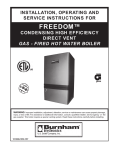
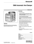
TEMPERATURE ADJUSTMENT
The TPI comes with a factory set temperature setting of 120°F and differential
setting of 10°F. Any temperature adjustment of the thermostat must be made
by qualified service personnel, as shown below.
WARNING: See SERVICE INFORMATION Water Temperature Regulation,
regarding safe water temperature before proceeding. Hot water can cause
scalding injuries.
1. Shut off or disconnect all electrical supply to heater.
2. Remove cover to TPI control.
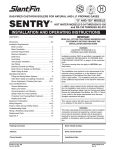
3. Adjust right side lever to the desired temperature. Moving lever down will decrease temperature. (See Figure at right and TPI Diagram 1).
NOTE: Markings on slide are approximate. Check temperature at faucet to ensure safe operating temperature.
4. Adjust left side lever to the desired differential. (See Figure at right and TPI Diagram 1) The TPI thermostat will call for heat when the tank temperature has fallen to the set differential degrees below the temperature set point.
®
®
20°
160°
150°
15°
140°
130°
10°
120°
5°
110°
Differential
Temperature
LED
flashing green = calling for heat
solid green = at temperature
Pump/TT red = error
24v
Probe
5. Reattach cover.
6. Reconnect electrical supply.
7. Check faucet temperature to verify desired temperature is achieved.
In order to set the temperature above 140°F {NOT RECOMMENDED} you must remove the SCALD
DANGER label attached to the temperature slide.
Caution: Do not increase temperature above 140°F without a properly installed mixing valve in the
system – See Water Temperature Regulation and SCALD WARNING.
Indicator Light operation:
The TPI thermostat has an integral indicator light at the top of the case.
(See TPI Diagram 1 or Inside Cover of TPI)
Indicator light will come on (Green) when TPI is powered.
When TPI is calling for heat, the Indicator light will blink.
When TPI is satisfied, the Indicator light will be solid.
During normal operation, Indicator light is Green.
If TPI detects a failure, Indicator light will flash Red. Replace TPI.
EMERGENCY
Should the heater be subject to flood, fire or other damaging conditions, turn the power and water to the
heater off. DO NOT place water heater in operation again until it has been thoroughly checked by qualified
service personnel.
TPI CONTROL - DIAGRAM 1
Indicating Light
Temperature Adjust
Differential
Adjust
TPI CONTROL - DIAGRAM 2
Screw A
10
TPI CONTROL - DIAGRAM 3
Outgoing 24V
wires to relay
or zone valve
Incoming 24V
power
connection
Outgoing 110V
wires to
circulator
Incoming 24V
power
connections
Chase Nipple
Conduit
NOTE: Use proper conduit
and chase nipple
11
FIGURE 1 - Installation Using Zone Valves
Installation Diagram Using Zone Valves
FIGURE 2 - Installation Using Circulator
Installation Diagram Using Separate Circulator
12
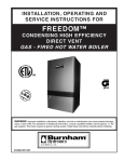
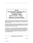
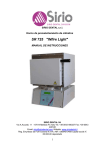
FIGURE 3 - Coil Detail & Tightening Sequence
Bolt
Small
outside
O-ring
Large
inside
O-ring
Steel Washer
Coil Plate
Plastic O-Ring
Housing
Tank
Flange
‘L’ Nut
Proper Tightening Sequence for Top Mount Coil
7
2
4
3
2
5
6
1
3
1
Incorrect
8
Correct
Note: Same as car tire lugs
CAUTION: Does not require excessive force to seal properly.
13
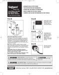
Circulator & Burner Control Wiring Diagrams
Standard Wiring for Circulator with Boiler
Maintaining a Temperature of 180°
®
®
20°
160°
150°
15°
Low Voltage
140°
130°
10°
120 Volts
120°
5°
110°
Differential
Temperature
LED
flashing green = calling for heat
solid green = at temperature
Pump/TT red = error
24v
Probe
L1 Hot
24v
120 Volts
L2 Neutral
Switched Hot
Circulator
Wiring for Burner Control L8148E
®
®
20°
160°
TV
150°
15°
T
W
140°
130°
10°
120°
5°
110°
Differential
Z
Transformer
Thermostat
Switching Relay
Temperature
LED
flashing green = calling for heat
solid green = at temperature
Pump/TT red = error
24v
Probe
Boiler
C1
B1
T
T
14
B2
C2
120 Volt
Burner
L1
L2
Circulator
Zone Valve Wiring Diagrams
Wiring for 3 Wire Zone Valve
Low Voltage
®
®
120 Volts
20°
160°
150°
15°
140°
130°
10°
Boiler
Connections
120°
5°
110°
T
Differential
T
flashing green = calling for heat
solid green = at temperature
Pump/TT red = error
24v
Temperature
LED
Probe
24v
1 2 3
Hot
Zone Valve
Neutral
120v
Wiring for 4 Zone Valve
®
®
20°
160°
150°
15°
140°
10°
130°
5°
110°
120°
Differential
LED
Motor
flashing green = calling for heat
solid green = at temperature
Pump/TT red = error
24v
4 Wire Zone Valve
Probe
End Switch
24v
Hot
T
Temperature
Neutral
120v
T
To Boiler Connections/Circulator
15
Switching relay Wiring Diagrams
Switching Relay R8845U or SR 501
Switching Relay SR-502 or SR-503
16
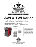
Switching relay Wiring Diagrams (con’t)
Switching Relay SR-504 with Priority Option
®
®
20°
160°
150°
15°
Low Voltage
120 Volts
140°
10°
130°
5°
110°
120°
Differential
Temperature
LED
flashing green = calling for heat
solid green = at temperature
Pump/TT red = error
24v
Probe
SR 504
ZONE 1
ZONE 2
ZONE 3
ZONE 4
PRIORIT Y
ZONE 4
ON
OFF
POWER
FOUR ZONE SWITCHING RELAY
WITH OPTIONAL PRIORIT Y
ZONE 1
ZONE 2
ZONE 3
ZONE 4
120 VOLT RELAY
COM / 24 VAC
X X
END SWITCH
ZONE 1
ZC
ZONE 2
ZONE 3
ZONE 4
POWER
ZR
120 VOLT CIRCULATORS
INPUT
FUSE 1 AMP
T T ON BOILER
Water Heater Circulator
120 VAC INPUT
17
HOW TO OBTAIN SERVICE ASSISTANCE
U.S. Boiler Company, Inc. – Burnham Hydronics does not have a service department or personnel to service your heater in the field. A qualified installer or service technician must do all service work. Therefore,
if you have any questions about your new water heater concerning service adjustment, repair, routine maintenance, or replacement - first contact your installer, plumbing contractor or service agency.
In the event that the contractor, for whatever reason, is unable to help, refer to the telephone directory commercial listings for qualified service assistance.
If neither action has solved your problem, contact U.S. Boiler Company, Inc. – Burnham Hydronics as follows to obtain the number of a qualified service person in your area:
SALES SUPPORT
U. B. BOILER COMPANY, INC.
BURNHAM HYDRONICS
P.O BOX 3079
LANCASTER, PA 17604
Or call 888-432-8887
When contacting Burnham Hydronics the following information should be made available:
A.Model and serial number of the water heater as listed on inside back cover of this manual or on the rating plate on the heater.
B.Address where water heater is installed.
C.Name and address of dealer from whom the heater was purchased and installer’s name and
address
D.Date of original installation and any service work performed since then.
E. Details of the problem as you can best describe.
F. List of people who have been contacted regarding the problem.
18
Alliance SL™ Indirect-Fired Water Heater
10/2/1 LIMITED WARRANTY
Ten Year Limited Tank Replacement Warranty
Two Year Limited Tank Replacement Labor Allowance
One Year Limited Parts Warranty
U.S. Boiler Company, Inc. – Burnham Hydronics, (hereinafter called the company) offers the following Limited Tank Replacement Warranty, Limited Tank Replacement Labor Allowance, and Limited Parts Warranty
to the original purchaser/owner of this stone-lined Alliance SL™ indirect-fired water heater. These warranties are not transferable beyond the original purchaser/owner, and are not valid if the tank is removed from
initial installation site. The Company reserves the right to require proof of purchase and inspection and/or
testing of tank as a condition of these warranties.
TEN (10) YEAR LIMITED TANK REPLACEMENT WARRANTY DURATION:
1. STANDARD DURATION: Ten (10) years from the date of manufacture as indicated by the serial
number.
2. OPTIONAL LIFETIME DURATION: (available to residential, single family homes only). For as long as the original purchaser owns the home in which the Alliance SL™ was originally installed. Optional Life
time replacement Warranty is not effective unless U.S. Boiler Company, Inc. – Burnham Hydronics receives completed registration card and payment within 30 days of purchase (see cover for details).
IF NO CARD IS RETURNED OR PAYMENT RECEIVED, THE REPLACEMENT WARRANTY WILL BE THE STANDARD 10-YEAR WARRANTY AND WILL BEGIN FROM THE MANUFACTURED DATE INDICATED BY THE SERIAL NUMBER ON THE ALLIANCE SL™ WATER HEATER.
COVERAGE: Replacement warranty covers only the storage tank for leaks caused by the corrosive effects of water under normal and proper use. Subject to prior Company approval.
COMPANY OBLIGATION: Repair of the original tank or replacement of the entire heater with a new
comparable model is at the option of the Company and constitutes the fulfillment of ALL obligations of the
Company hereunder. In replacing or repairing the Alliance SL™ Water Heater, the company reserves the
right to make such changes in details of design, construction or material as shall in their judgment constitute an improvement of former practices.
REPLACEMENT: When a replacement is made under the terms of this warranty, the replacement unit
will have a warranty of replacement and labor allowance only for the remaining time under the original
warranty. The Company reserves the right to require the return of the defective unit at the expense of the
purchaser.
LIMITATION: The duration of the tank replacement warranty on the tank assembly shall be reduced to a
period of five years if (1) the purchaser is a business, partnership or corporation, or if (2) the Alliance SL™
Water Heater is used for a commercial, institutional, industrial, non-residential or multi-application. All
repairs or replacements will be made F.O.B. the company. The purchaser must pay for transportation service, labor, installation, administrative fees or other costs involving the repair or replacement of such part.
YOUR ACTION: When you discover a defect, immediately notify the dealer from whom the heater was
purchased. If you cannot locate the dealer, contact the Company.
TWO (2) YEAR LIMITED TANK REPLACEMENT LABOR ALLOWANCE: The Company shall pay up to
a maximum of $200, for the labor to exchange a tank that is leaking due to the corrosive effects of water
within two years from date of installation. This labor allowance is for tank replacement only, and not for any
service work on the heater such as cleaning of the heat exchanger (due to the build-up of calcium or other
minerals or metals), leakage from plumbing connections, relief valves, heat exchanger gaskets, thermostats, or any other component of the heater. This labor must be performed by a qualified installer. Proof of
labor costs may be required as a condition of payment of the Tank Replacement Labor Allowance.
LIMITATION: All other repairs or replacements will be made F.O.B the Company. The purchaser must
pay for all transportation, service, labor, installation, administrative fees or other cost involving the repair of
replacement of such component parts.
YOUR ACTION: When you discover a defect, immediately notify the dealer from whom the heater was
purchased. If you cannot locate the dealer, contact the Company.
19
ONE (1) YEAR LIMITED PARTS WARRANTY
DURATION: The warranty is effective for one (1) year beginning with the date of original purchase. This
warranty shall begin from the date of manufacture as indicated by the serial number.
COVERAGE: The warranty covers any component part of the Alliance SL™ water heater proven to be
defective in workmanship or material. Subject to prior Company approval.
COMPANY OBLIGATION: The warranty covers any component of the Alliance SL™ water heater proven
to be defective in workmanship or material.
EXCLUSIONS AND LIMITATIONS
Limited Warranty and Tank Replacement Warranty are valid only if you comply with the following conditions
and limitations:
1. The Alliance SL™ Water Heater is correctly installed according to the installation manual provided with the unit and all applicable local and national codes.
2. The unit is operated within the factory calibrated temperature limits and water pressure not exceeding 150 psi.
3. Any failure or malfunction that does not result from improper or negligent operation, accident, abuse (including freezing), misuse, unauthorized alteration or improper maintenance.
4. Any failure or malfunction that does not result from failure to keep the tank full of potable water, free to circulate at all times; and free of damaging water sediment or scale deposits. In areas where adverse water conditions are suspected (i.e. calcium and other minerals), it is essential that the water be tested
and appropriate action be taken to prevent damage to the Alliance SL™ tank. It may be necessary to
remove the heat exchanger for cleaning to maintain maximum performance in poor water areas.
Diminished performance due to the build-up of calcium or other minerals, metals, or deposits on the heat exchanger is specifically not included in the coverage of these warranties.
5. THE FOREGOING EXPRESS LIMITED WARRANTIES ARE THE ONLY WARRANTIES OF ANY KIND,
EITHER EXPRESS OR IMPLIED. THERE ARE NO EXPRESS OR IMPLIED WARRANTIES OF
MERCHANTABILITY, FITNESS FOR A PARTICULAR PURPOSE, PERFORMANCE OR NON INFRINGEMENT, OR OTHER EXPRESS OR IMPLIED WARRANTIES. EXCEPT FOR THE LIMITED
WARRANTIES SET FORTH HEREIN, THE COMPANY DISCLAIMS ALL OTHER WARRANTIES OR CONDITIONS, EXPRESS OR IMPLIED, REGARDING THE PRODUCT OR ITS OR THEIR FITNESS FOR A PARTICULAR PURPOSE OR ITS OR THEIR MERCHANTABILITY. PURCHASER SHALL HAVE SOLE RESPONSIBILITY FOR SELECTING APPROPRIATE WATER HEATER FOR THE
PURCHASER’S NEEDS AND USE AND THE COMPANY DOES NOT WARRANT THE FITNESS FOR THE WATER HEATER’S INTENDED USE WITHIN ANY SPECIFIC SYSTEM. THE COMPANY DOES NOT AUTHORIZE COMPANY REPRESENTATIVES OR OTHER PERSONS TO VARY THE TERMS OF THE WARRANTIES HEREIN OR TO ASSUME FOR THE COMPANY ANY OTHER OBLIGATIONS OR LIABILITIES WITH RESPECT TO THIS PRODUCT.
6. The remedies set forth above shall be the sole and exclusive remedies for breach of any warranty.
IN NO EVENT SHALL THE COMPANY BE LIABLE FOR ANY INCIDENTAL OR CONSEQUENTIAL
DAMAGES WHATSOEVER.
Consumer Notifications: The foregoing warranty limitations shall be effective to the maximum extent
permitted by applicable law, and, to the extent that any such limitations would have an unconscionable
result or would otherwise be inconsistent with applicable law, such provision shall be reformed to the extent
necessary to avoid such unconscionable result or inconsistency. With respect to the limitations on implied
warranties set forth above, the Company hereby notifies each person to whom such warranty is made as
follows: Some states do not allow exclusions of such warranties, limitations on how long an implied warranty lasts or the exclusion or limitation of incidental or consequential damages, so the above limitations,
or exclusions, may not apply to you. The limited warranty gives you specific legal rights, and you may also
have other rights which vary from state to state.
20
MODEL & SERIAL NUMBER INFORMATION
The following information should be noted
At time of installation and retained
for Future reference.
Model No.
Serial No.
Date Installed
Dealer’s Name
Address
City
State
Zip
U.S. Boiler Company, Inc., – P.O. Box 3079 – Lancaster, PA 17604
www.burnham.com
21
NOTES
22
NOTES
23
Optional Lifetime Warranty Registration Card
Available to Residential, Single Family Homes Only
Yes, I wish to purchase the Optional Lifetime Warranty!
DATE _ _____________________________________________________________________
PURCHASER’S NAME _ _______________________________________________________
HOME ADDRESS ____________________________________________________________
CITY _____________________________ STATE _ _________________ ZIP ______________
HOME PHONE _____________________ EMAIL ____________________________________
ALLIANCE SL™ WATER HEATER SERIAL NUMBER (9 DIGITS)
COMPANY PURCHASED FROM ________________________________________________
INSTALLING COMPANY NAME __________________________________________________
ADDRESS _ _________________________________________________________________
CITY _____________________________ STATE _ _________________ ZIP ______________
COMPANY PHONE _ __________________________________________________________
DATE OF INSTALLATION _ _____________________________________________________
NOTE: To obtain the Optional Lifetime Warranty, this card must be filled out completely
and returned to U.S. Boiler Company, Inc. along with payment of one hundred dollars
($100) within 30 days of installation/occupancy.
METHOD OF PAYMENT (Check One):
CHECK PAYABLE TO: U.S. BOILER COMPANY, INC. ENCLOSED.
OR CHARGE MY:
VISA
MASTERCARD
CARD NUMBER ____________________________________________ “V” number _ _______
(Verification “V” number is last three digits of number printed on back of credit card.)
CREDIT CARD EXPIRATION DATE _ _____________________________________________
NAME ON CREDIT CARD ______________________________________________________
SIGNATURE _________________________________________________________________
Complete form, cut along dotted line, and return with payment to:
24
U. S. Boiler Company, Inc.
Attn: Alliance SL™ Extended Warranty Program
P.O. Box 3079 – Lancaster, PA 17604