1
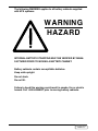
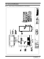
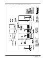
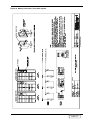
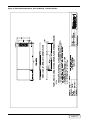
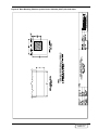
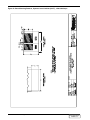
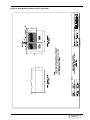
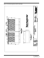
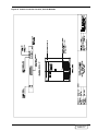
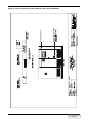
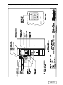
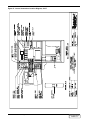
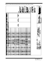
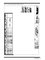
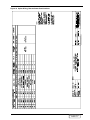
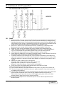
DISCONTINUED
PRODUCT
POWER PROTECTION
Series 600T™ UPS
Multi-Module Three Phase
500 kVA to 750 kVA, 60 Hz
Installation
Manual
The following WARNING applies to all battery cabinets supplied
with UPS systems:
WARNING
HAZARD
INTERNAL BATTERY STRAPPING MUST BE VERIFIED BY MANUFACTURER PRIOR TO MOVING A BATTERY CABINET.
Battery cabinets contain non-spillable batteries.
Keep units upright.
Do not stack.
Do not tilt.
Failure to heed this warning could result in smoke, fire or electric
hazard. Call 1-800-LIEBERT prior to moving battery cabinets.
DISCONTINUED
PRODUCT
Table of Contents
1.0
SAFETY PRECAUTIONS . . . . . . . . . . . . . . . . . . . . . . . . . . . . . . . . . . . . . . . . . . . . . . . . . . . . . . . . . . . . . 3
2.0
INSTALLATION CONSIDERATIONS . . . . . . . . . . . . . . . . . . . . . . . . . . . . . . . . . . . . . . . . . . . . . . . . . . . . . 4
2.1
Types of System Control Cabinets . . . . . . . . . . . . . . . . . . . . . . . . . . . . . . . . . . . . . . . . . . . . 6
3.0
UNLOADING AND HANDLING . . . . . . . . . . . . . . . . . . . . . . . . . . . . . . . . . . . . . . . . . . . . . . . . . . . . . . . . 7
4.0
INSPECTIONS
4.1
External Inspections . . . . . . . . . . . . . . . . . . . . . . . . . . . . . . . . . . . . . . . . . . . . . . . . . . . . . . . 8
4.2
Internal Inspections . . . . . . . . . . . . . . . . . . . . . . . . . . . . . . . . . . . . . . . . . . . . . . . . . . . . . . . . 8
5.0
EQUIPMENT LOCATION . . . . . . . . . . . . . . . . . . . . . . . . . . . . . . . . . . . . . . . . . . . . . . . . . . . . . . . . . . . . . 9
6.0
BATTERY I NSTALLATION
7.0
8.0
6.1
Battery Safety Precautions . . . . . . . . . . . . . . . . . . . . . . . . . . . . . . . . . . . . . . . . . . . . . . . . . 10
6.2
Matching Battery Cabinets . . . . . . . . . . . . . . . . . . . . . . . . . . . . . . . . . . . . . . . . . . . . . . . . . 13
6.3
Non-Standard Batteries. . . . . . . . . . . . . . . . . . . . . . . . . . . . . . . . . . . . . . . . . . . . . . . . . . . . 13
CONFIGURING YOUR NEUTRAL AND GROUND CONNECTIONS
7.1
Preferred Grounding Configuration, Wye-Connected Service. . . . . . . . . . . . . . . . . . . . . . 15
7.2
Grounding Configuration, Delta Source . . . . . . . . . . . . . . . . . . . . . . . . . . . . . . . . . . . . . . . 16
7.3
Preferred Grounding Configuration with Power-Tie Switchgear . . . . . . . . . . . . . . . . . . . 17
7.4
Grounding Configurations, Battery Systems . . . . . . . . . . . . . . . . . . . . . . . . . . . . . . . . . . . 18
WIRING C ONSIDERATIONS
8.1
Power Wiring . . . . . . . . . . . . . . . . . . . . . . . . . . . . . . . . . . . . . . . . . . . . . . . . . . . . . . . . . . . . 20
8.2
Control Wiring . . . . . . . . . . . . . . . . . . . . . . . . . . . . . . . . . . . . . . . . . . . . . . . . . . . . . . . . . . . 21
8.3
Battery Wiring . . . . . . . . . . . . . . . . . . . . . . . . . . . . . . . . . . . . . . . . . . . . . . . . . . . . . . . . . . . 22
9.0
WIRING C ONNECTIONS . . . . . . . . . . . . . . . . . . . . . . . . . . . . . . . . . . . . . . . . . . . . . . . . . . . . . . . . . . . . 25
10.0
WIRING I NSPECTION
Table 1 Power Wiring Terminals - Factory Supplied . . . . . . . . . . . . . . . . . . . . . . . . . . . . . . . . . . . 27
Table 2 Torque Specifications . . . . . . . . . . . . . . . . . . . . . . . . . . . . . . . . . . . . . . . . . . . . . . . . . . . . . 27
Table 3 Table 310-16 . . . . . . . . . . . . . . . . . . . . . . . . . . . . . . . . . . . . . . . . . . . . . . . . . . . . . . . . . . . . 28
11.0
INSTALLATION DRAWINGS . . . . . . . . . . . . . . . . . . . . . . . . . . . . . . . . . . . . . . . . . . . . . . . . . . . . . . . . . 29
12.0
APPENDIX A - SITE PLANNING DATA
Table 4 Series 600T Multi-Module Systems, 500-750 kVA - 480 Volt Input. . . . . . . . . . . . . . . . . 81
Table 5 Series 600T Multi-Module Systems, 500-750 kVA - 600 Volt Input . . . . . . . . . . . . . . . . 82
13.0
APPENDIX B - FIELD SUPPLIED LUGS
Table 6 One-Hole Lugs . . . . . . . . . . . . . . . . . . . . . . . . . . . . . . . . . . . . . . . . . . . . . . . . . . . . . . . . . . 83
DISCONTINUED
PRODUCT
i
DISCONTINUED
PRODUCT
List of Figures
Figure 1
Figure 2
Figure 3
Figure 4
Figure 5
Figure 6
Figure 7
Figure 8
Figure 9
Figure 10
Figure 11
Figure 12
Figure 13
Figure 14
Figure 15
Figure 16
Figure 17
Figure 18
Figure 19
Figure 20
Figure 21
Figure 22
Figure 23
Figure 24
Figure 25
Figure 26
Figure 27
Figure 28
Figure 29
Figure 30
Figure 31
Figure 32
Figure 33
Figure 34
Figure 35
Figure 36
Figure 37
Figure 38
Figure 39
Figure 40
Figure 41
Figure 42
Figure 43
Figure 44
Figure 45
Figure 46
Figure 47
UPS Multi-Module Unit Block Diagram . . . . . . . . . . . . . . . . . . . . . . . . . . . . . . . . . . . . . . . . . . . 5
System Control Cabinets . . . . . . . . . . . . . . . . . . . . . . . . . . . . . . . . . . . . . . . . . . . . . . . . . . . . . . . 6
Preferred Grounding Configuration, 480 or 600 VAC Input and Output . . . . . . . . . . . . . . . . 15
Grounding Configuration with Ungrounded Delta Source Input . . . . . . . . . . . . . . . . . . . . . . 16
Preferred Grounding Configuration, Power-Tie Systems . . . . . . . . . . . . . . . . . . . . . . . . . . . . 17
Battery Cabinet Grounding Configuration . . . . . . . . . . . . . . . . . . . . . . . . . . . . . . . . . . . . . . . . 18
Typical Multi-Module Configurations . . . . . . . . . . . . . . . . . . . . . . . . . . . . . . . . . . . . . . . . . . . . 23
Outline Drawing, 500 kVA Multi-Module UPS, 6-Pulse Rectifier. . . . . . . . . . . . . . . . . . . . . . 29
Outline Drawing, 500 kVA Multi-Module UPS, 12-Pulse Rectifier. . . . . . . . . . . . . . . . . . . . . 30
Outline Drawing, 625-750 kVA Multi-Module UPS, 6-Pulse Rectifier . . . . . . . . . . . . . . . . . . 31
Outline Drawing, 625-750 kVA Multi-Module UPS, 12-Pulse Rectifier . . . . . . . . . . . . . . . . . 32
Outline Drawing, System Control Cabinet (SCCT), 200-1200 Amps . . . . . . . . . . . . . . . . . . . 33
Outline Drawing, System Control Cabinet (SCCT), 1600-2500 Amps . . . . . . . . . . . . . . . . . . 34
Outline Drawing, System Control Cabinet (SCCT), 3000 Amps . . . . . . . . . . . . . . . . . . . . . . . 35
Outline Drawing, System Control Cabinet (SCCT) 4000 Amps . . . . . . . . . . . . . . . . . . . . . . . 36
Battery Power Pack, Size A . . . . . . . . . . . . . . . . . . . . . . . . . . . . . . . . . . . . . . . . . . . . . . . . . . . . 37
Battery Power Pack, Size B . . . . . . . . . . . . . . . . . . . . . . . . . . . . . . . . . . . . . . . . . . . . . . . . . . . . 38
Battery Power Pack, Three-Pack System . . . . . . . . . . . . . . . . . . . . . . . . . . . . . . . . . . . . . . . . . 39
Base Mounting Patterns, 500 kVA Module, 12-Pulse Rectifier . . . . . . . . . . . . . . . . . . . . . . . . 40
Base Mounting Patterns, 625-750 kVA Module, 6-Pulse . . . . . . . . . . . . . . . . . . . . . . . . . . . . . 41
Base Mounting Patterns, 625-750 kVA Module, 12-Pulse Rectifier . . . . . . . . . . . . . . . . . . . . 42
Base Mounting Patterns, System Control Cabinets (SCCT) 200-1200 Amps . . . . . . . . . . . . . 43
Base Mounting Patterns, System Control Cabinet (SCCT), 1600-2500 Amps . . . . . . . . . . . . 44
Base Mounting Patterns (SCCT), 3000 Amps. . . . . . . . . . . . . . . . . . . . . . . . . . . . . . . . . . . . . . 45
Base Mounting Patterns (SCCT), 4000 Amps. . . . . . . . . . . . . . . . . . . . . . . . . . . . . . . . . . . . . . 46
Shipping Split Detail, 500 kVA Multi-Module UPS, 12-Pulse Rectifier . . . . . . . . . . . . . . . . . 47
Shipping Split Detail, 625-750 kVA Multi-Module UPS, 6-Pulse Rectifier . . . . . . . . . . . . . . 48
Shipping Split Detail, 625-750 kVA Multi-Module UPS, 12-Pulse Rectifier . . . . . . . . . . . . . 49
Terminal Details, 500 kVA Module, 6-Pulse Rectifier . . . . . . . . . . . . . . . . . . . . . . . . . . . . . . . 50
Terminal Details, 500 kVA Module, 12-Pulse Rectifier . . . . . . . . . . . . . . . . . . . . . . . . . . . . . . 51
Terminal Details, 625 & 750 kVA Modules, 6-Pulse and 12-Pulse . . . . . . . . . . . . . . . . . . . . . 52
Terminal Details, 750 kVA with Input Bus Bars . . . . . . . . . . . . . . . . . . . . . . . . . . . . . . . . . . . 53
Control Wiring, External Interconnections, Standard UPS Module . . . . . . . . . . . . . . . . . . . 54
Control Connection Location, 500 kVA Modules . . . . . . . . . . . . . . . . . . . . . . . . . . . . . . . . . . . 55
Control Connection Location Diagram, 625 & 750 kVA Modules . . . . . . . . . . . . . . . . . . . . . . 56
Control Connection Location Diagram, SCCC & SCCI . . . . . . . . . . . . . . . . . . . . . . . . . . . . . . 57
Control Connection Location Diagram, SCCT . . . . . . . . . . . . . . . . . . . . . . . . . . . . . . . . . . . . . 58
Control Wire List, External Interconnections, Standard UPS Module . . . . . . . . . . . . . . . . . 59
Control Wire List, External Interconnections, System Control Cabinet, Part 1 of 3 . . . . . . . 60
Control Wire List, External Interconnections, Standard SCC, Part 2 of 3 . . . . . . . . . . . . . . 61
Control Wire List, External Interconnections, Standard SCC, Part 3 of 3 . . . . . . . . . . . . . . . 62
Control Wire List, External Interconnections, Alarm Status Contacts . . . . . . . . . . . . . . . . . 63
Option Wiring, Maintenance Bypass Interlock . . . . . . . . . . . . . . . . . . . . . . . . . . . . . . . . . . . . 64
Option Wiring, Remote Status Panel Interface . . . . . . . . . . . . . . . . . . . . . . . . . . . . . . . . . . . . 65
Option Wiring, Internal Modem . . . . . . . . . . . . . . . . . . . . . . . . . . . . . . . . . . . . . . . . . . . . . . . . 66
Option Wiring, Customer Alarm Interface, SCC with Momentary-Duty Static Switch . . . . 67
Option Wiring, Customer Alarm Interface, SCC with Continuous-Duty Static Switch. . . . . 68
DISCONTINUED
PRODUCT
iii
Figure 48
Figure 49
Figure 50
Figure 51
Figure 52
Figure 53
Figure 54
Figure 55
Figure 56
Figure 57
Figure 58
iv
Option Wiring, Battery Temperature Sensor . . . . . . . . . . . . . . . . . . . . . . . . . . . . . . . . . . . . . .
Option Wiring, SNMP Interface . . . . . . . . . . . . . . . . . . . . . . . . . . . . . . . . . . . . . . . . . . . . . . . .
External Interconnections, Module 1/SCC, Cable Groups 21 and 22 . . . . . . . . . . . . . . . . . . .
External Interconnections, Module 2/SCC, Cable Groups 21 and 22 . . . . . . . . . . . . . . . . . . .
Wiring Configurations, UPS Video Display Terminal . . . . . . . . . . . . . . . . . . . . . . . . . . . . . . .
Module Battery Disconnect, 600-1200 Amps, without Input Isolation Transformer . . . . . . .
Module Battery Disconnect, 300-1200 Amps, with Input Isolation Transformer . . . . . . . . . .
Remote Status Panel, Surface Mount . . . . . . . . . . . . . . . . . . . . . . . . . . . . . . . . . . . . . . . . . . . .
Circuit Breaker Schedule, Multi-Module UPS, 300-750 kVA . . . . . . . . . . . . . . . . . . . . . . . . .
Circuit Breaker Schedule, Merlin-Gerin Breakers, SCCT, 200-4000 Amps . . . . . . . . . . . . . .
Circuit Breaker Schedule, General Electric Breakers, SCCT, 200-4000 Amps . . . . . . . . . . .
69
70
71
72
73
74
75
76
77
78
79
DISCONTINUED
PRODUCT
IMPORTANT SAFETY INSTRUCTIONS
Save These Instructions.
This manual contains important instructions that should be followed during installation of your
Series 600T UPS and batteries.
WARNING
EXERCISE EXTREME CARE WHEN HANDLING UPS CABINETS
TO AVOID EQUIPMENT DAMAGE OR INJURY TO PERSONNEL.
THE UPS MODULE WEIGHT RANGES UP TO 12,000 POUNDS
(5,455 KG), INCLUDING INPUT TRANSFORMER. THE BATTERY
CABINETS WEIGH BETWEEN 3000 POUNDS (1364 KG) AND 4900
POUNDS (2227 KG).
LOCATE CENTER OF GRAVITY SYMBOLS BEFORE HANDLING
EACH CABINET. TEST LIFT AND BALANCE THE CABINETS
BEFORE TRANSPORTING. MAINTAIN MINIMUM TILT FROM
VERTICAL AT ALL TIMES.
SLOTS AT THE BASE OF THE MODULES AND BATTERY
CABINETS ARE INTENDED FOR FORKLIFT USE. BASE SLOTS
WILL SUPPORT THE UNIT ONLY IF THE FORKS ARE
COMPLETELY BENEATH THE UNIT.
SYSTEM CONTROL CABINETS (SCC’S) HAVE HOLES
INTENDED FOR RIGGING BARS OR CHAINS. PREVENT
CHAINS OR CABLES FROM CONTACTING CABINET BY USING
SPREADER BAR AND ADEQUATE PADDING.
FOLLOW ALL BATTERY SAFETY PRECAUTIONS WHEN
INSTALLING, CHARGING, OR SERVICING BATTERIES. IN
ADDITION TO THE HAZARD OF ELECTRIC SHOCK, GAS
PRODUCED BY BATTERIES CAN BE EXPLOSIVE AND
SULFURIC ACID CAN CAUSE SEVERE BURNS.
IN CASE OF FIRE INVOLVING ELECTRICAL EQUIPMENT,
ONLY CARBON DIOXIDE FIRE EXTINGUISHERS, OR THOSE
APPROVED FOR USE IN ELECTRICAL FIRE FIGHTING,
SHOULD BE USED.
EXTREME CAUTION IS REQUIRED WHEN PERFORMING
MAINTENANCE.
BE CONSTANTLY AWARE THAT THE UPS SYSTEM CONTAINS
HIGH DC AS WELL AS AC VOLTAGES.
CHECK FOR VOLTAGE WITH BOTH AC AND DC VOLTMETERS
PRIOR TO MAKING CONTACT.
DISCONTINUED
PRODUCT
1
WARNING
LOCATE CENTER OF GRAVITY SYMBOLS
AND DETERMINE UNIT WEIGHT
BEFORE HANDLING CABINET.
If you require assistance for any reason, call the toll-free Liebert Global Services number; 1-800543-2378. For LGS to assist you expediently, please have the following information available:
Part Numbers:
______________________________________________________________
Serial Numbers:
______________________________________________________________
kVA Rating:
______________________________________________________________
Date Purchased:
______________________________________________________________
Date Installed:
______________________________________________________________
Location:
______________________________________________________________
Input Voltage:
______________________________________________________________
Output Voltage:
______________________________________________________________
Battery Reserve Time: ______________________________________________________________
2
DISCONTINUED
PRODUCT
1.0
SAFETY PRECAUTIONS
Read this manual thoroughly, paying special attention to the sections that apply to you, before
working with the UPS. Retain this manual for use by installing personnel.
Under typical operation and with all UPS doors closed, only normal safety precautions are necessary. The area around the UPS system should be kept free from puddles of water, excess moisture, or debris.
Special safety precautions are required for procedures involving handling, installation, and maintenance of the UPS system or the battery. Observe all safety precautions in this manual before
handling or installing the UPS system. Observe all precautions in the Operation and Maintenance Manual, before as well as during performance of all maintenance procedures. Observe all
battery safety precautions before working on or near the battery.
This equipment contains several circuits that are energized with high voltage. Only test
equipment designated for troubleshooting should be used. This is particularly true for oscilloscopes. Always check with an AC and DC voltmeter to ensure safety before making contact or
using tools. Even when the power is turned Off, dangerously high potentials may exist at the
capacitor banks and at the batteries.
ONLY qualified service personnel should perform maintenance on the UPS system.
When performing maintenance with any part of the equipment under power, service personnel
and test equipment should be standing on rubber mats. The service personnel should wear insulating shoes for isolation from direct contact with the floor (earth ground).
Unless all power is removed from the equipment, one person should never work alone. A second
person should be standing by to assist and summon help in case an accident should occur.
Four types of messages are used throughout the manual to stress important text. Carefully read
the text below each Danger, Warning, Caution, and Note and use professional skills and prudent
care when performing the actions described by that text.
A Danger signals immediate hazards resulting in severe personal injury or death. For example:
DANGER
A DANGER SIGNALS IMMEDIATE HAZARDS WHICH WILL
RESULT IN SEVERE PERSONAL INJURY OR DEATH.
A Warning signals the presence of a possible serious, life-threatening condition. For example:
WARNING
LETHAL VOLTAGES MAY BE PRESENT WITHIN THIS UNIT
EVEN WHEN IT IS APPARENTLY NOT OPERATING. OBSERVE
ALL CAUTIONS AND WARNINGS IN THIS MANUAL. FAILURE
TO DO SO COULD RESULT IN SERIOUS INJURY OR DEATH. DO
NOT WORK ON OR OPERATE THIS EQUIPMENT UNLESS YOU
ARE FULLY QUALIFIED TO DO SO!! NEVER WORK ALONE.
A Caution indicates a condition that could seriously damage equipment and possibly injure personnel. For example:
CAUTION
Extreme care is necessary when removing shoring braces. Do not
strike the cabinet with hammers or other tools.
A Note emphasizes important text. If the note is not followed, equipment could be damaged or
may not operate properly. For example:
NOTE
If the UPS system has a blown fuse, the cause should be determined before
you replace the fuse. Contact Liebert Global Services.
Safety Precautions
DISCONTINUED
PRODUCT
3
2.0
INSTALLATION CONSIDERATIONS
Install your Series 600T UPS in accordance with the submittal drawing package and the following procedures.
A Liebert authorized representative must perform the initial system check-out and start-up to
ensure proper system operation. Equipment warranties will be voided unless system start-up is
performed by a Liebert authorized representative. Contact your local Liebert sales representative
or Liebert Global Services at 1-800-543-2378 to arrange for system start-up.
CAUTION
Read this manual thoroughly before attempting to wire or
operate the unit. Improper installation is the most significant
cause of UPS start-up problems.
Do not install this equipment near gas or electric heaters. It is
preferable to install the UPS in a restricted location to prevent
access by unauthorized personnel.
1. Proper planning will speed unloading, location, and connection of the UPS. Refer to
Figure 8 through Figure 58 and Appendix A - Site Planning Data.
2. Refer to information later in this manual regarding the optional Battery Cabinets and
Transformer Cabinets. Observe all battery safety precautions when working on or
near the battery.
3. Use the shortest output distribution cable runs possible, consistent with logical equipment
arrangements and with allowances for future additions if planned.
4. Recommended ambient operating temperature is 25°C (77°F). Relative humidity must be less
than 95%, non-condensing. Note that room ventilation is necessary, but air conditioning may
not be required. Maximum ambient operating temperature is 40°C (104°F) without derating.
The batteries should not exceed 25°C (77°F). At elevations above 4,000 feet (1219 meters)
derating may be required (consult your Liebert sales representative).
5. Even though your Liebert UPS unit is at least 93% efficient, the heat output is substantial.
For more specific information, see Appendix A - Site Planning Data. Be sure
environmental conditioning systems can accommodate this BTU load, even during utility
outages.
6. The routing (inside the facility) to the installation site, as well as the floor at the final
equipment location, must be capable of supporting the cabinet weight and the weight of any
moving equipment. The modules weigh up to 12,000 pounds. The battery cabinets weigh
between 3000 and 4900 pounds. The System Control Cabinets weigh between 1000 and 2550
pounds. Refer to Appendix A - Site Planning Data.
7. Plan the routing to ensure that the unit can move through all aisleways, doorways, and
around corners without risking damage. If the modules and batteries must be moved by
elevator, check the size of the door openings and the weight-carrying capacity of the elevator.
WARNING
LOCATE CENTER OF GRAVITY SYMBOLS
AND DETERMINE UNIT WEIGHT BEFORE
HANDLING CABINET.
4
Installation Considerations
DISCONTINUED
PRODUCT
Figure 1
UPS Multi-Module Unit Block Diagram
Installation Considerations
DISCONTINUED
PRODUCT
5
Figure 2
System Control Cabinets
SCCT Dimensions
Amp
WxD
Weight
Ratings
(Inches)
(lbs.)
200-1200
37x37
1000
1600
62x48
1525
2000-2500
62x48
2850
3000
62x48
3100
4000
138x60
5850
2.1
6
Types of System Control Cabinets
1. SCCT is a stand-alone cabinet containing system control logic for up to six UPS modules,
static bypass switch, manually operated disconnects for the static bypass switch, and two
motor-operated system breakers. The SCCT is painted the same color as the Liebert UPS, but
does not match the sheet metal style of the UPS.
2. SCCI has the system control logic, circuit breakers and static bypass switch integrated into a
switchboard cabinet manufactured by others.
3. SCCC is an integrated configuration like the SCCI with the static bypass switch rated for
continuous duty.
Installation Considerations
DISCONTINUED
PRODUCT
3.0
UNLOADING AND HANDLING
The UPS module is shipped in one cabinet to allow easy handling at the site. Because the weight
distribution in the cabinet is uneven, use extreme care during handling and transport. Your
installation may also include Battery Cabinets and a System Control Cabinet.
WARNING
EXERCISE EXTREME CARE WHEN HANDLING UPS CABINETS
TO AVOID EQUIPMENT DAMAGE OR INJURY TO PERSONNEL.
THE UPS MODULE WEIGHS UP TO 12,000 POUNDS. BATTERY
CABINETS WEIGH BETWEEN 3100 AND 4900 POUNDS.
LOCATE CENTER OF GRAVITY SYMBOLS BEFORE HANDLING
CABINET. TEST LIFT AND BALANCE THE CABINET BEFORE
TRANSPORTING. MAINTAIN MINIMUM TILT FROM VERTICAL
AT ALL TIMES.
SLOTS AT THE BASE OF THE MODULES AND BATTERY
CABINETS ARE INTENDED FOR FORKLIFT USE. BASE SLOTS
WILL SUPPORT THE UNIT ONLY IF THE FORKS ARE
COMPLETELY BENEATH THE UNIT.
SYSTEM CONTROL CABINETS (SCC’S) HAVE HOLES
INTENDED FOR RIGGING BARS OR CHAINS. PREVENT
CHAINS OR CABLES FROM CONTACTING CABINET BY USING
SPREADER BAR AND ADEQUATE PADDING.
To reduce the possibility of shipping damage, cabinets are shored with 2x4 bracing, secured with
screw-type nails. This shoring must be carefully removed prior to unloading.
CAUTION
Extreme care is necessary when removing shoring braces. Do not
strike cabinet with hammers or other tools.
Unloading and Handling
DISCONTINUED
PRODUCT
7
4.0
4.1
4.2
8
INSPECTIONS
External Inspections
1. While the UPS system is still on the truck, inspect the equipment and shipping container(s)
for any signs of damage or mishandling. Do not attempt to install the system if damage is
apparent. If any damage is noted, file a damage claim with the shipping agency within 24
hours and contact Liebert Global Services at 1-800-543-2378 to inform them of the damage
claim and the condition of the equipment.
2. Locate the bag containing the keys for the front access door. The bag is attached to the
cabinet.
3. Compare the contents of the shipment with the bill of lading. Report any missing items to the
carrier and to Liebert Global Services immediately.
4. Check the nameplate on the cabinets to verify that the model numbers correspond with the
one specified. Record the model numbers and serial numbers in the front of this installation
manual. A record of this information is necessary should servicing become required.
Internal Inspections
1.
2.
3.
4.
5.
Verify that all items have been received.
If spare parts were ordered, verify arrival.
Open doors and remove cabinet panels to check for shipping damage to internal components.
Check for loose connections or unsecured components in the cabinet(s).
Check for installation of circuit breaker line safety shields. There should be no exposed circuit
breaker terminals when the cabinet doors are opened.
6. Check for any unsafe condition that may be a potential safety hazard.
7. UPS modules are shipped with internally mounted shipping brackets. The shipping brackets
(painted orange) must be removed from the rear (remove rear panels).
Inspections
DISCONTINUED
PRODUCT
5.0
EQUIPMENT LOCATION
1. Handle cabinet(s) in accordance with the Section 1.0 Safety Precautions and 3.0
Unloading & Handling. Use a suitable material handling device to move cabinet to its final
location. Exercise extreme care because of the uneven weight distribution. Carefully
lower the cabinet to the floor.
2. Verify that the UPS system is installed in a clean, cool and dry location.
3. Installation and serviceability will be easier if adequate access is provided on all sides of the
equipment, but only front access is required.
a. Verify that there is adequate clearance to open cabinet doors. See drawings and local
codes (4 feet is recommended).
b. Verify that there is adequate area in front of circuit breakers to perform maintenance.
Check installation drawings for location of breakers. Check with local codes.
c. Verify that there is adequate clearance above all cabinets to allow exhaust air to flow
without restriction (2 feet minimum, unobstructed).
Equipment Location
DISCONTINUED
PRODUCT
9
6.0
BATTERY INSTALLATION
6.1
Battery Safety Precautions
Servicing of batteries should be performed or supervised by personnel knowledgeable of batteries
and the required precautions. Keep unauthorized personnel away from batteries.
When replacing batteries, use the same number and type of batteries.
CAUTION
Lead-acid batteries contain hazardous materials. Batteries must
be handled, transported, and recycled or discarded in accordance
with federal, state, and local regulations. Because lead is a toxic
substance, lead-acid batteries should be recycled rather than
discarded.
Do not open or mutilate the battery or batteries. Released
electrolyte is harmful to the skin and eyes. It may be toxic. Do not
dispose of battery or batteries in a fire. The battery may explode.
A battery can present a risk of electrical shock and high short
circuit current. The following precautions should be observed
when working on batteries:
1.
2.
3.
4.
5.
Remove watches, rings, or other metal objects.
Use tools with insulated handles.
Wear rubber gloves and boots.
Do not lay tools or metal parts on top of batteries.
Disconnect charging source prior to connecting or
disconnecting battery terminals.
6. Determine if battery is inadvertently grounded. If
inadvertently grounded, remove source of ground. Contact
with any part of a grounded battery can result in electrical
shock. The likelihood of such shock will be reduced if such
grounds are removed during installation and maintenance.
Lead-acid batteries can present a risk of fire because they
generate hydrogen gas. The following procedures should be
followed:
1. DO NOT SMOKE when near batteries.
2. DO NOT cause flame or spark in battery area.
3. Discharge static electricity from body before touching
batteries by first touching a grounded metal surface.
10
Battery Installation
DISCONTINUED
PRODUCT
Battery Safety Precautions in French Per CSA Requirements
Instructions Importantes Concernant La Sécurité
Conserver Ces Instructions
ADVERTISSEMENT
DES PIECES SOUS ALIMENTATION SERONT LAISSEES SANS
PROTECTION DURANT CES PROCEDURES D’ENTRETIEN. UN
PERSONNEL QUALIFIE EST REQUIS POUR EFFECTUER CES
TRAVAUX.
LES FUSIBLES A C.C. DE LA BATTERIE D’ACCUMULATEURS
OPERENT EN TOUT TEMPS A LA TENSION NOMINALE. LA
PRESENCE D’UN FUSIBLE A C.C. BRULE INDIQUE UN
PROBLEME SERIEUX. LE REMPLACEMENT DE CE FUSIBLE,
SANS AVOIR DETERMINE LES RAISONS DE LA
DEFECTUOSITE, PEUT ENTRAINER DES BLESSURES OU DES
DOMMAGES SERIEUX A L’EQUIPEMENT. POUR ASSISTANCE,
APPELER LE DEPARTEMENT DE SERVICE A LA CLIENTELE
DE LIEBERT.
DANGER
Les accumulateurs plomb-acide contiennent de la matière
comportant un certain risque. Les accumulateurs doivent être
manipulés, transportés et recyclés ou éliminés en accord avec les
lois fédérales, provinciales et locales. Parce que le plomb est une
substance toxique, les accumulateurs plomb-acide devraient être
recyclés plutôt qu’éliminés.
Il ne faut pas brûlé le ou les accumulateurs. L’accumulateur
pourrait alors explosé.
Il ne faut pas ouvrir ou endommager le ou les accumulateurs.
L’électrolyte qui pourrait s’en échapper est dommageable pour la
peau et les yeux.
Un accumulateur représente un risque de choc électrique et de
haut courant de court-circuit. Lorsque des accumulateurs sont
manipulés, les mesures préventives suivantes devraient être
observées:
1.
2.
3.
4.
Retirer toutes montre, bagues ou autres objets métalliques.
Utiliser des outils avec manchon isolé.
Porter des gants et des bottes de caoutchouc.
Ne pas déposer les outils ou les pièces métalliques sur le
dessus des accumulateurs.
5. Interrompre la source de charge avant de raccorder ou de
débrancher les bornes de la batterie d’accumulateurs.
6. Déterminer si l’accumulateur est mis à la terre par erreur. Si
oui, défaire cette mise à la terre. Tout contact avec un
accumulateur mis à la terre peut se traduire en un choc
électrique. La possibilitié de tels chocs sera réduité si de telles
mises à la terre sont débranchées pour la durée de
l’installation ou de l’entretien.
Battery Installation
DISCONTINUED 11
PRODUCT
Les accumulateurs plomb-acide présentent un risque d’incendie
parce qu’ils génèrent des gaz à l’hydrogène. Les procédures
suivantes devront être respectées.
1. NE PAS FUMER lorsque près des accumulateurs.
2. NE PAS produire de flammes ou d’étincelles près des
accumulateurs.
3. Décharger toute électricité statique présente sur votre corps
avant de toucher un accumulateur en touchant d’abord une
surface métallique mise à la terre.
DANGER
L’électrolyte est un acide sulfurique dilué qui est dangereux au
contact de la peau et des yeux. Ce produit est corrosif et aussi
conducteur electrique. Les procédures suivantes devront être
observées:
1. Porter toujours des vêtements protecteurs ainsi que des
lunettes de protection pour les yeux.
2. Si l’électrolyte entre en contact avec la peau, nettoyer
immédiatement en rincant avec de l’eau.
3. Si l’électrolyte entre en contact avec les yeux, arroser
immédiatement et généreusement avec de l’eau. Demander
pour de l’aide médicale.
4. Lorsque l’électrolyte est renversée, la surface affectée devrait
être nettoyée en utilisant un agent neutralisant adéquat. Une
pratique courante est d’utiliser un mélange
d’approximativement une livre (500 grammes) de bicarbonate
de soude dans approximativement un gallon (4 litres) d’eau. Le
mélange de bicarbonate de soude devra être ajouté jusqu’à ce
qu’il n’y ait plus apparence de réaction (mousse). Le liquide
résiduel devra être nettoyé à l’eau et la surface concernée
devra être asséchée.
12
Battery Installation
DISCONTINUED
PRODUCT
6.2
Matching Battery Cabinets
Two sizes of optional battery cabinets are available. Refer to Figure 16 to Figure 18. The battery
cabinet cells range from 90 to 150 Ampere-hours. The same model battery cabinet may be paralleled in multiple cabinet strings for additional capacity. Battery capacity (in minutes) at your
installation will depend on cabinet model, number of cabinets, and amount of critical load on the
UPS.
1. Handling. The Battery Cabinet weighs 3000 to 4900 pounds. Forklift slots are provided for
easy handling.
2. Cabinet Inspection. Remove all panels and visually inspect the batteries, bus connections,
and cabinet for any damage. Exercise caution; voltage is present within the Battery
Cabinet even before installation. If there are signs of damage, do not proceed. Call Liebert
Global Services at 1-800-543-2378.
3. Battery Storage. The batteries used in the Battery Cabinet have an excellent charge
retaining characteristic. The batteries can be stored for up to six months without any
appreciable deterioration. Self-discharge rate of the batteries is approximately 3% per month
when the batteries are stored in temperatures of 15°C to 25°C (59°F to 77°F). If the Battery
Cabinet is planned to be stored for longer than six months, contact Liebert Customer Service
for recommended action.
4. Installation. The Battery Cabinet(s) can be located conveniently next to each UPS module.
The front-access-only-design eliminates side and rear service clearance requirements.
• Environment. Locate the Battery Cabinet in a clean, dry environment. Recommended
temperature range for optimum performance and lifetime is 20°C (68°F) to 25°C (77°F).
• Service Clearance. Allow front access to the Battery Cabinet at all times for maintenance and servicing. Electrical codes require that the Battery Cabinet be installed with no
less than 3 feet (1 meter) of clearance at the front of the cabinet when operating. Side and
rear panels do not require service clearance.
• Side Panels. Remove protective side panels to connect cabinets together. Panels are
retained at the bottom with three screws.
• Shield Plate. If the Battery Cabinets are bolted to the side of the UPS module, the shield
plate inside the Battery Cabinet should be on the side toward the UPS module for proper
UPS airflow. Move the shield if required by your Battery Cabinet location.
• Cables. Cables may be run between the cabinets through cutouts in the top of the cabinet, eliminating the need for external conduit runs. Route cables before moving cabinets into final position for bolting together. Remove top panels for access, if
required. No top or bottom entry cables are required, except for remotely located cabinets
which require conduits. Refer to Figure 16 through Figure 18.
• Built-In Cabinets. Matching Battery Cabinets are designed as a bolt-on section to the
side of the UPS module cabinet. Use bolts (3/8"-16 x 1-1/4") to connect cabinet frames at
posts, two places front and two places rear. Brackets are provided to make rear connections easier from inside the cabinet.
6.3
Non-Standard Batteries
When batteries other than a matching Battery Cabinet are used (not recommended), a remote
battery disconnect switch with overcurrent protection is required per the National Electrical
Code. Refer to Figure 53 and Figure 54. Contact your Liebert sales representative regarding
this option.
1. Install battery racks/cabinets and batteries per manufacturer’s installation and maintenance
instructions.
2. Verify battery area has adequate ventilation and battery operating temperature complies
with manufacturer’s specification.
If you have any questions concerning batteries, battery racks, or accessories, contact Liebert Global Services at 1-800-543-2378.
Battery Installation
DISCONTINUED 13
PRODUCT
7.0
CONFIGURING YOUR NEUTRAL AND GROUND CONNECTIONS
Improper grounding is the largest single cause of UPS installation and start-up problems. This is
not an easy subject, since grounding techniques vary significantly from site to site, depending on
several factors. The questions you should ask are:
• What is the configuration of the input power source? Most of the recommended schemes for
UPS grounding require grounded-wye service. The UPS system requires a bypass neutral for
sensing and monitoring the quality of the bypass input. If the building service is straight
delta or corner-grounded delta, contact your Liebert representative for details of the Artificial
Neutral or Isolated Neutral kits for the System Control Cabinet.
• What are the UPS input and output voltages? Systems with 480 VAC input and output have
significantly different needs than systems with 208/208 VAC.
• What is the connected load? Does the critical load consist of one or more Power Distribution
Units (PDUs)? Do the PDUs have isolation transformers?
The following sections discuss recommended grounding procedures for various system configurations.
NOTE
Some UPS modules are equipped with input isolation transformers.
However, these transformers have no effect upon any system grounding
considerations. These modules will be grounded exactly as shown in the
following examples.
14
Configuring Your Neutral and Ground Connections
DISCONTINUED
PRODUCT
7.1
Preferred Grounding Configuration, 480 or 600 VAC Input and Output, Isolated
Power Distribution Units, Wye-Connected Service
Figure 3
Preferred Grounding Configuration, 480 or 600 VAC Input and Output
The most-common configuration of Series 600T UPS Multi-Module Systems is with 480 VAC
input, 480 VAC output, and a connected load consisting of multiple Power Distribution Units
(PDUs) with isolation transformers in the PDUs to produce 208 VAC. For Canadian customers,
the UPS modules usually have 600 VAC input and output. The same principles apply if the connected load is an isolation transformer feeding various loads. Figure 3 above shows a typical
installation. The Maintenance Bypass Switchgear is shown separately for clarity, but is usually
contained within the System Control Cabinet (SCC).
Notice that the UPS module input and the system bypass input are connected to a grounded-wye
service. In this configuration, the UPS module is not considered a separately derived source.
All of the UPS module output neutrals are solidly connected to the SCC neutral. The SCC neutral
is solidly connected to the building service neutral, which is bonded to the grounding conductor at
the service entrance equipment.
The isolation transformers in the PDUs can be considered separately derived sources. Therefore
the PDU neutrals should be bonded to the PDU grounding conductor and connected to a local
grounding electrode in compliance with NEC 250-26.
NOTE
Impedance-grounded wye sources require an Isolated Neutral Kit in
addition to the grounding and neutral conductors shown above.
Configuring Your Neutral and Ground Connections
DISCONTINUED 15
PRODUCT
7.2
Grounding Configuration, 480 or 600 VAC Input and Output, Delta Source
Figure 4
Grounding Configuration with Ungrounded Delta Source Input
As previously mentioned, Series 600T UPS systems require a bypass input netrual for sensing
and monitoring. With a wye-connected input source, the installer should always connect the
building service neutral to the System Control Cabinet (SCC) output neutral to achieve this.
When the building service is delta-connected, however, the installer must take special steps to
ensure reliable UPS functioning.
If building service is ungrounded delta (and there is no intent to operate with one corner of the
delta grounded, either on purpose or accidentally), the SCC requires the Series 600T Artificial
Neutral Kit for proper operation. This kit uses a resistor network to create a reference point for
the bypass input. In this case, the SCC output neutral must be bonded to the SCC ground.
If the building service is corner-grounded delta or an Impedance-grounded wye, the SCC requires
the Isolated Neutral Kit. This kit uses control isolation transformers to create a reference point.
For this application, the SCC output neutral must not be bonded to the SCC ground.
NOTE
The Artificial Neutral Kit introduces a maximum current of 0.3 amps to
ground. Take care to ensure that this does not interfere with the operation
of any upstream ground-fault detection devices.
16
Configuring Your Neutral and Ground Connections
DISCONTINUED
PRODUCT
7.3
Preferred Grounding Configuration with Power-Tie Switchgear
Figure 5
Preferred Grounding Configuration, Power-Tie Systems
Multi-Module Systems can be used with Power-Tie switchgear to provide dual critical load busses.
The Power-Tie switchgear permits transferring critical loads from one critical bus to the other so
that one UPS system and associated breakers can be de-energized for maintenance. Certain configurations of Power-Tie equipment also permit the operator to continuously parallel the output of
both UPS systems.
In tied systems, each SCC must have its neutral solidly connected to the Power-Tie switchgear
neutral. The UPS modules, as usual, must have their output neutrals solidly connected to their
respective SCC neutrals. There should not be a connection between the service entrance neutral
and either the SCC or module neutrals.
NOTE
It is essential to run a neutral connection between the tie switchgear and
both SCCs as shown in the illustration above.
Configuring Your Neutral and Ground Connections
DISCONTINUED 17
PRODUCT
7.4
Grounding Configurations, Battery Systems
Figure 6
Battery Cabinet Grounding Configuration
Large, open-rack battery systems are normally either locally grounded or left ungrounded,
depending on local code requirements.
Battery cabinet systems, on the other hand, should be grounded to the UPS module ground bus.
The figure above illustrates how a simple one-cabinet system would be grounded. For systems
with multiple cabinets, the same configuration would apply. However, for simplicity the installer
can connect all the battery cabinet grounds for a particular module together and run a single
ground conductor to that UPS module ground.
18
Configuring Your Neutral and Ground Connections
DISCONTINUED
PRODUCT
8.0
WIRING CONSIDERATIONS
WARNING
ALL POWER CONNECTIONS MUST BE COMPLETED BY A
LICENSED ELECTRICIAN THAT IS EXPERIENCED IN WIRING
THIS TYPE OF EQUIPMENT. WIRING MUST BE INSTALLED IN
ACCORDANCE WITH ALL APPLICABLE NATIONAL AND LOCAL
ELECTRICAL CODES. IMPROPER WIRING MAY CAUSE
DAMAGE TO THE EQUIPMENT OR INJURY TO PERSONNEL.
VERIFY THAT ALL INCOMING HIGH AND LOW VOLTAGE
POWER CIRCUITS ARE DE-ENERGIZED AND LOCKED OUT
BEFORE INSTALLING CABLES OR MAKING ANY ELECTRICAL
CONNECTIONS.
Refer to Appendix A - Site Planning Data and installation drawings (Figure 8 through
Figure 58). Determine AC currents for your system (kVA, voltage, and options). Also refer to
equipment nameplate for the model number, rating, and voltage. Refer to Table 1 and Table 2
for wire termination data.
NOTE
Use 75°C copper wire. Select wire size based on the ampacities in Table 3
of this manual, a reprint of Table 310-16 and associated notes of the
National Electrical Code (NFPA 70).
CAUTION
The weight of power cables must be adequately supported to
avoid stress on bus bars and lugs. In addition to weight support,
the following restraining method is recommended to control cable
movement during external fault conditions: Wrap line cables
together at 6 inches and 12 inches from the terminals with 5
wraps of 3/8 inch nylon rope or equivalent (tensile strength of
2000 pounds). Support remainder of cable with 5 wraps every 6
inches or 1 wrap every 1 inch.
Wiring Considerations
DISCONTINUED 19
PRODUCT
8.1
Power Wiring
1. Power wiring must be run in individual, separate conduits or cable trays. Refer to the Outline
and Terminal Details drawings (Figure 8 to Figure 15 and Figure 29 to Figure 32) for
locations of the various power connections within the UPS and SCC. In particular, note the
location of the rectifier input power connections.
CAUTION
Power and control wiring must be separated!
2. Observe local, state and national electrical codes. Verify utility power and its overcurrent
protection rating will accommodate the UPS input rating, including battery recharging.
3. A safety ground wire must be run from building ground to ground point in the UPS Module
Cabinets, the System Control Cabinet, and the Power-Tie Cabinet (if applicable). See Sections
7.1 through 7.4. The grounding conductor shall comply with the following conditions of
installation:
a. An insulated grounding conductor must be sized in accordance with the NEC and local
codes. It must be green (with or without one or more yellow stripes) and be installed as
part of the branch circuit that supplies the unit or system.
b. The grounding conductor described above is to be grounded to earth at the service
equipment or, if supplied by a separately derived system, at the supply transformer or
motor-generator set in accordance with the instructions in Section 7 of this Manual.
c. The attachment-plug receptacles in the vicinity of the unit or system are all to be of a
grounding type, and the grounding conductors serving these receptacles are to be
connected to earth ground at the service equipment.
4. When possible, input to the UPS and bypass should be four wire plus ground. When input is
straight delta, the UPS artificial neutral kit should be ordered. When input is cornergrounded delta, the isolated neutral kit should be ordered.
5. Observe clockwise phase rotation of all power wiring. Phase A leads Phase B leads Phase C. A
qualified electrician should check the phase rotation.
6. Power cables must be rated for less than 2 volts line drop at maximum rated system current.
7. If site equipment includes a backup generator and automatic transfer switch(es), consult the
manufacturers of those devices for information on sizing and interfacing to the UPS system.
8. The installing contractor can remove the access plates from the left and right side of the cableaccess area in the top of the UPS in order to cut entry holes for conduit. For units that also
have bottom cable access, there is a third access plate on the right side of the module.
CAUTION
After cutting holes in the access plates, be certain that no foreign matter (metal
shavings, sawdust, insulation or wire fragments, etc.) remains inside the UPS.
Likewise be certain to block any “extra” holes in the plates through which
foreign matter could later enter the UPS.
20
Wiring Considerations
DISCONTINUED
PRODUCT
8.2
Control Wiring
Control wiring must be stranded and tinned and run in individual separate steel conduits. Control wiring must be separated from power wiring. In addition, each control wiring cable group
should be run in a separate conduit to minimize control signal interference.
Refer to the Control Connection Locations and Control Wire Lists, Figure 33 through Figure 52.
Notice that there are nine cable groups in a typical system:
• Cable group 1 carries signals for the Module Battery Disconnect.
• Cable group 2 is for the remote communications options: modem, remote terminal and remote
CRT.
• Cable group 3 carries signals for the Remote Emergency Module Off and Remote Emergency
Power Off.
• Cable group 4 carries signals for the optional Remote Status Panel.
• Cable group 5 is for the optional SiteScan system.
• Cable group 6 carries signals for the reduced battery charge limit and the reduced input current limit.
• Cable group 7 carries signals to and from the maintenance bypass switchgear.
• Cable groups 20 and 21 carry signals for general housekeeping, modules to SCC.
Other cable groups will be required for other optional equipment. If your system has any installed
options, special wire lists will be included in your Submittal Drawing Package. Contact your Liebert Sales Representative for assistance if the submittal drawings have been lost or misplaced.
Figures AA and BB show the typical location of control connections inside the UPS and SCC. The
position of a particular control connection may be different for your system, depending on the
model and the installed options.
NOTE
The UPS control and communication wiring are considered Class 2
circuits by NEC standards. However, NEC Class 1 wiring methods are
required for these circuits to ensure proper operation of the UPS.
Wiring Considerations
DISCONTINUED 21
PRODUCT
8.3
Battery Wiring
Power wiring to the Battery Cabinet connects positive, negative, and ground power cables from
the Battery Cabinet to the associated UPS. Connection of the UPS to the Battery Cabinet serves
to both charge and discharge the batteries (when needed). The battery disconnect (circuit breaker)
requires a control cable. Liebert Battery Cabinets include power and control cables to join multiple cabinets together into a system. Additional (field-supplied) power or control wiring might be
necessary to connect the battery cabinet system to the UPS. Refer to Figure 16 through
Figure 18.
DANGER
A BATTERY INTERCELL CONNECTION ON EACH TIER OF THE
LIEBERT BATTERY CABINET IS DISCONNECTED FOR SAFETY
DURING SHIPMENT. DO NOT COMPLETE THESE
CONNECTIONS. THE LIEBERT GLOBAL SERVICES
REPRESENTATIVE WILL COMPLETE THESE CONNECTIONS
AS PART OF START-UP. AN IMPROPERLY INSTALLED UNIT
CAN RESULT IN INJURY TO PERSONNEL OR DAMAGE TO
EQUIPMENT.
CAUTION
Be sure polarity is correct when wiring the Battery Cabinet to the
connected equipment (positive to positive; negative to negative).
If polarity is not correct, fuse failures or equipment damage can
result.
CAUTION
DC power cables should be installed in conduit with conductors
in matched pairs (positive and negative).
NOTE
A Liebert Battery Specialist can perform a detailed inspection of the entire
battery system to ensure it meets current IEEE standards. This inspection
service is recommended because batteries are a very critical part of the UPS
system.
22
Wiring Considerations
DISCONTINUED
PRODUCT
Figure 7
Typical Multi-Module Configurations
RIB
UPS
RIB
#3
UPS
CB1
RIB
#2
UPS
CB1
#1
CB1
SBS
R
R
I
I
I
I
I
I
CB2
BFB
BIB
R
CB2
SBB
MBB
System
Controls
CB2
SKRU
Output
MIB
SCCT
MBD
MBD
Battery
Battery
UPS
(can accomodate up to 6 UPS modules)
Battery
RIB
RIB
#3
UPS
CB1
RIB
#2
CB1
UPS
BFB
#1
CB1
SBS
R
R
R
I
I
I
CB2
To Critical Load
SCCT
MBD
CB2
CB2
BIB
SBB
MBB
System
Controls
SKRU
Output
MIB
SCCB
MBD
Battery
MBD
Battery
MBD
Battery
To Critical Load
SCCB
(can accomodate up to 6 UPS modules)
Wiring Considerations
DISCONTINUED 23
PRODUCT
Figure 7
Typical Multi-Module Configurations (continued)
RIB
UPS
RIB
RIB
#3
UPS
CB1
UPS
#2
CB1
BIB
MBB
#1
CB1
SBS
R
R
R
I
I
I
CB2
CB2
SBB
System
Controls
CB2
Output
MIB
SCCI
MBD
MBD
Battery
MBD
Battery
(can accomodate up to 6 UPS modules)
RIB
#2
CB1
SCCI / SCCC
Battery
RIB
UPS
To Critical Load
UPS
BFB
#1
CB1
SBS
R
R
I
I
CB2
CB2
BIB
SBB
MBB
System
Controls
SKRU
Output
MIB
SCCP
MBD
Battery
24
Wiring Considerations
MBD
Battery
To Critical Load
SCCP
(can accomodate up to 2 UPS modules)
DISCONTINUED
PRODUCT
9.0
WIRING CONNECTIONS
DANGER
VERIFY THAT ALL INCOMING HIGH AND LOW VOLTAGE
POWER CIRCUITS ARE DE-ENERGIZED AND LOCKED OUT
BEFORE INSTALLING CABLES OR MAKING ELECTRICAL
CONNECTIONS.
ALL POWER CONNECTIONS MUST BE COMPLETED BY A
LICENSED ELECTRICIAN EXPERIENCED IN WIRING UPS
EQUIPMENT, AND IN ACCORDANCE WITH ALL APPLICABLE
NATIONAL AND LOCAL ELECTRICAL CODES.
IMPROPER WIRING MAY CAUSE DAMAGE TO THE UPS OR
INJURY TO PERSONNEL.
CAUTION
All shielded cables, non-shielded cables, non-shielded control
wires, non-shielded battery breaker control wires, and nonshielded remote control wires must be housed in individual,
separate, steel conduits. Placing multiple cables in the same
conduit with other control or power wiring may cause system
failure.
Refer to the drawings in this manual and any other drawings provided by Liebert for this installation. Make all of the following connections:
1. AC power cables from input power source circuit breaker (RIB) to UPS Module Input. Observe
phase rotation.
2. AC power cables from bypass power source circuit breaker (BIB) to UPS system bypass input
at System Control Cabinet (SCC). Observe phase rotation.
CAUTION
See Section 7 of this Manual for an explanation of proper
grounding techniques.
3. AC power cables from UPS Module Outputs to SCC or to switchgear for critical load bus.
Observe phase rotation.
NOTE
Make sure all required wiring between each UPS module and the optional
cabinet(s) is completed. Observe phase rotation.
4. Each UPS Module Output Neutral to SCC or to switchgear for critical load bus. See Section 7.
Abbreviations for Circuit Breakers
BFB
Bypass Feeder Breaker
BIB
Bypass Input Breaker
CB1
Module Input Breaker
CB2
Module Output Breaker
MBB
Maintenance Bypass Breaker
MBD
Module Battery Disconnect
MBFB
Maintenance Bypass Feeder Breaker
MIB
Maintenance Isolation Breaker
RIB
Rectifier Input Breaker
SBB
System Bypass Breaker
SBS
Static Bypass Switch
Wiring Connections
DISCONTINUED 25
PRODUCT
5. The UPS System Output Neutral is connected to one common point and solidly grounded per
requirements of the National Electrical Code. The ground connection inside the UPS SCC
cabinet may be required by the power wiring configuration at your site.
CAUTION
UPS bypass and system output neutral must be connected to only
one common point in the UPS system. This neutral line must be
grounded at the source.
6. For Battery Cabinets:
DC power cables (and ground) from Battery Cabinet to UPS Module, and between Battery
Cabinets. Observe polarity. DC power cables should be installed in matched pairs (positive
and negative).
NOTE
DC power and battery circuit breaker control cables are provided with
some Liebert-brand Battery Cabinets. Power cables are sized for
interconnecting Battery Cabinets. Field-supplied cabling might be required
to connect Battery Cabinets to the UPS module, depending on cabinet
configuration and layout.
DANGER
DO NOT MAKE ANY CONNECTIONS BETWEEN BATTERY TIERS
IN THE BATTERY CABINET. THESE CONNECTIONS WILL BE
MADE BY THE LIEBERT CUSTOMER SERVICE
REPRESENTATIVE DURING START-UP.
7. For remote battery, install DC power cables (and ground) from battery to Module Battery
Disconnect, and then to UPS Module DC bus. Observe polarity.
8. Module Battery Disconnect control wiring to UPS Module, and between Battery Cabinets if
applicable.
9. Control wiring from System Control Cabinet (SCC) to UPS modules. Wiring must be run in
individual separate steel conduit.
10. Power and control connections required for the Maintenance Bypass.
11. Power connections from SCC to critical load bus. Observe phase rotation.
12. Control wiring to Remote Monitor Panel, if used. Selected alarm messages are also available
for customer use through a set of contacts on a separate terminal board. Wiring must be run
in individual separate steel conduit.
13. Emergency Power Off control wiring (to SCC) must be run in separate steel conduit.
14. Communications wiring (to SCC) for terminals, site monitoring or for modem must be run in
separate steel conduit.
15. Any additional special wiring required at your site.
26
Wiring Connections
DISCONTINUED
PRODUCT
10.0 WIRING INSPECTION
1. Verify all power connections are tight.
2. Verify all control wire terminations are tight.
3. Verify all power wires and connections have proper spacing between exposed surfaces, phaseto-phase and phase-to-ground.
4. Verify that all control wires are run in individual, separate, steel conduit.
Table 1
Power Wiring Terminals - Factory Supplied
UPS Module Rating
Connection Type
500 kVA, 6-Pulse Rectifier
All power connections are top or bottom cable entry to busbars on the right
side of module.
500 kVA, 12-Pulse
Rectifier
Busbars for DC input, AC output, Neutral and Ground are provided on the
right side of module, with top or bottom cable entry. Rectifier input is top entry
directly to lugs on top of input circuit breaker.
625-750 kVA, standard
models with standard input
Busbars for AC output, Neutral and Ground are provided on the right side of
module, with top or bottom cable entry. Rectifier input is top entry directly to
lugs on top of input circuit breaker. DC input is top entry to bus bars.
750 kVA/675 kW and other
modules with optional
input busbar kit
Busbars for AC output, Neutral and Ground are provided on the right side of
module, with top or bottom cable entry. Rectifier input and DC input are top
entry to bus bars.
Use 75°C copper wire. Select wire size based on the ampacities in Table 310-16 (see Table 3 of this
manual) and associated notes of the National Electrical Code (NFPA 70).
Use commercially available solderless lugs for the wire size required for your application. Connect wire to
the lug using tool and procedure specified by the lug manufacturer.
Table 2
Torque Specifications
Nut and Bolt Combinations
Grade 2
Standard
Electrical Connections
with Belleville Washers
Bolt Shaft Size
Lb-in
N-m
Lb-in
N-m
1/4
53
6.0
46
5.2
192
22
95
11
5/16
3/8
107
12
1/2
428
48
Cable Size or Range
Lb-in
N-m
#6 - #4
100
11
1/0 - 2/0
150
17
Circuit Breakers With Compression Lugs (For Power Wiring)
#3 - #1
125
256
6.8
29
14
3/0 - 200 MCM
200
23
500 - 700 MCM
300
34
250 - 400 MCM
60
250
28
Terminal Block Compression Lugs (For Control Wiring)
AWG Wire Size or Range
Lb-in
N-m
#22 - #14
3.5 to 5.3
0.4 to 0.6
Use the values in this table unless the equipment is labeled with a
different torque value.
Wiring Inspection
DISCONTINUED 27
PRODUCT
Table 3
Table 310-16
Allowable Ampacities of Insulated Conductors Rated 0-2000 Volts, 60° to 90°C (140° to 194°F) 1
Not More than Three Conductors in Raceway or Cable or Earth (Directly Buried), based on Ambient Temperature of 30° (86°F)
Size
Temperature Rating of Conductor. See Table 310-13.
AWG
kcmil
Size
60°C
(140°F)
75°C
(167°F)
90°C
(194°F)
60°C
(140°F)
75°C
(167°F)
90°C
(194°F)
Types
TW*
UF*
Types
FEPW*,
RH, RHW*,
THHW*,
THW*,
THWN*,
XHHW*,
USE*, ZW*
Types
TBS, SA, SIS
FEP*, FEPB*, MI,
RHH*, RHW-2,
THHN*, THHW*,
THW-2, THWN-2,
USE-2, XHH, XHHW*
XHHW-2, ZW-2
Types
TW*
UF*
Types
RH*, RHW*,
THHW*,
THW*,
THWN*,
XHHW*,
USE*
Types
TBS, SA, SIS,
THHN*, THHW*,
THW-2, THWN-2,
RHH*, RHW-2,
USE-2,
XHH, XHHW*,
XHHW-2, ZW-2
Copper
AWG
kcmil
Aluminum or Copper-Clad Aluminum
18
16
14
12
10
8
.......
.......
20†
25†
30
40
.......
.......
20†
25†
35†
50
14
18
25†
30†
40†
55
.......
.......
.......
20†
25
30
.......
.......
.......
20†
30†
40
.......
.......
.......
25†
35†
45
.......
.......
.......
12
10
8
6
4
3
2
1
55
70
85
95
110
65
85
100
115
130
75
95
110
130
150
40
55
65
75
85
50
65
75
90
100
60
75
85
100
115
6
4
3
2
1
1/0
2/0
3/0
4/0
125
145
165
195
150
175
200
230
170
195
225
260
100
115
130
150
120
135
155
180
135
150
175
205
1/0
2/0
3/0
4/0
250
300
350
400
500
215
240
260
280
320
255
285
310
335
380
290
320
350
380
430
170
190
210
225
260
205
230
250
270
310
230
255
280
305
350
250
300
350
400
500
600
700
750
800
900
355
385
400
410
435
420
460
475
490
520
475
520
535
555
585
285
310
320
330
355
340
375
385
395
425
385
420
435
450
480
600
700
750
800
900
1000
1250
1500
1750
2000
455
495
520
545
560
545
590
625
650
665
615
665
705
735
750
375
405
435
455
470
445
485
520
545
560
500
545
585
615
630
1000
1250
1500
1750
2000
Correction Factors
Ambient
Temp °C
21-25
26-30
31-35
36-40
41-45
46-50
51-55
56-60
61-70
71-80
For ambient temperatures other than 30°C (86°F), multiply the allowable ampacities shown
above by the appropriate factor shown below.
1.08
1.00
.91
.82
.71
.58
.41
.......
.......
.......
1.05
1.00
.94
.88
.82
.75
.67
.58
.33
.......
1.04
1.00
.96
.91
.87
.82
.76
.71
.58
.41
1.08
1.00
.91
.82
.71
.58
.41
.......
.......
.......
1.05
1.00
.94
.88
.82
.75
.67
.58
.33
.......
1.04
1.00
.96
.91
.87
.82
.76
.71
.58
.41
Ambient
Temp °F
70-77
78-86
87-95
96-104
105-113
114-122
123-131
132-140
141-158
159-176
* Unless otherwise specifically permitted elsewhere in this Code, the overcurrent protection for conductor types marked with an
asterisk (*) shall not exceed 15 amperes for No. 14, 20 amperes for No. 12, and 30 amperes for No. 10 copper; or 15 amperes for
No.12 and 25 amperes for No. 10 aluminum and copper-clad aluminum after any correction factors for ambient temperature and
number of conductors have been applied.
1
Reprinted with permission from NEC 1999, NFPA 70, the National Electrical Code®, Copyright 1998, National Fire Protection
Association, Quincy, MA 02269. This reprinted material is not the complete and official position of the National Fire Protection
Association, on the referenced subject which is represented only by the standard in its entirety.
28
Wiring Inspection
DISCONTINUED
PRODUCT
11.0 INSTALLATION DRAWINGS
Figure 8
Outline Drawing, 500 kVA Multi-Module UPS, 6-Pulse Rectifier
Installation Drawings
DISCONTINUED 29
PRODUCT
Figure 9
30
Outline Drawing, 500 kVA Multi-Module UPS, 12-Pulse Rectifier
Installation Drawings
DISCONTINUED
PRODUCT
Figure 10 Outline Drawing, 625-750 kVA Multi-Module UPS, 6-Pulse Rectifier
Installation Drawings
DISCONTINUED 31
PRODUCT
Figure 11 Outline Drawing, 625-750 kVA Multi-Module UPS, 12-Pulse Rectifier
32
Installation Drawings
DISCONTINUED
PRODUCT
Figure 12 Outline Drawing, System Control Cabinet (SCCT), 200-1200 Amps
Installation Drawings
DISCONTINUED 33
PRODUCT
Figure 13 Outline Drawing, System Control Cabinet (SCCT), 1600-2500 Amps
34
Installation Drawings
DISCONTINUED
PRODUCT
Figure 14 Outline Drawing, System Control Cabinet (SCCT), 3000 Amps
Installation Drawings
DISCONTINUED 35
PRODUCT
Figure 15 Outline Drawing, System Control Cabinet (SCCT) 4000 Amps
36
Installation Drawings
DISCONTINUED
PRODUCT
Figure 16 Battery Power Pack, Size A
Installation Drawings
DISCONTINUED 37
PRODUCT
Figure 17 Battery Power Pack, Size B
38
Installation Drawings
DISCONTINUED
PRODUCT
Figure 18 Battery Power Pack, Three-Pack System
Installation Drawings
DISCONTINUED 39
PRODUCT
Figure 19 Base Mounting Patterns, 500 kVA Module, 12-Pulse Rectifier
40
Installation Drawings
DISCONTINUED
PRODUCT
Figure 20 Base Mounting Patterns, 625-750 kVA Module, 6-Pulse
Installation Drawings
DISCONTINUED 41
PRODUCT
Figure 21 Base Mounting Patterns, 625-750 kVA Module, 12-Pulse Rectifier
42
Installation Drawings
DISCONTINUED
PRODUCT
Figure 22 Base Mounting Patterns, System Control Cabinets (SCCT) 200-1200 Amps
Installation Drawings
DISCONTINUED 43
PRODUCT
Figure 23 Base Mounting Patterns, System Control Cabinet (SCCT), 1600-2500 Amps
44
Installation Drawings
DISCONTINUED
PRODUCT
Figure 24 Base Mounting Patterns (SCCT), 3000 Amps
Installation Drawings
DISCONTINUED 45
PRODUCT
Figure 25 Base Mounting Patterns (SCCT), 4000 Amps
46
Installation Drawings
DISCONTINUED
PRODUCT
Figure 26 Shipping Split Detail, 500 kVA Multi-Module UPS, 12-Pulse Rectifier
Installation Drawings
DISCONTINUED 47
PRODUCT
Figure 27 Shipping Split Detail, 625-750 kVA Multi-Module UPS, 6-Pulse Rectifier
48
Installation Drawings
DISCONTINUED
PRODUCT
Figure 28 Shipping Split Detail, 625-750 kVA Multi-Module UPS, 12-Pulse Rectifier
Installation Drawings
DISCONTINUED 49
PRODUCT
Figure 29 Terminal Details, 500 kVA Module, 6-Pulse Rectifier
50
Installation Drawings
DISCONTINUED
PRODUCT
Figure 30 Terminal Details, 500 kVA Module, 12-Pulse Rectifier
Installation Drawings
DISCONTINUED 51
PRODUCT
Figure 31 Terminal Details, 625 & 750 kVA Modules, 6-Pulse and 12-Pulse
52
Installation Drawings
DISCONTINUED
PRODUCT
Figure 32 Terminal Details, 750 kVA/675 kW Std. and 750 kVA/600 kW with Optional Input Bus Bars
Installation Drawings
DISCONTINUED 53
PRODUCT
Figure 33 Control Wiring, External Interconnections, Standard UPS Module
54
Installation Drawings
DISCONTINUED
PRODUCT
Figure 34 Control Connection Location, 500 kVA Modules
Installation Drawings
DISCONTINUED 55
PRODUCT
Figure 35 Control Connection Location Diagram, 625 & 750 kVA Modules
56
Installation Drawings
DISCONTINUED
PRODUCT
Figure 36 Control Connection Location Diagram, SCCC & SCCI
Installation Drawings
DISCONTINUED 57
PRODUCT
Figure 37 Control Connection Location Diagram, SCCT
58
Installation Drawings
DISCONTINUED
PRODUCT
Figure 38 Control Wire List, External Interconnections, Standard UPS Module
Installation Drawings
DISCONTINUED 59
PRODUCT
Figure 39 Control Wire List, External Interconnections, System Control Cabinet, Part 1 of 3
60
Installation Drawings
DISCONTINUED
PRODUCT
Figure 40 Control Wire List, External Interconnections, Standard System Control Cabinet, Part 2 of 3
Installation Drawings
DISCONTINUED 61
PRODUCT
Figure 41 Control Wire List, External Interconnections, Standard System Control Cabinet, Part 3 of 3
62
Installation Drawings
DISCONTINUED
PRODUCT
Figure 42 Control Wire List, External Interconnections, Alarm Status Contacts
Installation Drawings
DISCONTINUED 63
PRODUCT
Figure 43 Option Wiring, Maintenance Bypass Interlock
64
Installation Drawings
DISCONTINUED
PRODUCT
Figure 44 Option Wiring, Remote Status Panel Interface
Installation Drawings
DISCONTINUED 65
PRODUCT
Figure 45 Option Wiring, Internal Modem
66
Installation Drawings
DISCONTINUED
PRODUCT
Figure 46 Option Wiring, Customer Alarm Interface, SCC with Momentary-Duty Static Switch
Installation Drawings
DISCONTINUED 67
PRODUCT
Figure 47 Option Wiring, Customer Alarm Interface, SCC with Continuous-Duty Static Switch
68
Installation Drawings
DISCONTINUED
PRODUCT
Figure 48 Option Wiring, Battery Temperature Sensor
Installation Drawings
DISCONTINUED 69
PRODUCT
Figure 49 Option Wiring, SNMP Interface
70
Installation Drawings
DISCONTINUED
PRODUCT
Figure 50 External Interconnections, Module 1/SCC, Cable Groups 21 and 22
Installation Drawings
DISCONTINUED 71
PRODUCT
Figure 51 External Interconnections, Module 2/SCC, Cable Groups 21 and 22
72
Installation Drawings
DISCONTINUED
PRODUCT
Figure 52 Wiring Configurations, UPS Video Display Terminal
Installation Drawings
DISCONTINUED 73
PRODUCT
Figure 53 Module Battery Disconnect, 600-1200 Amps, without Input Isolation Transformer
74
Installation Drawings
DISCONTINUED
PRODUCT
Figure 54 Module Battery Disconnect, 300-1200 Amps, with Input Isolation Transformer
Installation Drawings
DISCONTINUED 75
PRODUCT
Figure 55 Remote Status Panel, Surface Mount
76
Installation Drawings
DISCONTINUED
PRODUCT
Figure 56 Circuit Breaker Schedule, Multi-Module UPS, 300-750 kVA
Installation Drawings
DISCONTINUED 77
PRODUCT
Figure 57 Circuit Breaker Schedule, Merlin-Gerin Breakers, SCCT, 200-4000 Amps
78
Installation Drawings
DISCONTINUED
PRODUCT
Figure 58 Circuit Breaker Schedule, General Electric Breakers, SCCT, 200-4000 Amps
Installation Drawings
DISCONTINUED 79
PRODUCT
12.0 APPENDIX A - SITE PLANNING DATA
500-750kVA Multi-Module Systems
12.1
80
Notes
1. Nominal rectifier AC input current (considered continuous) is based on full rated output load.
Maximum current includes nominal input current and maximum battery recharge current
(considered noncontinuous). Continuous and noncontinuous current limit are defined in NEC
100. Maximum input current is controlled by current limit setting which is adjustable. Values
shown are for maximum setting of 125%. Standard factory setting is 115%.
2. Nominal AC output current (considered continuous) is based on full rated output load.
Maximum current includes nominal output current and overload for 10 minutes.
3. Bypass AC input current (considered continuous) is based on full rated output load.
4. Feeder protection (by others in external equipment) for rectifier AC input and bypass AC
input is recommended to be provided by separate overcurrent protection devices.
5. UPS output load cables must be run in separate conduit from input cables.
6. Power cable from module DC bus to battery should be sized for a total maximum 2.0 volt line
drop (measured at the module) at maximum discharge current.
7. Grounding conductors to be sized per NEC 250-122. Neutral conductors to be sized for full
capacity for systems with 4-wire loads and half capacity for systems with 3-wire loads. NOTE:
A neutral conductor is required from each Multi-Module Unit output to the System Control
Cabinet.
8. Rectifier AC Input: 3-phase, 3-wire, plus ground
AC Output, SCC to Load: 3-phase, 3 or 4-wire, plus ground
Bypass AC Input: 3-phase, 3 or 4-wire, plus ground
Module DC Input from Battery: 2-wire, (positive and negative)
9. All wiring is to be in accordance with National and Local Electrical Codes.
10. Minimum clearance is 2 feet above UPS.
11. Top or bottom cable entry through removable access plates. Cut plate to suit conduit size.
12. Control wiring and power cables must be run in separate conduits. Control wiring must be
stranded tinned conductors.
13. 7% maximum input harmonic current and 0.92 lagging input power factor at full load with 6pulse rectifier and optional input filter (4% with 12-pulse rectifier and input filter).
30% maximum input harmonic current and 0.85 lagging input power factor at full load
without optional input filter (9% with 12-pulse rectifier).
14. Dimensions and weights do not include the System Control Cabinet required for MultiModule Systems.
Appendix A - Site Planning Data
DISCONTINUED
PRODUCT
Table 4
UPS
Rating
AC
Output
Voltage
480
480
480
480
480
480
480
480
480
480
480
480
480
480
480
480
480
480
—
Series 600T Multi-Module Systems, 500-750 kVA - 480 Volt Input
Rectifier
AC
Input
Current
Inverter
Required Maximum
or
Battery
Battery Maximum
Bypass
DisconCurrent
Heat DisAC Output
nect
at End of sipation
Current
Rating Discharge BTU/hr.
Options
Input
Input Iso
Filter Xfmr Nom Max Nom Max
NO
NO
602
753
601 752
YES
NO
558
698
601 752
NO
YES 612
765
601 752
YES YES 565
707
601 752
NO
NO
677
847
601 752
YES
NO
628
785
601 752
NO
YES 688
861
601 752
YES YES 638
798
601 752
NO
NO
749
936
752 936
YES
NO
694
867
752 936
NO
YES 757
946
752 936
YES YES 701
877
752 936
NO
NO
898 1123 902 1128
YES
NO
833 1041 902 1128
NO
YES 908 1135 902 1128
YES YES 842 1052 902 1128
NO
YES 1022 1277 902 1128
YES YES 947 1184 902 1128
13
—
1,4,5,7,8,
2,3,5,7,8,
kVA kW
500 400
500 400
500 400
500 400
500 450
500 450
500 450
500 450
625 500
625 500
625 500
625 500
750 600
750 600
750 600
750 600
750 675
750 675
Applicable
Notes:
9,11,12
9,11,12
For explanation of notes, see referenced numbers in 12.1 - Notes
Amps
1,000
1,000
1,000
1,000
1,200
1,200
1,200
1,200
1,400
1,400
1,400
1,400
1,600
1,600
1,600
1,600
1,600
1,600
6
Amps
1,079
1,079
1,079
1,079
1,214
1,214
1,214
1,214
1,349
1,349
1,349
1,349
1,619
1,619
1,619
1,619
1,822
1,822
6,8,9,
11,12
Full
Load
87,150
91,800
110,700
115,500
98,050
103,250
124,550
129,931
99,300
105,050
118,650
124,509
119,200
126,100
142,350
149,410
160,150
168,100
—
Floor
Loading
Lb./
Sq.ft.
(Concen(Untrated
(WxDxH) packed) Loading)
72x39x79
5,710
293
72x39x79
5,910
303
96x39x79
8,710
335
96x39x79
8,910
343
72x39x79
5,730
294
72x39x79
5,930
304
96x39x79
9,030
347
96x39x79
9,230
355
108x39x79
7,405
285
108x39x79
7,625
293
120x39x79 10,485
323
120x39x79 10,705
329
108x39x79
8,005
308
108x39x79
8,225
316
120x39x79 11,485
353
120x39x79 11,705
360
120x39x79 11,785
363
120x39x79 12,005
369
14
14
—
Dimensions
Inches
Approx.
Weight
Lb.
Appendix A - Site Planning Data
DISCONTINUED 81
PRODUCT
Table 5
UPS
Rating
Series 600T Multi-Module Systems, 500-750 kVA - 600 Volt Input
Rectifier
AC
Input
Current
Inverter
Required Maximum
Maximum
or
Battery
Battery
Heat DisBypass
DisconCurrent
AC Output
nect
at End of sipation
Current
Rating Discharge BTU/hr.
Options
AC
Output Input Input
kVA kW Voltage Filter Xfmr Nom Max Nom Max
500 400
600
NO
NO
484 605 481 601
500 400
600
YES
NO
449 561 481 601
500 400
600
NO
YES 490 612 481 601
500 400
600
YES YES 454 567 481 601
500 450
600
NO
NO
545 681 481 601
500 450
600
YES
NO
505 631 481 601
500 450
600
NO
YES 551 688 481 601
500 450
600
YES YES 510 638 481 601
625 500
600
NO
NO
602 753 601 752
625 500
600
YES
NO
559 699 601 752
625 500
600
NO
YES 609 761 601 752
625 500
600
YES YES 554 705 601 752
750 600
600
NO
NO
723 903 722 902
750 600
600
YES
NO
671 839 722 902
750 600
600
NO
YES 730 913 722 902
750 600
600
YES YES 677 846 722 902
750 675
600
NO
YES 822 1027 722 902
750 675
600
YES YES 762 952 722 902
Applicable
—
13
—
1,4,5,7,8,
2,3,5,7,8,
Notes:
9,11,12
9,11,12
For explanation of notes, see referenced numbers in 12.1 - Notes
82
Appendix A - Site Planning Data
Amps
1,000
1,000
1,000
1,000
1,200
1,200
1,200
1,200
1,400
1,400
1,400
1,400
1,600
1,600
1,600
1,600
1,600
1,600
6
Amps
1,079
1,079
1,079
1,079
1,214
1,214
1,214
1,214
1,349
1,349
1,349
1,349
1,619
1,619
1,619
1,619
1,822
1,822
6,8,9,
11,12
Full
Load
94,900
99,600
110,700
115,500
106,750
112,050
124,550
129,950
108,950
118,650
128,450
134,400
130,700
142,350
154,150
161,250
173,400
181,400
—
Floor
Loading
Lb./
Sq.ft.
(Concen(Untrated
(WxDxH) packed) Loading)
72x39x79
6,110
313
72x39x79
6,310
324
96x39x79
8,710
355
96x39x79
8,910
343
72x39x79
6,130
314
72x39x79
6,330
325
96x39x79
9,030
347
96x39x79
9,230
355
108x39x79
7,805
300
108x39x79
8,025
309
120x39x79 10,485
323
120x39x79 10,705
329
108x39x79
8,405
323
108x39x79
8,625
332
120x39x79 11,485
353
120x39x79 11,705
360
120x39x79 11,785
363
120x39x79 12,005
369
14
14
—
Dimensions
Inches
Approx.
Weight
Lb.
DISCONTINUED
PRODUCT
13.0 APPENDIX B - FIELD SUPPLIED LUGS
Table 6
One-Hole Lugs
1
Wire
Size
Bolt Size
(Inches)
Tongue Width
(Inches)
T & B1
P/N
Liebert
P/N
1/0 AWG
3/8
0.88
J973
12-714255-56
2
2/0 AWG
3/8
1.00
K973
12-714255-66
3
3/0 AWG
3/8
1.10
L973
12-714255-76
4
4/0 AWG
3/8
1.20
M973
12-714255-86
1/0 AWG
3/8
0.93
60130
—
2/0 AWG
3/8
0.97
60136
—
T&B
Lug Style
1
5
6
7
Stak-On
Color-Keyed
Aluminum/
Copper
3/0 AWG
3/8
1.06
60142
—
1/0 AWG
3/8
0.75
54909BE
—
2/0 AWG
3/8
0.81
54910BE
—
3/0 AWG
1/2
0.94
54965BE
—
11
4/0 AWG
1/2
1.03
54970BE
—
12
250MCM
1/2
1.09
54913BE
—
350MCM
1/2
1.09
55165
—
500MCM
1/2
1.20
55171
—
8
9
10
13
14
1
Color-Keyed
Copper Cable
Long Barrel
Narrow-Tongue
Copper Cable
NOTE: Manufacturer Thomas & Betts (T & B), 1-800-862-8324
Appendix B - Field Supplied Lugs
DISCONTINUED 83
PRODUCT
84
Appendix B - Field Supplied Lugs
DISCONTINUED
PRODUCT
Series 600T™ UPS
Multi-Module Three Phase
500 kVA to 750kVA; 60 Hz
Technical Support
U.S.A.
Outside the U.S.A.
U.K.
France
Germany
Italy
Netherlands
E-mail
Web site
Worldwide FAX
tech support
1-800-222-5877
614-841-6755
+44 (0) 1793 553355
+33 1 4 87 51 52
+49 89 99 19 220
+39 2 98250 1
+00 31 475 503333
[email protected]
http://www.liebert.com
614-841-5471
The Company Behind The Products
With more than 500,000 installations around the globe, Liebert is the world leader in computer
protection systems. Since its founding in 1965, Liebert has developed a complete range of support
and protection systems for sensitive electronics:
• Environmental systems: close-control air conditioning from 1.5 to 60 tons.
• Power conditioning and UPS with power ranges from 250 VA to more than 1000 kVA.
• Integrated systems that provide both environmental and power protection in a single, flexible
package.
• Monitoring and control — on-site or remote — from systems of any size or location
Service and support, through more than 100 service centers around the world, and a 24-hour
Customer Response Center.
While every precaution has been taken to ensure accuracy and completeness of this literature,
Liebert Corporation assumes no responsibility, and disclaims all liability for damages resulting
from use of this information or for any errors or omissions.
® Liebert and the Liebert logo are registered trademarks of Liebert Corporation. All names
referred to are trademarks or registered trademarks of their respective owners.
Printed in U.S.A.
SL-30531
Revised: December 2000
DISCONTINUED
PRODUCT
© 2000 Liebert Corporation. All rights reserved throughout the world. Specifications subject to
change without notice.