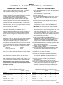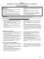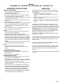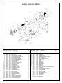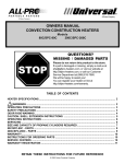
1
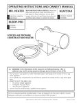
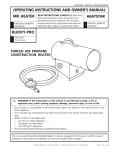
OWNERS MANUAL
FORCED AIR PROPANE CONSTRUCTION HEATERS
Models
30-FAS/SPC-30, 55-F/SPC-55, 85-FAC/SPC-85, 125-F/SPC-125
QUESTIONS?
MISSING / DAMAGED PARTS
STOP
Please do not return this product to the store.
If a part is damaged or missing, simply e-mail us at
[email protected], or visit our website at
http://allpro-heaters.com, or call our Customer
Service Department at (888) 619-7060.
We will be happy to assist you!
You can register your heater on line at
http://allpro-heaters.com/warranty.
TABLE OF CONTENTS
HEATER SPECIFICATIONS................................................................................................................ 2
WARNINGS .................................................................................................................................. 2
OPERATING PRECAUTIONS ............................................................................................................. 3
SAFETY PRECAUTIONS .................................................................................................................... 3
ODOR FADE WARNING ...................................................................................................................... 4
OPERATING INSTRUCTIONS ............................................................................................................ 5
SERVICING ......................................................................................................................................... 5
SIZE AND CAPACITY OF PROPANE CYLINDERS REQUIRED ........................................................ 6
WIRING DIAGRAMS. ........................................................................................................................... 7
30-FAS / SPC-30 - PARTS ................................................................................................................... 8
55-F / SPC-55 - PARTS ....................................................................................................................... 9
85-FAC / SPC-85 - PARTS ................................................................................................................ 10
125-F / SPC-125 - PARTS .................................................................................................................. 11
WARRANTY ....................................................................................................................................... 12
SERVICE CENTERS ........................................................................................................................ 12
INSTRUCTIONS FOR ORDING PARTS ........................................................................................... 12
WARRANTY REGISTRATION ........................................................................................................... 13
RETAIN THESE INSTRUCTIONS FOR FUTURE REFERENCE
© 2002 Scheu Products Company
Models
30-FAS/SPC-30, 55-F/SPC-55, 85-FAC/SPC-85, 125-F/SPC-125
HEATER SPECIFICATIONS
Type of Gas:
Gas Supply Pressure
to regulator
regulator out
Electrical Input:
Ignition:
Primary Flame Control:
High Temperature Control:
Model:
Rating:
For use with Propane Only
Maximum: Bottle Pressure
Minimum: 5 psig (34.5 kPa)
28" W.C. (6.97 kPa) (11" W.C. (2.74 kPa) for 30-FAS/SPC-30
115V, 60 Hz, 1Ø, 3a
Minimum Operating Voltage: 100V
Direct Spark (manually operated for 30-FAS/SPC-30 heaters)
Thermocouple Operated Gas Valve
240°F (116°C)
Minimum Ambient Temp. Rating
0°F (-17.8°C)
30-FAS / SPC-30
30,000 Btu/hr
Fuel Consumption:
Fuel Orifice Port No.:
Fuel Orifice Port Size:
Heated Air Output:
Average Air Temp. Rise:
(8.8 KW)
1.4 lbs/hr
(.64 kg/hr)
1
0.0730"
(1.854mm)
140cfm
(3.96 cmm)
250°F (139°C)
55-F/SPC-55
30,000-55,000
Btu/hr
(8.8-16.1 kw)
1.4-2.5 lbs/hr
(.64-1.1 kg/hr)
18
0.0196"
(0.50mm)
300cfm
(8.49cmm)
200°F
85-FAC / SPC-85
50,000 – 85,000
Btu/hr
(14.6 – 25.0 kW)
2.3 – 3.9 lbs/hr
(1.04 – 1.77 kg/hr)
18
0.0240”
(0.6024mm)
350 cfm
(9.91 cmm)
200°F (111°C)
125-F / SPC-125
75,000 – 125,000
Btu/hr
(21.9 – 36.6 kW)
3.5 – 5.8 lbs/hr
(1.59 – 2.63 kg/hr)
18
0.0295"
(0.75mm)
350 cfm
(9.91 cmm)
400°F (232°C)
WARNINGS
YOUR SAFETY IS IMPORTANT TO YOU AND TO OTHERS, SO PLEASE
READ THESE INSTRUCTIONS BEFORE YOU OPERATE THIS HEATER.
GENERAL HAZARD WARNING:
FAILURE TO COMPLY WITH THE PRECAUTIONS AND INSTRUCTIONS PROVIDED WITH THIS HEATER, CAN RESULT IN
DEATH, SERIOUS BODILY INJURY AND PROPERTY LOSS OR DAMAGE FROM HAZARDS OF FIRE, EXPLOSION, BURN,
ASPHYXIATION, CARBON MONOXIDE POISONING, AND/OR ELECTRICAL SHOCK.
ONLY PERSONS WHO CAN UNDERSTAND AND FOLLOW THE INSTRUCTIONS SHOULD USE OR SERVICE THIS HEATER.
IF YOU NEED ASSISTANCE OR HEATER INFORMATION SUCH AS AN INSTRUCTIONS MANUAL, LABELS, ETC. CONTACT
THE MANUFACTURER.
WARNING: NOT FOR HOME OR RECREATIONAL VEHICLE USE
WARNING: FIRE, BURN, INHALATION, AND EXPLOSION HAZARD. KEEP SOLID COMBUSTIBLES, SUCH AS
BUILDING MATERIALS, PAPER OR CARDBOARD, A SAFE DISTANCE AWAY FROM THE HEATER AS RECOMMENDED
BY THE INSTRUCTIONS NEVER USE THE HEATER IN SPACES WHICH DO OR MAY CONTAIN VOLATILE OR AIRBORNE
COMBUSTIBLES, OR PRODUCTS SUCH AS GASOLINE, SOLVENTS, PAINT THINNER, DUST PARTICLES OR UNKNOWN
CHEMICALS.
Scheu Products Company, Incorporated
Mail: P.O. Box 250, Upland, CA 91785
Plant: 8855 Baker Ave., Rancho Cucamonga, CA 91730
Telephone: 800-325-7057
www.scheuco.com
[email protected]
ANSI Z83.7/CGA 2.14-2000
8784
September 2003
Page -2-
Models
30-FAS/SPC-30, 55-F/SPC-55, 85-FAC/SPC-85, 125-F/SPC-125
OPERATING PRECAUTIONS
This is a propane, direct-fired, forced air heater. It's intended
use is primarily temporary heating of buildings under
construction, alteration or repair.
SAFETY PRECAUTIONS
When the heater is to be operated in the presence of other
people the user is responsible for properly acquainting those
present with the safety precautions and instructions, and of
the hazards involved.
1. Check the heater thoroughly for damage. DO NOT operate a
damaged heater.
2. DO NOT modify the heater or operate a heater which has
been modified from its original condition.
3. Use only propane gas.
4. Use only VAPOR WITHDRAWAL propane supply. If there is
any question about vapor withdrawal, ask your propane
dealer.
5. Mount the propane cylinders vertically (shutoff valve up).
Secure them from falling or being knocked over and protect
them from damage.
6. Locate propane containers at least (USA) 7 ft. (2.13m),
(Canada) 10 ft. (3m) from the heater and do not direct
exhaust toward containers.
7. IMPORTANT Use only the hose and regulator assembly
provided with the heater. Match the color stripe on the
hangtag attached to the hose assembly with the color on the
label located near the propane inlet fitting on the heater.
Inspect hose assembly before each use of the heater. If
there is excessive abrasion or wear, or hose is cut, replace
with hose assembly listed on parts list before using heater.
8. For indoor use only. Area must be well ventilated. Figure 1.
(also see "Operating Precautions").
9. If at any time gas odor is detected, IMMEDIATELY
DISCONTINUE operation until the source of gas has been
located and corrected. Read enclosed Odor fade and
Propane Sheet for additional information about detecting
propane leaks.
10. Install the heater such that it is not directly exposed to water
spray, rain and/or dripping water.
11. Maintain minimum clearance from normal combustible
material (like paper). Figure 2.
12. Due to the high surface and exhaust temperatures, adults
and children must observe clearances to avoid burns or
clothing ignition.
13. Operate only on a stable, level surface.
14. Do not use with duct work. Do not restrict inlet or exit.
15. Use only the electrical power specified. The electrical
connection and grounding must comply with National
Electrical Code - ANSI/NFPA 70 (USA) and CSA C22.1
Canadian Electrical Code, Part 1 (Canada).
16. Use only a properly grounded 3-prong receptacle or
extension cord.
17. Do not move, handle or service while hot or burning.
18. Use only in accordance with local codes or, in the absence
of local codes, with the Standard for the Storage and
Handling of Liquefied Petroleum Gases ANSI/NFPA 58 and
CSA B149.1, Natural Gas and Propane Installation Code.
Figure 1
VENTILATION: Minimum openings required
Opening
Opening
Heater
near floor near ceiling
Infrared ............................................................... 1 ft2 ..................... 1 ft2
Convection (25-VC) ........................................... 1 ft2 ..................... 1 ft2
Convection (All others) ...................................... 2 ft2 ..................... 2 ft2
Radiant ................................................................ 2 ft2 ..................... 2 ft2
Forced air (30, 55) ............................................. 1 ft2 ..................... 1 ft2
Forced air (85, 125, 170F) ................................. 2 ft2 ..................... 2 ft2
Forced air (3500-FACV, SPC-350) .................... 3 ft2 ..................... 3 ft2
Forced air (7000-FACV) .................................... 4 ft2 ..................... 4 ft2
Figure 2
MINIMUM CLEARANCE: From normal combustible material
Radiant
Forced Air
Clearance
Infrared
Convection Forced Air 7000-FACV
From floor ........................................................... 0 ft .............. 0 ft
From outlet .......................................................... 6 ft .............. 10 ft
From sides ................ 3 ft ............ 4 ft ............... 2 ft .............. 3 ft
From top ....................................... 6 ft ............... 3 ft .............. 5 ft
From front ................. 6 ft
From rear .................. 2 ft
Locate 10 ft. from canvas or plastic tarpaulins or similar coverings and
secure them to prevent flapping or movement due to wind action.
Propane is heavier than air. If propane leaks from a connection
or fitting, it sinks to the floor, collecting there with the
surrounding air, forming a potentially explosive mixture.
Obviously, propane leaks should be avoided, so set up the
propane supply with utmost care. Read enclosed Odor Fade
and Propane Sheet for additional information about detecting
propane leaks. Leak check new connections or reconnections
with a soap and water solution and follow all connection
instructions herein. Also, ask your propane dealer for advice on
the propane application and supply installation and ask him to
check it if there are any questions.
This heater was designed and certified for use as a
construction heater in accordance with ANSI Standard Z83.7/
CGA 2.14-2000. Check with your local fire safety authority if you
have any questions about your applications. Other standards
govern the use of fuel gases and heat producing products in
specific applications. Your local authority can advise you about
these.
Direct-Fired means that all of the combustion products enter the
heated space. Even though this heater operates very close to
100 percent combustion efficiency, it still produces small
amounts of carbon monoxide. Carbon monoxide (called CO) is
toxic. We can tolerate small amounts but not a lot. CO can build
up in a heated space and failure to provide adequate ventilation
could result in death. The symptoms of inadequate ventilation
are:
headache
dizziness
burning eyes and nose
nausea
dry mouth or sore throat
So, be sure to follow advice about ventilation in these operating
instructions.
Forced Air means that a blower or fan pushes the air through
the heater. Proper combustion depends upon this air flow;
therefore, the heater must not be revised, modified or operated
with parts removed or missing. Likewise, safety systems must
not be circumvented or modified in order to operate the heater.
Page -3-
Models
30-FAS/SPC-30, 55-F/SPC-55, 85-FAC/SPC-85, 125-F/SPC-125
ODOR FADE WARNING
WARNING
Asphyxiation Hazard
• Do not use this heater for heating human living quarters.
• Do not use in unventilated areas.
• The flow of combustion and ventilation air must not be
obstructed.
• Proper ventilation air must be provided to support the
combustion air requirements of the heater being used.
• Refer to the specification section of the heater’s manual,
heater dataplate, or contact the Scheu Products Company to
determine combustion air ventilation requirements of the
heater.
• Lack of proper ventilation air will lead to improper
combustion.
• Improper combustion can lead to carbon monoxide
poisoning leading to serious injury or death. Symptom of
carbon monoxide poisoning can include headaches
dizziness and difficulty in breathing.
FUEL GAS ODOR
LP gas and natural gas have man-made odorants added specifically for detection of fuel gas leaks.
If a gas leak occurs you should be able to smell the fuel gas. Since Propane (LP) is heavier than air you should smell for the gas
odor low to the floor. ANY GAS ODOR IS YOUR SIGNAL TO GO INTO IMMEDIATE ACTION!
• Do not take any action that could ignite the fuel gas. Do not
operate any electrical switches. Do not pull any power
supply or extension cords. Do not light matches or any other
source of flame. Do not use your telephone.
• Get everyone out of the building and away from the area
immediately.
• Close all propane (LP) gas tank or cylinder fuel supply
valves, or the main fuel supply valve located at the meter if
you use natural gas.
• Propane (LP) gas is heavier than air and may settle in low
ODOR FADING - NO ODOR DETECTED
• Some people cannot smell well. Some people cannot smell
the odor of the man-made chemical added to propane (LP)
or natural gas. You must determine if you can smell the
odorant in these fuel gases.
• Learn to recognize the odor of propane (LP) gas and natural
gas. Local propane (LP) gas dealers will be more than
happy to give you a scratch and sniff pamphlet. Use it to
become familiar with the fuel gas odor.
• Smoking can decrease your ability to smell. Being around
an odor for a period of time can affect your sensitivity to that
particular odor. Odors present in animal confinement
buildings can mask fuel gas odor.
ATTENTION - CRITICAL POINTS TO REMEMBER!
• Propane (LP) gas has a distinctive odor. Learn to recognize
these odors. (Reference Fuel Gas Odor and Odor Fading
sections above.
• Even If you are not property trained in the service and repair
of the heater, ALWAYS be consciously aware of the odors of
propane (LP) gas and natural gas.
• If you have not been properly trained in repair and service of
propane (LP) gas then do not attempt to light heater,
perform service or repairs, or make any adjustments to the
heater on the propane (LP) gas fuel system.
areas. When you have reason to suspect a propane leak,
keep out of all low areas.
• Use your neighbor’s phone and call your fuel gas supplier
and your fire department. Do not re-enter the building or
area.
• Stay out of the building and away from the area until
declared safe by the firefighters and your fuel gas supplier.
• FINALLY, let the fuel gas service person and the firefighters
check for escaped gas. Have them air out the building and
area before you return. Properly trained service people must
repair any leaks, check for further leakages, and then relight
the appliance for you.
• The odorant in propane (LP) gas and natural gas is
colorless and the intensity of its odor can fade under
some circumstances.
• If there is an underground leak, the movement of gas
through the soil can filter the odorant.
• Propane (LP) gas odor may differ in intensity at different
levels. Since Propane (LP) gas is heavier than air, there
may be more odor at lower levels.
• Always be sensitive to the slightest gas odor. If you
continue to detect any gas odor, no matter how small, treat it
as a serious leak. Immediately go into action as discussed
previously.
• A periodic sniff test around the heater or at the heater’s
joints; i.e. hose, connections, etc., is a good safety practice
under any conditions. If you smell even a small amount of
gas, CONTACT YOUR FUEL GAS SUPPLIER IMMEDIATELY.
DO NOT WAIT!
Page -4-
Models
30-FAS/SPC-30, 55-F/SPC-55, 85-FAC/SPC-85, 125-F/SPC-125
OPERATING INSTRUCTIONS
SERVICING
PREPARING FOR OPERATION
1. Check the heater for possible shipping damage. If any is
found, immediately notify the factory.
2. Follow all of the "Precautions".
3. Connect the POL fitting of hose and regulator assembly to
the propane cylinder by rotating the POL nut
counterclockwise into the propane cylinder's valve outlet and
securely tighten with a wrench.
4. Connect the hose to the heater by rotating the hose fitting
clockwise.
5. Securely tighten all gas connections.
6. Open the cylinder's gas valve and check all gas connections
with a soap and water solution. DO NOT USE A FLAME.
7. Connect power cord to well-grounded 115V, 60 Hz, 1Ø
source of power.
8. When using an extension cord, make certain that it is a 3wire (grounded) cord of proper wire size.
A hazardous condition may result if a heater is used that has
been modified or is not functioning properly. When the heater is
working properly:
* The flame is contained within the heater.
* The flame is essentially blue with perhaps some yellow
tipping.
* There is no strong disagreeable odor, eye burning or other
physical discomfort.
* There is no smoke or soot internal or external to the heater.
* There are no unplanned or unexplained shut downs of the
heater.
START
1. Before heater ignition, always allow heater fan (blower) to
run for 20 seconds to purge fuel.
2. Slowly open the main valve at propane cylinder.
3. Depress the fuel valve button to light the 55-F/SPC-55, 85FAC/SPC-85 and 125-F/SPC-125 models. On the 30-FAS/
SPC-30 also push the ignition button until the heater lights.
4. After the heater lights, keep the gas valve button depressed
for 15 seconds then release and the heater will continue to
operate.
5. Adjust burn rate with ball valve to desired setting (55-F/SPC55, 85-FAC/SPC-85 and 125-F/SPC-125 only).
STOP
1. Securely close valve on the propane cylinder.
2. Continue to operate heater until all fuel in the hose has
burned.
3. Unplug the power cord.
RESTART AFTER SAFETY SHUTDOWN
1. Securely close valve at propane cylinder. Unplug heater.
2. Wait 5 minutes.
3. Restart following "Start" procedure.
The parts lists and wiring diagram show the heater as it was
constructed. Do not use a heater which is different from that
shown. In this regard, use only the hose, regulator and cylinder
connection fitting (called a POL fitting) supplied with the heater.
IMPORTANT Match the color stripe on the hangtag attached to
the hose assembly with the color on the label located near the
propane inlet fitting on the heater. Do not use alternates. For
this heater, the regulator must be set as shown in
"specifications". If there is any uncertainty about the regulator
setting, have it checked.
A heater which is not working right must be repaired, but only by
a trained, experienced service person. To find the service center
closest to you, visit our website at www.scheuco.com.or call
(888) 619-7060.
You may also obtain in-warranty or out-of-warranty service by
taking the product to your local service center.
In-warranty products will be repaired with no charge for either
parts or labor. Please include a brief statement indicating date,
place of purchase, the nature of the problem and proof of
purchase.
Out-of-warranty products will be repaired with a charge for parts
and labor.
MAINTENANCE AND STORAGE
1. The heater should be inspected before each use, and at
least annually by a qualified person.
2. Before each use, check the soft "O" ring seat at the bullnose
of the POL fitting. If the "O" ring is cut, scuffed, or otherwise
damaged, replace it with part number 6681.
3. Turn off the gas at the LP-gas supply cylinder(s) when the
heater is not in use.
4. When the heater is to be stored indoors, the connection
between the LP-gas supply cylinder(s) and the heater must
be disconnected and the cylinder(s) removed from the
heater and stored out of doors and in accordance with
Chapter 5 of the standard for Storage and Handling of
Liquefied Petroleum Gases ANSI/NFPA 58 and CSA B149.1,
Natural Gas and Propane Installation Code.
Page -5-
Models
30-FAS/SPC-30, 55-F/SPC-55, 85-FAC/SPC-85, 125-F/SPC-125
SIZE AND CAPACITY OF PROPANE CYLINDERS REQUIRED
The charts below show the approximate size of the cylinder required for these heaters. To use the chart:
1.
2.
3.
Select the lowest air temperature expected (at the bottom of the chart).
Move straight up to time of operation desired (left side of chart).
Read the cylinder size required.
All heaters should have:
full cylinders
good air circulation
no frost on cylinders
AIR TEMPERATURE - oF (oC)
55,000 BTU/HR (16.1 kW)
MAXIMUM OPERATING TIME - HOURS
MAXIMUM OPERATING TIME - HOURS
30,000 BTU/HR (11.8 kW)
AIR TEMPERATURE - oF (oC)
125,000 BTU/HR (49.1 kW)
MAXIMUM OPERATING TIME - HOURS
MAXIMUM OPERATING TIME - HOURS
85,000 BTU/HR (33.4 kW)
AIR TEMPERATURE - oF (oC)
Use liquid
withdrawal
and a vaporizer
AIR TEMPERATURE - oF (oC)
Page -6-
Models
55-F/SPC-55, 85-FAC/SPC-85, 125-F/SPC-125
30-FAS/SPC-30,
WIRING DIAGRAMS
30-FAS/SPC-30
CONNECTION DIAGRAM
SCHEMATIC DIAGRAM
THERMOCOUPLE
B
ELECTRODE
MOTOR
B
IGNITION BUTTON
THERMOCOUPLE
RELAY
B
B** or O**
B
ELECTRODE
IGNITOR
1
L
W
L
B
N
2
G
MOTOR
W
IGNITION BUTTON
HIGH-LIMIT SWITCH
1
IGNITOR
N
B
R* or Y*
2
RELAY
115V
60HZ
HIGH-LIMIT SWITCH
GAS
VALVE
R* or Y*
B
W
G
LINE CORD
W
SPC-55
SPC-40, 85-FAC/SPC-85, 125-FAC/SPC-125
SCHEMATIC DIAGRAM
CONNECTION DIAGRAM
THERMOCOUPLE
B
SPARK PLUG
MOTOR
B
HIGH-LIMIT SWITCH
THERMOCOUPLE
RELAY
B** or O**
B
B
SPARK PLUG
IGNITOR
I1
W
I1
I2
W
MOTOR
IGNITOR
I2
B
R* or Y*
HIGH-LIMIT SWITCH
RELAY
115V
60HZ
GAS
VALVE
R* or Y*
LINE CORD
COLOR CODE
B BLACK R RED
Y YEL
BL BLUE
W WHITE O ORG
G GREEN
G
B
W
LEGEND
FEMALE CONN.
RING CONN.
TERMINAL BOARD
NOTE:
IF ANY ORIGINAL WIRING AS SUPPLIED WITH THE HEATER MUST BE REPLACED, IT MUS BE REPLACED WITH
TYPE AWG 105° C WIRE OR ITS EQUIVALENT EXCEPT AS INDICATED (*TYPE SF 2-200, **SGI-250°C)
WIRING CHART
30-FAS/SPC-30
SPC-40, 85-FAC/SPC-85, 125-FAC/SPC-125
Part No
Color
Length
From
To
Part No Color
Length
From
To
1040
1040
1385
1110
1370
1370
1441
1442
1806
1806
Black
Black
White
Green
Red
Red
Black
White
Orange
Orange
6" (152mm)
6" (152mm)
10" (253mm)
4 1/2" (114mm)
7" (177mm)
7" (177mm)
5" (127mm)
5" (127mm)
6" (152mm)
6" (152mm)
Ignition Switch
Ignition Switch
N (Ignitor)
2 (Ignitor)
High Limit
High Limit
Relay
Relay
Relay
Relay
T.B. Line
L (Ignitor)
T.B. Return
Ground
T.B. Middle
T.B. Line
T.B. Middle
T.B. Return
Thermocouple Junction Block
Thermocouple Junction Block
1040
1070
1041
1044
1044
1441
1442
1806
1806
6" (152mm)
11" (279mm)
4 1/2" (114mm)
16" (406mm)
16" (406mm)
5" ((127mm)
5" (127mm)
6" (152mm)
6" (152mm)
I1 (Ignitor)
1 (Ignitor
I2(Ignitor)
High Limit
High Limit
Relay
Relay
Relay
Relay
T.B. Line
Spark Plug
T.B. Return
T.B. Middle
T.B. Line
T.B. Middle
T.B. Return
Thermocouple Junction Block
Thermocouple Junction Block
Black
Orange
White
Yellow
Yellow
Black
White
Orange
Orange
Page -7-
30-FAS / SPC-30 - PARTS
Item 30-FAS SPC-30
1
2
3
4
*
6
7
8
9
10
11
12
13
16
17
18
19
20
21
22
24
27
30
31
32
33
Description
Qty.
3455
3392
3393
6825
3486
3367
3369
6825
Front Cover, Housing
Housing, 30-FAS
Rear Cover, Housing
Foil AL 2-3 Adhesive Back
1
1
1
1
6803
1368
3371
3372
1440
6730
1455
6732
1345
7285
6138
6144
6142
6133
1640
1377
1036
6223
6641
1811
3480
6803
1368
3371
3372
1440
6730
1455
6732
1345
7285
6138
6144
6142
6133
1640
1377
1036
6223
6641
1811
3480
Thermocouple, 15" w/Junction Block
Motor Assembly
Motor Mounting Plate
Blower Exit Bracket
High Limit Control Assembly
Blower Inlet Ring
Blower Housing
Blower 3.75 in. ccw 1/4" HUB
Flame Holder Assembly
Thermoelectric Valve
Fitting, Male Elbow
Fitting, Male Connector
Fitting, Elbow
Fitting, Coupling
Fuel Tube Assembly
Electrode Assembly
Power Cord Assembly
Strain Relief Bushing
Terminal Board
Relay Assembly
Base
1
1
1
1
1
1
1
1
1
1
1
1
1
1
1
1
1
1
1
1
Item 30-FAS SPC-30
34
35
*
37
38
*
*
*
42
43
44
45
46
47
48
*
*
*
*
*
*
*
*
*
Description
Qty.
3478
3517
6070
7095
6250
3478
3517
6070
7095
6250
Burner Box
Blower/Burner Bracket
Loop Clamp, 5/16"
Handle
Spark Ignitor, 115V
1
1
1
1
1
6811
7008
7152
6433
6255
7094
6712
6171
3667
7491
6373
6374
6916
7013
7061
8784
7009
1502
6811
7008
7152
6433
6255
7094
6712
6171
3667
7491
6373
6374
6938
7013
7061
8784
7009
1502
Label, Model, Operating Instructions
Label, Wiring
Hose Assembly, LP 1/4"
POL Excess Flow
Regulator 11" W.C.
Clip, Handle
Label, Hangtag, LP Hose
Switch, Push Button
Relay Mounting Bracket, 30-FAS
Label, Fuel/Ignition
Label, Fan Rotation
Label, Electrical Ground
Label, Logo
Label, Warning, Exit
Label, BTU
Manual, Operating Instructions
Parts List/Wiring Diagram
Hose & Regulator Assembly
1
1
1
1
1
2
1
1
1
1
1
1
1
1
1
1
1
1
* Not shown on exploded view
Page -8-
55-F / SPC-55 - PARTS
Item 55-F SPC-55 Description
1
2
3
4
5
6
7
8
9
10
11
12
13
14
*
16
17
18
19
20
21
22
23
24
25
26
6152
6257
6433
3955
1036
6223
1904
3275
6127
6133
6265
7285
6641
7431
6189
1811
3141
1935
1654
3676
1652
6086
2245
7094
7095
6225
6152
6257
6433
3955
1036
6223
1904
3275
6127
6133
6265
7285
6641
7431
6189
1811
3141
1935
1654
3676
1652
6086
2246
7094
7095
6225
Hose Assy, LP
Regulator 28" WC
POL Excess Flow 1/4 MPT
Panel, Bottom
Power Cord Assy
Strain Relief Bushing
Control Box Assy
Ignitor HYLO 801
Ftg, Male Connector
Ftg, Coupling
Ftg, Elbow Street
Thermoelectric Valve
Terminal Board
Ball Valve
Terminal "Y"
Relay Assembly
Ftg., Female Connector
Fuel Tube Assy
Motor Grille Assy
Brkt, Motor Mounting
Motor Assy
Fan, 7"
Outer Cylinder
Clip Handle Mounting
Handle
Snap Bushing, 5/8
Qty. Item 55-F SPC-55
1
1
1
1
1
1
1
1
1
2
2
1
1
1
2
1
1
1
1
1
1
1
1
2
1
1
Description
27 6226
6226 Universal Bushing
28 6224
6224 Snap Bushing, 1/2
29 6654
6654 Thermocouple 13" Lg w/J.B.
30 1082
1082 Spark Plug
31 3037
3037 Spark Plug Nut
32 6121
6121 Ftg, Male Elbow
33 3038
3038 Orifice Nut Mtg
34 1751
1751 High Limit Control Assy
35 2236
2236 Orifice Assy, LP
36 1651
1651 Middle Cylinder Assy
37 1931
1931 Flame Holder Assy
* 8784
8784 Manual, Operating Instructions/Parts List
* 8633
8633 Label, Model
* 7783
7783 Label, Operating Instructions
* 7781
7781 Label, BTU Rating
* 6374
6374 Label, Electrical Grounding
* 7651
7651 Label, Fuel
* 7503
7503 Label, Wiring Diagram
* 6383
8362 Label, Logo
* 6373
6373 Label, Fan Rotation
* 1667
1667 Hose & Regulator Assembly
* 8203
8203 Label Hang Tag, LP
* 7709
7709 Label , Fuel
* 7704
7704 Label Warning
*Not shown on exploded view
Qty.
1
1
1
1
2
1
1
1
1
1
1
1
1
1
2
1
1
1
2
1
1
1
1
1
Page -9-
85-FAC / SPC-85 - PARTS
Item SPC-85 85-FAC
1
2
3
4
5
6
7
8
9
10
11
12
13
14
15
16
17
18
19
20
21
22
23
24
25
1670
6086
1551
1671
1750
1674
3038
7433
6654
1751
1083
3037
1673
1752A
3044
6641
3275
1668
6133
3787
6127
7285
7404
7405
3690
1730
6086
1551
1671
1750
1674
3038
7433
6654
1751
1083
3037
1673
1752A
3044
6641
3275
1668
6133
3787
6127
7285
7404
7405
3690
Description
Cylinder, Outer Assembly
Fan, 7 inch
Motor Assembly, 80-FAS
Grille, Motor Mtg./Inlet Assy. 85
Flame Holder Assembly
Cylinder, Middle Assembly
Nut, Orifice Mounting 3/4-16
Fitting, Male Elbow
Thermocouple
High Limit Control Assembly
Spark Plug, 1/8 Gap
Nut-Spark Plug
Orifice Assembly
Control Box Assembly
Ignition Relay Bracket
Terminal Board
Spark Ignition, 115V
Fuel Tube Assembly
Fitting, Coupling
Spacer, TC Bracket
Fitting, Male Connector
TE Valve
Ball Valve, Variable Rate
Fitting, Female Connector
Control Panel Assembly
Qty.
1
1
1
1
1
1
1
1
1
1
1
3
1
1
1
1
1
1
1
1
1
1
1
1
1
Item SPC-85 85FAC
26
27
28
29
30
31
32
33
34
35
36
37
38
*
*
*
*
*
*
*
*
*
6223
1036
6152
6257
6433
7094
7095
1811
8362
7503
6265
3036
3775
8784
8507
8508
7432
6374
7709
8203
7704
6373
6223
1036
6152
6257
6433
7094
7095
1811
6383
7503
6265
3036
3775
8784
8507
8508
7432
6374
7709
8203
7704
6373
Description
Strain Relief Bushing
Power Cord
Hose Assembly
Regulator, 28" W.C. (6.97 kPa)
POL Excess Flow
Clip Handle Mounting, 3 pcs.
Handle, 3 pcs
Relay
Label, Logo
Label, Wiring
Fitting, Elbow
Bracket, TC
Side Panel
Manual, Operating Instructions/Parts List
Label, Model
Label, Operating Instructions
Label, BTU Rating
Label, Electrical Grounding
Label, Fuel Ignition
Label, Hang Tag, LP
Label, Warning
Label, Fan
Qty.
1
1
1
1
1
2
1
1
2
1
2
1
1
1
1
1
2
1
1
1
1
1
*Not shown on exploded view
Page -10-
125-F / SPC-125 - PARTS
Item SPC-125 125-F
1
2
3
4
5
6
7
8
9
10
11
12
13
14
15
16
17
18
19
20
21
22
23
24
25
26
27
1671
1551
7898
1998
7095
7094
7433
1083
2003
3036
3787
2002
2001
3037
2004
3038
1668
6654
3044
6641
6065
1811
3275
6079
6265
7897
7405
1671
1551
7898
1999
7095
7094
7433
1083
2003
3036
3787
2002
2001
3037
2004
3038
1668
6654
3044
6641
6065
1811
3275
6079
6265
7897
7405
Description
Grille Assembly
Motor Assembly
Fan, 8" (203.2mm)
Cylinder, Outer Shell Assembly
Handle
Clip Handle Mounting
Fitting, Male Elbow
Spark Plug, 1/8 (3.18mm) Gap
Control, High Limit Switch Assy.
Bracket, Thermocouple
Spacer, Thermocouple
Orifice, LP Assembly
Cylinder, Middle Assembly
Nut, Spark Plug
Flame Holder Assembly
Nut, Orifice Mounting
Fuel Tube Assembly
Thermocouple
Bracket Ignition Relay
Terminal Board
Spacer, Steel
Relay Assembly
Ignitor, Hi-Lo 801 Mini
Spacer, PC Standoff Nylon
Fitting, Elbow Street
Ball Valve, Variable Rate
Fitting, Female Connector
Qty.
1
1
1
1
1
2
1
1
1
1
1
1
1
3
1
1
1
1
1
1
1
1
1
3
2
1
1
Item SPC-125 125-F
28
29
30
31
32
33
34
35
36
37
38
39
40
*
*
*
*
*
*
*
*
*
*
*
6227
7158
6133
6127
7285
6223
1036
6433
6257
6152
4019
7843
2005
6374
6373
8362
8784
7709
8371
7503
8510
8653
8203
7704
6227
7158
6133
6127
7285
6223
1036
6433
6257
6152
4019
7843
2005
6374
6373
6383
8784
7709
8371
7503
8510
8653
8203
7704
Description
Snap Bushing, 1 1/4 Nylon
Snap Bushing, 3/4 Nylon
Fitting, Coupling
Fitting, Male Connector
Valve, Thermoelectric
Bushing, Strain Relief
Power Cord
POL Excess Flow (6.97 kPa)
Regulator, 28" W.C.
Hose Assembly, LP
Bottom Control Box
Washer, Flat
Control Box Assembly
Label, Electrical Ground
Label, Fan
Label, Logo
Label, Operating Instructions
Label, Ignition/Fuel
Label, BTU Rating
Label, Wiring
Label, Model
Manual, Operating Instructions/Parts List
Label, Hang Tag, LP
Label, Warning
Qty.
1
1
1
1
1
1
1
1
1
2
1
1
1
1
1
2
1
1
2
1
1
1
1
1
*Not shown on exploded view
Page -11-
Models
30-FAS/SPC-30, 55-F/SPC-55, 85-FAC/SPC-85, 125-F/SPC-125
WARRANTY
We are pleased that you have selected our product and take
this opportunity to assure you that qualified service facilities are
available if required. With the cooperation of independent
dealers, a nationwide network of authorized servicing dealers is
available for your servicing requirements.
Should your product require servicing, read the section of the
manual entitled “Servicing”.
Who gets the warranty? The warranty is limited to the consumer
who originally purchases the product.
What is covered? This limited warranty covers all imperfections
in workmanship and material.
What is not covered? This limited warranty does not cover
damage resulting from accident, misuse or abuse, lack of
proper maintenance, affixing of any attachments not provided
with the products, or loss of parts. IN NO EVENT SHALL
SCHEU PRODUCTS COMPANY BE LIABLE FOR ANY SPECIAL,
INCIDENTAL OR CONSEQUENTIAL DAMAGES NOR FOR ANY
DAMAGES RESULTING FROM MISUSE OR MODIFICATION OF
THIS PRODUCT.
Registering this heater within 10 days of date of purchase
ensures the buyer the protection as stated on our limited
warranty form.
LIMITED WARRANTY
The company warrants this product to be free from
imperfections in material or workmanship, under normal and
proper use in accordance with instructions of The Company, for
a period of one year from the date of delivery to the buyer. The
Company, at its option, will repair or replace (f.o.b. factory,
California) products returned by the buyer to the factory,
California, transportation prepaid within said one year period
and found by the Company to have imperfections in material or
workmanship.
the like and no implied warranty arising from course of dealing
or usage of trade. This warranty will not apply to any product
which has been repaired or altered outside of the California
factory in any respect which in our judgment affects its condition
or operation.
Some states do not allow the exclusion or limitation of
incidental or consequential damages, so the above limitation or
exclusion may not apply to you. This Warranty gives you specific
legal rights, and you may have other rights which vary from state
to state.
SERVICE CENTERS
Scheu Products Company has over 1,000 service centers
throughout North America. Call (888) 619-7060 or e-mail
[email protected] to request the service center nearest you.
Include the Make and model of your heater in any e-mails.
INSTRUCTIONS FOR ORDING PARTS
We recommend that only parts supplied by the manufacturer be
used on this unit. A locally purchased part may appear to be
identical, although in reality it might endanger the heater or the
persons operating the heater.
The heater should be serviced only by a trained, experienced
service person.
Read the section on "Servicing" before ordering parts.
For parts orders, call 888-619-7060 or e-mail us at
[email protected]. Please have the model number of your
heater and the replacement part number when placing your
order.
If a part is damaged or missing, simply e-mail us at
[email protected], visit our website at scheuco.com, or call
our Technical Support Department at (888) 619-7060.
Address any Warranty Claims to the Customer Service
Department, Scheu Products Company, Incorporated, P.O. Box
250, Upland, California 91785, or e-mail us at
[email protected]. Include your name, address and telephone
number and include details concerning the claim. Also, supply
us with the purchase date and the name and address of the
dealer from whom you purchased our product.
The foregoing is the full extent of the responsibility of the
Company. There are no other warranties, express or implied.
Specifically there is no warranty of fitness for a particular
purpose and there is no warranty of merchantability. In no event
shall the Company be liable for delay caused by imperfections,
for consequential damages, or for any charges of the expense
of any nature incurred without its written consent. The cost of
repair or replacement shall be the exclusive remedy for any
breach of warranty. There is no warranty against infringement of
Page -12-
Hand print only. Use black or blue ink pen to fill in this form. Cross or check inside the circle.
Warranty Registration
Your Information
First Name
Last name
Mailing Address
State
City
Postal code
E-mail Address
Annual house hold income before tax
Age of Purchaser
<$9,999
<20 years
$10,000 to $19,999
20-29 years
30-39 years
$20,000 to $34,999
40-49 years
$20,000 to $34,999
50-59 years
>$50,000
>60 years
Fold Here
Your Preferences
In choosing your heater the following categories
were:
Who selected the heater?
Male
Heater will be used by?
Individual
Business
How did you learn
about our heater?
Advertising
Relative/friend
Features
Store display
Previously owned heater
Portability
Female
Both
Somewhat
Important
Sudden cold weather
Emergency backup heat
Quality
Replaces old model
Hard to heat location
Heat Output
Heater on sale
Other
Warranty
Construction project
Where will you use the
heater?
Very
Important
Price
Other
What prompted you to
buy your heater?
Important
Serviceability
Construction site
Warehouse
Fuel economy
Shop
Patio
Ease of use
Size
Other
Fold Here
Product Information
/
-
/
Date of Purchase (MM/DD/YY)
Brand Name
Cost of Heater ($)
S/N (Located on a silver label on heater)
All Pro
Universal
Model Number (Located on a black and white label on heater)
National Riverside
Store Information where heater was purchased
Store Name
Type of Store
State
City
Hardware
Home Center
Warehouse Retailer
Discount Store
Farm Supply
Contractor’s Supply
Registering this heater within 10 days of purchase ensures the buyer the protection as stated on our limited warranty form.
Other
SCHEU PRODUCTS COMPANY, INC
ATTN: MARKETING DEPARTMENT
8855 BAKER AVENUE
RANCHO CUCAMONGA, CA 91730
Visit our website for product information, technical support, customer service, and warranty registration at:
WWW.ALLPRO-HEATERS.COM for All-Pro products or WWW.UNVERISAL-HEATERS.COM for Universal products.