1
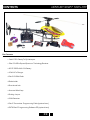
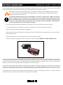
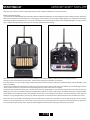
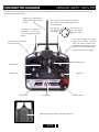
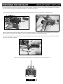
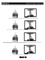
Specifications
Main Rotor Blades.............................................................................................................................520mm
Tail Rotor Diameter...............................................................................................................................21cm
Length..................................................................................................................................................105cm
Height..............................................................................................................................................34.4cm
Weight.................................................................................................................................................1.56kg
Speed Control............................................................................................................................75/95 Amp
Motor............................................................................................................................................1440kV
Battery...............................................................................................................................4S Li-Po 20C/30C
Pinion.......................................................................................................................................................10 tooth
Head Speed.....................................................................................................................1600 - 2100 RPM
Radio System........................................................................................................Elite 2.4GHz 6 Channel
Charger.........................................................................................................Standard AC Wall Charger
Century Helicopter Products
Designed and Developed in USA
1st Edition August 2008 All rights reserved.
CENTURY SWIFT 100% RTF
CONTENTS
INTRODUCTION
The Swift 100% Ready-to-Fly is a R/C helicopter system that is designed to offer beginner to intermediate helicopter pilots a 100% readyto-fly experience like no other. It comes 100% factory built, tested, and flown so you can get flying right away. It is equipped with the latest
state-of-the-art technology such as brushless outrunner motor and Lithium-Polymer power, a heading lock gyro, servos and CCPM control.
From smooth hovering to 3D aerobatics, the Swift 100% RTF’s larger size and powerful performance allow it to be flown outdoors in
conditions that would typically ground smaller mid. and micro sized helicopters.
In addition to its impressive features list and performance, the Swift 100% RTF is the first true ready-to-fly full size electric helicopter available on the market and it comes equipped with the Elite 6-channel 2.4GHz Spread Spectrum Technology radio system. Unlike traditional
72MHz radios, the Elite 6 SST provides freedom from frequency restrictions and interference. The Elite 6 SST radio offers other unique
advantages like faster control responses and innovative features allowing the beginner pilot to get started while the more advanced pilot
can program the radio through a computer interface for more extreme 3D aerobatics . The system also includes the feather light Elite
6 SST receiver. The following are features of the Elite 6 2.4GHz Spread Spectrum Technology radio. *Programming is available via the
optional programming interface
• Full-range capability
• Infinite Model Memory (Based on storage capacity of your computer)
• Heli and airplane programming
• Standard or 120º CCPM swashplate mixing
• 3-axis dual rates and exponential
• Travel adjust
• Sub trim
• Two 5-point throttle curves
• Two 5-point pitch curves
• Revo mixing
• Gyro sensitivity programming
• Two programmable mixes
The Elite 6 is not only perfectly suited for the Swift 100% RTF it can also be used to fly just about any size and type of model due to its
full-range and programming capabilities. And although the Swift 100% RTF is nearly ready-to-fly right from the box, please take the time
to read through this manual for tips on battery safety and charging, control checks, adjustments and more before attempting your first
flight.
Warning
This radio controlled model is not a toy! It is a precision machine requiring proper assembly and setup to avoid accidents. It is the responsibility of the owner to operate this product in a safe manner as it can inflict serious injury otherwise. It is recommended that if you
are in doubt of your abilities, seek assistance from experienced radio control modelers and associations. Keep loose items that can get
entangled in the rotor blades away for the main and tail blades, including loose clothing, hair, or other objects such as pencils and screwdrivers. Especially keep your hands away from the rotor blades. As manufacturer, we assume no liability for the use of this product.
Warranty Period
Century Helicopter Products warranties that the Products purchased (the “Product”) will be free from defects in materials and workmanship at the date of purchase by the Purchaser.
Limited Warranty
(a) This warranty is limited to the original customer (“Purchaser”) and is not transferable. REPAIR OR REPLACEMENT AS PROVIDED
UNDER THIS WARRANTY IS THE EXCLUSIVE REMEDY OF THE PURCHASER. This warranty covers only those Products purchased
from an authorized Century Helicopter Products dealer. Third party transactions are not covered by this warranty. Proof of purchase is
required for warranty claims. Further, Century Helicopter Products reserves the right to change or modify this warranty without notice
and disclaims all other warranties, express or implied.
(b) Limitations- CENTURY HELICOPTER PRODUCT MAKES NO WARRANTY OR REPRESENTATION, EXPRESS OR IMPLIED, ABOUT NONINFRINGEMENT, MERCHANTABILITY OR FITNESS FOR A PARTICULAR PURPOSE OF THE PRODUCT. THE PURCHASER ACKNOWLEDGES THAT THEY ALONE HAVE DETERMINED THAT THE PRODUCT WILL SUITABLY MEET THE REQUIREMENTS OF THE PURCHASER’S
INTENDED USE.
(c) Purchaser Remedy- Century Helicopter Products’s sole obligation hereunder shall be that Century Helicopter Products will, at its
option, (i) repair or (ii) replace, any Product determined by Century Helicopter Products to be defective. In the event of a defect, these
are the Purchaser’s exclusive remedies. Century Helicopter Products reserves the right to inspect any and all equipment involved in
a warranty claim. Repair or replacement decisions are at the sole discretion of Century Helicopter Products. This warranty does not
cover cosmetic damage or damage due to acts of God, accident, misuse, abuse, negligence, commercial use, or modification of or to any
part of the Product. This warranty does not cover damage due to improper installation, operation, maintenance, or attempted repair by
anyone other than Century Helicopter Products. Return of any goods by Purchaser must be approved by Century Helicopter Products
before shipment.
P.1
CENTURY SWIFT 100% RTF
FLIGHT CHECKLIST
Please note this checklist is not intended to be a replacement for the content included in this instruction manual. Although it can
be used as a quick start guide, we strongly suggest reading through this manual completely before proceeding.
Remove and inspect contents
Begin charging the flight battery
Install the 8 included AA batteries in the transmitter
Install the flight battery in the helicopter (once it has been fully charged)
Test the controls
Familiarize yourself with the controls
Find a suitable area for flying
Flight Guidelines
Always turn the transmitter on first
Plug the flight battery into the electronic speed control (ESC)
Allow the ESC, gyro, and receiver to arm and initialize properly
Fly the model
Land the model
Unplug the flight battery from the ESC
Always turn the transmitter off last
P.2
CENTURY SWIFT 100% RTF
CONTENTS
*
*
Box Contents
• Swift 100% Ready To Fly Helicopter
• Elite 6 2.4GHz Spread Spectrum Technology Receiver
• 4S1P 3300mAH Li-Po Battery
• Elite 6 2.4GHz Radio
• Blade holder
• Assorted Allen Keys
• Binding Jumper
• Elite 6 Transmitter Programming Cable (optional item)
• CNTX Elite 6 Programming Software CD (optional item)
• 4 Cell Li-Po Charger
• Blue thread lock
• 8 AA Batteries
P.3
CENTURY SWIFT 100% RTF
BATTERY GUIDELINES
While the 4S 3300mAh Lithium Polymer Battery included with your Swift 100% RTF features Charge Protection Circuitry, you MUST
read the following safety instructions and warnings before handling, charging or using the Li-Po battery.
Note: Lithium Polymer batteries are significantly more volatile than the alkaline, NiCd or Ni-MH batteries used in RC
applications. All instructions and warnings must be followed exactly. Treat the Li-Po battery with respect. Mishandling of Li-Po batteries can result in fire.
!
It is extremely important that you cycle the Li-Po battery. To do this, on your first 5 to 7 flights, you must not
deplete the battery. Fly for a maximum of 3 to 4 minutes on your first few flights. After flying, wait 15 minutes
before charging the battery. This will ensure your battery to run at it’s maximum capacity and extend the life of
the battery. This is called cycling and must be done 5 to 7 times before performing full flights. If this guideline is
not properly followed, you may cause damage to the battery.
• You must charge the included 4-Cell 3300mAh Li-Po battery in a safe area away from flammable materials.
• It is recommended that you charge the Li-Po battery on a cement floor or within a metal pan in case of fire.
• Do not charge the battery when installed in the helicopter.
• Never charge the battery unattended. You should always monitor the battery during it charging cycle to react to any potential
problems that may arise.
• After flight, the battery must be cooled to ambient temperature before charging.
• Improper handling or charging could result in injury and/or property damage. DO NOT use a NiCd or Ni-MH charger.
• If at any time during the charge or discharge process the battery begins to balloon or swell, discontinue charging or discharging immediately. Quickly and safely disconnect the battery, then place it in a safe, open area away from flammable materials to observe it for at
least 15 minutes. Continuing to charge or discharge a battery that has begun to balloon or swell can result in a fire. A battery that has
ballooned or swollen even a small amount must be removed from service completely.
• Always take care when connecting the leads on the battery to the charger and to the ESC. Although the connectors forcibly provide only
one way to connect the plugs, make sure you are matching the Red (positive +), and Black (negative -) wires to each other. If at any time
the connector breaks and the wires separate from each other, never let the loose wires touch each other as this can result in a short.
• Depending on how much the battery has been drained, it takes about 1.5 hours to fully charge your battery. It is important that you
monitor the status of your battery and never leave a charging battery unattended.
P.4
BATTERY GUIDELINES
CENTURY SWIFT 100% RTF
• In the event of a crash, you must quickly and safely disconnect and remove the battery from the model, then place it in a safe, open area
away from flammable materials to observe it for at least 15 minutes.
• Always store the battery at room temperature and approximately ½ charge for best results.
• When transporting or temporarily storing the battery, the temperature range should be between 40 to 120 degrees Fahrenheit. Do
not store the battery or helicopter/transmitter in a car or direct sunlight whenever possible. If stored in a hot car, the battery can be
damaged or even catch fire.
• Do not over-discharge the battery. Discharging the battery too low can cause damage to the battery resulting in reduced performance
and duration.
• The battery provided offers balancing leads. The typically hooks up to a battery balancer during the charging cycle. Although not necessary, it is recommended to charge your battery with a battery balancer. This will prolong the life of the Li-Po battery.
The 75-amp brushless ESC installed in your Swift 100% RTF model features a “soft” low voltage cutoff (LVC) that occurs when the battery
reaches 14.4V under load. When the soft cut-off occurs, the ESC will automatically reduce power to the motor (regardless of the power
level you have set with the throttle stick/curve) in order to prevent the voltage of the battery from dropping to below 14.4V. After the
power is reduced and the voltage “rebounds” (rises) to above 14.4V, the ESC will automatically return power to the motor until the battery
reaches 14.4V again. This process will continue to repeat, sometimes causing the motor/power to “pulse” rapidly, helping to provide
a visual and/or audible indication of the low battery voltage. However, in some cases it may be difficult to detect pulsing of the motor/
power, so we suggest that you be extremely aware of the power level of the Li-Po battery during flight. If at any time the helicopter begins
to require more throttle than typical to maintain hover or flight, or has lost significant power, you must land the helicopter IMMEDIATELY
to prevent a sudden loss in power that could result in a crash.
Although the soft LVC of the ESC will help to prevent “deep” (below 9V; 3V per cell) over-discharge of the battery, it is not recommended
that you continue to run the motor for an extended length of time after landing and/or noticing a loss of power. Routinely discharging
the battery to 9V can still cause permanent damage to the battery, resulting in shortened flight times, loss of power output or failure of
the battery entirely.
It is important that you only charge the included 4S 3300mAh Li-Po Battery with the included charger or a comparable 4S Li-Po charger. Attempting to charge the battery using a charger not suited to charge at least a 4 cell Li-Po battery could result in serious damage.
Please familiarize yourself thoroughly with the Battery Warnings and Guidelines section before continuing. NEVER charge the battery
unattended.
Note:
The Li-Po battery included with your Swift 100% RTF will arrive partially charged. For this reason the initial charge may only take approximately 30-50 minutes.
If you have any further questions or concerns regarding charge error indications, please contact Century Helicopter Products at
(408)451-1155.
P.5
BATTERY WARNINGS & SAFETY
CENTURY SWIFT 100% RTF
Lithium Polymer Battery Safety
1.
2.
3.
4.
Never fast-charge any battery type unattended.
Never charge Li-Poly cells or battery packs at any rate unattended.
Only charge Li-Poly cells or battery packs with a charger designed specifically for lithium polymer chemistry.
Li-Poly cells can ignite because of unmatched cell capacity or voltage, cell damage, charger failure, incorrect charger setting and
other factors.
5.
Always use the correct charging voltage. Li-Poly cells or battery packs may ignite if connected to a charger supplying more than
5 volts per cell.
6.
Always assure the charger is working properly.
7.
Always charge Li-Poly cells or battery packs where no harm can result, no matter what happens. We suggest a brick box or
likeness. Have sand handy in a bucket for any need to extinguish any fire. NEVER use water on any cells or battery packs.
8.
Never charge a cell or battery pack in a model. A hot pack may ignite wood, foam, plastic, etc.
9.
Never charge a cell or battery pack inside a motor vehicle or in a vehicle’s engine compartment.
10. Never charge a cell or battery pack on a wooden workbench or on any flammable material.
11. If a cell or battery pack is involved in a crash:
a. Remove the cell or battery pack from model.
b. Carefully inspect the cell or battery pack for shorts in the wiring or connections. If in doubt, cut all wires from cell or battery
pack.
c.Disassemble the pack
d. Inspect cells for dents, cracks and splits. Dispose of damaged cells.
12. Dispose of cells or battery packs as follows:
a. Discharge: with the cells or battery pack in a safe area, connect a moderate resistance across the terminals until the cell or
battery pack is discharged. CAUTION: cell or battery pack may be hot.
b. Discard Li-Po batteries by puncturing the plastic envelope, immerse in salt water for several hours and place in regular trash.
13. Handle all cells or battery packs with care, as they can deliver high currents if shorted. Shorting by a wedding ring, for example,
will remove a finger.
14. Always store cells or battery packs in a secure location where they cannot be shorted or handled by children.
15. When constructing a battery pack, always use cells of the same capacity (mAh)
16. DO NOT store fully charged or discharged batteries in your helicopter.
17. When cutting wires, always cut ONLY ONE WIRE AT A TIME.
** Century Helicopter Products will not be liable for any damages that may occur to your helicopter due to any misuse or
mishandling as explained above.
** Century Helicopter Products, its successors, heirs and assignees are not responsible in way for any and all bodily injuries)
and/or property damage that may occur from the use of, or caused by in any way from Lithium Polymer battery packs offered by
and or distributed by Century Helicopter Products.
P.6
ESC GUIDELINES
CENTURY SWIFT 100% RTF
Your Electron ESC
The Electron ESC provided with your Swift 100% RTF is a full featured ESC. It is a revolutionary electric speed controller dedicated full
size R/C applications. The Electron is the result of years of research and development. The Electron has multiple, complex, yet easy to
program built-in functions, gentle to the gears and pilots can program the Electron in the field with ease and comfort.
Features / Specs:
• Features Easy to Use: 4 Flying Modes
• Supports Quick Throttle Response
• Supports Linear Throttle Output
• Supports Stable RPM Control
• Supports Compatibility with Most Brushless Motors
• Supports High Speed Brushless Motors
• 2-Pole Brushless Motors up to 240,000rpm
PWM Frequency..........................................12Khz
BEC Continuous Output.............................. None
Continuous / 15-Sec Peak Current
CNE475................................................75A / 90A
• 6-Pole Brushless Motor up to 80,000rpm
• High Temperature Protection for ESC Body
• Ferrite Ring for Reduced Interference
• 12-Pole Brushless Motor up to 40,000rpm
• Built-in Heat Sink
• Built-in Throttle Calibration Function
• Built-in Soft Start Function for Helicopter
Maximum Operation Voltage / Li-Po Cell
CNE475.............................................14.V / 4-Cell
Physical hardware limitation 30V
Low Battery Protection
Soft Cut Voltage..................2.9V per Li-Po Cell
Hard Cut Voltage................2.6V per Li-Po Cell
• Built-in Governor Function for Helicopter
• Built-in Auto Motor Timing Function
• Built-in World Famous Brand MOSFET with High
Quality, Reliability & Low Impedance Two Stage
Protection Soft Cut then Hard Cut
• Low Battery Protection for LiPo/LiIon Battery
High Temperature Protection
Soft Cut Temperature...........110°C / 230°F
Hard Cut Temperature.........120°C / 248°F
(If CNE475 utilizes anything beyond 4
cell Li-Po or 14.8V, the power source
may cause serious damage to the ESC
and will not be covered under warranty)
Entering Programming mode:
Although the Swift 100% RTF comes pre-programmed, here is a guideline on how to change programming. Unless you plan on using this
ESC for another application, PLEASE DO NOT CHANGE THE SETTINGS OF YOUR ELECTRON ESC AS IT COMES PRE-PROGRAMMED. The
Electron software is easy to program. You can select 1) Soft start without governor 2) Soft start with Governor 3) Regular Fast start.
NO BRAKE 4) Regular fast start with Brake.
1.) Turn the transmitter on and move the throttle stick to the top position.
2.) Supply power to the Electron by connecting your battery. After roughly 2 seconds, the Electron will emit a series of tones indicating
entry into programming mode.
3.) Move the throttle stick to the lowest position and the Electron will ask which mode you want to use based on the number of beeps.
4.) Select a mode by moving the throttle to the top position.
5.) The Electron will verify that you have activated a mode by the number of beeps pertaining to the mode selected.
6.) Disconnect power source from the electron once the Electron is programmed.
7.) Move throttle stick down and you are ready to fly!
Using Programming mode:
Soft start (heli) w/o governor
MODE 1
Soft start (heli) with governor
MODE 2
1.) Throttle stick UP
2.) Connect battery (this will be followed by a series of tones indicating “programming mode”).
3.) Move throttle stick DOWN.
4.) Wait for ONE BEEP.
5.) Move throttle stick UP confirming selection.
6.) Unplug battery and move throttle stick DOWN and reconnect battery to fly.
1.) Throttle stick UP
2.) Connect battery (this will be followed by a series of tones indicating “programming mode”).
3.) Move throttle stick DOWN.
4.) Wait for TWO BEEPS.
5.) Move throttle stick UP confirming selection.
6.) Unplug battery and move throttle stick DOWN and reconnect battery to fly.
Fast start (airplane) No brake 1.) Throttle stick UP
2.) Connect battery (this will be followed by a series of tones indicating “programming mode”).
3.) Move throttle stick DOWN.
MODE 3
4.) Wait for THREE BEEPS.
5.) Move throttle stick UP confirming selection.
6.) Unplug battery and move throttle stick DOWN and reconnect battery to fly.
Fast start (glider) with brake
MODE 4
1.) Throttle stick UP
2.) Connect battery (this will be followed by a series of tones indicating “programming mode”).
3.) Move throttle stick DOWN.
4.) Wait for FOUR BEEPS.
5.) Move throttle stick UP confirming selection.
6.) Unplug battery and move throttle stick DOWN and reconnect battery to fly.
P.7
ESC GUIDELINES
CENTURY SWIFT 100% RTF
Reversing the motor
The motor turning direction can be reversed at any time by revering the two red/black power wires connected to the motor. (DO NOT
REVERSE POLARITY FROM THE BATTERY CONNECTOR AT ANY TIME)
How it works
1.) Turn on your transmitter.
2.) Connect the main power to the Electron.
3.) You will hear 4 beeps once power is supplied to the Electron.
4.) The Electron will remain disarmed until the throttle stick is moved to the upright position (The Electron has an 8 second slow spool up
feature, this feature is a power saver and to prevent the motor from accidentally powering up).
The Electron 75 has a 30 second re-initialization function (in soft start modes only). This will be activated if the throttle is in the low position
for 30 seconds or more. This function will cause a “soft start” or slow increase in throttle no matter how quickly the throttle is moved.
Troubleshooting
Everything is hooked up correctly, the receiver & servos work, but throttle does not respond.
The Electron is not seeing “low stick” and is not arming. Try moving the throttle stick and trims to low positions until the speed control
arms. Observe any endpoint adjustments that may also relate to the throttle. The throttle channel may need to be reversed in the transmitter to allow the proper throttle response.
Every time when throttle is at maximum the ESC cuts off after a moment, even with new fully charged batteries.
Electron will turn off the motor if the battery voltage drops below the programmed voltage safeguard. This is to prevent unexpected and
erratic results. If the cutoff occurs on new fully charged batteries the motor may be drawing too much current from the battery. This will
cause the battery voltage to drop very rapidly and initiate the safeguard. The motor may be compromised in some way by too much resistance in the gearing or a prop or blades that are too large for the motor. The battery being used may not be capable of supplying enough
power to the motor. Try other batteries.
Nothing works!
Check all the connections to ensure correct polarity and power supply. Also check transmitter for any inhibitors. If there is nothing else
that can be done then call the dealer where you purchased the Electron or Century directly. Please refer to the warranty section.
P.8
CENTURY SWIFT 100% RTF
GYRO
Your Swift 100% RTF is equipped with a Century Basic PG3000 Heading Lock Gyro. It’s lightweight, size, and performance make this gyro
an excellent feature in the Swift 100% RTF package.
The following checklist includes the steps you must follow to ensure proper initialization and operation of the gyro:
After connecting the flight battery to the ESC, be sure that you do not move or sway the helicopter. Allow it to remain motionless until the
red LED on the gyro illuminates solidly, indicating that the gyro has initialized properly and is ready for use. Note: It is extremely important
that you do not move or sway the helicopter after powering it on and before the gyro initializes. The gyro must be allowed adequate time to
record the neutral position in order to initialize for proper operation. You must also not provide any transmitter input during the initialization process. If you start moving the rudder servo before the gyro has a chance to initialize, the gyro will not be able to find where “center”
is on the rudder servo thus providing improper rudder control. This will make the Swift 100% RTF appear to be out of control in flight. If
you accidentally move the helicopter or provide input from the transmitter after powering it on and before the gyro initializes, power the
helicopter off (by disconnecting the flight battery from the ESC) then repeat the process to power the helicopter on and to initialize the
gyro properly.
Once the gyro has initialized properly, the helicopter is ready for flight.
Before making your first flight, it will be necessary to confirm that the gyro is responding properly to the movements of the helicopter and
providing proper inputs to the tail servo in order to counteract any unwanted changes in yaw. To do this, view the servo arm (from the
top of the servo) and note the direction the arm rotates when you give a right rudder input on the transmitter (while the model remains
motionless). In the case of the Century ES110 servo installed on your Swift RTF model, the servo arm should rotate toward the front of
the helicopter. Then, yaw the nose of the helicopter quickly to the left, while again noting the direction the tail servo arm rotates. The arm
should rotate in the same direction as it did for a right rudder command (toward the front of the helicopter).
After confirming that the gyro is providing proper inputs to the tail servo, power off the helicopter and be sure to review the following sections of the manual BEFORE proceeding with the first flight.
Gyro Mode and Gain Adjustments:
• The Century Basic PG3000 offers a Dual Remote Gain Adjustment feature. This, along with the Elite 6’s Gyro Sensitivity feature, allows
the gyro mode (Standard Rate or Heading Lock) and gain values to be set remotely on the transmitter.
• The gain values for the gyro are adjusted on the transmitter itself. The VR (A) selection choice has been set to the Gyro (GYRO) switch,
the two available gain values can be selected using this knob during flight. When the VR(A) knob is turned counter-clockwise past the halfway point, the GYRO will enter into NORMAL mode. This is indicated on the Gyro with the LED light unlit. When the VR(A) knob is turned
clockwise past the half-way point, the Gyro will enter in to HEADING LOCK mode. This is indicated on the Gyro with a constant red LED light.
It is recommended to always fly in HEADING LOCK mode.
• During your first flight, establish a stable hover and apply some short and quick rudder inputs while observing the reaction of the tail when
the control stick is returned to its neutral position. If there is any tendency for the tail to twitch quickly (oscillate) from side to side, it will be
necessary to lower the Rate used for the selected Gyro switch position. The goal when adjusting the Rate for the Gyro knob position is to
find the highest Gyro gain value (Rate) at which the tail of the helicopter will not oscillate in nearly all areas of flight, including fast forward
flight and descents. You may need to increase the Gyro gain value when flying in windy conditions or you may need to decrease the Gyro
gain value in flight to prevent significant tail oscillation when performing certain maneuvers.
Trim Adjustments
• During flight, it may be necessary to make some small adjustments to the rudder trim in order to prevent the nose/tail of the model from
“drifting” to the left or right when the rudder stick is in the neutral position. Typically, only a small amount of adjustment may be necessary.
Note: It is always best to avoid sudden temperature and environmental condition changes when using a gyro. For example, it is best to not
fly a model on a very hot (or cold) day immediately after removing it from an air-conditioned (or heated) vehicle. It is also best to keep the
gyro out of direct sunlight and away from any heat-generating sources on the model. To help the gyro better acclimate to temperature
and environmental conditions at the flying field, it is best to let your Swift 100% RTF model stand for approximately 10–15 minutes before
flying, allowing the temperature of the gyro sensor to stabilize. If you do not allow the temperature to stabilize, you may experience radical
trim changes that require significant adjustments of the rudder trim during flight.
LED Reference Table
LED Indicator
LED On
LED Off
LED Blinking Fast
LED Blinking Slow
LED Blinking Twice
State of Gyro
Gyro has entered HEADING LOCK mode
Gyro is in NORMAL mode
Gyro was turned on under NORMAL mode and cannot be properly initialized.
Please turn the gyro’s sensitivity selection switch on the transmitter to LOCK mode, then switch
off the power of the receiver and switch on again.
The Gyro has failed to receive a signal from the rudder servo. Re-initialize the gyro by turning
the receiver’s power off and turn it back on.
The center point of the gyro has shifted. It needs to be re-initialized.
P.9
CENTURY SWIFT 100% RTF
STARTING UP
Note: If you do not hear a series of tones after battery power is applied, the ESC has not armed properly.
Please review the following:
1.) Install the 8 included AA batteries in the Elite 6-channel 2.4GHz Spread Spectrum Technology transmitter. Check the power level of the
batteries and operation of the transmitter by switching the power switch on (to the right). The LED lights on the transmitter will indicate
the voltage condition of the batteries. If at any time the voltage of the batteries falls to a point when the RED LED lights up it will be necessary to replace the batteries with new ones, use the recommended size and voltage.
2.) Confirm that the throttle stick is in the lowest possible position and that the throttle trim is set at the bottom position.
3.) Confirm that all connections are still intact. Check the wire going from the ESC to the receiver.
If the ESC will not arm after confirming the details listed above, contact Century Helicopter Products Support staff at 408-451-1155
before proceeding.
4.) Once you have placed the helicopter in a safe area, free of obstructions, and are clear of the rotor blades, you can safely begin to power
up the model to confirm proper operation and operating direction of the motor and rotor blades.
5.) Advance the throttle stick slowly, just until the motor and rotor blades begin to spin. Note the direction that the main and tail rotor
blades spin. The main rotor blades should spin clockwise when viewed from the top, and the tail rotor blades should spin counterclockwise
when viewed from the right-hand side of the helicopter. If both sets of rotor blades are operating in the wrong direction, power down the
helicopter, unplug the flight battery, then simply reverse the position of red and black wire lead connections from the ESC to the motor.
Note: If the main rotor blades are operating in the correct direction but the tail rotor blades are not, the belt driving the tail rotor may be
“twisted” in the wrong direction. To correct this, remove the tail rotor case and parts from the tail boom and pull the belt “straight” (so it
is horizontal and has no twists). Then, rotate the belt 90 degrees clockwise when viewing the helicopter from behind.
P.10
CENTURY SWIFT 100% RTF
TRANSMITTER DIAGRAM
From the box, the transmitter is set up as shown. All knobs and toggle switches can be programmed in the optional transmitter programming software and cable.
Make sure to install the antenna when using the transmitter.
This knob controls the gyro sensitvity.
The optimal stock position should be
around 4 o’clock.
This half puts
the gyro into
rate mode.
This knob will toggle the
headspeed. Turn it clockwise to increase the head
speed.
This half puts the
gyro into heading lock mode
This switch toggles the travel
length of your servos. Pushed
back, the servos provide more
gentle aileron and elevator. Pulled
forward, the servos provide more
responsive aileron and elevator.
This switch has no function
on stock settings.
Elevator trim
Throttle trim
Rudder trim
Aileron trim
Bind button
Throttle trim
USB Programming Cable or Simulator cable port.
P.11
Power switch
CENTURY SWIFT 100% RTF
PREPARING THE CHECKLIST
Use the hook and loop material for mounting the Li-Po battery located underneath the front tray, below the ESC (Electronic Speed Control) be sure that the battery wires align with the ESC wire. As show in the picture.
Once the battery has been properly positioned, fasten the hook and look strap around the battery for added security.
Although each Century Swift 100% RTF model is control tested at the factory, it is a good idea to test the controls prior to the first
flight to ensure none of the servos, linkages or other parts were damaged during shipping and handling.
Before proceeding, disconnect the three bullet connectors between the motor and ESC. It is not safe to perform the control test with
the motor connected to the ESC.
Lower the throttle/collective (left-hand) stick completely then turn the transmitter on.
P.12
CENTURY SWIFT 100% RTF
CONTROLS
Position the helicopter to view it from the left or right side. Move the left-hand stick up and down to check the collective pitch control.
Front of Helicopter
When the stick is pushed up, the swashplate should rise, increasing the pitch of the main blades.
Front of Helicopter
With the stick pulled back down, the swashplate should lower, decreasing the pitch of the main blades.
Front of Helicopter
Again viewing the helicopter from the left or right side, move the right-hand stick forward and aft to check elevator pitch control.
When the stick is pushed forward, the swashplate should also tilt forward.
Front of Helicopter
With the stick pulled back, the swashplate will tilt toward the rear.
P.13
CENTURY SWIFT 100% RTF
CONTROLS
While viewing the helicopter from the rear (tail boom toward you), move the right-hand stick left and right to check aileron roll control.
When the right-hand stick is pushed to the left, the swashplate should also tilt left.
With the right-hand stick pushed right, the swashplate will tilt to the right.
While viewing the helicopter from the rear (tail boom toward you), move the left-hand stick left and right to check rudder/tail rotor
pitch control. When the left-hand stick is pushed to the left, the tail pitch slider should move to the left.
With the left-hand stick pushed right, the tail pitch slider should move to the right.
P.14
CENTURY SWIFT 100% RTF
BINDING
When powering on and you find that you do not have control of the helicopter, it may be possible that you need to bind your transmitter
to the receiver in your heli. To do this, you must follow these steps:
1) Plug the binding jumper into the receiver on the helicopter
2) Connect the Li-Po batter to the ESC on the helicopter.
3) While holding down the bind button, turn on the transmitter.
4) Watch the RED flashing LED on the Signal Booster on the
right side of your heli. Wait for it to go from a flashing RED to a
solid RED. Once you see solid RED, the helicopter and transmitter are bound.
6) Pull the binding jumper from the receiver.
7) Turn off the transmitter.
8) Your helicopter and trasnmitter should now be bound to
each other. You can now go through the standard steps in
checking that you have control of your helicopter.
P.15
CENTURY SWIFT 100% RTF
CONTROLS
If you are not familiar with the primary flight controls of your Swift 100% RTF, please take a few minutes to familiarize yourself with them
before proceeding and before attempting your first flight. The left-hand stick on the transmitter controls both throttle/collective pitch
(climb/descend) and rudder or tail (yaw left/right). When the left-hand stick is in the lowest position and the throttle trim is set to the
bottom position, the motor and rotor blades will not spin. Increase throttle but advancing the stick upward. This will increase the speed
of the motor in turn increasing the speed of the main rotor blades along with their pitch. Increasing the speed and pitch of the main rotor
blades will cause the helicopter to lift.
Decrease the speed and pitch of the main rotor blades by lowering the left-hand stick will cause the model to descend.
After lifting the model off the ground you can balance the throttle/collective pitch by carefully moving the left-hand stick up and down so
that the model will hold a stationary hover without climbing or descending.
Also, in most cases it will not be necessary to adjust the throttle trim from the bottom position for any reason.
P.16
CENTURY SWIFT 100% RTF
FLIGHT CONTROLS
Moving the left-hand stick to the left will turn (yaw) the nose of the helicopter to the left about the axis of the main shaft. This is accomplished by changing the pitch of the tail rotor blades.
Moving the stick to the right will turn (yaw) the nose of the helicopter to the right about the axis of the main shaft.
The rudder trim can be used to help keep the nose of the helicopter from rotating to the left or right when in hover with no rudder stick
input. For example, if the nose of the helicopter drifts to the right when in hover, click the rudder trim lever to the left until the nose
stays as close to straight as possible.
P.17
CENTURY SWIFT 100% RTF
FLIGHT CONTROLS
The elevator trim can be used to help keep the helicopter from drifting forward or backward when in hover with no elevator stick input.
For example, if the helicopter drifts forward when in hover, click the elevator trim lever downward until the helicopter hovers as level as
possible with no forward drifting.
Moving the right-hand stick to the left will roll the helicopter to the left, allowing the helicopter to be flown to the left and to perform lefthand rolls.
Moving the stick to the right will roll the helicopter to the right, allowing the helicopter to be flown to the right and to perform right-hand
rolls.
The aileron trim can be used to help keep the helicopter from drifting left or right when in hover with no aileron stick input. For example,
if the helicopter drifts to the right when in hover, click the aileron trim lever to the left until the helicopter hovers as level as possible with
no drifting to the right.
Once you have become familiar with the primary controls of the helicopter, you are almost ready to fly.
P.18
CENTURY SWIFT 100% RTF
FLIGHT CONTROLS
The right-hand stick controls both elevator (pitch fore/aft) and aileron (roll). Pushing the stick forward will pitch the nose of the helicopter
downward, allowing the helicopter to be flown forward.
P.19
CENTURY SWIFT 100% RTF
PRE-FLIGHT CHECKLIST
Although each Swift 100% RTF model is factory assembled and tested, you should check the following before making your first flight:
Check the security of all screws and control/linkage balls on your model. Tighten any screws and control/linkage balls that
may be loose and replace any screws, control/linkage balls or other parts that may be stripped.
Check to be sure that the screws securing the main and tail rotor blades in the blade grips are tightened so that the blades
can pivot in the grips when moderate pressure is applied.
Check the security of all the plastic ball link ends on your model. The links should stay attached to the control/linkage balls
even when moderate force is applied. Any link that does not stay attached to the control/linkage ball should be replaced
before flight.
Check to be sure that all electronic equipment and wire leads are secure and will not come into contact with any moving
parts.
Check for proper tail rotor drive belt tension. Proper belt tension plays a critical role in achieving maximum performance and
reliability of your model.
If the belt tension is set too tight, it can result in a loss of power while also causing the belt and/or pulleys to wear more
quickly.
If the belt tension is set too loose, the belt can skip and strip teeth from the belt and/or pulleys. It can also result in a loss of
tail rotor performance and control in flight.
You can check the tension of the tail rotor drive belt by using an Allen/hex wrench (or any other suitable tool/device) to
compress the belt through the opening in bottom of the main frame. Apply light pressure to the exposed side of the belt,
compressing it toward the other side of the belt. The belt tension is set properly if the compressed side of the belt reaches
approximately ½ of the way to the other side of the belt.
If the compressed side of the belt reaches more than ½ of the way to the other side of the belt, the tension is set too loose. If it is difficult
to compress the exposed side of the belt, or if it does not reach approximately ½ of the way to the other side of the belt, the tension is
set too tight.
P.20
PRE-FLIGHT CHECKLIST
CENTURY SWIFT 100% RTF
You can adjust the belt tension by loosening the two screws that mount the horizontal stabilizer and the four screws that hold the transmission box to the tail boom. After loosening these six screws, slide the boom further into the frame (to loosen belt tension) or farther
out of the frame (to tighten belt tension). After properly adjusting the tail drive belt tension, be sure to retighten all six screws while also
confirming proper alignment of the horizontal stabilizer and tail rotor shaft (both should be level/horizontal and perpendicular to the main
shaft when viewed from behind the model).
If this is the first test flight, or a test flight following repairs, you will also want to center the rudder, aileron and elevator trims. Your
Swift 100% RTF is now ready for flight.
Choosing a Flying Area
When you are ready for your first flight, you will want to select a large, open area that is free of people and obstructions. Until you have
properly trimmed, adjusted and become familiar with the handling of the Swift 100% RTF, we suggest that your first and subsequent test
flights be made outdoors in low-wind conditions only. While it is possible for the Swift 100% RTF to be flown windy conditions, we strongly
suggest that it only be flown in windy conditions once you become accustomed to your Swift’s flight characteristics. The Swift 100% RTF
is not intended to be flown in small indoor areas or facilities where it may be possible to fly a micro coaxial helicopters.
P.21
CENTURY SWIFT 100% RTF
MAINTENANCE
To keep your Swift 100% RTF in optimal and safe flying condition, routine maintenance is highly recommended. Some of the most
important things to check are as follows:
• Ball Links: Before each flying session, check to see that the plastic ball link ends are secure, but not tight (binding), on the linkage/
control balls. The plastic ball links can wear over time, and if they become too loose on the control balls, they can separate from the ball
in flight and cause a crash. Be sure to replace any worn ball links before they fail.
Also, any ball links that are tight (binding) on the linkage/control balls can be loosened by using a ball link sizing tool. When sizing the
ball links, extreme care should be taken as it is possible oversize the ball links causing them to be too loose which could result in the
links separating from the balls in flight.
• Bearings: Maintenance of the bearings is a very important step to keep your helicopter flying in the most efficient condition. If the
bearings are not cared for, the helicopter can feel uncontrolled or very “sloppy.” The one-way bearing in the autorotation unit should
be cleaned using isopropyl alcohol and then lubed with a lightweight oil such as Tri-Flo approximately every 50 to 70 flights. All other
bearings typically exhibit very long life and normally only need to be replaced if they ever become notchy (sticky in places when turning)
or exhibit rolling resistance. If there happens to be a mishap, the bearings should be checked for notchiness.
• Oiling: It is important to apply a small amount of lightweight oil to any areas where a bushing may ride on a shaft especially after
replacing any of the parts with new ones after a crash. Some areas to oil:
Washout base and swashplate control ball area that rides on the main shaft
Tail rotor control pitch slider on the tail output shaft
• Head Dampeners: The rubber head dampeners in the head block will periodically wear and lose their elasticity. Worn out dampeners can cause main rotor blade tracking problems as well as stability and control response issues. If you begin having trouble with the
blades going in and out of track during flight, or if the helicopter feels loose and “sloppy” during flight, it is likely time to replace the rubber
head dampeners. The rubber head dampeners can wear out in approximately 50 to 70 flights depending on how the model is flown.
When replacing the rubber head dampeners, it’s important to lubricate them with a silicone based grease to prevent friction.
• Tail Rotor Drive Belt
Even though the belt is manufactured from automotive grade materials, It’s typical for the tail drive belt to stretch slightly over the
first few flights. Adjust the belt tension by pulling the tail boom away from the helicopter after loosening the four bolts holding the tail
transmission box together. After approximately 20 to 40 flights, the belt elasticity will stabilize, requiring little to no additional tension
adjustment.
P.22
FIRST FLIGHT
CENTURY SWIFT 100% RTF
Flying the Swift 100% RTF
Having followed the proper ESC and gyro arming and initialization procedures, confirmed proper control of the servos and motor, and
found a suitable flying area, your Swift 100% RTF is ready for flight.
Slowly raise the throttle/collective pitch (left-hand) stick, increasing the speed of the main rotor blades until the model begins to lift off.
Do not raise the throttle stick too quickly as the model could climb too fast causing you to lose control or make contact with objects
above. As you start to fly your Swift RTF, you will find that it takes small movements to control the helicopter. Do not give rapid input as
this will cause the helicopter to act erratically and possible cause you to lose control or crash the model.
Lift the model off the ground just a few inches and concentrate on balancing the throttle stick position so that the model holds a steady
hover altitude. In some cases it may be best to make a few short “hops” to an altitude of just a few inches until you become familiar with
the control inputs and trim settings required to maintain a steady hover and altitude.
We highly recommend the purchase of training gear. Training gear add a larger platform when training during takeoff and landing. This
prevents the helicopter from tipping over possible damaging the main blades which also prevents damage to other critical parts.
Always fly your Swift in an open area and at least 25 ft away from yourself or any person or animal. During a hover, you should be able
to establish if the helicopter is drifting forward or backwards or left or right. This is when you want to trim your radio controls. If the
nose of the helicopter is turning to the left, click the rudder trim on the transmitter to the right. If the nose of the helicopter is turning
to the right, click the rudder trim on the transmitter to the left. Make small adjustments of the rudder trim on the transmitter. Once
you have this set, your Swift should no longer be drifting/turning left or right.
After you have trimmed the rudder, you can now trim the ailerons. If the helicopter is tilting to the left, click the trim adjustment for
the aileron (right hand stick, trim adjustments going left to right) to the right. If the helicopter is tilting to right, click the aileron trim to
the left. During this process you can also adjust the elevator trim. If the helicopter is tilting forward, click the elevator trim (right hand
stick, trim adjustments going up and down) down. If the helicopter is tilting backwards, click the elevator trim up.
Practice hovering by keeping the helicopter in one place with the tail pointed towards you. Make short hops about 1 to 2 feet in height
but do not suddenly bring the throttle stick all the way down as this will cut all power and cause your model to drop out. This will cause
you to break the landing skids or possibly other critical parts. After you get a feel for the controls, try to maintain a hover in one spot
at approximately 3 to 4 feet in height. Once you are confident enough to bring the Swift up to this height, you have passed the barrier
of “ground effects.” Essentially this means that you the turbulence from the main blades of the Swift are no longer affecting the control
of the helicopter in flight. This is where your Swift will feel more in control.
If at any time you have crashed or hit the blades on the ground, make sure to lower your throttle stick (left stick) all the way to it’s lowest point. This is to prevent the ESC from drawing current if the blades have suddenly come to a complete stop. Failure to do so can
cause the ESC to draw excessive current causing the ESC to burn or expel smoke. If this has happened, the ESC will no longer function
and must be replaced. Crash damage is not covered under warranty.
Another major point that you should keep in mind is the current draw from the battery. If at any time your Swift seems to require
more throttle to hold it in a hover, IMMEDIATELY land the helicopter to prevent sudden power loss and stop using your battery. After
you have done so, wait about 10-15 minutes before charging the battery.
This manual is provided as a guide. If at all possible, seek flight training from an experienced R/C helicopter pilot. If you require additional training and you do not have access to an experienced R/C helicopter pilot, it is best to purchase a computer flight simulator.
Be safe and have fun.
P.23
CENTURY SWIFT 100% RTF
AMA RULES & REGULATIONS
General
1) I will not fly my model aircraft in sanctioned events, air shows or model flying demonstrations until it has been proven to be airworthy by having been previously, successfully flight tested.
2) I will not fly my model higher than approximately 400 feet within 3 miles of an airport without notifying the airport operator. I will
give right-of-way and avoid flying in the proximity of full-scale aircraft. Where necessary, an observer shall be utilized to supervise flying
to avoid having models fly in the proximity of full-scale aircraft.
3) Where established, I will abide by the safety rules for the flying site I use, and I will not willfully or deliberately fly my models in a
careless, reckless and/or dangerous manner.
4) The maximum takeoff weight of a model is 55 pounds, except models flown under Experimental Aircraft rules.
5) I will not fly my model unless it is identified with my name and address or AMA number on or in the model. (This does not apply to
models while being flown indoors.)
6) I will not operate models with metal-bladed propellers or with gaseous boosts, in which gases other than air enter their internal
combustion engine(s); nor will I operate models with extremely hazardous fuels such as those containing tetranitromethane or hydrazine.
Radio Control
1) I will have completed a successful radio equipment ground range check before the first flight of a new or repaired model.
2) I will not fly my model aircraft in the presence of spectators until I become a qualified flier, unless assisted by an experienced
helper.
3) At all flying sites a straight or curved line(s) must be established in front of which all flying takes place with the other side for spectators. Only personnel involved with flying the aircraft are allowed at or in front of the flight line. Intentional flying behind the flight line is
prohibited.
4) I will operate my model using only radio control frequencies currently allowed by the Federal Communications Commission. (Only
properly licensed Amateurs are authorized to operate equipment on Amateur Band frequencies.)
5) Flying sites separated by three miles or more are considered safe from site-to site interference, even when both sites use the
same frequencies. Any circumstances under three miles separation require a frequency management arrangement, which may be either an allocation of specific frequencies for each site or testing to determine that freedom from interference exists. Allocation plans
or interference test reports shall be signed by the parties involved and provided to AMA Headquarters. Documents of agreement and
reports may exist between
(1) two or more AMA Chartered Clubs, (2) AMA clubs and individual AMA members not associated with AMA Clubs, or (3) two or
more individual AMA members.
6) For Combat, distance between combat engagement line and spectator line will be 500 feet per cubic inch of engine displacement.
(Example: .40 engine = 200 feet.); electric motors will be based on equivalent combustion engine size. Additional safety requirements
will be per the RC Combat section of the current Competition Regulations.
7) At air shows or model flying demonstrations, a single straight line must be established, one side of which is for flying, with the other
side for spectators.
8) With the exception of events flown under AMA Competition rules, after launch, except for pilots or helpers being used, no powered
model may be flown closer than 25 feet to any person.
9) Under no circumstances may a pilot or other person touch a powered model in flight.
P.24
CENTURY SWIFT 100% RTF
EXPLODED VIEW DIAGRAMS
The following diagrams are shown to indicate reassembly of your Swift 100% RTF in the event of a crash or rebuild. Due to the constant changes and improvements in manufacturing, some illustrations may not look exactly like their counterparts that are currently
in production.
Main Blade Grip
CA
Cap Screw M4x30
(CNM4x30)
Attaches to feathering
shaft on the following page
*Raised lip should
be facing the bearing
Brass Spacer M3x5x3
(CNE524)
Cap Screw M3x16
(CNM4x16)
Spacer M3x5x2
(CNE524)
Bell Mixing Arm
(CNE524)
Linkage Ball
(CNLR104)
Bearing M3x6x2.5
(CNBB364)
Add
a small
amount
of
Synthetic Hydro
Carbon
Grease
Bearing 8x14x4
(CNBB814)
OIL
LO
CK
Brass Washer M8x12x3
(CNE522)
TH
RE
AD
B
Bearing M3x6x2.5
(CNBB364)
Main Blade Grip
(CNE523)
Thrust Bearing
(CNBB614T2)
M4 Locknut
Cap Screw M4x10
(CNM4x10CS)
Washer M4x9
(CNM4x8x1FW)
Bearing 8x14x4
(CNBB814)
Flat Washer M10x14x1
(CNE521)
*The thrust bearing washer with the bigger inner race should
be closer to the head block. The thrust bearing washer with
the smaller inner race should be closer to the rotor blade.
P.25
Rubber Dampener
(CNE520)
CENTURY SWIFT 100% RTF
EXPLODED VIEW DIAGRAMS
Head Block
A
C
OIL
Brass Spacer M8x7x3
(CNE522)
Rubber Dampener
(CNE520)
Feathering Shaft
(CNE521)
Linkage Ball
(CNLR1014)
Button Head M3x6
(CNM3x6BH)
Head Block
(CNE517)
Tie Bar
(CNE519)
Bearing 3x10x4
(CNBB1030)
Seesaw Offset Plate
(CNE519)
C
A
Seesaw Shaft
(CNE518)
Button Head M3x6
(CNM3x6BH)
Tie Bar
(CNE519)
Linkage Ball
(CNLR1014)
Button Head M3x6
(CNM3x6BH)
Bearing 3x10x4
(CNBB1030)
Seesaw Offset Plate
(CNE519)
Button Head M3x6
(CNM3x6BH)
Bearing 3x7x3
(CNBB0730)
Dry fit the pins prior to applying
Ca. Use medium CA to allow
slower drying time to press into
place.
C
TH
R
EA
D
B
K
Set Screw M4x4
(CNM4x4SS)
LO
C
A
Washout Pin M35x2
(CNE517)
C
A
*Apply small amount of CA to the
threads of the flybar
Hint: Note the orientation of the flybar control arm the ball link faces the angle off attack and the set screws faces upwards.
Plastic Spacer M3x6x3
(CNE525)
Flybar Control Arm
(CNE525)
Flybar (CNE526)
P.26
Flybar Paddles
(CNE527)
CENTURY SWIFT 100% RTF
EXPLODED VIEW DIAGRAMS
Adjusting the Flybar
Equal flybar length on
each side
Flybar outer
flat spot
D
LO
C
K
Flybar control arms must
be level with Seesaw. Set
screws face upward.
TH
R
EA
Flybar outer flat spots align with
flybar control arms when arms
are flush with seesaw.
Swashplate and Washout Assembly
C
Flat Washer M3x5x.5
(CNLR1003)
A
Washout Base
(CNE516)
Main Shaft
(CNE508)
Linkage Ball
(CNLR1014)
Washout Control Arm
(CNE516)
Bearing 3x6x2.25
(CNBB36)
Cap Screw M3x8
(CNM3x8CS)
Antirotation Linkage Ball
(CNE515)
Swashplate
(CNE515)
TH
R
C
LO
EA
D
R
K
Medium Linkage Ball
(CNLR1020)
Apply Thread lock to the inner steel
ball links
*Hint: Undue the cap screws and linkage balls to the assembled parts. Apply
CA on metal to plastic assembly. Apply blue thread lock on metal to metal assembly. Do not over tighten when screwing the attaching assembly to its subassembly.
P.27
CENTURY SWIFT 100% RTF
EXPLODED VIEW DIAGRAMS
TH
R
EA
B
D
Set Screw M4x4
(CNM4x4SS)
LO
C
K
Main Frame Assembly
Upper Shaft Collar
(CNE511)
Upper Bearing
(CNBB1019)
Anti Rotation Bracket
(CNE506)
Anti-Rotation Bracket
(CNE506)
Cap Screw M3x10
(CNM3x10CS)
Upper Bearing Block
(CNE507)
Cap Screw M3x25
(CNM3x25CS)
Cap Screw M3x20
(CNM3x20CS)
Cap Screw M3x6
(CNM3x6CS)
Canopy Stand Off 27mm (CNE501)
M3 Locknut
M3 Locknut
*Place locknuts
as shown
C
LO
D
EA
B
K
Linkage Ball (CNLR1014)
TH
R
Cap Screw M3x18 (CNM3x18)
Bearing 3x6x2.5 (CNBB36)
Spacer M3x5x2 (CNE502)
Cap Screw M3x16
(CNM3x16CS)
Bearing 3x6x2.5 (CNBB36)
Washer M3x5x.5 (CNLR1003)
*DO NOT OVER TIGHTEN THE SCREWS
Flush Head Cap Screw
(CNM3x8FHCS)
Main Shaft
(CNE508)
Re-torque all the screws once the tailboom is
mounted to the mainframe during final assembly
M3 Lock Nut
Lower Shaft Collar
(CNE509)
P.28
Lower Shaft Collar
(CNE509)
Cap Screw
(CNM3x20CS)
B
K
Main Gear
(CNE510A)
C
Main Gear with Autorotation Hub
(CNE510)
Auto-rotation Hub and Bearing
(CNE510B)
LO
Cap Screw M3x8
(CNM3x8CS)
EA
D
Canopy Stand
Off 25mm
(CNE501)
Linkage Ball (CNLR1020)
R
Electronics Tray
(CNE506)
CCPM Bell Crank (CNE502)
Self Tapping
Screw M3x8
(CNM3x8ST)
TH
Motor Mount Block
(CNE504)
Cap Screw M3x6
(CNM3x6CS)
CENTURY SWIFT 100% RTF
EXPLODED VIEW DIAGRAMS
Tail Gear Box Assembly
M3 Locknut
Tail Blade Grip
(CN540)
R
TH
R
EA
D
Linkage Ball
(CNLR1014)
LO
C
K
Button Head Screw M3x14
(CNM3x14BHCS)
Bearing M3x8x3
(CNBB038)
LO
C
K
Cap Screw M3x16
(CNM3x16CS)
D
B
TH
R
EA
Set Screw M3x4
(CNM3x4SS)
Bearing 3x8x3
(CNBB038)
Rotor Hub
(CNE539)
Pitch Slider Base
(CNE537)
Tail Blade Grip
(CNE540)
Brass Slider Slipper
(CNE537)
Tail Rotor Shaft
(CNE530)
Tail Rotor Blades
(CNE541)
Tail Gear Box
(CNE528)
Tail Pitch Arm
(CNE537)
CF Vertical Fin
(CNE536)
Bearing 6x10x3
(CNBB610)
Spacer M3x5x2
Bearing 3x6x2.5
(CNBB364)
Fin Mount
(CNE535)
Tail Pitch Lever
(CNE538)
Bearing 3x6x2.5
(CNBB364)
Linkage Ball
(CNLR1014)
Spacer
M3x5x3.25
Cap Screw M3x14
(CNM3x14CS)
Carbon Tail Control Rod
(CNE534)
P.29
CENTURY SWIFT 100% RTF
EXPLODED VIEW DIAGRAMS
Tail Transmission Assembly
M4x30 Pin
(CNE533)
M3x10 Cap Screw
(CNM3x10CS)
C
A
Upper Transmission Case
(CNE542)
M3x4 Set Screw
Brass Spacer
M4x6x.25
(CNLR1006)
Do not over tighten
Transmission Gear
(CNE533)
Bearing 4x10x4
(CNBB4102)
Tailboom
(CNE532)
Tail Belt Drive
(CN531)
Brass Spacer M4x6x.25
(CNLR1006)
C
A
Lower Transmission Case
(CNE542)
M4x4 Set Screw
M3 Locknut
Do not over tighten
Note: Straighten the belt inside the tailboom, rotate the belt 90degree counter clockwise. Assemble the transmission gearbox,
do not tighten at this point. Attach the tailboom assembly to the
main frame and secure it in place. Properly mesh the main gear
and the transmission gear. Pull the tailboom outward to achieve
the desired belt tension, evenly tighten the transmission screws.
Tail Drive Belt Orientation
P.30
CENTURY SWIFT 100% RTF
EXPLODED VIEW DIAGRAMS
Tail Component Assembly
M3 Locknut
(R) Gear Box
(CNE528)
Self Tapping Screw M3x8
(CNM3x8ST)
Horizontal Fin
(CNE535)
Lock Pin M2x13
(CNE529)
Tail Gear
(CNE529)
Tail Shaft
(CNE530)
M3 Locknut
(L) Gear Box
(CNE528)
Fine Thread Screw M2x10
(CNM2x10PH)
Set Screw M3x4
(CNM3x4SS)
Self Tapping Screws M3x12
(CNM3x12ST)
Cap Screw M3x10
CNM3x10CS)
Bearing 5x13x4
(CNBB1350)
Rudder Pushrod Guide
(CNE534)
Carbon Tail Control Rod
(CNE534)
Fin Mount
(CNE535)
Cap Screw M3x30
(CNM3x30CS)
Vertical Fin
(CNE536)
Tail Servo Mount
(CNE544)
Tailboom
(CNE532)
Tail Boom Support Struts and Rudder Control Rod
Use CA to secure the rod ends in place
Phillips Screw
(CNM2x8PH)
C
A
Tail Boom Support
Strut (CNE543)
Tail Boom Support Strut
End (CNE543)
C
A
Rudder Control Rod
Ball Link
(CNE534)
Rudder Control Rod
(CNE534)
Phillips Screw
(CNM2x8PH)
P.31
The tailboom support struts and tail rudder
control rod arrive pre-built. To ensure the
safety of your helicopter and others around,
please follow the CA glue instructions.
CENTURY SWIFT 100% RTF
EXPLODED VIEW DIAGRAMS
Landing Gear Assembly
Cap Screw M3x18
(CNM3x18CS)
Cap Screw M3x25
(CNM3x25CS)
(L/R) Main Frames
(CNE503)
A
Landing Gear Spacers
(CNE512)
C
Hint: Place strut into a cup of
warm water, if skid does not slide
through the hole of the strut.
*Apply CA to M3x4 set screw.
Set Screw M3x4
(CNM3x4SS)
Landing Struts
(CNE512)
C
A
Hint: Landing Gear Spacers (CNE512) are
a pressure fit molded material it fits in one
direction only. Verify the contour shape of
the spacers. Align and adhere the spacer
to the Main Frame by using medium CA
Aluminum Support Frame
(CNE514A)
M3 Locknut
Landing Skids
(CNE513)
Set Screw M3x4
(CNM3x4SS)
P.32
CENTURY SWIFT 100% RTF
REPLACEMENT PARTS
CNE501
Canopy Standoffs &
Grommets
CNE502
CCPM Bellcrank Set
CNE503
Main Frames
(Left and right)
CNE504
Motor Bottom Block
CNE505
Front Electronics Tray
CNE506
Anti Rotation Bracket
CNE507
Upper Bearing Block
CNE508
Main Shaft
CNE509
Lower Shaft Collar
CNE510
Main Gear With Autorotation Hub
CNE510A
Main Gear Only
CNE510B
Auto-rotation Hub &
Bearing Only
CNE511
Upper Shaft Collar
CNE512
Landing Struts
CNE513
Landing Skids
CNE514A
Aluminum Support
Frame
CNE515
Swashplate
CNE516
Washout Assembly
CNE517
Head Block
CNE518
Seesaw Shaft
CNE519
Seesaw Assembly
CNE520
Black Rubber
Dampeners
CNE521
Feathering Spindle
CNE522
Main Blade Grip
Spacers
CNE523
Main Blade Grips
CNE526
Flybar
HI3179
Flybar Paddles
CNE528
Tail Gear Box
CNE531
Swift 16 Tail Drive Belt
CNE532
Swift Tail Boom
CNE533
Transmission Gear With
Pin
CNE524
Bell Mixer Set
CNE529
Tail Gear Box Gear
With Pin
CNE525
Flybar Control Arms
CNE530
Tail Rotor Shaft
P.33
CENTURY SWIFT 100% RTF
REPLACEMENT PARTS
CNE534
Rudder Control Rod
Set
CNE535
Fin Mounts
CNE536B
Aluminum Fin Set
CNE537
Tail Pitch Slider
CNE538
Tail Pitch Lever
CNE539
Tail Rotor Hub
CNE540
Tail Blade Grips
CNE541
Tail Rotor Blades
CNE542
Tail Transmission
Gear Box
CNE543
Tail Boom Support
Set
CNE547
Elevator Servo
Spacers (2)
CNE548
520mm Main
Blades
CNE552
M3x5x3.5 Spacers (10)
*Requires 7
CNE553
Rubber Battery
Clamps (4)
*Requires 4
CNE544
Tail Servo Mounts
CNE545
Pushrod Set
CNE549Y
Canopy (YELLOW)
CNE550
Windshield
CNE554
Swift Crash Kit
CNBB1030
Rotor Hub Bearing (2)
*Requires 2
CNBB0384
Tail Blade Grip
Bearings (4)
*Requires 4
CNBB4102
Transmission Gear
Bearing (2)
*Requires 2
CNBB1350
Tail Gear Box Bearing (2)
*Requires 2
CNBB610
Tail Pitch Slider
Bearing (2)
*Requires 2
CNE546
Ball Link Set
(22 Long, 4 Short)
CNE551
Swift 16/550
Decal Set
CNBB364
CCPM Bell Crank
Bearing (4)
*Requires 4
CNBB614T2
Main Blade Grip Thrust
Bearing (2)
*Requires 2
CNBB364
Bell Mixer Bearing (4)
*Requires 4
P.34
CNBB364
Tail Pitch Lever Bearing
(4)
*Requires 2
CNBB814
Main Blade Grip
Radial Bearings (2)
*Requires 4
CNBB0730
Seesaw Bearing (2)
*Requires 2
CNBB1019
Upper Bearing
Block Bearing (1)
*Requires 1
CENTURY SWIFT 100% RTF
UPGRADES/ACCESSORIES
CNE556-1
CNC Main Rotor Hub
Only
CNE558S
CNC Bell Mixer
CNE566-2
CNC Washout Guide
CNE559S
CNC Flybar Control
Arms
CN2302
Low Profile Steel Clamp
Collar
CN2516SA
CNC Full Metal Rotorhead
(Unassembled)
CNE570
Triple Bearing
Reinforcement Kit
CNE549A
FRP Painted Canopy with
Mount Kit
CNE695
Breakaway Canopy
Standoffs
CN4027CGSW
Agusta 109A Coast
Guard Fuselage (Painted)
CNE557
CNC Blade Grip
(1pc)
CNE560S
CNC Washout Arms
CN2516S
CNC Full Metal
Rotorhead (Assembled)
CNE557-1
Main Blade Grip Only
CNE564S
CNC Seesaw Spacer
CNE557-2
Main Blade Grip Arm
Only
CNE567S
CNC Tail Boom Clamp
CN2235
Triple B.B Tail Assembly
CNE566
CNC Machined Tail
Gearbox
CN2236
CNC Triple B.B Tail
Assembly
CNE610HE
High Efficiency Main Gear
CNE562
CNC Machined Upper
Bearing Block
CND421900BK
Velcro Wrap (Black)
CN2255
Control Rod Setup Gauge
CN2046V2C
Basic Heli Setup Tool
Kit v.2
Includes Blade Balancer,
Ball Link Pliers, Pitch
Gauge, & Paddle Gauge
P.35
CENTURY SWIFT 100% RTF
UPGRADES/ACCESSORIES
CN265166C
Rotortech Carbon 515mm
Main Blades
CN265501
Rotortech Carbon
550mm Main Blades
CN265666
Rotortech Carbon
560mm SG 3D Blades
CN260762
Rotortech Carbon
75mm Tail Blades
CN25080
Carbon 80mm Tail
Blades
CN25510
Century Carbon Fiber
Paddle
CNMG509
Motor Gear- 9T,
5MM,1.0
CNMG510
Motor Gear - 10T,
5MM,1.0
CNMG511
Motor Gear - 11T,
5MM,1.0
CNMG512
Motor Gear- 12T,
5MM,1.0
CNMG513
Motor Gear - 13T,
5MM,1.0
CNMG514
Motor Gear - 14T,
5MM,1.0
CN2215ASF
Machined Head Button
CNE271
Century Outrunner
550 Plus
CNE273
Century Outrunner
600 Plus
CNE5513BAESC
Battery ESC Connector
1 Set
P.36
CENTURY SWIFT 100% RTF
NOTES
P.37
CENTURY SWIFT 100% RTF
NOTES
P.38