1
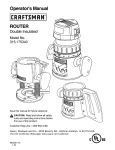
ENGLISH
User’s Guide
EZ Rider
Upright Chair
READ INSTRUCTIONS BEFORE USING
SAVE THIS BOOK FOR FUTURE REFERENCE
CONVAI D USER’S GUI DE
Customer Service Support
Toll Free: 1-888-Convai d (266-8243)
Phone: (310) 618-0111
Fax: (310) 618-8811
Emai l: custservi ce@convai d.com
Internati onal Emai l: i nternati onal@convai d.com
Websi te: www.convai d.com
Techni cal assi stance or repai r i nformati on hours are:
Monday-Fri day, 7 a.m. to 5 p.m. PST
Before Calling:
Please fill in the following information. Customer Service
will be able to help you more quickly if you have the
exact information indicated.
Serial number of chair: _______________________________
Model of chair: ______________________________________
Date purchased: _____________________________________
Dealer name: ________________________________________
Noti ce:
The i nformati on contai ned i n thi s document i s subject to change wi thout noti ce.
No part of thi s document may be photocopi ed, reproduced, transmi tted,
transcri bed, stored i n a retri eval system or translated to another language
or computer language, i n any form or by any means, electroni c, mechani cal,
magneti c, opti cal, chemi cal, manual or otherwi se wi thout the pri or wri tten
consent of Convai d, Inc.
Use only Convai d accessori es and parts on Convai d products. Convai d parts
are not i nterchangeable wi th other manufacturers’ products. Replace any
worn parts i mmedi ately.
© Copyri ght 2013 by Convai d, Inc. All ri ghts reserved.
i
CONVAI D USER’S GUI DE
Table of Contents
Setting Up
Unpacki ng the chai r . . . . . . . . . . . . . . . . . . . . . . . . . . . . . . . . . . . . . . .1
Warni ngs . . . . . . . . . . . . . . . . . . . . . . . . . . . . . . . . . . . . . . . . . . . . . . . .2
Unfoldi ng EZ Ri der . . . . . . . . . . . . . . . . . . . . . . . . . . . . . . . . . . . . . . . .3
Installi ng converti ble wheels . . . . . . . . . . . . . . . . . . . . . . . . . . . . . . . . .4
Foldi ng EZ Ri der models . . . . . . . . . . . . . . . . . . . . . . . . . . . . . . . . . . . 4
Fitting Guide
Seat back hei ght . . . . . . . . . . . . . . . . . . . . . . . . . . . . . . . . . . . . . . . . . .
Seat wi dth. . . . . . . . . . . . . . . . . . . . . . . . . . . . . . . . . . . . . . . . . . . . . . .
Seat depth . . . . . . . . . . . . . . . . . . . . . . . . . . . . . . . . . . . . . . . . . . . . . . .
Seat depth tube replacement . . . . . . . . . . . . . . . . . . . . . . . . . . . . . . . . .
Attachi ng support strap for seat depth extensi on tubes . . . . . . . . . . . .
Two-pi ece seat . . . . . . . . . . . . . . . . . . . . . . . . . . . . . . . . . . . . . . . . . . . .
Wheels
Qui ck release wheels . . . . . . . . . . . . . . . . . . . . . . . . . . . . . . . . . . . . . . . 8
Anti -shi mmy . . . . . . . . . . . . . . . . . . . . . . . . . . . . . . . . . . . . . . . . . . . . . 8
Locki ng and unlocki ng . . . . . . . . . . . . . . . . . . . . . . . . . . . . . . . . . . . . . 9
Operating Instructions
Three-poi nt posi ti oni ng belt . . . . . . . . . . . . . . . . . . . . . . . . . . . . . . . .10
H-harness wi th padded covers . . . . . . . . . . . . . . . . . . . . . . . . . . . . . .11
Depth adjustable crotch strap . . . . . . . . . . . . . . . . . . . . . . . . . . . . . . .11
Footplate hei ght adjustment . . . . . . . . . . . . . . . . . . . . . . . . . . . . . . . . 12
Angle adjustable footplates . . . . . . . . . . . . . . . . . . . . . . . . . . . . . . . . . 13
Foot posi ti oners . . . . . . . . . . . . . . . . . . . . . . . . . . . . . . . . . . . . . . . . . 14
Footplate securement strap . . . . . . . . . . . . . . . . . . . . . . . . . . . . . . . . .14
Footplate depth adjustment . . . . . . . . . . . . . . . . . . . . . . . . . . . . . . . . 14
Caster locks . . . . . . . . . . . . . . . . . . . . . . . . . . . . . . . . . . . . . . . . . . . . . 15
Calf panel . . . . . . . . . . . . . . . . . . . . . . . . . . . . . . . . . . . . . . . . . . . . . . 15
Addi ti onal Accessori es: Swi ng-away lateral support . . . . . . . . . . . .16
Full torso swi ng-away vest support . . . . . . .20
Lateral thi gh support (adductor) . . . . . . . . 20
Medi al thi gh support (abductor) . . . . . . . . 20
Padded headwi ngs . . . . . . . . . . . . . . . . . . . . . . . . . . . . . . . . . . . . . . . 21
Headrest extensi on . . . . . . . . . . . . . . . . . . . . . . . . . . . . . . . . . . . . . . . 21
Hei ght adjustable fli p-up armrests . . . . . . . . . . . . . . . . . . . . . . . . . . . 22
Occi headwi ng . . . . . . . . . . . . . . . . . . . . . . . . . . . . . . . . . . . . . . . . . . .22
5 poi nt harness . . . . . . . . . . . . . . . . . . . . . . . . . . . . . . . . . . . . . . . . . .23
Seat cushi ons . . . . . . . . . . . . . . . . . . . . . . . . . . . . . . . . . . . . . . . . . . . .25
Accessories
Upper extremi ty support surface (Tray) . . . . . . . . . . . . . . . . . . . . . . 27
Converti ble surface (Tray . . . . . . . . . . . . . . . . . . . . . . . . . . . . . . . . . . 27
Headrest cover (Canopy) . . . . . . . . . . . . . . . . . . . . . . . . . . . . . . . . . . 28
Heavy duty rei nforced upholstery . . . . . . . . . . . . . . . . . . . . . . . . . . . .29
Reducer seat i nsert . . . . . . . . . . . . . . . . . . . . . . . . . . . . . . . . . . . . . . . .29
Rear anti -ti p tubes . . . . . . . . . . . . . . . . . . . . . . . . . . . . . . . . . . . . . . . .29
Uti li ty bag . . . . . . . . . . . . . . . . . . . . . . . . . . . . . . . . . . . . . . . . . . . . . .30
Foam tray . . . . . . . . . . . . . . . . . . . . . . . . . . . . . . . . . . . . . . . . . . . . . . .30
Transit Models
Miscellaneous
5
5
6
6
7
7
Bus transport models . . . . . . . . . . . . . . . . . . . . . . . . . . . . . . . . . . . . . 31
Fabri c removal . . . . . . . . . . . . . . . . . . . . . . . . . . . . . . . . . . . . . . . . . . 32
Adjustable tensi on back . . . . . . . . . . . . . . . . . . . . . . . . . . . . . . . . . . . .32
Planar Options
Planar adjustments . . . . . . . . . . . . . . . . . . . . . . . . . . . . . . . . . . . . . . 33
Important
Information
Mai ntenance, operati ng and safety i nstructi ons . . . . . . . . . . . . . . . . 38
Warranty . . . . . . . . . . . . . . . . . . . . . . . . . . . . . . . . . . . . . . . . Back cover
ii
CONVAI D USER’S GUI DE
EZ Rider
EZ Rider Planar
Convertible
Convertible Planar
iii
SETTI NG UP
Unpacking
Unpacking the Chair
Check to see that the followi ng i tems are i ncluded wi th the chai r:
• Left and ri ght footplates
• Accessori es as ordered
• Hex wrench (5/32)
1
CONVAI D USER’S GUI DE
Warnings
Read Before Use
!
CAUTION: Keep fingers free of folding mechanism when folding the chair.
!
CAUTION: Pull wheel in opposite direction of attachment to ensure axle is
properly attached to frame when mounting convertible wheels.
!
CAUTION: To prevent injury, keep hands clear of moving structure
during folding.
!
CAUTION: Always secure user with belt first, before making any other
adjustments.
!
CAUTION: Keep fingers away from moving parts when installing/removing
Headrest cover (canopy).
!
CAUTION: Convaid belts and shoulder straps are for positioning only
and are not to be used as a vehicle restraint.
Note: Tray, storage basket, and canopy must be removed duri ng transport i n
bus or van, except when medi cally neccessary.
Note: Convai d recommends the use of all Transi t Requi red Accessori es duri ng
transportati on i n a motor vehi cle; whi ch i nclude the H-harness wi th 3-poi nt
pelvi c belt (used for posi ti oni ng), Headrest Extensi on, and Foot Posi ti oners.
2
!
CAUTION: Ensure the wheels are installed properly. You will hear a “click”
when wheel locks into place.
!
CAUTION:
•
•
•
•
•
•
For increased safety, the seat belt should be used at all times.
Do not leave user unattended.
Do not strap user too tight.
Straps should not interfere with breathing or circulation.
Always apply wheel locks before letting go of the chair.
If front edge of seat is at or forward of the point where tires
touch the floor, avoid using front of seat tubes for support
during entry or exit from chair to prevent tipping.
• Avoid using footplates for weight support during exit or entry
of the chair.
SETTI NG UP
Set-up and Adjustments
Unfolding EZ Rider Models
1. Undo locki ng bar.
2. Stand chai r on front casters. Fig. 1
3. Grasp one handle and push down on the opposi te seat
tube. Fig. 2
4. Press down fi rmly on seat tubes to ensure the chai r i s
completely unfolded. Fig. 3
5. Lock rear lock brace. Push brace downward unti l i t locks
i nto place. Fig. 4A & 4B
6. Engage wheel locks. For Converti bles, i nstall large rear
wheels.
• For Convertible Large Wheel i nstallati on, see page 4.
• For Planar Seat and Back i nstallati on & i nstructi on,
see page 33.
Fig.3
Fig.2
Fig.1
!
Caution:
Keep
fingers
free of
folding
mechanism.
Fig.4A
Fig.4B
3
CONVAI D USER’S GUI DE
Installing Convertible Large Wheels
1. To i nstall wheels, li ft frame at rear legs.
2. Depress button on qui ck release axle.
3. Push wheel axle i nto the axle housi ng on
frame unti l a cli ck i s heard. Fig. 5
!
Caution: Pull wheel in
opposite direction of
attachment to ensure
axle is properly
attached to frame.
Fig.5
Folding
1. Fli p footplates to si de.
2. Fli p back armrests. (When on chai r)
3. Unlock brace by pulli ng upward on brace. Fig. 6
4. Grasp one handle and pull up on center of seat. Fig. 7
5. Lay chai r flat wi th seat faci ng upward. Push on seat tubes to
complete fold.
Convertible Note:
The large rear wheels
on the Convertible
must be removed
before folding.
Fig.7
Fig.6
Locking
!
Caution: To prevent
injury, keep hands clear
of moving structure
during folding.
To keep chai r folded, rotate
locki ng bar over front legs.
Fig. 8
Carrying
Fig.8
When carryi ng or li fti ng chai r, grasp the foam
handle near locki ng bar.
4
FI TTI NG GUI DE
Fitting Guide
Convai d’s li ghtwei ght, foldi ng chai rs are desi gned to be more than just a conveni ent
chai r. Order the correct si ze chai r by fi rst determi ni ng the user’s hei ght, wei ght and
seati ng measurements. Properly-fi tted, Convai d chai rs wi ll provi de years of comfortable use. As your chi ld grows, refer back to thi s Fi tti ng Gui de to adjust the di mensi ons
of the chai r.
Correct seati ng and posi ti oni ng encourages good posture, whi ch i n turn ai ds ci rculati on, breathi ng and di gesti on. Please take the ti me to properly adjust the chai r to fi t the
user. If the user i s not correctly posi ti oned, check the accessori es secti on of thi s manual
to see i f one or more of our accessori es would help to faci li tate posture or consult a
physi cal therapi st. Improper seati ng can cause problems. Please consult a physi cal therapi st or doctor for addi ti onal gui dance.
Seat back hei ght
Seat Back Height
Seat back hei ght vari es accordi ng to chai r type and seatwi dth.
Headrest extensi ons are avai lable when extra hei ght i s needed
to support the head.
To determi ne the seat back hei ght, measure from the seat to the
top of the shoulder or the upper part of the head.
Fig. 9
Fig.9
Seat Width
Proper seat wi dth enables the user to si t comfortably and prevents problems from developi ng. Whi le user i s seated on a flat
surface, measure from hi p to hi p. Fig.10
The user should have enough room to prevent hi ps and thi ghs
from rubbi ng agai nst the frame. However, the chai r should not
be too wi de or the user wi ll sli de around and posture could be
affected.
The seat wi dth measurement for the EZ Ri der,i s taken from the
actual seat wi dth.
Fig.10
5
CONVAI D USER’S GUI DE
Seat Depth
Measure from the most posteri or
porti on of the buttocks to the
back of the knee. Subtract from
that measurement 1-2” to allow
adequate clearance between the
seat and the back of the knee.
Fig. 11
at
Se
To change seat depth, parti ally fold
the chai r to reli eve fabri c tensi on.
Undo the Velcro® back panel of the
two pi ece seat. Grasp end of seat
tube, depress spri ng button and
move seat tube unti l spri ng button
relocates i nto the desi red hole.
Repeat for other si de of seat. Fig. 12
pth
de
Fig.11
Fig.12
Seat Depth Tube Replacement
1. To change seat tubes or remove the seat tubes,
press grey detent pi n. To i nstall new seat tubes,
press grey detent pi n and release when desi red
setti ng i s achi eved. Repeat for opposi te si de.
Fig. 13 & 14
2. Rei nstall fabri c. Repeat for opposi te si de.
Planars EZ and Converti ble
3. Ali gn the Velcro stri ps on the bottom of the planar
cushi on wi th the Velcro on the fabri c seat and
push downwards.
4. On each si de, wrap the straps attached to the planar
seat cushi on around the chai r si de frame and buckle.
6
Fig.13
Fig.14
FI TTI NG GUI DE
Attaching Support Strap for Seat
Extension Tubes
1. Remove Seat Upholstery. Fig. A & B
2. Change and Install Seat Depth Tubes.
Press grey detent pi n and move Seat
Depth Tube to desi re setti ng. Fig. C
3. Install Support Strap. Note: Make
sure rough, shi ny si de of strap i s
faci ng out. Fig. D-G
4. Install Seat Upholstery. Fig. H
E
F
FOR TEXTILENE UPHOLSTERY:
Make sure the seat depth
tube i nserts i nto the black
web loop located on the
i nsi de corner of the
texti lene upholstery.
Fig. I-K
I
A
B
C
D
G
H
J
K
Please Note:
Do not use black web loop on the shortest adjustment of the small seat depth tubes.
Two-Piece Seat
The lower seat panel i s attached to the back panel wi th Velcro®.
It i s used to take up slack i n the seat panel after seat depth
adjustments have been made. Fig. 15, 16 & 17
Excessi ve Velcro®
overlap li fts seat
fabri c and pushes
hi ps forward, creati ng
poor posture and
reduci ng effecti ve
seat depth.
Reduced
seat
Fig. 16
depth
Wrong
Correct Velcro®
adjustment provi des
room for hi ps, and
makes greater use
of seat depth.
Fig. 15
Right
Fig. 17
7
CONVAI D USER’S GUI DE
Wheel Locks
Quick Release Wheels
TIRE REMOVAL
1.To remove, press down and hold the Rear Wheel Locki ng Pi n. Grasp wheel and pull.
2. No tools are requi red to remove ti re.
B
A
Rear Wheel Locki ng Pi n
C
TIRE INSTALLATION
!
Caution: Ensure the wheels are installed properly. You will hear a “click” when
wheel locks into place.
1. To i nstall, sli de wheel
onto rear axle and push
wi th ball of hand unti l i t
cli cks i nto place.
D
E
Anti-Shimmy
If the front wheels develop a shi mmy, use a wrench to
ti ghten the stem nut. Adjust the stem nut clockwi se unti l
the shi mmy di sappears.
Fig. F
F
8
WH EELS
Locking and Unlocking
Convai d manufactures two types of wheel locks: hand operated and foot operated.
Check to see whi ch type of wheel locks are on your chai r.
Foot Operated Wheel Locks
To lock:
Li ft upward
on wheel lock
To release
lock:
Press
downward
on wheel lock
To lock:
Pull down
on handle.
To
release
lock:
Pull up
on handle.
Convertible Model Only
Hand Wheel Locks
Convertible Brake
To i ni ti ate the break, push the lever towards the converti ble wheels and press down.
Fig. A
To release the break, pull up the lever away from the wheels. Fig. B
A
B
9
CONVAI D USER’S GUI DE
Operating Instructions
Three-Point Positioning Belt
The three-poi nt posi ti oni ng belt i s opti onal wi th every Convai d chai r (except the
Converti ble, whi ch has a 2-poi nt belt). Adjust the belt so the user stays securely i n posi ti on. The qui ck-release buckle i s attached to the crotch strap, and joi ns the crotch strap
to both belts.
To Buckle:
Sli p the metal clasps on
the belt strap i nto the si des
of the buckle. Fig. 18
To Release:
Press the grey button on
the buckle and pull out
the clasps. Fig. 18
!
10
Caution: Always secure
user with belt first,
before making any
other adjustments.
Fig.18
OPERATI NG I NSTRUCTI ONS
H-Harness with Padded Covers
H-harness shoulder straps help the user
retai n upri ght trunk posi ti on. To adjust,
i nsert the bolt at the end of the strap
through the grommet hole i n the seat back.
Grommet choi ce should be level wi th or
hi gher than the top of the shoulders.
Choose a hole that wi ll keep the user
secure wi thout the strap rubbi ng agai nst
the face or neck. Secure the strap wi th the
threaded knob. Fig. 19 & 20
Fig.19
Shoulder pads for the
H- harness are standard.
The pads come equi pped
wi th a snap buckle for
easy attachment. Fig. 21
Fig.21
Fig.20
Depth Adjustable Crotch Strap
The crotch strap can be adjusted by
threadi ng the strap through the desi red
slot. Fig. 22
Fig.22
11
CONVAI D USER’S GUI DE
Footplate Height Adjustment
Seat-to-footplate hei ght i s measured from the back of the knee to the bottom of
the heel. Feet or heels should rest comfortably on top of footplate. Fig. 23
All Convai d footplates are hei ght adjustable.
Footplates swi ng away for access or foldi ng.
Fo
o
hei tpla t
gh e
t
Fig.23
Pull on ri ng to remove metal pi n holdi ng footplate
i n place. Move footplate up or down, reali gn holes
and replace pi n through holes i n tube. Fig.24
Fig.24
Additional Footplate Height Adjustment
In the event that the footplate hei ght adjustment descri bed above i s i nadequate, addi ti onal
adjustments can be made.
1. Pull out metal pi n and remove the footplate extensi on tube from the frame. Fig. 25
2. Press the detent button, then pull the foot plate assembly apart. Fig. 26
3. Insert the footplate i nto the opposi te end of the footplate extensi on and re-assemble. Fig. 27
Fig.25
12
Fig.26
Fig.27
OPERATI NG I NSTRUCTI ONS
For addi ti onal range:
4. Usi ng a hex wrench (i ncluded), remove both bolts from the housi ng bracket on the
frame. Fli p the bracket upsi de down and replace bolts. Fig. 28 & 29
5. Return the footplate extensi on tube to the housi ng bracket and secure wi th metal
pi n. Fig. 30
Fig.28
Fig.29
Fig.30
Angle Adjustable Footplates
Angle adjustable footplates can be moved fore and aft, si deways, and rotated verti cally
and hori zontally. To adjust the angle, loosen the bolts on the footplate and move to
desi red posi ti on. Reti ghten the bolts. Fig. 31 - Fig. 35
Fig.32
Fig.33
Fig.34
Fig.35
Fig.31
13
CONVAI D USER’S GUI DE
Foot Positioners
Foot Posi ti oners may be cri ss-crossed over the foot to secure the whole foot Fig. 36 or
can be converted i nto si mple ankle straps. To attach foot posi ti oner, thread strap
through footplate as shown i n Fig. 37 & 38, then bolt strap to undersi de of footplate.
Foot Positioner Fig.36
Fig.37
Fig.38
Footplate Securement Strap
The securement strap holds i ndi vi dual footplates
together to prevent them from fli ppi ng up and down.
To secure the footplates, buckle the left and ri ght strap
together. Fig. 39
Fig.39
Footplate Depth Adjustment
All EZ Ri der chai rs offer adjustable
footplate depth.
Use the hex wrench to loosen the two
bolts located on the top of the footplate.
Sli de footplate forward or rearward to
desi red depth. Reti ghten bolts. Fig. 40
Fig.40
14
OPERATI NG I NSTRUCTI ONS
Caster Locks
Caster locks hold the swi vel wheels i n a forward
faci ng posi ti on to prevent the wheels from turni ng
si de to si de. (For 2’’ wi de ti res only)
Fig. 41
Fig.41
Calf Panel
Calf Panel provi des support to the lower legs to gi ve
addi ti onal comfort, support and pressure reli ef.
Fig. 42
Fig.42
15
CONVAI D USER’S GUI DE
Additional Accessories
Convai d offers a wi de vari ety of accessori es to help properly posi ti on the user.
Note: Convaid’s chairs provide a semi-contour fit around the body.
The user must be fitted correctly into the chair to achieve
optimal posture and comfort.
Swing-Away Lateral Support with Scoliosis Strap
Single Flap
Adjustable trunk support stabi li zes the trunk and mai ntai ns mi dli ne posi ti oni ng. It can be pulled to one si de for scoli osi s correcti on i f used wi th scoli osi s strap. Scoli osi s strap comes standard
wi th all trunk supports. Fig. 43
Fig.43
Fig.44
The trunk support i s attached to the chai r wi th straps that wrap
behi nd the seat back and connect wi th Velcro®. Fig. 44
Support i s achi eved by pulli ng each tri angular flap toward the
appropri ate si de, then securi ng i t by wrappi ng the strap around
the frame and attachi ng wi th Velcro®. The two flaps can also be
wrapped around the chi ld’s torso and joi ned i n the mi ddle.
Double Flap
One set of tri angular flaps
locates the mi dli ne posi ti oni ng. The second set of
flaps wrap around the
trunk for stabi li zati on.
The scoli osi s strap can be
used to pull the torso to
ei ther si de. Fig. 45
Fig.45
16
OPERATI NG I NSTRUCTI ONS
Attaching Lateral Trunk Support Single Flap
1. Attach the Lateral Trunk Support to the chai r by wrappi ng the two rear straps
around the back of the chai r and securi ng wi th Velcro®.
2. Attach the si ngle flap, by wrappi ng the strap on the left flap around the si de tubi ng
of the frame, and securi ng wi th Velcro® (repeat steps on opposi te si de)
3. Thread the scoli osi s strap through the plasti c loop on the left flap, back through the
plasti c loop on the opposi te end of the strap, and pull ti ght.
4. Bri ng the scoli osi s strap across the chest, thread i t through the plasti c loop on
opposi te flap, and fasten wi th Velcro®.
Note: The Lateral Trunk Support - Single Flap can be used to support
either the left or right side of the trunk.
• To support the ri ght si de of the trunk, attach the support to the chai r wi th the
double-si ded Velcro® strap on the left si de. Detach the strap on the ri ght flap from the
tubi ng, and ti ghten scoli osi s strap unti l desi red trunk posi ti oni ng i s obtai ned.
• To support the left si de of the trunk, attach the support to the chai r wi th the
double-si ded Velcro® strap on the ri ght si de. Detach the strap on the left flap from
the tubi ng, and ti ghten scoli osi s strap unti l desi red trunk posi ti oni ng i s obtai ned.
A
C
B
D
E
17
CONVAI D USER’S GUI DE
G
F
H
I
J
Attaching Lateral Trunk Support Double Flap
The Double Flap Lateral Trunk Support bri ngs the trunk to mi dli ne posi ti on.
• The Inner flaps mobi li ze the trunk.
• The Outer flaps centrali ze the trunk and keep the arms i n the front of the chai r.
• The Scoli strap ali gns the spi ne.
1. Attach the Lateral Trunk Support to the chai r by wrappi ng the two rear straps
around the back of the chai r and securi ng wi th Velcro®.
2 .To attach the double flap, wrap the strap on the left-hand outer flap around the si de
tubi ng of the frame and secure wi th Velcro®.
3. Thread the strap on the left-hand i nner flap i nto the plasti c loop on the outer flap
worki ng from front to back.
4. Adjust and secure strap. (Repeat steps 3 and 4 on ri ght-hand flap.)
5. Bri ng the long scoli osi s strap through the plasti c loop on the i nner flap on the
ri ght-hand si de and across the chest.
6. Thread the strap through the plasti c loop on the i nner flap on the left-hand si de.
7. Fasten the strap wi th Velcro®.
8. If addi ti onal ti ghtness i s desi red, pull the scoli osi s strap further and Velcro® i t
beyond the i nner flap.
Note: The Lateral Trunk Support - Double Flap can be used to support
either the left or right side of the trunk.
18
OPERATI NG I NSTRUCTI ONS
• To support the ri ght si de of the trunk, attach the Support to the chai r wi th the
double-si ded Velcro® strap on the ri ght.
• To support the left si de of the trunk, attach the Support to the chai r wi th the
double-si ded Velcro® strap on the left.
A
B
C
D
E
F
G
H
I
19
CONVAI D USER’S GUI DE
Full Torso Swing-Away Support Vest
An adjustable support vest keeps
the user i n place comfortably and
securely. It helps to mai ntai n mi dli ne seati ng posi ti on and prevents
forward slumpi ng. The vest i s
attached to the chai r wi th straps
that wrap around the seat back
and connect wi th Velcro®, and
shoulder straps that screw i nto the
seat back. Adjust the si de straps
for proper fi t. Fig. 46
Lateral Thigh Support (Adductor)
Fig.46
Pulls thi ghs together, i mprovi ng hi p
ali gnment and stabi li zi ng seati ng
posi ti on. The degree of adducti on can
be vari ed and can favor one si de. Fold
the adductor flaps over the thi ghs,
wrap the straps under and around
the armrest tube and attach wi th
buckle. Fig. 47
The adductor i s attached wi th
screws at the end of the seat tubes.
Fig.47
Medial Thigh Support (Abductor)
Separates the thi ghs to i mprove hi p
ali gnment and stabi li ze si tti ng
posture. Degree of abducti on can be
vari ed and can favor one si de. The
abductor flaps wrap over the user’s
thi ghs from the i nsi de to the outsi de.
The straps buckle around the seat
tube or the armrest. They can also be
wrapped around the armrest tube
twi ce for hi gh tone chi ldren. Fig. 48
The abductor i s attached wi th
screws at the end of the seat tubes.
20
Fig.48
OPERATI NG I NSTRUCTI ONS
Padded Headwings
Adjustable padded headwi ngs provi de soft foam support for mi dli ne posi ti oni ng.
Fig. 49 The padded headwi ngs can be attached at any hei ght by wrappi ng the Velcro®
straps around the frame and attachi ng at the back of the chai r. Secure headwi ngs by
tyi ng laces through the grommet holes i n the back of the seat fabri c or headrest
extensi on. Fig. 50
Fig.49
Fig.50
Headrest Extension
The headrest extensi on fi ts easi ly i nto the sockets on the seat back. Fold chai r sli ghtly.
Move rubber grommets on the mounti ng posts to adjust the hei ght of the seat back
extensi on. Fig. 51 & 52
Cordura Headrest Extension
Note:
To reduce the
possibility of injury,
the headrest extension
must be used with
transit models.
Fig. 51A
Fig. 51B
Textilene Headrest Extension
Fig. 52A
Fig. 52B
21
CONVAI D USER’S GUI DE
Height Adjustable Flip-Up Armrests
The hei ght adjustable fli p-up armrests provi de added support and posi ti oni ng. The
armrests “fli p-up” out of the way for easy access i nto the chai r, and adjust i n hei ght
for added comfort. Fig. 53
To attach or adjust the hei ght of the armrests, remove the two screws from each bracket, adjust the bracket to the desi red hei ght, and rei nsert the screws. Fig. 54
Fig. 53
Fig. 54
Occi Headwing
Occi Headwi ng supports and posi ti ons the head at the occi pi tal area. Thi s
headrest provi des added comfort, allows si de to si de head movement wi thout
obstructi on, and does not block the i ndi vi dual’s ears and li ne of vi si on.
The Occi headwi ng can be attached at any hei ght. Secure headwi ng by tyi ng
laces through the grommet holes at the back of the seat fabri c or headrest
extensi on.
22
OPERATI NG I NSTRUCTI ONS
5-Point Harness
ADJUSTING THE STRAPS
1. Release the Rear Lock Brace by li fti ng up on the center of brace A.
2. Press i n the si lver snap button on the Rear Lock Brace B and C then pull the
lock brace off of the housi ng D.
3. Pull shoulder strap through the upholstery, reposi ti on to the desi red hei ght,
and rei nsert i t back through the seat upholstery E. Sli de the shoulder
harness loop on to the Rear Lock Brace F.
Note: The shoulder straps should be positioned in slots that are slightly
above the shoulders of the child, and as the child grows, they should be
moved to maintain a height above the shoulder level.
A
B
C
D
E
F
23
CONVAI D USER’S GUI DE
4.Rei nsert the Lock Brace onto the housi ng G by pushi ng i t wi th the palm of your hand H.
Lock the Rear Lock Brace by pressi ng down on the Rear Lock Brace I.
G
H
I
ADJUSTING THE PELVIC BELT STRAP
To Tighten:
Ti ghten the pelvi c belt straps by pulli ng on
the loop located at the end of the strap A.
To Loosen:
Loosen the pelvi c belt strap by pushi ng the
gray button on the Strap Adjustment Lock
and pulli ng on the end of the strap closest
to the buckle B.
B
A
ADJUSTING THE CROTCH STRAP
To Tighten:
Ti ghten the Crotch Strap by pulli ng on the
loop located at the end of the strap A.
To Loosen :
Loosen the Crotch Strap by pushi ng the
gray button on the Strap Adjustment Lock
and pulli ng B.
24
A
B
OPERATI NG I NSTRUCTI ONS
Seat Cushions
Support: General Use Cushion
Flat foam wi th wooden i nsert Fig. 55
• Promotes stabi li ty and posture control and
provi des comfort for the user.
• Waterfall front eli mi nates pressure
poi nts at the back of the knees.
Fig. 55
Position: Medial Thigh Support and Anti-Thrust Cushion
Contoured foam wi th wooden i nsert Fig. 56
• Medi al thi gh support helps posi ti on the legs out
of adducti on and i nto better ali gnment, whi ch
can provi de for i mproved wei ght-beari ng
balance and stabi li ty.
• When used wi th a lap belt, the 1” anti -thrust
shelf i n front of the i schi als helps eli mi nate
sli di ng or thrusti ng forward of the pelvi s. Thi s
provi des i mproved stabi li ty and reduces
sacral si tti ng.
Fig. 56
Align: Lateral Pelvis and Lateral Thigh Support Cushion
Contoured foam wi th wooden i nsert Fig. 57
• Contoured edges provi de lateral, pelvi c and
thi gh posi ti oni ng to reduce lateral movement of
the pelvi s and i mprove lower extremi ty
stabi li ty.
• Increased surface contact for better
wei ght di stri buti on.
Fig. 57
25
CONVAI D USER’S GUI DE
Fitting
The fi tti ng of the cushi on should be done by a cli ni ci an. When fi tted correctly, the
cushi on wi ll help provi de stable support and promote good posture. Consult your
cli ni ci an for questi ons regardi ng i ndi vi dual needs.
Select the cushi on si ze to match the seat wi dth and depth of the chai r. Measure
the di stance between the back of the buttocks and the back of the knees. Subtract
1-2” to allow for adequate clearance between the seat and the back of the knees.
1. Apply wheel locks. Never leave occupi ed chai r unattended.
2. Wi th the materi al i denti fi cati on tag towards the rear of the chai r,
place the cushi on onto the seat upholstery. Li ne up the Velcro® straps
to secure the cushi on i n place. Front end of cushi on should li ne up
wi th the front edge of the seat upholstery. Posi ti on the hi ps of the
occupant to the back of the seat. The i schi als (seat bones) should be
centered on the seat well of the cushi on. Use posi ti oni ng belt to buckle
occupant i nto the chai r.
3. Adjust the wheelchai r footrest hei ght so that the user’s legs rest
fi rmly but comfortably on the cushi on. Proper footrest adjustment wi ll
enhance si tti ng comfort and help lower peak si tti ng pressures. If
appli cable, re-adjust armrest hei ght and lateral trunk supports.
Caution
The hei ght and wei ght of the occupant, i n conjuncti on wi th a seat cushi on,
may affect the center of gravi ty and cause the wheelchai r to become unstable,
potenti ally resulti ng i n i njury. Pri or to use, assess the stabi li ty of the wheelchai r by si tti ng i n i t wi th the cushi on attached.
Ensure the cushi on’s Velcro® i s i n good condi ti on and i s ali gned properly
wi th the Velcro on the wheelchai r seat. Make sure the cushi on i s fi rmly
attached. An i mproperly attached cushi on may cause sli di ng, potenti ally
resulti ng i n i njury.
Changes i n the user’s condi ti on or growth, wei ght or changes i n wheelchai r
equi pment or accessori es may requi re reassessment by a cli ni ci an to ensure
proper cushi on fi t and sui tabi li ty. Ski n should be constantly checked by the
user’s caregi ver for any si gns of reddened areas or ski n sensi ti vi ty. These
areas should be brought to the attenti on of your cli ni ci an. The cli ni ci an
should also assi st you wi th assessi ng the cushi on for any possi ble areas that
have bottomed out.
26
ACCESSORI ES
Accessories
Upper Extremity Support Surface (Tray)
The trays are great for feedi ng and
for trunk stabi li zati on. They feature a
safety li p and are easy to clean.
1. Depress spri ng button on
undersi de of armrest unti l tray
mount tube pops out.
Fig. 58
Fig. 59A
Fig. 59B
Fig. 60A
2. Grasp tray mount and extend unti l
locked i nto posi ti on. Fig. 58
3. Whi le holdi ng the tray wi th both
hands, squeeze black handles and
sli de onto ends of tray mount.
Fig. 59 & 60
4. When returni ng tray mount tube
i nsi de, mai ntai n ali gnment of
i ndent button i n order to secure
i ndent button i nto correct hole.
Fig. 60B
Convertible Model Only
1. Attach one si de of the tray by hooki ng the black metal hook around the armrest tube.
Fig. A
2. Grasp the hook bar on the opposi te si de of the tray, pull out and attach the hook
around the armrest tube. Fig. B
3. The tray should rest securely on armrest tubes.
Fig. C & D
A
B
C
D
27
CONVAI D USER’S GUI DE
Headrest Cover (Canopy)
ATTACHING CANOPY
1. Remove Canopy from box. (A)
2. Ali gn plasti c Canopy Retai ni ng Cli ps wi th upper
tubi ng on back of the chai r. (B) Push on cli ps wi th
the ball of your hand unti l they snap i nto place. (C)
!
Caution: Keep fingers away from moving parts.
A
3. To open, grasp top of Canopy and
push forward and rotate downward. (D-F)
4. To close the Rear Flap of Canopy, attach the Velcro
strap to Velcro recei vi ng patch on the edge of the
Canopy Hood. (G)
5. To fold, repeat above steps i n reverse order. (H)
B
28
C
D
E
F
G
H
ACCESSORI ES
Heavy-Duty Reinforced Upholstery
Heavy-duty, rei nforced, padded seat and seat back come
wi th pockets whi ch have removable plasti c sti ffeners. Use
when extra fi rmness i s requi red. Sti ffeners easi ly li ft out
of pockets for custom-formi ng wi th a heat gun.
Fig. 61
Fig.61
Reducer Seat Insert
The Reducer Seat Insert provi des proper posi ti oni ng i n an
oversi zed wheelchai r. Thi s cushi on easi ly sli ps i nto the seat
of the chai r to reduce the seat wi dth 2” and the seat depth 1”.
The ri bbed surface provi des comfort and promotes ai rflow.
Fig. 62
Fig.62
Rear Anti-Tip Tubes
1. To i nstall the anti -ti p tube, ali gn the tube wi th the end of the square frame
tubi ng located next to the rear wheel. (A)
2. Posi ti on the anti -ti p tube onto the square frame tubi ng (B), and push unti l the
“release button” pops through the hole located on the anti -ti p tube. (C)
3. Repeat steps 1 & 2 for opposi te si de.
4. To remove the Anti -Ti p Tubes, perform above steps i n reverse order.
B
A
C
See di agram below for how to confi gure Anti -Ti p Tube for your speci fi c si ze
EZ 12 & 14
EZ 16 & 18
29
CONVAI D USER’S GUI DE
Utility Bag
The Uti li ty Bag attaches to the back of
the chai r, but can be removed and
converted to a tote bag. Fig. 63 & 64
Caution: Do not
overload bag.
To attach:
1. Hook clasps onto straps.
Fig.63
Fig.64
Foam Tray
1. The Tray Armrest Securement Straps are located at the bottomof the tray.
Fig. 65
2. Wrap the Armrest Securement Straps around the armrest and buckle.
Fig. 66
Note: you may have to wrap the strap around the armrest several ti mes.
3. The Seat Securement Straps are located on each the si de of the tray near the
zi ppers.Wrap the Seat Securement Straps around the back of the chai r and buckle.
Fig. 67
Fig.65
30
Fig.66
Fig.67
TRANSI T MODELS
Transit Models
The wheelchai r transport model has been crash tested and performed
sati sfactori ly at 30 mph/20 g decelerati on. Convai d conforms to
RESNA WC19 standards. Dummy wei ghts are:
All EZ Riders
Model EZ12T........66lbs
Model EZ14T........100lbs
Model EZ16T........170lbs
Model EZ18T........170lbs
!
Caution:
Convaid belts and
shoulder straps are
for positioning only
and are not to be used
as a vehicle restraint.
/
/
/
/
30kg
45.5kg
77kg
77kg
To reduce possi bi li ty of i njury, the headrest
extensi on must always be used wi th the chai r.
The followi ng i nstructi ons should be followed to
mi ni mi ze i mpact i n case of a crash:
1. Chai r must be forward faci ng wi th
tray and storage basket removed.
2. Use only a tested, proven and compati ble
4-poi nt wheelchai r ti e-down system (WTOT),
and a 2- or 3-poi nt occupant restrai nt system
i n accordance wi th SAE J2249.
3. The wheelchai r ti e-downs must be securely
attached to the four red anchor poi nts on
the chai r. See arrows i n above photo for
anchor poi nts.
4. The occupant restrai nts must i nclude a lap
and shoulder belt, secured di rectly to the
EZ Ri der frame and si de or roof of the vehi cle.
Note: Do not over tighten this may
cause damage to the frame.
5. All floor ti e-down straps must be drawn ti ght i n the front and the back to
eli mi nate any forward/aft movement of the chai r.
6. Wheelchai r restrai nt manufacturers’ i nstructi ons must be followed preci sely to
ensure i ntended performance.
Note: Tray, storage basket, canopy and oxygen tank bag must be removed duri ng
transport i n bus or van, except when medi cally neccessary.
Note: Convai d strongly recommends the use of all Transi t Requi red Accessori es
duri ng transportati on i n a motor vehi cle; whi ch i nclude the H-harness wi th 3-poi nt
pelvi c belt (used for posi ti oni ng), Headrest Extensi on, and Foot Posi ti oners.
Q’Strai nt, Sure-Lok, Unwi n and Ortho Safe speci ali ze i n crash-tested ti e-down systems and are i n no way associ ated wi th Convai d.
Ortho Safe Systems, Inc.
Unwin Safety Systems
Q’ Straint America
Sure-Lok
Tel: 1-609-587-9444
Tel: +44-(0)1935-827744
Tel: 1-800-987-9987
Tel: 1-866-787-3565
Fax: 1-609-587-6780
Fax: +44-(0)1935-827760
Fax: 1-954-986-9987
Fax: 1-610-814-0644
PO Box 8865
Unwi n House, The Horseshoe, Coat Road
5553 Ravenswood Road #110
2501 Baglyos Ci rcle
Trenton, NJ 08650, USA
Martock, Sommerset, TA12 6EY, UK
Ft. Lauderdale, FL 33312, USA
Bethlehem, NJ 18020, USA
31
CONVAI D USER’S GUI DE
Miscellaneous
Fabric Removal
Parti ally fold the chai r to reli eve fabri c tensi on (see fold i nstructi ons on page 4).
The lower seat panel i s attached to the back panel wi th Velcro®. Remove the seat
bottom. Press grey detent pi n at the end of the seat extensi on, and take off upholstery. Fig. 68 & 69
To remove the top porti on of the seat, remove the Velcro® straps that attach the
seat upholstery to the frame, and take off upholstery. Li ft fabri c off seat tubes and
away from upper handles. The seat-rei nforci ng strap should remai n on frame.
Fig. 69 & 70
Fig.68
Fig.69
Fig.70
Adjustable Tension Back
1. To adjust the Tensi on Back, unfasten the Velcro Straps and pull to desi red
fi rmness. Fig. A
2. After adjustments are made, re-fasten Velcro straps. Repeat steps 1 and 2 on
each set of straps. Fig. B & C
A
32
B
C
PLANAR OPTI ON
Planar Options
Attaching Planar Seat
To attach the soli d planar seat:
1. Velcro® the soli d seat onto the fabri c seat. Fig. 71
2. On each si de, wrap the straps attached to the seat
around the chai r frame and buckle. Fig. 72
Fig.72
EZ Rider Planar
Fig.71
Attaching Planar Back
Attach the planar back by
wrappi ng the straps around
chai r frame and attachi ng
wi th the Velcro®.
Fig. 73
Fig.73
33
CONVAI D USER’S GUI DE
Planar Back Adjustments
Adjust seat back hei ght by removi ng/addi ng secti ons.
To remove a secti on:
1. Usi ng an Allen wrench, remove the bottom set of screws on the lower mounti ng plate
on the back of the uni t. Fig. A
2. Separate the upper secti on from the base. Fig. B
3. Remove bottom set of screws from upper mounti ng plate. Fig. C
4. Remove mi ddle secti on. Fig. D
5. Attach upper secti on to base secti on by re-i nserti ng the screws as shown. Fig. E
To add a secti on: Perform steps 1 – 5 i n reverse order.
C
A
B
D
E
34
PLANAR OPTI ON
Planar Positioning Options
H-Harness with Padded Covers
H-harness shoulder straps help the user retai n upri ght trunk posi ti on. To reposi ti on
the H-harness:
Remove the Planar Back from chai r. Remove the H-harness by unscrewi ng i t from
the back. Fig. 74 Reposi ti on the H-harness straps by placi ng the screw through the
grommet hole on each strap and screwi ng i t i nto the appropri ate hole on the planar
back. Bri ng the straps to the front of the planar back, threadi ng between secti ons i f
necessary. Re-attach the planar back to the chai r. Make any necessary adjustments to
the hei ght of the H-harness straps by movi ng the plasti c sli der up or down. After all
adjustments are made, attach the H-harness to the three poi nt posi ti oni ng belt wi th
the spri ng snaphook at the end of the H-harness. Fig. 75
Fig.74
Note: Velour-covered
shoulder pads for the
H-harness are standard.
Fig.75
35
CONVAI D USER’S GUI DE
Adjustable Firm Lateral Thoracic Supports
Fi rm laterals provi de soli d support for posi ti oni ng the
trunk. The lateral supports can be set i n 3 posi ti ons:
1. Outermost Position: Laterals are i nstalled at the furthest
poi nt outwards – as shi pped. Fig. A
2. Midline Position: Use Allen wrench to unscrew the foam
pad. Fig. B Unscrew the lateral brace and rotate i t
so that the short si de of the brace i s flat on the seat
back and the long si de i s perpendi cular to the seat as
shown. Fig. C
Screw the lateral brace back onto the planar back.
Fig. D Reattach the foam pad to the brace.
B
C
A
D
3. Innermost Position: Usi ng Allen wrench, unscrew the foam pad. Fig. E
Unscrew the lateral brace and rotate i t so that the long si de of the brace i s flat on the
seat back and the short si de i s perpendi cular to the seat as shown. Re-attach the
lateral brace Fig. F Screw the lateral foam pad back on the i nsi de of the brace,
leavi ng i t sli ghtly loose to allow for adjustments, and then ti ghten. Fig. G
E
36
F
G
PLANAR OPTI ON
Full Torso Swing-Away Support Vest
An adjustable support vest keeps the user i n place comfortable and securely. It helps
mai ntai n mi dli ne-seati ng posi ti on and prevents forward slumpi ng. The vest i s
attached to the chai r wi th straps that wrap around the seat back and connect wi th
Velcro®, and shoulder straps that screw i nto the soli d seat back. Adjust si de straps
for proper fi t. Fig. 76, 77 & 78
Fig.76
Fig.78
Fig.77
Contoured Firm Headrest (Headwings)
Adjust the headrest hei ght by sli ghtly
looseni ng the knobs on the seat back, and
rai si ng or loweri ng the headrest. It can also
be pi voted by changi ng the hori zontal
ali gnment of the knobs. Fig. 79
Note: A firm Backrest Extension is
recommended when using the
Headwings on the EZ Rider and
Convertible.
Note: All other positioning
options and accessories are utilized on the planar seating system the same way as on the standard EZ Rider. See front of User
Guide for detailed information.
Fig.79
37
CONVAI D USER’S GUI DE
Important Information
Maintenance, Operating & Safety Instructions
• READ ALL INSTRUCTIONS BEFORE USING THE PRODUCT
• ALWAYS FOLLOW THESE SAFETY INSTRUCTIONS
• SAVE SAFETY INSTRUCTIONS FOR FUTURE REFERENCE
CAUTION: • For increased safety, the seat belt should be used at all times.
• Do not leave user unattended.
• Do not strap user too tight.
!
• Straps should not interfere with breathing or circulation
• Always apply wheel locks before letting go of the chair.
• If front edge of seat is at or forward of the point where tires
touch the floor, avoid using front of seat tubes for support
during entry or exit from chair to prevent tipping.
• Avoid using footplates for weight support during exit or entry
of the chair.
1. Waste Disposal
The shi ppi ng carton should be kept for possi ble return to the manufacturer/servi ce
faci li ty for repai r or mai ntenance. Other paper packagi ng waste should be set asi de
for recycli ng. For di sposi ti on of replaced parts or the complete chai r, the materi als
should be separated i nto: plasti c, rubber, steel, alumi num, etc., and set asi de for
recycli ng.
2. Intended Use
Thi s product i s i ntended for use by a person wi th physi cal di sabi li ti es who i s frequently or permanently non-ambulatory. The chai r i s always under the control and
supervi si on of an attendant, and the occupant should never be left unattended.
3. Suitable Environment
The chai r i s i ntended for both i ndoor and outdoor use. If the chai r i s used i n the rai n,
the excess water should be wi ped off wi th a soft cloth. If the chai r i s splashed wi th
mud or corrosi ve substances li ke salt water or road salt, the chai r should be washed
clean wi th water, wi ped dry and a hypoallergeni c and bi odegradable lubri cant reappli ed to the movi ng parts. The chai r should never go i nto seawater, as i t wi ll corrode
areas that cannot be washed clean. When goi ng from outsi de to i nsi de, clean any
excess di rt or mud from the wheels to prevent soi li ng of i nsi de envi ronment.
38
I MPORTANT I NFORMATI ON
4. Safety Instructions
• Follow foldi ng/unfoldi ng i nstructi ons.
• Never leave occupi ed chai r unattended.
• Do not attempt to take occupi ed chai r up or down stai rs, escalators,
steep i ncli nes, or i cy or sli ppery surfaces.
• To avoi d ti ppi ng, do not overload the chai r, or hang heavy i tems on the handles that
mi ght cause ti ppi ng.
• Be aware of newly created sharp edges.
• Frequently i nspect the adjustments on the frame and the posi ti oni ng accessori es.
• Do not use chai r after occupant has outgrown i t.
• Do not i gnore mi nor malfuncti ons and mai ntai n the chai r i n good operati ng condi ti on.
Moni tor the wheel locks (brakes) regularly and adjust as needed.
• When goi ng up a curb or step, face the chai r forward and ti lt back to li ft the front
wheels over the curb. Move forward and li ft the rear wheels over the curb.
• If and whenever possible and feasible, the rider should transfer out of the chair
and into an approved vehicle seat and passenger restraint system.
However, i f a transfer i s not possi ble, use only desi gnated chai rs i n a movi ng vehi cle
whi ch contai n the Wheelchai r Ti edown and Occupant Restrai n System (WTORS)
followi ng the requi rements of SAE J2249. Follow ti e-down harness manufacturer’s
i nstructi ons carefully and refer to Convai d’s ‘Transi t Gui de’ for speci fi cs.
• When goi ng up a curb or step, face forward and
ti lt the chai r back to li ft the front wheels over the
curb. Move forward and li ft the rear wheels over
the curb.
39
CONVAI D USER’S GUI DE
• When goi ng down a curb, approach the
curb backwards. Lower the rear wheels
down the curb and conti nue backwards,
taki ng the wei ght off the front wheels so
they can be gently lowered.
• When transferri ng user to or from chai r,
apply foot wheel locks.
• Mai ntai n control of the chai r at all
ti mes whi le goi ng up/down ramp.
Avoi d steep slopes, parti cularly wi th a
heavy occupant. If i n doubt, do not
attempt a descent unless a thi rd party
i s present to help mai ntai n control of
chai r.
5. Chair Maintenance
The followi ng mai ntenance procedures should be conducted on a regular
basi s: Exami ne your Convai d product vi sually from ti me to ti me for
possi ble wear and tear. Lubri cant* should be appli ed to frame and movi ng
parts to mai ntai n easy foldi ng and adjustment.
a) Tire Air Pressure: The ai r pressure i n your ti res should be checked
WEEKLY, si nce low ai r pressure may affect brake abi li ty.
b) Axles and Moving Parts: Axles and movi ng parts should be wi ped off
WEEKLY wi th a sli ghtly moi st cloth, to remove dust, di rt and mud.
Apply some lubri cant* after each cleani ng.
c) Repair or replace loose, worn, bent, missing or damaged parts
before using the chair!
40
I MPORTANT I NFORMATI ON
MAINTENANCE CHART
Ri ms, ti res and ti re pressure
Wheel locks and hand brakes
Accessori es
Front and rear wheel axles
Cleani ng & lubri cati ng all movi ng parts
Belts, zi ppers and Velcro closures
Seat-/ back upholstery**/tautness
Armrests & foam
Frame
Contacti ng a Convai d representati ve
for servi ce or repai r***
Weekly
Every 3
months
Every 6
months
As necessary
•
•
•
•
•
•
•
•
•
•
* Use a non-toxi c, hypoallergeni c lubri cant for all movi ng parts of the frame
** Follow cleani ng i nstructi ons for appropri ate user hygi ene
*** NOTE: Repai r or replacement of non-removable, worn or broken parts must be
performed by a quali fi ed servi ce faci li ty.
6. Cleaning and disinfection
Clean all areas that come i n contact wi th user or caregi ver wi th a
di si nfectant soluti on.
To prevent the spread of germs, di si nfectant wi pes should be used on a
regular basi s. Keep frame dry and apply a non-toxi c, hypoallergeni c and
bi odegradable lubri cant to all movi ng parts. After longer storage peri ods,
and before further use, the enti re chai r needs to be servi ced, cleaned and
di si nfected. Follow the gui deli nes of each country and regi on.
Cleaning of frame:
Frame i s to be kept dry and free of di rt and should be wi ped off wi th a
non-toxi c, hypoallergeni c and bi odegradable wi pe. Lubri cant should be
appli ed to movi ng parts as needed to mai ntai n easy foldi ng and
adjustment.
All contact wi th salt water should be avoi ded. If the chai r i s used i n
salt-water envi ronments corrosi on may occur. In the event of salt-water
exposure, the frame should be wi ped off wi th a moi st towel as soon as
possi ble. Water and a soft cloth are suffi ci ent; lubri cant should be
reappli ed to all movi ng parts.
41
CONVAI D USER’S GUI DE
Cleaning of wheels and brakes:
Wheels should be cleaned of di rt or mud after each use so as to not i nterfere wi th pushi ng
the chai r. The brakes are to be kept free of di rt or mud, so as not to i nterfere wi th locki ng.
Wi pe wheels and brakes wi th a moi st cloth as needed and readjust brakes i f i ndi cated.
Cleaning of fabric cover:
Seat and back upholstery can be easi ly removed and re-attached to the chai r for washi ng.
Use standard detergent to wash fabri c. Use the gentle cycle and cold water. Hang dry
ONLY, DO NOT place i n clothes dryer as thi s wi ll damage the seat and back upholstery.
Cushi oned parts can also be removed from chai r for washi ng or to wi pe off wi th a moi st
cloth. Before re-attachi ng them to the chai r, make sure they are completely dry.
Parts that are permanently attached may be wi ped vi gorously wi th a moi st cloth. Allow
suffi ci ent ti me to dry before placi ng user i n chai r.
7. Storage
Store your chai r i n a clean, dry area and avoi d extended exposure to moi sture. After
extended storage peri ods, and before reuse, the enti re chai r needs to be servi ced, cleaned
and di si nfected.
8. Re-use
Your Convai d chai r should undergo a wi pe-down di si nfecti on before re-use. Please use a
non-toxi c, bi odegradable di si nfectant soluti on sui table for surface di si nfecti on.
Please check the followi ng components (see MAINTENANCE CHART) for operati on,
i ntactness, and replace i f necessary:
• Wheels (tread pattern), ai r pressure i f appli cable
• Frame
• Seat- and back upholstery
• Wheel lock operati on
• Beari ngs and axles: check wear and tear/ lubri cati on
• Strai ght-runni ng stabi li ty of wheels
• Attachments
9. Repairs
User: The user can replace easi ly removable parts or accessori es, e.g. footplates and
footrest assembli es, heel loops, all fabri c i tems, hand gri ps, etc. Manufacturer/Service
Facility: Repai r or replacement of permanently attached, worn or broken parts must be
performed by a quali fi ed servi ce faci li ty. Any i ndi vi dual part of the chai r can be
replaced. If the servi ce faci li ty i s close, contact the manufacturer/servi ce faci li ty for needed repai rs for deli very i n person. Alternati vely, the chai r should be packaged i n the ori gi nal or sui table shi ppi ng carton for return to the manufacturer/servi ce faci li ty. Shi p vi a
parcel post or by pri vate package deli very
servi ces.
42
I MPORTANT I NFORMATI ON
10. Tools Required
User:
• 3⁄8”, 7⁄16”, 3⁄4” or 2 adjustable wrenches wi th 3⁄4” capaci ty Phi lli ps head screwdri ver
• Hex key 5⁄32” (i ncluded)
11. Spare Parts
If you need any spare parts for your chai r, please vi si t or call a Servi ce Faci li ty. If the
part i s not under warranty, you wi ll recei ve an esti mate of the cost and, i f necessary,
shi ppi ng i nstructi ons for the return of the chai r for repai rs.
12. Functional Tests
All four wheels should make contact wi th the floor. Wi th the chai r empty, push i t
forward on a smooth level surface wi th enough momentum to travel si x feet (2 m). The
chai r should not veer to the left or ri ght more than si x i nches (15 cm). Wheels should be
free runni ng and the wheel locks (brakes) adjusted to adequately secure the chai r.
Followi ng the fold/unfold i nstructi ons, the chai r should fold/unfold smoothly wi thout
undue effort. All fasteners should be secure. Fasteners on movi ng joi nts should not be
over ti ght. Seat fabri c should not be wi de-stretched or saggi ng. Posi ti oni ng
accessori es should be correctly adjusted and secure.
13. Authorized Service Dealer
43
Limited Lifetime Warranty
Convai d warrants to the ori gi nal retai l purchaser of the Convai d product, that i f any
part thereof proves functi onally defecti ve i n materi al or workmanshi p wi thi n the
speci fi ed warranty peri od, such defecti ve part wi ll be repai red or replaced (at Convai d’s
di screti on) free of charge. Warranty servi ce may be performed by an authori zed servi ce
center or (at Convai d’s di screti on) the factory.
Warranty Period
Frame & X-Braces ...................................Li feti me of ori gi nal retai l buyer (except on Metros & C2000)
Other components....................................One year
Fabri c & webbi ng....................................One year
Planar seat & back ..................................Fi ve years for hardware, 18 months for all other components
Metro Frame & X-Braces.........................Fi ve years
Sensi form cushi on ..................................Two years
Thi s warranty does not cover normal wear and tear or damage caused by acci dent or mi suse.
To exerci se thi s li mi ted warranty, the user should fi rst obtai n a Return Authori zati on Number
from Convai d’s customer servi ce. The product must be deli vered charges pre-pai d (UPS recommended) to the factory or to an authori zed servi ce center, together wi th a copy of the ori gi nal
i nvoi ce, the Return Authori zati on Number and a wri tten descri pti on of the problem.
THIS LIMITED WARRANTY EXCLUDES ANY CLAIM FOR INCIDENTAL OR CONSEQUENTIAL
DAMAGES. ANY IMPLIED WARRANTY APPLICABLE IS LIMITED IN DURATION TO THE
DURATION OF THIS WRITTEN WARRANTY. SOME STATES DO NOT ALLOW THE EXCLUSION
OR LIMITATIONS OF INCIDENTAL OR CONSEQUENTIAL DAMAGES OR LIMITATIONS ON HOW
LONG AN IMPLIED WARRANTY LASTS. SO THE ABOVE LIMITATIONS OR EXCLUSIONS MAY
NOT APPLY TO YOU. THERE ARE NO WARRANTIES WHICH EXTEND BEYOND THE
DESCRIPTION ON THE FACE THEREOF.
Thi s warranty gi ves you speci fi c legal ri ghts and you may have other ri ghts that vary from state to
state. Warranty appli cable i n USA only, may vary i n other countri es.
FAST FACTORY SERVICE: If bei ng wi thout your chai r creates a hardshi p, you may wi sh to
take advantage of our Fast Factory Servi ce, whether under warranty or not.
WARRANTY REPAIR: Si mply send your chai r to Convai d by UPS Next Day Ai r (prepai d).
It wi ll be fi xed and shi pped out wi thi n 48 hours by UPS Next Day Ai r at our expense.
NON-WARRANTY REPAIR: The ti me to repai r and shi p back to you wi ll be extended by the
length of ti me i t takes us to reach you for approval of esti mated repai r costs.
The CE Mark Authori zed Representati ve:
B. S. Partnershi p, 41 Dan-Y-Coed Road, Cardi ff, CF23 6NB, UK
2830 Cali forni a St, Torrance, CA 90503, USA
Toll free i n the US: 1-888-CONVAID (266-8243) • Phone: (310) 618-0111 • Fax: (310) 618-2166
Emai l: custservi ce@convai d.com • Internati onal Emai l: i nternati onal@convai d.com
Websi te: www.convai d.com
UG0012-ENG-10242013 Pri nted i n U.S.A.