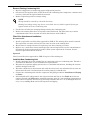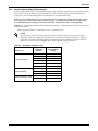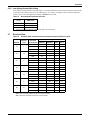
1
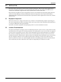
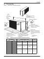
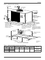
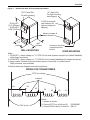
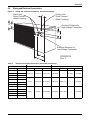
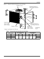
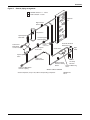
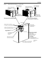
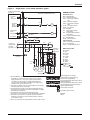
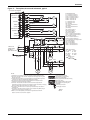
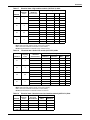
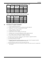
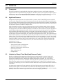
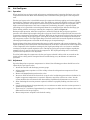
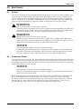
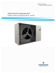
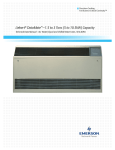
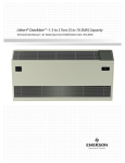
Liebert® Prop Fan Condensing Unit™
User Manual–50 & 60Hz
Figure i
Model number nomenclature
Example: PFH037A-PL7
PFH
Prop Fan Condensing
Unit with Hot-Gas
Bypass
0
37
A
Nominal Capacity
1000 BTU/Hr
0 = Standard Noise Level
Z =Quiet-Line
—
P
— = Standard Coil
C = Coated Coil
A = Air Cooled
Not all options and/or voltage combinations are available.
L
7
L = 95°F (35°C) Ambient
Liebert Lee-Temp
H = 105°F (41°C) Ambient
Liebert Lee-Temp
P = 208/230-1ph-60Hz
Y = 208/230-3ph-60Hz
A = 460-3ph-60Hz
B = 575-3ph-60Hz
S = 220-1ph-50Hz
M = 380/415-3ph-50Hz
R-407C Refrigerant
TABLE OF CONTENTS
1.0
PRODUCT DESCRIPTION . . . . . . . . . . . . . . . . . . . . . . . . . . . . . . . . . . . . . . . . . . . . . . . . . . .1
1.1
Prop Fan Condensing Units. . . . . . . . . . . . . . . . . . . . . . . . . . . . . . . . . . . . . . . . . . . . . . . . . . . . 1
1.1.1
1.1.2
1.1.3
1.2
Base System 95°F (35°C) Ambient Models . . . . . . . . . . . . . . . . . . . . . . . . . . . . . . . . . . . . . . . . . 1
105°F (41°C) Ambient Models . . . . . . . . . . . . . . . . . . . . . . . . . . . . . . . . . . . . . . . . . . . . . . . . . . . 1
Liebert Quiet-Line™ Models . . . . . . . . . . . . . . . . . . . . . . . . . . . . . . . . . . . . . . . . . . . . . . . . . . . . 1
Optional Equipment . . . . . . . . . . . . . . . . . . . . . . . . . . . . . . . . . . . . . . . . . . . . . . . . . . . . . . . . . . 1
1.2.1
1.2.2
1.2.3
Coated Coil . . . . . . . . . . . . . . . . . . . . . . . . . . . . . . . . . . . . . . . . . . . . . . . . . . . . . . . . . . . . . . . . . . 1
Refrigerant Line Sweat Adapter Kit . . . . . . . . . . . . . . . . . . . . . . . . . . . . . . . . . . . . . . . . . . . . . . 1
277V Step-Down Transformer . . . . . . . . . . . . . . . . . . . . . . . . . . . . . . . . . . . . . . . . . . . . . . . . . . . 1
2.0
INSTALLATION . . . . . . . . . . . . . . . . . . . . . . . . . . . . . . . . . . . . . . . . . . . . . . . . . . . . . . . . . .2
2.1
Equipment Inspection . . . . . . . . . . . . . . . . . . . . . . . . . . . . . . . . . . . . . . . . . . . . . . . . . . . . . . . . 2
2.2
Location Considerations. . . . . . . . . . . . . . . . . . . . . . . . . . . . . . . . . . . . . . . . . . . . . . . . . . . . . . . 2
2.3
Dimensional Data. . . . . . . . . . . . . . . . . . . . . . . . . . . . . . . . . . . . . . . . . . . . . . . . . . . . . . . . . . . . 3
2.4
Piping and Electrical Connections. . . . . . . . . . . . . . . . . . . . . . . . . . . . . . . . . . . . . . . . . . . . . . . 6
2.5
Piping Considerations . . . . . . . . . . . . . . . . . . . . . . . . . . . . . . . . . . . . . . . . . . . . . . . . . . . . . . . 14
2.5.1
2.5.2
2.5.3
2.5.4
2.5.5
2.5.6
2.6
Piping for Elevation Differences between PFH and Evaporator . . . . . . . . . . . . . . . . . . . . . . .
Pre-Charged Line Sets . . . . . . . . . . . . . . . . . . . . . . . . . . . . . . . . . . . . . . . . . . . . . . . . . . . . . . . .
Field-Fabricated Line Sets. . . . . . . . . . . . . . . . . . . . . . . . . . . . . . . . . . . . . . . . . . . . . . . . . . . . .
Installation of Piping to Units . . . . . . . . . . . . . . . . . . . . . . . . . . . . . . . . . . . . . . . . . . . . . . . . . .
R-407C PFH Installed as a Replacement Condensing Unit in an R-22 System . . . . . . . . . . .
General System Charge Requirements . . . . . . . . . . . . . . . . . . . . . . . . . . . . . . . . . . . . . . . . . . .
14
16
16
18
18
20
Electrical Connections . . . . . . . . . . . . . . . . . . . . . . . . . . . . . . . . . . . . . . . . . . . . . . . . . . . . . . . 21
2.6.1
2.6.2
Low-Voltage Control Wire Connections . . . . . . . . . . . . . . . . . . . . . . . . . . . . . . . . . . . . . . . . . . 21
Low-Voltage Control Wire Sizing . . . . . . . . . . . . . . . . . . . . . . . . . . . . . . . . . . . . . . . . . . . . . . . 22
2.7
Electrical Data . . . . . . . . . . . . . . . . . . . . . . . . . . . . . . . . . . . . . . . . . . . . . . . . . . . . . . . . . . . . . 22
2.8
Checklist for Completed Installation . . . . . . . . . . . . . . . . . . . . . . . . . . . . . . . . . . . . . . . . . . . 24
3.0
OPERATION . . . . . . . . . . . . . . . . . . . . . . . . . . . . . . . . . . . . . . . . . . . . . . . . . . . . . . . . . . .25
3.1
Compressor . . . . . . . . . . . . . . . . . . . . . . . . . . . . . . . . . . . . . . . . . . . . . . . . . . . . . . . . . . . . . . . . 25
3.2
High Head Pressure . . . . . . . . . . . . . . . . . . . . . . . . . . . . . . . . . . . . . . . . . . . . . . . . . . . . . . . . . 25
3.3
Liebert® Lee-Temp™ Flood Back Head Pressure Control . . . . . . . . . . . . . . . . . . . . . . . . . . . 25
3.4
Hot Gas Bypass . . . . . . . . . . . . . . . . . . . . . . . . . . . . . . . . . . . . . . . . . . . . . . . . . . . . . . . . . . . . 26
3.4.1
3.4.2
Operation . . . . . . . . . . . . . . . . . . . . . . . . . . . . . . . . . . . . . . . . . . . . . . . . . . . . . . . . . . . . . . . . . . 26
Adjustment . . . . . . . . . . . . . . . . . . . . . . . . . . . . . . . . . . . . . . . . . . . . . . . . . . . . . . . . . . . . . . . . . 26
4.0
MAINTENANCE . . . . . . . . . . . . . . . . . . . . . . . . . . . . . . . . . . . . . . . . . . . . . . . . . . . . . . . . . 27
4.1
General . . . . . . . . . . . . . . . . . . . . . . . . . . . . . . . . . . . . . . . . . . . . . . . . . . . . . . . . . . . . . . . . . . . 27
4.2
Compressor Failure . . . . . . . . . . . . . . . . . . . . . . . . . . . . . . . . . . . . . . . . . . . . . . . . . . . . . . . . . 27
4.2.1
4.2.2
Electrical Failure—Burnout . . . . . . . . . . . . . . . . . . . . . . . . . . . . . . . . . . . . . . . . . . . . . . . . . . . 28
Mechanical Failure. . . . . . . . . . . . . . . . . . . . . . . . . . . . . . . . . . . . . . . . . . . . . . . . . . . . . . . . . . . 28
4.3
Compressor Replacement. . . . . . . . . . . . . . . . . . . . . . . . . . . . . . . . . . . . . . . . . . . . . . . . . . . . . 28
4.4
Field Charge Verification. . . . . . . . . . . . . . . . . . . . . . . . . . . . . . . . . . . . . . . . . . . . . . . . . . . . . 29
5.0
TROUBLESHOOTING . . . . . . . . . . . . . . . . . . . . . . . . . . . . . . . . . . . . . . . . . . . . . . . . . . . . . 30
i
FIGURES
Figure i
Figure 1
Figure 2
Figure 3
Figure 4
Figure 5
Figure 6
Figure 7
Figure 8
Figure 9
Figure 10
Figure 11
Figure 12
Model number nomenclature . . . . . . . . . . . . . . . . . . . . . . . . . . . . . . . . . . . . . . . . . Inside Front Cover
Dimensions, horizontal air discharge . . . . . . . . . . . . . . . . . . . . . . . . . . . . . . . . . . . . . . . . . . . . . . . . 3
Dimensions, top air discharge . . . . . . . . . . . . . . . . . . . . . . . . . . . . . . . . . . . . . . . . . . . . . . . . . . . . . . 4
Dimensional data, 277V step-down transformer . . . . . . . . . . . . . . . . . . . . . . . . . . . . . . . . . . . . . . . 5
Piping and electrical connections, horizontal discharge . . . . . . . . . . . . . . . . . . . . . . . . . . . . . . . . . . 6
Piping and electrical connections, top air discharge . . . . . . . . . . . . . . . . . . . . . . . . . . . . . . . . . . . . . 7
General piping arrangement . . . . . . . . . . . . . . . . . . . . . . . . . . . . . . . . . . . . . . . . . . . . . . . . . . . . . . . 8
Electrical field connections, 1- to 5-ton units . . . . . . . . . . . . . . . . . . . . . . . . . . . . . . . . . . . . . . . . . . 9
Electrical field connections, 8-ton units. . . . . . . . . . . . . . . . . . . . . . . . . . . . . . . . . . . . . . . . . . . . . . 10
Single-phase, 1-3 ton model schematic, typical. . . . . . . . . . . . . . . . . . . . . . . . . . . . . . . . . . . . . . . . 11
Three-phase, 3-5 ton model schematic, typical . . . . . . . . . . . . . . . . . . . . . . . . . . . . . . . . . . . . . . . . 12
Three-phase, 8 ton model schematic, typical. . . . . . . . . . . . . . . . . . . . . . . . . . . . . . . . . . . . . . . . . . 13
Refrigerant piping diagram . . . . . . . . . . . . . . . . . . . . . . . . . . . . . . . . . . . . . . . . . . . . . . . . . . . . . . . 15
TABLES
Table 1
Table 2
Table 3
Table 4
Table 5
Table 6
Table 7
Table 8
Table 9
Table 10
Table 11
Table 12
Table 13
Table 14
Table 15
Table 16
Table 17
Table 18
Table 19
Table 20
Table 21
Table 22
Table 23
Cabinet and floor planning data, horizontal air discharge. . . . . . . . . . . . . . . . . . . . . . . . . . . . . . . . 3
Electrical and piping connections, top air discharge . . . . . . . . . . . . . . . . . . . . . . . . . . . . . . . . . . . . 4
Electrical and piping connections, horizontal air discharge. . . . . . . . . . . . . . . . . . . . . . . . . . . . . . . 6
Piping and electrical connections, top air discharge . . . . . . . . . . . . . . . . . . . . . . . . . . . . . . . . . . . . . 7
Pipe length and condenser elevation relative to evaporator . . . . . . . . . . . . . . . . . . . . . . . . . . . . . 15
Equivalent lengths for various pipe fittings, ft (m). . . . . . . . . . . . . . . . . . . . . . . . . . . . . . . . . . . . . 15
Refrigerant charge in Liebert pre-charged R-407C line sets . . . . . . . . . . . . . . . . . . . . . . . . . . . . . 16
Liebert® PFH unit charge levels and coupling size . . . . . . . . . . . . . . . . . . . . . . . . . . . . . . . . . . . . 17
Recommended line sizes, OD Cu . . . . . . . . . . . . . . . . . . . . . . . . . . . . . . . . . . . . . . . . . . . . . . . . . . . 17
Piping connection sizes and torque . . . . . . . . . . . . . . . . . . . . . . . . . . . . . . . . . . . . . . . . . . . . . . . . . 18
Line charges - refrigerant per 100 ft. (30m) of Type L copper tube . . . . . . . . . . . . . . . . . . . . . . . . 18
Evaporator Charge Levels . . . . . . . . . . . . . . . . . . . . . . . . . . . . . . . . . . . . . . . . . . . . . . . . . . . . . . . . 20
Design refrigerant pressures . . . . . . . . . . . . . . . . . . . . . . . . . . . . . . . . . . . . . . . . . . . . . . . . . . . . . . 21
Application limits . . . . . . . . . . . . . . . . . . . . . . . . . . . . . . . . . . . . . . . . . . . . . . . . . . . . . . . . . . . . . . . 21
Recommended minimum wire size. . . . . . . . . . . . . . . . . . . . . . . . . . . . . . . . . . . . . . . . . . . . . . . . . . 22
Electrical data—Standard sound and ambient models (95°F/35°C) 60Hz . . . . . . . . . . . . . . . . . . 22
Electrical data—High ambient models (105°F/41°C) 60Hz . . . . . . . . . . . . . . . . . . . . . . . . . . . . . . 23
Electrical data—Quiet-Line models (95°F/35°C) 60Hz . . . . . . . . . . . . . . . . . . . . . . . . . . . . . . . . . 23
Electrical data—Standard sound and ambient models (95°F/35°C) 50Hz . . . . . . . . . . . . . . . . . . 23
Electrical data—High ambient models (105°F/41°C) 50Hz . . . . . . . . . . . . . . . . . . . . . . . . . . . . . . 24
Electrical data—Quiet-Line models (95°F/35°C) 50Hz . . . . . . . . . . . . . . . . . . . . . . . . . . . . . . . . . . 24
Field verification charge . . . . . . . . . . . . . . . . . . . . . . . . . . . . . . . . . . . . . . . . . . . . . . . . . . . . . . . . . . 29
Troubleshooting. . . . . . . . . . . . . . . . . . . . . . . . . . . . . . . . . . . . . . . . . . . . . . . . . . . . . . . . . . . . . . . . . 30
ii
Product Description
1.0
PRODUCT DESCRIPTION
1.1
Prop Fan Condensing Units
Liebert® propeller fan condensing units are available in a range of sizes and configurations to offer
flexibility in designing a precision environmental control system. The appropriate propeller fan
condensing unit paired with a corresponding Liebert fan coil evaporator model such as Liebert
DataMate™, Liebert Mini-Mate2™ or Liebert Challenger 3000™ is an effective solution for your
environmental control application requirements.
Split system condensing units are connected to the evaporator unit by two refrigerant lines (four in
8-ton systems) and a low-voltage control cable. The condensing unit requires a separate power source
and power disconnect switch.
1.1.1
Base System 95°F (35°C) Ambient Models
The heart of the refrigeration system is a quiet, high efficiency scroll compressor with internal
vibration isolation mountings, pressure safety controls and built-in overload protection. Standard
features include crankcase heater, high-pressure switch, condenser coil, sight glass, filter drier, hot
gas bypass system with liquid quenching valve, direct drive propeller fan and motor, and Liebert
Lee-Temp™ flood-back head pressure control. These models are designed to provide catalog capacity of
the appropriate evaporator section up to 95°F (35°C) outside ambient temperature.
1.1.2
105°F (41°C) Ambient Models
These models contain similar components to the base models except the coils and fans are sized to
provide catalog capacity of the appropriate evaporator section up to 105°F (41°C) outside ambient
temperature.
1.1.3
Liebert Quiet-Line™ Models
These models contain similar components to the base models except the coils and fans are sized to
provide catalog capacity of the appropriate evaporator section up to 95°F (35°C) outside ambient
temperature with a noise level of less than 58 dBA.
1.2
Optional Equipment
1.2.1
Coated Coil
This option provides a phenolic coating for the condenser coil (extended lead time is required for this
option; consult factory).
Pre-Charged Refrigeration Line Sets
For efficient condenser/evaporator connection, factory pre-charged line sets with quick connect
fittings are available in 15-ft. and 30-ft. (4.5m and 9m) lengths. Each set includes an insulated copper
suction line and copper liquid line, both charged with R-407C refrigerant and sealed. Line sets are
only available for 1 to 3.5 Ton Units.
1.2.2
Refrigerant Line Sweat Adapter Kit
This kit includes the compatible fittings required (two for the insulated suction line and two for the
liquid line) when using field-supplied interconnecting refrigerant lines instead of the pre-charged line
sets.
1.2.3
277V Step-Down Transformer
A 37.5A, 277V step-down transformer is available for 1-to 3-Ton 60Hz condensing units needing
277/1/60 input power. Apply this transformer to a 208/230/1/60 condensing unit. The transformer is
coated with epoxy and contained in an enclosed, non-ventilated electrical box with adaptable
mounting brackets.
1
Installation
2.0
INSTALLATION
Read this entire installation section before starting installation. This section details dimensional,
electrical and piping information and specifications that affect the placement of the PFH unit in
relation the connected evaporator unit, other outside units, barriers and walls.
Be particularly mindful of service and airflow clearances and maximum equivalent piping distances
and in elevation differences between PFH and connected evaporator unit. Consult and confirm
applications with your Emerson Network Power representative when applications exceed any of these
specifications.
2.1
Equipment Inspection
When the unit arrives, inspect all items for any visible or concealed damage. Report any damage to
the carrier immediately and file a damage claim; send a copy of the claim to Emerson Network Power
or your local Emerson sales representative.
If possible, maintain equipment and packaging until it is at the installation location.
2.2
Location Considerations
To ensure an adequate air supply, locate all condensing units in a clean-air area, away from loose dirt
and debris that can clog the coil. Avoid ground-level sites with public access or areas that are exposed
to heavy snow accumulation. Locate unit to allow maximum security and maintenance accessibility.
Do not locate condensing units near steam, hot air or fume exhausts. Do locate units at least 18 in.
(457mm) from walls, obstructions or adjacent units. For multiple unit installations, space unit so that
the hot condenser exhaust air is not directed toward the condenser air inlet of an adjacent unit.
Install a solid base at least 2 in. (51mm) higher than the surrounding grade and 2 in. (51mm) larger
than condensing unit base dimensions and capable of supporting the condenser’s weight.
2
Installation
2.3
Dimensional Data
Figure 1
Dimensions, horizontal air discharge
Fan Rotation
CCW
(left side)
Removable (right) panel
for access to
refrigeration component
A
Right Air Discharge
Left Air Intake
Shaded area
indicates a minimum
clearance of 18" (457mm)
for proper air flow.
B
Shaded area
indicates a recommended
clearance of 24" (610mm)
for component access and
removal.
C
Shaded area
indicates a minimum
clearance of 18" (457mm)
for proper air flow
Table 1
Removable panel for access
to high-voltage and low-voltage
connections and refrigeration
components
DPN000130
Rev. 1
Cabinet and floor planning data, horizontal air discharge
Model Numbers
60Hz
50Hz
PFH014A-L
PFH020A-L
PFH027A-L
PFH027A-H
PFHZ27A-L
PFH037A-L
PFH042A-L
PFH037A-H
PFHZ37A-L
PFH042A-H
PFHZ42A-L
PFH067A-L
—
—
—
—
—
PFH036A-L
PFH041A-L
PFH036A-H
PFHZ36A-L
PFH041A-H
PFHZ41A-L
PFH066A-L
Net Weight
lb. (kg)
Dimensional Data, in. (mm)
A
B
C
40 (1016)
23-1/2 (597)
18 (457)
200 (91)
48 (1219)
31 (787)
18 (457)
241 (109)
53 (1343)
36-1/4 (918)
18 (457)
351 (159)
Source: DPN000130, Rev. 1
3
Installation
Figure 2
Dimensions, top air discharge
Top Air
Discharge
Guard Height
Fan Rotation
CW
Right Air Intake
Shaded area
indicates a minimum
clearance of 18" (457mm)
for proper air flow.
Left Air
Intake
2"
(51mm)
Shaded area
indicates a minimum
clearance of 18" (457mm)
for proper air flow
Removable panel for access
to high-voltage and low-voltage
connections and refrigeration
components
36-1/8"
(918mm)
53-3/16"
(1351mm)
4"
(102mm) typ.
2"
(51mm) typ.
Shaded area
indicates a recommended
clearance of 24" (610mm)
for component access and
removal.
1/2" Bolt-Down Holes
(6 places)
4-23/32"
(120mm)
25-3/32"
(637mm)
32-1/8"
(816mm)
2"
(51mm)
46-7/32"
(1174mm)
DPN000131
Rev. 0
FOOTPRINT DIMENSIONS
Table 2
2"
(51mm)
Electrical and piping connections, top air discharge
Model Numbers
60Hz
50Hz
PFH067A-H
PFH066A-H
PFHZ67A-L
PFHZ66A-L
PFH096A-L
PFH095A-L
Dimensional Data in. (mm)
A
B
C
D
53 (1343)
36-1/4 (918)
38-1/2 (978)
5-1/2 (140)
Module Net
Weight, lb. (kg)
488 (222)
570 (259)
Source: DPN000131, Rev. 0
4
Installation
Figure 3
Dimensional data, 277V step-down transformer
.31" (8mm) Dia.
For rigid mounting
and shipping
.281" (7mm) Dia.
For wall mounting
1/4-20 (2 screws &
lock washers) for
rigid mounting and
shipping
1D18214P1
10.3" (262mm)
1D18214P2
11.68" (297mm)
Remove screws &
attach bracket
5.5"
(140mm)
4.92"
(125mm)
Access to electrical
connections from
bottom
WALL MOUNTING
RIGID MOUNTING
Notes:
1. 1D18214P1 = Acme catalog no. T-1-37921 for all small systems except 3-ton Liebert DataMate
with integral condenser.
2. 1D18214P2 = Acme catalog no. T-1-37922 for 3-ton Liebert DataMate with integral condenser.
3. Epoxy coated. Suitable for indoor/outdoor service. Horizontal- or vertical-mount.
Totally enclosed, non-ventilated.
4. Both brackets are shipped loose with transformer.
WIRING FOR TRANSFORMER
277V line voltage
Jumpers
H4
H2
H3
230V to unit
H1
X4
X3
X2
X1
Notes:
1. Jumper as shown.
2. Connect 277V line to H4 and X1
3. Connect 230V load to H1 and H4
5
DPN000647
REV. 0
Installation
2.4
Piping and Electrical Connections
Figure 4
Piping and electrical connections, horizontal discharge
Liquid Line
Quick Connect
(Male Coupling)
Suction Line
Quick Connect
(Male Coupling)
A
G F
Electrical Entrance for
High-Voltage Connection
B
C
Electrical Entrance for
Low-Voltage Connection
D
DPN000132
Rev. 1
E
Table 3
Electrical and piping connections, horizontal air discharge
Model Numbers
60Hz
50Hz
PFH014A-L
—
PFH020A-L
—
PFH027A-L
—
PFH027A-H
—
PFHZ27A-L
—
PFH037A-L
PFH036A-L
PFH042A-L
PFH041A-L
PFH037A-H
PFH036A-H
PFHZ37A-L
PFHZ36A-L
PFH042A-H
PFH041A-H
PFHZ42A-L
PFHZ41A-L
PFH067A-L
PFH066A-L
Electrical Connections, in (mm)
Piping Connections, in. (mm)
A
B
C
D
E
F
G
2-1/4 (57)
5-1/4 (133)
7-3/4 (197)
8-3/4 (222)
—
5 (127)
7-1/4 (184)
2 (51)
5-3/4 (146)
8-1/2 (216)
4-3/4 (121)
6-3/4 (171)
—
8-1/2 (216)
2 (51)
6 (152)
8-1/2 (216)
4-3/4 (121)
7-3/4 (197)
—
8-1/2 (216)
Source: DPN000132, Rev. 1
6
Installation
Figure 5
Piping and electrical connections, top air discharge
* System 2 (5 Ton)
Electrical Entrance for
High-Voltage Connection
Liquid Line
Quick Connect
(Male Coupling)
Electrical Entrance for
Low-Voltage Connection
* System 1 (3 Ton)
Suction Line
Quick Connect
(Male Coupling)
* System 1 and System 2 on 8 Ton only
Table 4
DPN000133
Rev. 0
Piping and electrical connections, top air discharge
Model Numbers
60Hz
50Hz
PFH067A- H
PFH066A-H
PFHZ67A- L
PFHZ66A-L
PFH096A- L
PFH095A-L
Electrical Connections
in. (mm)
Piping Connections
in. (mm)
A
B
C
D
E
F
2
(51)
6
(152)
8-1/2
(216)
4-3/4
(121)
7-3/4
(197)
8-1/2
(216)
Source: DPN000133, Rev. 0
7
G
—
—
11-1/2 (292)
Installation
Figure 6
General piping arrangement
SINGLE CIRCUIT = 1 - 5 Tons
DUAL CIRCUIT = 8 Tons
Condenser
Coil
High Pressure
Switch
Compressor *
Liquid Injection
Valve Bulb
Suction Line
Male Quick
Connect Coupling
Hot Gas Bypass
Solenoid Valve
3 - Way Head
Pressure
Control Valve
Hot Gas Bypass
Control Valve
Automatic Pressure
Relief Valve
Sight
Glass
Check Valve
Liquid Injection
Valve
Liquid Line
Solenoid Valve
Liebert
Lee-Temp
Receiver
Receiver Heater
Pressure Limiting
Pressure Balancing
Switch
Valve
Liquid Line Male Quick
Connect Coupling
SINGLE CIRCUIT SHOWN
* Scroll compressor, except 1Ton, 60Hz is reciprocating compressor.
8
DPN000129
Rev. 3
Installation
Figure 7
Electrical field connections, 1- to 5-ton units
Single- or three-phase
electric service not provided
by Liebert
Field-supplied unit
disconnect switch
Field-supplied unit
Single- or three-phase
disconnect switch
electric service not provided
by Liebert
Field-supplied 24V
NEC Class 2 wiring
to evaporator module
Field-supplied 24V
NEC Class 2 wiring
to evaporator module
Horizontal Air Discharge Models
Top Air Discharge Models
(5 Ton High Ambient or 5 Ton Quiet-Line)
Electric service connection
to contactor or terminal block
Factory-wired
to components on
electric panel
Single- or three-phase electric
service not provided by Liebert
High-voltage electric power
supply entrance
Heat rejection connection.
Field-supplied 24V NEC
Class 2 wiring.
Wire connections from
evaporator module:
1. 24V GND
2. 24V Supply
3. High Pressure Alarm
4. Hot Gas Bypass Connection
Low-voltage electric
power supply
entrance
Earth ground connection
terminal for field wiring
Refer to tables or unit serial label
for FLA, WSA and OPD values.
9
DPN000134
Rev. 1
Installation
Figure 8
Electrical field connections, 8-ton units
Field-supplied unit
disconnect switch
Single- or three-phase
electric service not provided
by Liebert
Field-supplied 24V
NEC Class 2 wiring
to evaporator module
Electric service
connection to contactor
or terminal block
Factory-wired
to components on
electric panel
Single- or three-phase electric
service not provided by Liebert
High-voltage
electric power
supply entrance
Heat rejection connection.
Field-supplied 24V NEC
Class 2 wiring.
Wire connections from evaporator module:
1. 24V GND System 1
2. 24V Supply System 1
3. High Pressure Alarm System 1
4. Hot Gas Bypass Connection System 1
5. 24V GND System 2
6. 24V Supply System 2
7. High Pressure Alarm System 2
8. Hot Gas Bypass Connection System 2
9. 24V GND Condenser Fan
10. 24V SUPPLY Condenser Fan
Low-voltage electric
power supply
entrance
Earth ground connection
terminal for field wiring
Refer to tables or unit serial label
for FLA, WSA and OPD values.
10
DPN000135
Rev. 1
Installation
Figure 9
Single-phase, 1-3 ton model schematic, typical
Conductors Field-Supplied
(See Note 5)
Unit Alarm
Input
Connection
24V Power
Supply
From Unit
Min 40 Va
HGBP Signal
Output
Connection
3
3
2
2
BL
HP1
W
C1
BK
BR
4
1
4
HG1
BR
1
24V Ground
See Note 6
BR
BK
HP2
RHTR
R
1-Phase Line
Voltage Supply
By Others
(See Notes 1 & 3)
NOMENCLATURE
OUTDOOR CONDENSING MODULE
EVAPORATOR UNIT
L1
R
BK
HG1
BK 1C1
HGSV
BK
2C1
L2
LLSV
BK
BK
CHTR
BK
Supplied on
BK 1-Ton PFH
Models Only
R
Earth Ground
By Others
CAP3
BK
R
BK
R R
BDR
CAP1
1
CAP2
BR
R
Y
PR
2
R
BR
'FM'
FAN
MOTOR
5
CSR
C RS
COMP
25,
27
Standard Devices
BDR -- Bleed Resistor
C1 -- Condenser Contactor
CAP1 -- Compressor Capacitor
Run
CAP2 -- Fan Motor Capacitor
CAP3 -- Compressor Capacitor
Start
CHTR -- Compressor Heater
COMP -- Compressor
FM -- Fan Motor
HP1 -- High Pressure Switch
(Auto Reset)
HP2 -- Pressure Switch Receiver
(Auto Reset)
LLSV -- Liquid Line Solenoid Valve
PR -- Potential Relay
RHTR -- Receiver Heater
Optional Devices
CSR -- Compressor Start Resistor
HG1 -- Hot Gas Relay
HGSV -- Hot Gas Solenoid Valve
WIRE COLOR CODE
OR - Orange
R - Red
BR - Brown
P - Purple
GN - Green
Y - Yellow
BL - Blue
BK - Black
W - White
Insulation Color
GN / Y
Tracer Color
Optional on
Selected Units
1. All units 208/230V, 1 phase. On 208/230V units installed
in Canada only, CSA requires that L1 and L2 are non-neutral
supply conductors. L1 et L2 pour conducteurs d'alimentation
non-neutres. On other units, L2 is designated neutral. See
unit name plate and installation manual for main supply wiring
information. Use copper conductors only.
2. Use copper conductors only. See unit nameplate for main supply
wire sizing data. Wire per local codes.
3. A remote disconnect switch is to be field-supplied and mounted
within sight of the condensing unit. See unit nameplate for voltage
and amperage requirements.
4. All motors have internal line break overload protectors.
Three-phase motors protected for primary single-phasing conditions.
5. Terminals 1,2,3, and 4 are for connection of control circuit from
evaporator unit. Wiring by others to be NEC Class 2 and sized
for 1V maximum drop.
6. Wire '1' is connected to the grounded side of the 24V Class 2 circuit.
11
Factory-Supplied Line Voltage
Field-Installed Line Voltage Wiring
Optional Line Voltage Wiring
Factory-Supplied 24V NEC Class 2 Wiring
Optional 24V Wiring
Factory-Supplied 24V NEC Class 2 Wiring
Factory-Supplied Earth Grounding Wire
Pigtail Leads 24V Wiring
Terminal Strip Connection
Grounding Lug Connection
191642
Rev. 1
Installation
Figure 10 Three-phase, 3-5 ton model schematic, typical
Conductors Field-Supplied
(See Note 5)
Unit Alarm
Input
Connection
24V Power
Supply
From Unit
Min 40VA
3
3
2
2
BL
HP1
W
BK
C1
27,29,30
BR
HGBP Signal
Output
Connection
24V Ground
4
4
1
1
BR
BR
HG1
See Note 6
See Note 1
F1
F2
3-Phase Line
Voltage Supply
By Others
(See Note 3)
NOMENCLATURE
OUTDOOR CONDENSING MODULE
EVAPORATOR UNIT
L1
1C1
L2
2C1
L3
3C1
BK
TX1
R
HP2
27
See Note 7
R
BK
RHTR1
BK
RHTR2
BK
HG1
HGSV
Standard Devices
C1 -- Condenser Contactor
CAP2 -- Fan Motor Capacitor
CHTR -- Compressor Heater
COMP -- Compressor
F1 -- Transformer Fuse 1
F2 -- Transformer Fuse 2
FM -- Fan Motor
HP1 -- High Pressure Switch
(Auto Reset)
HP2 -- Pressure Switch Receiver
(Auto Reset)
LLSV -- Liquid Line Solenoid Valve
RHTR1 -- Receiver Heater No. 1
RHTR2 -- Receiver Heater No. 2
(3-,4-,and 5-ton only)
TX1 -- Transformer Line
Voltage to230V
Optional Devices
HG1 -- Hot Gas Relay
HGSV -- Hot Gas Solenoid Valve
WIRE COLOR CODE
LLSV1
BR
BR
CHTR
BK
R
BR R OR
Earth Ground
By Others
Y
CAP2
BR
'FM'
Fan
Motor
T3 T2T1
COMP
1. Transformer 'TX1' provided on units with nameplate voltages greater
than 240V.
2. Use copper conductors onl y. See unit nameplate for main supply wire
sizing data. Wire per local codes.
3. A remote disconnect switch is to be field supplied and mounted
within sight of the condensing unit. See unit nameplate for voltage
and amperage requirements.
4. All motors have internal line break overload protectors. Three-phase
motors protected for primary single-phasing conditions.
5. Terminals 1, 2, 3 and 4 are for connection of control circuit from evaporator
unit. Wiring by others to be NEC Class 2 and sized for 1 volt maximum drop.
6. Wire '1' is connected to the grounded side of the 24V Class 2 circuit.
7. Receiver heater No.2 'RHTR2' supplied on 4- and 5-ton standard models and
3/3.5-ton high ambient and Quiet-Line models.
12
OR - Orange
R - Red
BR - Brown
P - Purple
GN - Green
Y - Yellow
BL - Blue
BK - Black
W - White
Insulation Color
GN / Y
Tracer Color
Factory-Supplied Line Voltage
Field-Installed Line Voltage Wiring
Optional Line Voltage Wiring
Factory-Supplied 24V NEC Class 2 Wiring
Optional 24V Wiring
Factory-Supplied 24V NEC Class 2 Wiring
Factory-Supplied Earth Grounding Wire
Pigtail Leads 24V Wiring
Terminal Strip Connection
Grounding Lug Connection
191643
Rev. 0
Installation
Figure 11
Three-phase, 8 ton model schematic, typical
Conductors Field-Supplied
(See Note 5)
Evaporator Unit
HIGH HEAD 1
COOLING 1
24V GND
HGBP1
COMP1
HIGH HEAD 2
COOLING 2
HGBP2
COMP2
3
3
2
2
10
10
9
9
4
4
1
1
7
7
6
6
8
8
5
5
OUTDOOR CONDENSING MODULE
BL
See Note 6
HP1
W
C1 Aux.
R
C2 Aux.
See Note 8
BR
See Note 7
R
See Note 8
BR
See Note 6
BL
BK
C1
MF
HG1
HP2
W
BK
C2
See Note 7
R
BR
HG2
See Note 8
HP4
See Note 1
F1
TX1
BK
R
HP3
R
R
BK
BK
RHTR2
RHTR1
F2
3-Phase Line
Voltage Supply
By Others
(See Notes 2 and 3)
BK
BK
L1
1C1
L2
2C1
L3
3C1
BR
BR
CHTR1
Earth Ground
By Others
CHTR2
HG1
HGSV1
LLSV1
WIRE COLOR CODE
OR - Orange Y - Yellow
R - Red
BL - Blue
BR - Brown
BK - Black
P - Purple
W - White
GN - Green
Insulation Color
GN / Y
Tracer Color
BR R OR
BR
BR
BR
T3 T2 T1
COMP1
1MF 2MF
3MF
1C2
HG2
STANDARD DEVICES
C1 - Compressor Contactor 1
C2 - Compressor Contactor 2
CHTR1 - Compressor Heater 1
CHTR2 - Compressor Heater 2
COMP1 - Compressor #1
COMP2 - Compressor #2
F1 - Transformer Fuse
F2 - Transformer Fuse
FM - Fan Motor
HP1 - High Pressure Switch 1
(Auto Reset)
HP2 - High Pressure Switch 2
(Auto Reset)
HP3 - Pressure Switch 3
Receiver (Auto Reset)
HP4 - Pressure Switch 4
Receiver (Auto Reset)
LLSV1 - Liquid Line Solenoid Valve 1
LLSV2 - Liquid Line Solenoid Valve 2
MF - Fan Motor Contactor
RHTR1 - Receiver Heater No.1
RHTR2 - Receiver Heater No.2
TX1 - Transformer Line Voltage to 230V
OPTIONAL DEVICES
HG1 - Hot Gas Relay 1
HG2 - Hot Gas Relay 2
HGSV1 - Hot Gas Solenoid 1
HGSV2 - Hot Gas Solenoid 2
HGSV2
2C2
3C2
LLSV2
BR R OR
T3 T2 T1
COMP
2
FM
Fan
Motor
NOTES
1. Transformer TX1 provided on units with nameplate voltages greater than 250V.
2. Use copper conductors only. See unit nameplate for main supply wire sizing data.
Wire per local codes.
3. A remote disconnect switch is to be field-supplied and mounted within sight of the
condensing unit. See unit nameplate for voltage and amperage.
4. All motors have internal line break overload protectors. Three-phase motors
protected for primary single-phasing conditions.
5. Terminals 1 thru 8 are for connection of control circuit from evaporator unit.
(Terminals 4 and 8 are not used by some evaporator models . See Note 7). Wiring by
others to be NEC Class 2 and sized for 1V maximum drop.
6. Connection to Terminals 3 and 7 is used for high head alarm input connection in
evaporator unit.
7. Connection to Terminals 4 and 8 is required only on models with (HGBP) hot gas
bypass control signal output in evaporator unit.
8. Wires 1, 5 and 9 are separately connected to the grounded side of the 24V
Class 2 circuit. Do not connect them together.
13
WIRING LEGEND
Factory-supplied line voltage
Field-installed line voltage wiring
Optional line voltage wiring
Factory-supplied 24V NEC Class 2 wiring
Optional 24V wiring
Field-supplied 24V NEC Class 2 wiring
Field-supplied earth grounding wire
Pigtail leads
Terminal strip connection
Grounding lug connection
191647
Rev. 0
Installation
2.5
Piping Considerations
The Liebert® Mini-Mate2™, Liebert DataMate™ and the 3-ton Liebert Challenger 3000™ split system
units are designed with quick-connect fittings and are factory-charged to proper refrigerant levels.
This permits connecting units without brazing inside critical spaces. These split systems require two
refrigerant lines—an insulated copper suction line and a copper liquid line—between the evaporator
and condensing units. The 8-ton Liebert Mini-Mate2 split system units will require four refrigerant
lines between the evaporator and condensing units. Each refrigeration circuit will need one insulated
copper suction line and one copper liquid line.
Two methods exist for installing the copper suction and liquid lines:
• Using optional pre-charged line sets (for 1- to 3.5-ton R-407C model units only).
• Using optional Sweat Adapter Kit(s) and hard piping between units.
NOTICE
Risk of improper handling of refrigerant. Can cause environmental damage and violation of
environmental regulations.
Refrigerant must handled in accordance with all national, regional and local codes.
NOTE
Proper safety equipment and proper refrigeration tools are required in working with R-407C
refrigerant. Check unit serial tag for correct refrigerant type before topping off or recharging a
system.
NOTE
Refrigerant R-407C uses a POE (polyol ester) lubricant. The R-407C refrigerant must be
introduced and charged from the cylinder only as a liquid.
NOTE
When installing field piping, care must be taken to protect all refrigerant lines from the
atmosphere, especially when using refrigerants with POE oils. Do not allow the piping to stand
open to air for more than 15 minutes. Units designed for R-407C have a compressor which
contains POE oil that is very hygroscopic; that is, it quickly absorbs water from the air. The
longer the compressor piping is left open to air, the harder it will be to fully evacuate. If left
open too long, the POE oil may need to be replaced before achieving the required vacuum level.
NOTE
Complete all piping and evacuate lines before connecting quick connects when using an
optional sweat adapter kit and field installed hard piping.
Follow all proper brazing practices including a dry nitrogen purge to maintain system
cleanliness.
2.5.1
Piping for Elevation Differences between PFH and Evaporator
System sizes affect the maximum equivalent piping lengths and maximum relative elevation
differences between evaporator and condensing unit mounting locations. See Table 5 for
requirements.
Traps in refrigerant piping are required when elevation differences exist between evaporator and
condensing unit mounting locations. See Figure 12 for requirements. Table 6 should be used when
traps are required with field-fabricated piping assemblies, to calculate equivalent pipe lengths to
determine if installation will comply with Table 5 requirements.
14
Installation
Figure 12 Refrigerant piping diagram
Pitch down 1/2" (13mm) per 10 ft. (3m)
Evaporator
NOTE
When
NOTE installing remote condensing units below the
evaporator,
the remote
suctioncondensing
gas line should
trapped
When installing
units be
below
the
with
an inverted
trap togas
theline
height
of the
evaporator.
evaporator,
the suction
should
be trapped
with
This
prevents
migration
to the compresan inverted
traprefrigerant
to the height
of the evaporator
. This
sors during off cycles. Maximum recommended vertiprevents refrigerant migration to the compressors
cal
level drop to condensing unit is 15 ft. (4.6m).
during off cycles . Maximum recommended vertical
level drop to condensing unit is15 ft. (4.6m) .
Suction Line Piping
Condensing Unit
Below Evaporator
Condensing
Unit
Condensing
Unit
See Table 5 for maximum
vertical rise recommendation
above evaporator.
Evaporator
Suction Line Piping
Condensing Unit Above Evaporator
Traps recommended at the base of riser
exceeding 5 ft (1.5m) and every 20 feet
(6m) of vertical rise.
Table 5
Pipe length and condenser elevation relative to evaporator
Nominal
System Size
Tons
Max. Equiv.
Pipe Length
ft. (m)
Maximum PFH
Level Above
Evaporator, ft. (m)
Maximum PFH
Level Below
Evaporator, ft. (m)
1, 1.5, 2
150 (45)
40 (12)
15 (4.6)
3, 3.5, 5, 8
150 (45)
50 (15)
15 (4.6)
Table 6
Equivalent lengths for various pipe fittings, ft (m)
Copper Pipe
OD, in.
90 Degree
Elbow Copper
90 Degree
Elbow Cast
45 Degree
Elbow
Tee
Gate
Valve
Globe
Valve
Angle
Valve
1/2
0.8 (0.24)
1.3 (0.39)
0.4 (0.12)
2.5 (0.76)
0.26 (0.07)
7.0 (2.13)
4.0 (1.21)
5/8
0.9 (0.27)
1.4 (0.42)
0.5 (0.15)
2.5 (0.76)
0.28 (0.08)
9.5 (2.89)
5.0 (1.52)
3/4
1.0 (0.3)
1.5 (0.45)
0.6 (0.18)
2.5 (0.76)
0.3 (0.09)
12.0 (3.65)
6.5 (1.98)
7/8
1.45 (0.44)
1.8 (0.54)
0.8 (0.24)
3.6 (1.09)
0.36 (0.1)
17.2 (5.24)
9.5 (2.89)
1-1/8
1.85 (0.56)
2.2 (0.67)
1.0 (0.3)
4.6 (1.4)
0.48 (0.14)
22.5 (6.85)
12.0 (3.65)
1-3/8
2.4 (0.73)
2.9 (0.88)
1.3 (0.39)
6.4 (1.95)
0.65 (0.19)
32.0 (9.75)
16.0 (4.87)
1-5/8
2.9 (0.88)
3.5 (1.06)
1.6 (0.48)
7.2 (2.19)
0.72 (0.21)
36.0 (10.97)
19.5 (5.94)
Refrigerant trap = Four times equivalent length of pipe per this table
15
Installation
2.5.2
Pre-Charged Line Sets
Liebert® pre-charged line sets are available in 15 ft. (4.5m) and 30 ft. (9m) lengths (see Table 7).
NOTICE
Risk of improper handling and installation of pre-charged lines. Can cause kinks and similar
damage to lines.
Care must be taken to prevent kinking the pre-charged lines for 1-ton and 3.5-ton units.
Use tube benders and make all bends before making connections to either end of the precharged pipes. Coil any excess tubing in a horizontal plane with the slope of the tubing toward
the condensing unit. Use a soft, flexible material to pack around the tubes when sealing
openings in walls to prevent tube damage and to reduce vibration transmission.
Table 7
Line Size,
in.
3/8 liquid
5/8 or 7/8
suction
2.5.3
Refrigerant charge in Liebert pre-charged R-407C line sets
Length,
ft. (m)
Charge R-407C,
lb-oz (kg)
15 (4.5)
0-5 (0.14)
30 (9)
0-10 (0.28)
15 (4.5)
0-5 (0.14)
30 (9)
0-10 (0.28)
Field-Fabricated Line Sets
All field-fabricated refrigeration piping should be copper piping, brazed using a brazing alloy with a
minimum temperature of 1350°F (732°C), such as Sil-Fos. Use a flow of dry nitrogen through the
piping during brazing to prevent formation of copper oxide scale inside the piping. Avoid soft solders
such as 50/50 or 95/5.
Use the sweat adapter kits to terminate the piping at each unit end. Consult factory representatives
to obtain the proper sweat adapter kit. Table 8 has PFH unit connection sizes. Use Table 9 for
recommended line sizes.
Prevailing good refrigeration practices should be employed for piping supports, leak testing,
evacuation, dehydration and charging of the refrigeration circuits. The refrigeration piping should be
isolated from the building by the use of vibration-isolating supports. Use a soft, flexible material to
pack around the tubes when sealing openings in walls to prevent tube damage and to reduce vibration
transmission.
Before connecting units together with field-fabricated piping, check for leaks and dehydrate
the field piping as follows:
1. Pressurize the field piping to 150 psig (1034 kPa) using dry nitrogen with a trace of refrigerant.
Check system for leaks with a suitable leak detector.
2. After completion of leak testing, release the test pressure (per local code) and triple evacuate the
field piping to 250 microns or lower, breaking the vacuum between the first two evacuations with
dry nitrogen.
3. After the third evacuation, verify 250 microns is maintained for at least one minute after the
piping is isolated from the vacuum pump by a shutoff valve.
Field piping is now ready to be installed between evaporator and condensing units.
16
Installation
Liebert® PFH unit charge levels and coupling size
Table 8
Model Numbers
60 Hz
R-407C Charge
50 Hz
Coupling Size
lb-oz (kg)
Liquid
Suction
8-6 (3.80)
#6
#11
13-5 (6.04)
#6
#11
26-10 (12.08)
#10
#12
95°F (35°C) Standard Sound
PFH014A-_L7
—
PFH020A-_L7
—
PFH027A-_L7
—
PFH037A-_L7
PFH036A-_L7
PFH042A-_L7
PFH041A-_L7
PFH067A-_L7
PFH066A-_L7
PFH096A-_L7
PFH095A-_L7
3-ton Circuit
3-ton Circuit
22-9 (10.23)
#6
#11
5-Ton Circuit
5-Ton Circuit
36-5 (16.47)
#10
#12
13-5 (6.04)
#6
#11
26-10 (12.08)
#6
#11
105°F (41°C) High Ambient
PFH027A-_H7
—
PFH037A-_H7
PFH036A-_H7
PFH042A-_H7
PFH041A-_H7
PFH067A-_H7
PFH066A-_H7
51-11 (23.45)
#10
#12
PFHZ27A-_L7
—
13-5 (6.04)
#6
#11
PFHZ37A-_L7
PFHZ36A-_L7
PFHZ42A-_L7
PFHZ41A-_L7
26-10 (12.08)
#6
#11
PFHZ67A-_L7
PFHZ66A-_L7
51-11 (23.45)
#10
#12
Quiet-Line
Table 9
Equiv.
ft. (m)
Recommended line sizes, OD Cu
PFH_14A
PFH_20A
PFH_27A
PFH_36A
PFH_37A
3-ton circuit
of 8-ton model
PFH_42A
PFH_41A
PFH_67A
PFH_66A
5-ton circuit
of 8-ton model
Suction Liquid Suction Liquid Suction Liquid Suction Liquid Suction Liquid Suction
Liquid
50 (15.2)
5/8"
3/8"
5/8"
3/8"
7/8"
3/8"
7/8"
1/2"
7/8"
1/2"
1-1/8"
1/2"
75 (22.9)
5/8"
3/8"
7/8"
3/8"
7/8"
3/8"
7/8"
1/2"
7/8"
1/2"
1-1/8"
5/8"
1-1/8"
2
1/2"
1-1/8"
1/2"
1-1/8"
5/8"
1-1/8"
2
1/2"
1-1/8"
1/2"
1-3/8"
5/8"
1-1/8"
2
1/2"
1-1/8"
5/8"
1-3/8"
5/8"
100 (30.5)
125 (38.1)
150 (45.7)
7/8"
7/8"
7/8"
3/8"
3/8"
3/8"
7/8"
7/8"
7/8"
3/8"
1/2"
1/2"
7/8"
7/8"
7/8"
1/2"
1/2"
1/2"
1. Suction and liquid line sizing based on < 3 psi pressure drop in each, minimum horizontal suction line velocity > 700FPM (3.6m/s).
2. Suction size should be reduced one pipe size for vertical riser sections to maintain suction line velocity > 1000FPM (5.1m/s) for proper oil
return.
17
Installation
2.5.4
Installation of Piping to Units
NOTE
When using hard piping, complete all piping and evacuate the lines before connecting
quick-connects.
NOTE
Liebert® Challenger™ 5-ton evaporator includes a nitrogen holding charge only. This holding
charge must be evacuated and unit placed in a 250 micron vacuum prior to connecting piping.
See Table 12 for field charge required.
Use caution when connecting the quick-connect fittings. Read through the following steps before
making the connections.
1.
2.
3.
4.
5.
Remove protector caps and plugs.
Carefully wipe coupling seats and threaded surfaces with a clean cloth.
Lubricate the male diaphragm and synthetic rubber seal with refrigeration grade oil.
Thread the coupling halves together by hand to ensure that the threads mate properly.
Tighten the coupling body hex nut and union nut with the proper sized wrench until the coupling
bodies bottom out or until you feel a definite resistance.
6. Using a marker or pen, make a line lengthwise from the coupling union nut to the bulkhead.
7. Tighten the nuts an additional quarter turn; the misalignment of the lines shows how much the
coupling has been tightened. This final quarter turn is necessary to ensure that the joint will not
leak. Refer to Table 10 for torque requirements.
8. Add liquid refrigerant charge for any field-fabricated piping (refer to Table 11) and the 5-ton
Liebert Challenger evaporator if used (refer to Table 12).
Table 10
Line Size, OD Cu
Coupling Size
Torque, lb-ft. (N-m)
1/4 or 3/8
#6
10-12 (145-175)
5/8 thru 7/8
#10 or #11
35-45 (510-655)
1-1/8
#12
50-65 (730-950)
Table 11
2.5.5
Piping connection sizes and torque
Line charges - refrigerant per 100 ft. (30m) of Type L copper tube
R-407C, lb/100 ft. (kg/30m)
Line Size,
O.D., in.
Liquid Line
Suction Line
3/8
3.7 (1.7)
—
1/2
6.9 (3.1)
—
5/8
11.0 (5.0
0.4 (0.2)
3/4
15.7 (7.1)
0.6 (0.3)
7/8
23.0 (10.4)
1.0 (0.4)
1-1/8
—
1.7 (0.7)
1-3/8
—
2.7 (1.1)
R-407C PFH Installed as a Replacement Condensing Unit in an R-22 System
When replacing the condensing unit of an existing Liebert split system containing R-22 and mineral
oil, the following should be considered.
1. Check for proper operation of the system prior to replacing the outdoor unit. If this is not possible,
at minimum perform a leak check to ensure that the components that remain (line set,
evaporator) are leak tight.
2. Check for acid or contaminants in the mineral oil.
18
Installation
Remove Existing Condensing Unit
1. Recover refrigerant in system using proper refrigeration practices.
2. Oil removal: The majority of the oil will be in the old condensing unit (compressor, condenser and
receiver), which will be replaced with the new unit.
3. Remove high-voltage and low-voltage wiring.
NOTE
Wiring should be removed by a licensed electrician.
Existing low-voltage wiring may have a 3-wire lead. A 4-wire lead is required for hot gas
bypass control on the new condensing unit.
4. Cut the line set before the Aeroquip fittings entering the condensing unit.
5. Remove the existing filter drier in evaporator unit and discard. The filter drier may contain
contaminants that can be released out of the drier because of the POE oil.
Filter Drier Selection and Installation
Recommended
1. Install a replaceable-core filter drier approved for POE oil. The existing drier must be removed.
The replaceable core drier will not fit in the same location as the existing drier.
2. Ensure there is enough clearance for replacing cores when choosing a location.
3. Replace core a week after startup and inspect the removed replaceable core for contaminants to
determine if another replacement is needed. (If the system experienced a burnout, shorter
interval replacements will be needed.)
Optional
Install a new filter drier approved for POE oil in place of the existing one.
Install the New Condensing Unit
1. Install a stub tube kit on the existing line set connecting to the new condensing unit. This kit is
available from Emerson or your local Emerson representative.
2. Evacuate the evaporator-piping system twice to a minimum 250 microns, breaking the vacuum
with dry nitrogen each time.
3. Evacuate a third time to 250 microns and verify the above levels are maintained for at least one
minute after the unit is isolated from the vacuum pump by a shutoff valve.
4. Connect the condensing unit with the evaporator and piping (see 2.5.4 - Installation of Piping
to Units).
5. Add enough R-407C refrigerant for the evaporator unit and line set. See Table 11 for line set
charges required and Table 12 for standard evaporator units. If a non-standard evaporator was
used, refer to evaporator unit serial tag for charge amounts and use 1 oz. (0.0283kg) R-407C for
every 1 oz. (0.0283kg) R-22 used in old evaporator and piping.
19
Installation
2.5.6
General System Charge Requirements
Liebert® split system units are designed with quick-connect fittings and are factory-charged to proper
levels. Due to the wide range of operating ambients and sensitivity of the system components to
charge level, the system charge must be maintained at recommended levels.
If there is any doubt that the system has the correct refrigerant charge level, the correct
procedure is to remove the entire system charge, evacuate the system and weigh in the
recommended factory charge total for both units and any line sets or field piping.
Tables 7, 8, 11 and 12 are included for field piping allowances, condensing unit charges, line sets and
evaporator charges.
Total refrigerant charge = evaporator + lines + condensing unit
NOTE
All condensing units and most evaporator units are fully charged with refrigerant. Some
evaporator units are shipped from the factory with a nitrogen holding charge only. (Refer to
evaporator serial tags.) If field-supplied refrigerant piping is installed, refrigerant must be
added to the system. Refer to Figure 12 for field-supplied piping guidelines.
Table 12
Evaporator Charge Levels
Evaporator
Models
Indoor Unit
Liebert Mini-Mate2™
Charge R-407C
oz (kg)
MMD12E
3 (0.085)
MMD18E
4 (0.113)
MMD24E
7 (0.198)
MMD35/36E
7 (0.198)
MMD59/60E
4 (0.113)
MMD95/96E
7 (0.198) each circuit
DME020E
Liebert DataMate
™
Liebert Challenger™ 3000
*
4 (0.113)
DME027E
5 (0.141)
DME037E
6.5 (0.184)
BF/BU036E
9 (0.255)
BF/BU060E*
13 (0.368)
Evaporator is charged with nitrogen at the factory
20
Installation
2.6
Electrical Connections
Each unit is shipped from the factory with all internal wiring completed. All power, control wiring
and ground connections must be made in accordance with the National Electrical Code and local
codes. Refer to equipment nameplate regarding wire size and circuit protection requirements. Refer to
Figures 5, 7 and 8 and electrical schematic (reference Figures 9 through 11) when making
connections. A manual electrical disconnect switch should be installed within 5 feet (1.6m) of the unit
in accordance with codes.
! WARNING
Risk of electric shock. Can cause injury or death.
Disconnect all local and remote electric power supplies before working within. Use a
voltmeter to be sure power is turned off before making any electrical connections.
NOTICE
Risk of incorrect phase sequencing. Can cause equipment damage.
Three-phase power must be connected to the unit line voltage terminals in proper sequence so
that the scroll compressor rotates in the correct direction.
The three-phase scroll compressor requires proper phasing to ensure correct motor rotation. The
component connections have been phase synchronized at the factory. Power phasing should be
changed only at the line voltage supply to the unit. To change phasing, switch any two power leads to
the unit. Observe system pressures to determine whether the unit is operating properly.
NOTICE
Risk of compressor slugging. Can cause equipment damage.
Apply power to condenser 8 hours before operating the system. This time is required to allow
liquid refrigerant to be driven out of the compressor. This is especially important at low
ambient temperatures. The compressor crankcase heater is energized as long as power is
supplied to the unit.
Table 13
Design refrigerant pressures
Suction
53 - 95 PSIG
(365 to 655 kPa)
Discharge
(At Design Ambient)
280 psig (1930 kPa)
High-Pressure Cutout
400 psig (2760 kPa)
Table 14
Application limits
Input voltage
Minimum
Maximum
Dry Bulb Air Temperature at Condenser
Minimum
-10%
-5% 208/230V
single-phase
2.6.1
+10%
-30°F (-34°C)
Maximum
115°F (46°C) Std
Ambient & Quiet-Line
125°F (52°C)
High Ambient Models
Low-Voltage Control Wire Connections
Field-supplied four-wire control connection (10-wire on 8-ton units) is required between the outdoor
condensing unit and the evaporator. Refer to Figures 5, 7 and 8 and to unit electrical schematic and
Figures 9 through 11.
21
Installation
2.6.2
Low-Voltage Control Wire Sizing
Low-voltage wiring should be sized to allow a 1 volt maximum drop due to line resistance between the
evaporator and condensing unit. Use NEC Class 1 or 2 wiring according to wire routing conditions
chosen, local codes and application limits in Tables 14 and 15.
Table 15
Max. Distance*
ft. (m)
Min. Wire Gauge
AWG (mm2)
*
2.7
Recommended minimum wire size
50 (15)
20 (0.75)
100 (30)
18 (1.0)
150 (45)
16 (1.5)
One-way control wire run between outdoor condensing unit and evaporator.
Electrical Data
Table 16
Model #
14
20
27
37
42
67
96
*
Electrical data—Standard sound and ambient models (95°F/35°C) 60Hz
Nominal
Capacity
Tons
1
1.5
2
3
3.5
5
8
Input Voltage- Phase
* Electrical
Characteristic
208/230-1
208/230-3
460-3
575-3
FLA
9.1
—
—
—
WSA
11.0
—
—
—
OPD
15
—
—
—
FLA
12.1
—
—
—
WSA
14.8
—
—
—
OPD
25
—
—
—
FLA
13.4
—
—
—
WSA
16.4
—
—
—
OPD
25
—
—
—
FLA
18.5
13.4
7.1
5.8
WSA
22.8
16.4
8.7
7.0
OPD
35
25
15
15
FLA
—
15.0
7.1
6.0
WSA
—
18.4
8.7
7.2
OPD
—
30
15
15
FLA
—
24.1
11.7
9.1
WSA
—
29.3
14.2
11.1
OPD
—
45
20
15
FLA
—
36.2
18.1
13.4
WSA
—
41.4
20.6
15.3
OPD
—
60
30
20
FLA = Full Load Amps
WSA = Wire Size Amps (minimum supply circuit current capacity)
OPD = Overcurrent Protection Device (fuse or circuit breaker)
22
Installation
Table 17
Model #
27
37
42
67
*
Electrical data—High ambient models (105°F/41°C) 60Hz
Nominal
Capacity,
Tons
2
3
3.5
5
208/230-1
208/230-3
460-3
575-3
FLA
15.4
—
—
—
WSA
18.4
—
—
—
OPD
30
—
—
—
FLA
20.5
15.4
8.1
5.8
WSA
24.8
18.4
9.7
7.0
OPD
40
30
15
15
FLA
—
17.0
8.1
6.0
WSA
—
20.4
9.7
7.2
OPD
—
30
15
15
FLA
—
24.2
11.7
9.3
WSA
—
29.4
14.2
11.3
OPD
—
50
20
15
FLA = Full Load Amps
WSA = Wire Size Amps (minimum supply circuit current capacity)
OPD = Overcurrent Protection Device (fuse or circuit breaker)
Model # 14, 20 and 96 are not available in high ambient versions.
Table 18
Model #
Electrical data—Quiet-Line models (95°F/35°C) 60Hz
Nominal
Capacity
Tons
27
2
37
3
42
3.5
67
*
5
Input Voltage-Phase
* Electrical
Characteristic
208/230-1
208/230-3
460-3
575-3
FLA
12.9
—
—
—
WSA
15.9
—
—
—
OPD
25
—
—
—
FLA
18.0
12.9
7.1
—
WSA
22.3
15.9
8.7
—
OPD
35
25
15
—
FLA
—
14.5
6.9
—
WSA
—
17.9
8.5
—
OPD
—
30
15
—
FLA
—
22.5
10.9
8.3
WSA
—
27.7
13.4
10.2
OPD
—
45
20
15
FLA = Full Load Amps
WSA = Wire Size Amps (minimum supply circuit current capacity)
OPD = Overcurrent Protection Device (fuse or circuit breaker)
Model # 14, 20 and 96 are not available in Quiet-Line versions.
Table 19
Electrical data—Standard sound and ambient models (95°F/35°C) 50Hz
Model #
Nominal
Capacity
Tons
* Electrical
Characteristic
36
3
41
66
95
*
Input Voltage-Phase
* Electrical
Characteristic
Input Voltage-Phase
220-1
380/415-3
FLA
18.4
7.0
3.5
FLA
—
8.5
5
FLA
—
11.7
8
FLA
—
18.1
FLA = Full Load Amps
23
Installation
Table 20
Model #
Nominal
Capacity
Tons
* Electrical
Characteristic
36
3
41
*
380/415-3
FLA
20.5
8.1
3.5
FLA
—
9.6
66
5
FLA
—
11.7
95
8
FLA
—
—
FLA = Full Load Amps
Electrical data—Quiet-Line models (95°F/35°C) 50Hz
Model #
Nominal
Capacity
Tons
* Electrical
Characteristic
36
3
41
*
Input Voltage-Phase
220-1
Table 21
2.8
Electrical data—High ambient models (105°F/41°C) 50Hz
Input Voltage-Phase
220-1
380/415-3
FLA
18.0
6.9
3.5
FLA
—
8.4
66
5
FLA
—
10.9
95
8
FLA
—
—
FLA = Full Load Amps
Checklist for Completed Installation
___ 1. All items unpacked and checked.
___ 2. Proper clearances for service access maintained around equipment.
___ 3. Equipment is level and mounting fasteners are tight.
___ 4. Piping completed to refrigerant loop.
___ 5. All piping connections are tight.
___ 6. Piping routed to prevent chafing and rub-through.
___ 7. Piping has been evacuated and refrigerant charge added (if required).
___ 8. Line voltage to power wiring matches equipment nameplate.
___ 9. Power wiring connections completed, including earth ground.
___ 10. Power line circuit breakers or fuses have proper ratings for equipment installed.
___ 11. Control wiring connections completed.
___ 12. All wiring connections are tight.
___ 13. Foreign materials have been removed from area: in and around all equipment installed
(shipping materials, construction materials, tools, etc.).
___ 14. Fans and blowers rotate freely and in the proper direction.
___ 15. Blank startup sheet has been sent with the evaporator unit and is ready to be completed by
the installer.
24
Operation
3.0
OPERATION
3.1
Compressor
The scroll compressor is equipped with a band type crankcase heater to resist liquid refrigerant
migration into the compressor during the Off cycle. The three-phase scroll compressor requires proper
phasing to ensure correct motor rotation. The component connections have been phase synchronized
at the factory. Refer to 2.6 - Electrical Connections to verify proper compressor wiring.
3.2
High Head Pressure
Compressor high head pressure is monitored with a pressure switch. One SPDT pressure switch is
used for each compressor in the unit. If head pressure exceeds 400 psig (2760 kPa), the switch opens
the compressor contactor and sends an input signal to the evaporator wall-box control. The high head
pressure condition is acknowledged by pressing the alarm silence button, which will clear the alarm if
the high head pressure condition no longer exists.
If the compressor is off for 1 hour, the control goes into a special cold-start mode. In the cold-start
mode on a call for cooling or dehumidification, the liquid line solenoid valve (LLSV) is energized. If
the high-pressure switch does NOT trip within 10 seconds, the control returns to normal operation of
monitoring the high head pressure switch for three occurrences in a 12-hour period. It is a rolling
timer and after the third high head alarm occurs and is acknowledged by the user, it will lock off the
compressor. If while in the cold-start mode the high head pressure switch DOES trip within 10
seconds of the activation of the LLSV, the control does not annunciate the alarm. The control will turn
off the LLSV and delay 10 seconds. The control will permit this occurrence two more times, or a total
of three times. If on the fourth try the high head pressure switch trips within 10 seconds, the control
will annunciate the alarm, turn off the LLSV, wait for the user to acknowledge the alarm and hold the
compressor off for 3 minutes, which is the normal short cycle control. The control will permit this
occurrence three times. On the third occurrence, the control will lock the compressor off until the
control power is reset.
Check for these conditions:
•
•
•
•
•
•
3.3
Power shut off to the condensing unit
Condensing unit fan not working
Defective head pressure control valves
Closed services valves
Dirty condensing coils
Crimped lines
Liebert® Lee-Temp™ Flood Back Head Pressure Control
Outdoor condensing unit components for head pressure control include a receiver, heater and
three-way head pressure control valve. The head pressure control valve operates to maintain a
minimum condensing pressure. During low ambient temperature operation, the valve meters
discharge gas into the receiver to maintain a discharge pressure operating against the valve dome.
This closes the condenser port, backing liquid refrigerant into the condenser coil, reducing its area
available for condensing. A receiver sized to hold the additional charge required to flood the condenser
is provided.
A temperature-compensated heater maintains the liquid refrigerant pressure during Off cycles. A
liquid pressure switch is also installed to turn the heater Off during operation, when the receiver
pressure is high. The heater pressure switch has a cutout of 150psig (1034kPa) and a cut-in of 100psig
(690kPa). The receiver includes a pressure relief valve set for 475psig (3275kPa).
25
Operation
3.4
Hot Gas Bypass
3.4.1
Operation
When applying hot gas bypass with split system condensing units, bypassing discharge gas to the
compressor suction line offers more flexibility than conventional hot gas bypass to the evaporator
unit.
The hot gas bypass valve is installed between the compressor discharge piping and suction piping,
bypassing the condenser and evaporator coils. The discharge gas mixes with the suction gas, raising
the suction temperature and pressure and decreasing the mass flow through the evaporator. The
higher suction temperatures could cause compressor overheating, therefore a separate liquid
quenching valve is provided to mix refrigerant from the system liquid line with the discharge gas
before mixing with the suction gas entering the compressor. (Refer to Figure 6).
During normal operation, when the evaporator is under full load the hot gas bypass equalizer
pressure will remain high enough to keep the valve port closed. If the evaporator load decreases the
evaporator temperature and pressure will drop. When the suction pressure reduces below the hot gas
bypass valve setting, the hot gas bypass valve opens, diverting some of the refrigerant flow back to
the compressor suction. The liquid quenching valve bulb senses this increased superheat and opens,
allowing liquid refrigerant to mix with the discharge gas, desuperheating it.
Proper mixing of the three refrigerant paths ensures stable operation and system performance. The
liquid quenching valve bulb must be located downstream of all these connections to control superheat
at the compressor inlet. Superheat settings for the liquid quenching valve are chosen to maintain
consistency with the system expansion valve. During hot gas bypass operation higher superheats,
50-60°F (10-15°C), may be observed at the compressor. The liquid-quenching valve is internally
equalized and superheat is not adjustable.
To aid in lubricating the compressor, the hot gas bypass solenoid is delayed for 30 seconds on the
initial call for cooling and de-energized for 30 seconds during every 60 minutes of continuous
operation.
3.4.2
Adjustment
Upon deciding what evaporator temperature is desired, the following procedure should be used to
adjust the hot gas bypass valve:
1. Install the suction and discharge pressure gauge.
2. Adjust temperature setpoint to call for cooling so that the refrigeration compressor will run
continuously.
3. Remove the top adjusting nut from the valve.
4. Insert an Allen wrench in the brass hole at top of valve in adjusting port and turn clockwise if a
higher evaporator temperature is required. Adjust no more than 1/4 turn at a time. Let the
system stabilize for 15 minutes before determining if additional adjustments are necessary.
5. After obtaining the suction pressure required, reinstall cap tightly making sure there are no
leaks.
6. Let the system operate for approximately 10 to 15 minutes to make sure the suction pressure is
within the range desired.
7. There may be a variation of approximately 3 to 6psig (21 to 41kPa) on the evaporator due to the
differential on the hot gas bypass.
8. Return temperature setpoint to the desired setting.
26
Maintenance
4.0
MAINTENANCE
4.1
General
Access the condensing unit by removing the unit housing panel. Clean the air cooled condenser coil of
all debris that will inhibit airflow. This can be done with compressed air or with a commercial coil
cleaner. Check for bent or damaged coil fins and repair as necessary. During winter, do not permit
snow to accumulate on or around the condensing unit. Check all refrigerant lines and capillaries for
vibration isolation and support as necessary. Check all refrigerant lines for signs of leaks.
! WARNING
Risk of electric shock. Can cause injury or death.
Disconnect all local and remote electric power supplies before working within. Turn Off power
to unit at disconnect switch unless you are performing tests that require power. With power
and controls energized, unit could begin operating automatically at any time.
! WARNING
Risk of electric shock. Can cause injury or death.
Disconnect all local and remote electric power supplies before working within. Hazardous
voltage will still be present at condenser even with power turned Off at the control panel. To
isolate unit for maintenance, turn the unit Off at disconnect switch.
NOTICE
Risk of compressor slugging. Can cause equipment damage.
If condenser power is disconnected for a long period, do not attempt to start the condensing
unit until 8 hours after restoring power. This allows time for liquid refrigerant to be driven
out of the compressor. This is especially important at low ambient temperatures.
4.2
Compressor Failure
If a compressor motor burns out, the stator wiring insulation decomposes, forming carbon, water and
acid. Not only must the compressor be replaced, but the entire refrigeration circuit must be cleaned of
the harmful contaminants left by the burnout. Successive burnouts of the same system can usually be
attributed to improper system cleaning.
NOTICE
Risk of improper cleaning. Can cause equipment damage.
Damage to a replacement compressor caused by improper system cleaning constitutes abuse
under the terms of the warranty.
Before proceeding with a suspected burnout, check all electrical components: fuses, contactors and
wiring. Check high-pressure switch operation. If a compressor failure has occurred, determine
whether it is an electrical or mechanical failure. An electrical failure will be indicated by a distinct,
pungent odor. If a severe burnout has occurred, the oil will be black and acidic. In the case of a
mechanical failure, there will be no burn odor and the motor will attempt to run.
27
Maintenance
4.2.1
Electrical Failure—Burnout
In the event that there is an electrical failure and a complete burnout of the refrigeration compressor
motor, the proper procedures must be performed in order to clean the system to remove any acids that
would cause a future failure.
NOTE
Failure to properly clean the system after a compressor motor burnout will void the compressor
warranty. Follow the manufacturer’s procedure.
NOTICE
Risk of contact with caustic substances. Can cause personal injury.
Avoid touching or contacting the gas and oils with exposed skin. Severe burns may result. Use
long rubber gloves in handling contaminated parts.
4.2.2
Mechanical Failure
If a mechanical failure has occurred, the compressor must be replaced.
4.3
Compressor Replacement
Replacement compressors are available from Emerson. They will be shipped in a permanent crate to
the job site as required by the service contractor.
Upon shipping a replacement compressor, the service contractor will be billed in full for the
compressor. Credit for warranty replacement compressors will not be issued until the replacement
has been returned to the factory. The compressor should be returned in the same container used for
shipping to the job. The possible damage causes or conditions that were found must be recorded by
marking the compressor return tag.
! CAUTION
Risk of high-pressure refrigerant leakage. Can cause environmental pollution and personal
injury.
Do not loosen any refrigeration or electrical connections before relieving pressure.
NOTE
Release of refrigerant to the atmosphere is harmful to the environment. Refrigerant must be
recycled or discarded in accordance with federal, state, and local regulations.
1. Disconnect power.
2. Attach suction and discharge gauges to access fittings.
3. Recover refrigerant using approved recovery procedures and equipment. Use a filter drier when
charging the system with recovered refrigerant.
4. Unsweat refrigerant connections and disconnect electrical connections.
5. Remove failed compressor.
6. Install replacement compressor and make all connections.
7. Pressurize and leak test the system.
8. Follow manufacturer’s instructions for cleanout kits.
9. Evacuate the system twice to a minimum 250 microns, breaking the vacuum with dry nitrogen
each time. The third time, evacuate to 250 microns and verify the above levels are maintained for
at least one minute after the unit is isolated by a shutoff valve from the vacuum pump.
10. With the system in a 250 micron or lower vacuum, charge the system with liquid refrigerant
based on requirements of the evaporator, condensing unit and lines. Refer to 2.5.6 - General
System Charge Requirements or unit nameplate for system charge requirements.
11. Apply power and operate system. Check for proper operation. Refer to design pressures in
Table 13.
28
Maintenance
4.4
Field Charge Verification
An integral sight glass is provided with the receiver to assist in field charge verification. During
charge verification set the control temperature down to keep the system running. If the system is
equipped with hot gas bypass, de-energize it by removing power from the hot gas solenoid valve coil.
To remove power, disconnect the solenoid leads from the unit contactor in the electric box (refer to
specific unit schematic; reference Figures 7 through 10). When charge verification has been
completed, replace and secure all wire connections and covers.
During operation at design ambients (95 or 105°F; 35 or 41°C) the charge level will be above the sight
glass in the receiver. If levels are below the sight glass an undercharge condition is likely. If levels are
above the sight glass and higher discharge pressures than normal are observed an overcharge
condition may be likely. However, verify that other high discharge pressure causes such as dirty coil
and restricted airflow are not responsible before removing charge.
At temperatures below design ambient, refrigerant backs into the condenser coil and the level in the
receiver will drop below the sightglass. If you are trying to verify charge level at lower ambients, block
the condenser coil to maintain 230psig (1585kPa) discharge pressure to ensure the head pressure
control valve is closed. At these conditions the charge level should be above the sight glass in the
receiver.
NOTE
The 5-ton high ambient, 5-ton Quiet-Line and 8-ton models consist of two condenser coils and
two receivers. When restricting airflow on these units, the coils should be blocked off
proportionally. If one coil is restricted significantly more than the other, liquid can remain in
the restricted coil causing lower levels in the receivers. The receiver liquid level should be above
the sight glasses in both receivers. There may be some variation in charge level between the two
receiver sight glasses due to piping and assembly variations. When adding charge, determine
which receiver level is lower and use that sight glass to gauge charge level.
NOTE
If no level is visible in the sight glass, add charge until the level is in the middle of the
sight glass. Check the discharge pressure during this procedure and adjust coil restrictions to
maintain 230 psig (1585 kPa). Once the charge is in the middle of the sight glass, add
additional system charge per Table 22. After charging, unblock the coil and allow the unit to
operate normally. After conditions have stabilized, restrict the coil if required to maintain
230psig (1585kPa) discharge pressure and verify that the charge level is above the sight glass.
Table 22
Field verification charge
Model Numbers
60Hz
50Hz
PFH014A-_L
—
PFH020A-_L
—
PFH027A-_L
—
PFH027A-_H
—
PFHZ27A-_L
—
PFH037A-_L
PFH036A-_L
PFH042A-_L
PFH041A-_L
PFH037A-_H
PFH036A-_H
PFHZ37A-_L
PFHZ36A-_L
PFH042A-_H
PFH041A-_H
PFHZ42A-_L
PFHZ41A-_L
PFH067A-_L
PFH066A-_L
PFH067A-_H
PFH066A-_H
PFHZ67A-_L
PFHZ66A-_L
PFH096A-_L
3-ton circuit
5-ton circuit
PFH095A-_L
3-ton circuit
5-ton circuit
R-407C
oz (kg)
4 (0.11)
18 (0.51)
8 (0.23)
18 (0.51)
50 (1.42)
18 (0.51)
18 (0.51)
29
Troubleshooting
5.0
TROUBLESHOOTING
Table 23
Troubleshooting
Problem
Cause
Remedy
No power to unit
Unit will not start
Compressor contactor not pulling in
Control voltage circuit breaker (at
transformer in evaporator module)
open
Short cycle prevention control
Compressor high discharge
pressure/ lockout relay
High discharge
pressure
Low discharge pressure
Low suction pressure /
compressor cycling
Insufficient air flow across
condenser coil
High refrigerant charge
Faulty head pressure control valve
Compressor rotation in reverse
direction
Insufficient refrigerant in system
Plugged filter drier
Improper superheat adjustment
Defective liquid line solenoid valve
Defective liquid line solenoid valve
Low compressor
capacity/ no cooling
Plugged filter drier
Low refrigerant charge
Pipe Rattle
Loose compressor or piping
support
Compressor rotation in reverse
direction
Loose pipe connections
Compressor running hot
Compression ratio too high
Compressor noisy
Motor burnout
Control software delays compressor 3 minutes from stop
to start.
Check for 24VAC ±2VAC at control connections 2 & 3.
Remove 24VAC signal at Connection 2 by turning indoor
unit control off, then back on, or by raising the setpoint to
remove the cab for cooling, then resetting to re-establish
operation.
Check fan operation. Remove debris from coil and air
inlets.
Check refrigerant charge.
Replace if defective.
Check for proper power phase wiring to unit and to
compressor motor.
Check for leaks; repair and add refrigerant.
Replace filter drier.
Reset expansion valve for 10-15°F (5.6 to 8.4°C)
superheat at evaporator.
Check valve and coil; replace if necessary.
Check valve and coil; replace if necessary.
Check pressure drop across filter drier. Replace filter
drier.
Check for normal system operating pressures. Refer to
abnormal pressure causes if applicable. Check for leaks.
Proper refrigerant charge is very important at low ambient
operation.
Check for proper power phase wiring to unit and to
compressor motor.
Check pipe connections.
Check for normal system operating pressures. Refer to
abnormal pressure causes if applicable.
Check for blocked condenser fan or coil.
Check expansion valve and hot gas bypass valve setting.
Check liquid quenching valve operation.
High suction temperature
Loose power or control circuit
wiring connection
Check all power and control circuit connections.
Check for motor ground or short. Replace compressor if
either condition is found.
Check line voltage and determine location of voltage drop.
Check for motor winding short or ground.
Check voltage across all 3 legs at contactor. Correct
source of problem.
Defective motor
Compressor cycles on
locked rotor
Locate short and reset circuit breaker.
Tighten clamps.
High discharge pressure
Compressor motor
protectors tripping or
cycling
Check voltage at input terminal block.
Check for 24VAC ±2VAC at control connections 1 & 2. If
no voltage, check control setting requires cooling. If there
is voltage, lockout relay may be energized. Check for
24VAC at control connections 2 & 3. If there is voltage,
see compressor high-discharge pressure/lockout relay.
Low line voltage
Compressor motor defective
Single phasing
Check control panel for welded
contactor contacts or welded
overload contacts.
Replace defective components.
30
Technical Support / Service
Web Site
www.liebert.com
Monitoring
[email protected]
800-222-5877
Outside North America: +00800 1155 4499
Single-Phase UPS & Server Cabinets
[email protected]
800-222-5877
Outside North America: +00800 1155 4499
Three-Phase UPS & Power Systems
800-543-2378
Outside North America: 614-841-6598
Environmental Systems
800-543-2778
Outside the United States: 614-888-0246
Locations
While every precaution has been taken to ensure the accuracy
and completeness of this literature, Liebert Corporation assumes no
responsibility and disclaims all liability for damages resulting from use of
this information or for any errors or omissions.
© 2013 Liebert Corporation
All rights reserved throughout the world. Specifications subject to change
without notice.
® Liebert is a registered trademark of Liebert Corporation.
All names referred to are trademarks
or registered trademarks of their respective owners.
United States
1050 Dearborn Drive
P.O. Box 29186
Columbus, OH 43229
Europe
Via Leonardo Da Vinci 8
Zona Industriale Tognana
35028 Piove Di Sacco (PD) Italy
+39 049 9719 111
Fax: +39 049 5841 257
Asia
29/F, The Orient Square Building
F. Ortigas Jr. Road, Ortigas Center
Pasig City 1605
Philippines
+63 2 687 6615
Fax: +63 2 730 9572
SL-10059_REV8_10-13
Emerson Network Power
Division: Liebert
Web: www.emerson.com
www.EmersonNetworkPower.com